Flash
-
Posts
1,717 -
Joined
-
Last visited
-
Days Won
2
Everything posted by Flash
-
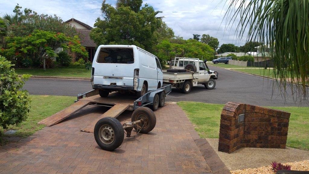
And Betsy heads off into the sunset. Goodbye my old friend.

-
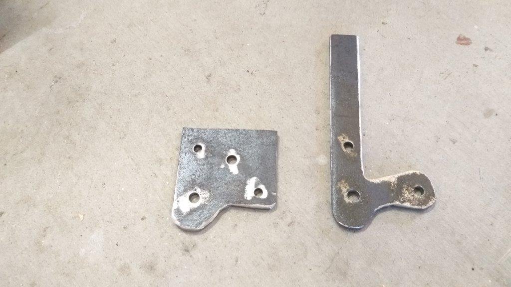
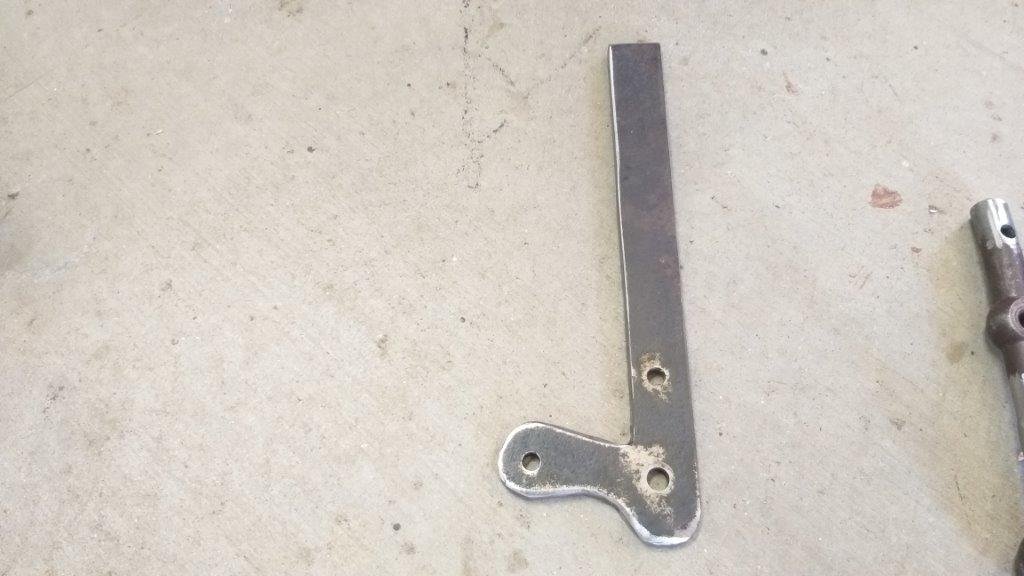
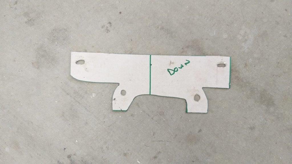
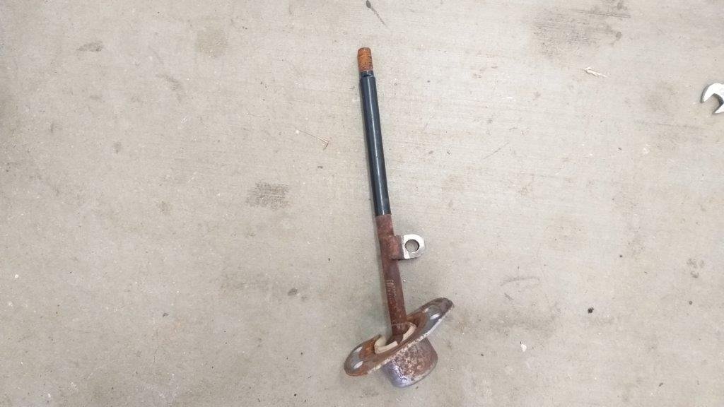
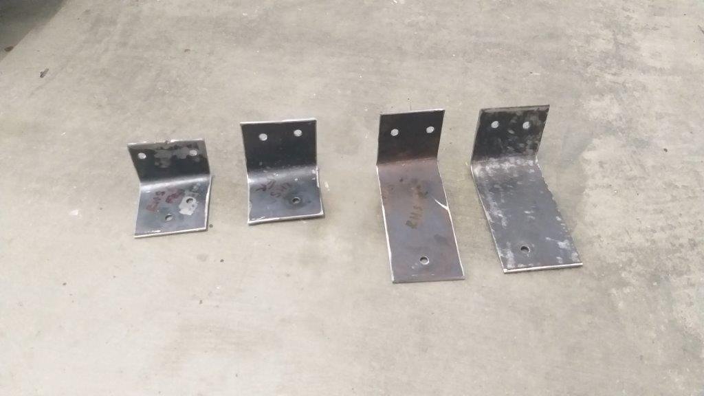
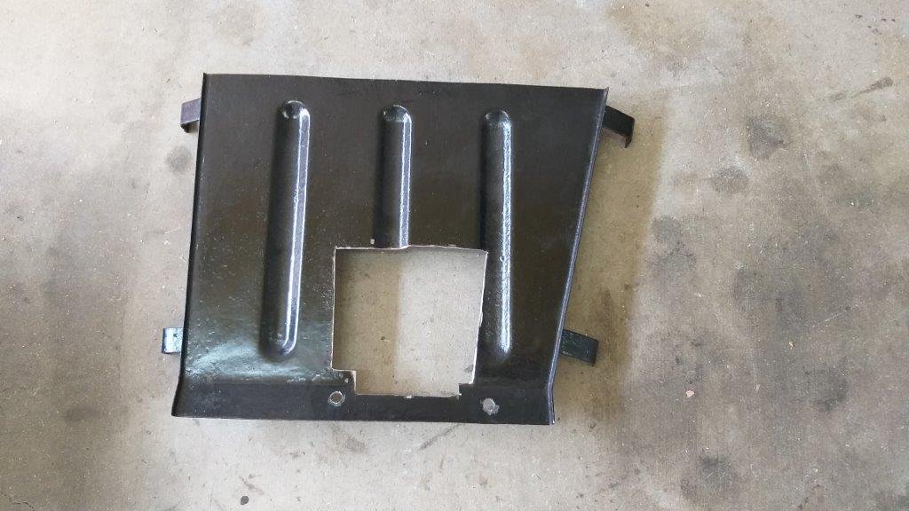
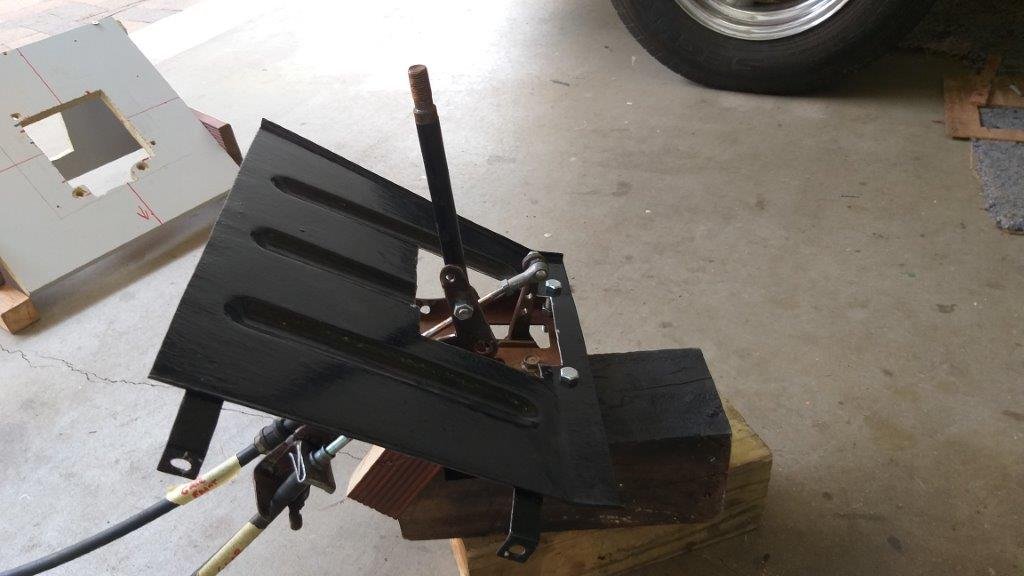
Had to make a MK2 version of my gear cable holder bracket to position the connecting rod closer to the pivot point as I was getting way to much sideways travel when selecting gates. New version next to old for comparison. The extra hole in the new bracket on the right is where the connecting rod attaches.
-
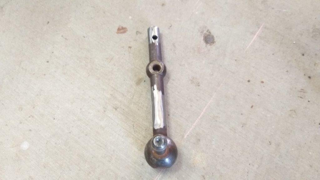
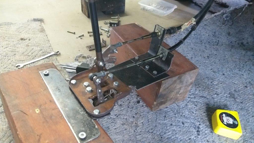
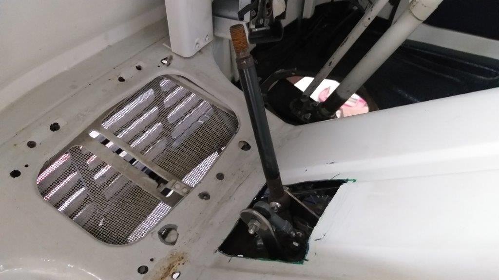
This morning I cracked into the final bit of fabrication on the main gear shift mechanism. First order of business was to create a new gear cable mount to replace the one that is currently only held on with one bolt. I'll be cutting off the round gear stick and replacing it with a flat piece of steel to which I can attach the shift rod for the remote shifter, so I thought I'd tackle that at the same time. I'll let some pics do the talking. Next order of business is the primary gear stick setup. Thanks for looking.
-
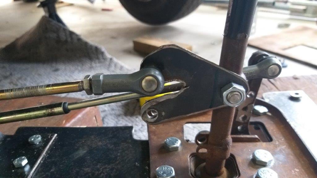
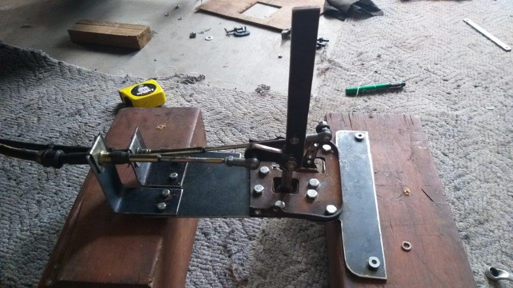
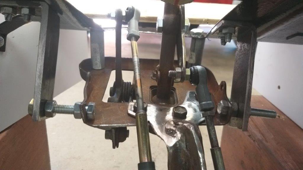
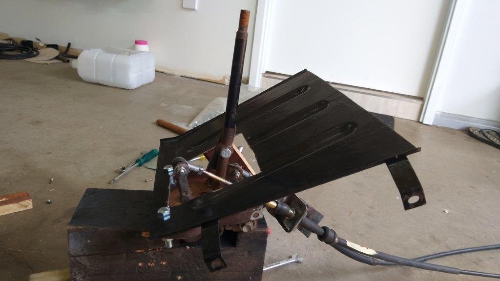
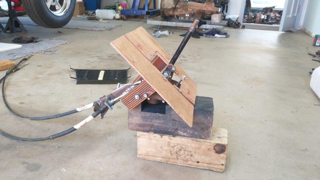
Okay, so in my eagerness to share my updates I missed out some crucial information that pertains to the last photo in my previous update. Allow me to elaborate: The new position of the gear shifter solves two issues that I had encountered with my previous version. The first issue is related to the original angle of the cable holders which I had to point downwards in order to clear the radiator. Now that I have moved the shifter out of the tunnel and further forward I can now run the cable holders a lot flatter as the cables now happily clear the radiator core. This has significantly reduced the added friction in the cables due to the unnatural angle that I was running the cables at. The second issue that I had was the length of the throw on the gear stick. This was due to me having to attach the cables to the mechanism very low to the pivot point of the stick in order to get the mechanism as high as possible in the tunnel. Now that I have heaps of head room in the new location I have been able to attach the cables a lot further up from the pivot point which has significantly reduced the gear stick throw. Photo of the new setup attached to my "test bench" , oh and I was also able to glue back the original gate shift lever that I had previously cut off. Next step is to fabricate a new ball joint holding bracket for the gear cable as I've had to change the angle on the existing bracket and its currently only held in position by one bolt. Thanks for reading.
- 740 replies
-
- 10
-

-
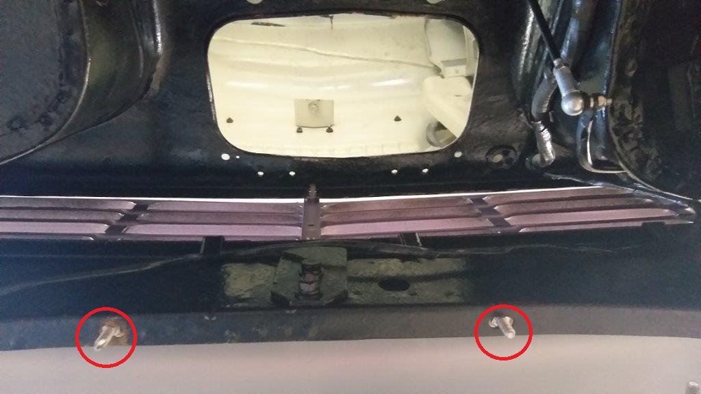
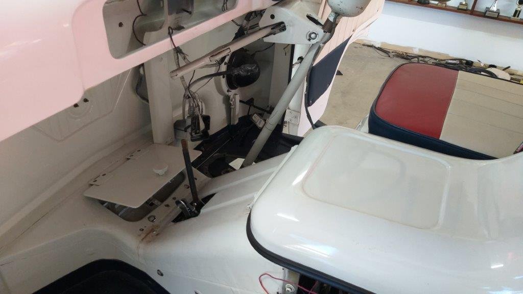
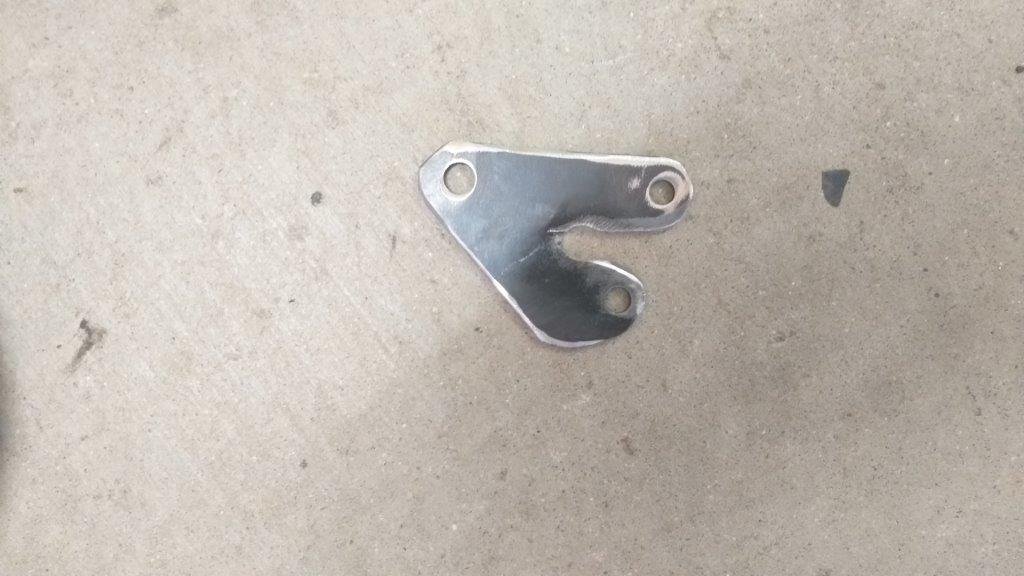
I then spent a bit of quality time under the front of the Thames puzzling out my next move. So what I'm thinking of now is to move the existing shifter out of the fresh air intake tunnel and as far forward as I can. I'll then mount the new gear stick further up inside the tunnel and run a connecting rod between the two gear sticks which should hopefully allow me to mimic movements of the new gear stick on the relocated existing gear shifter. Hey its worth a go I reckon. It's only going to cost me a bit of time and a few steel off-cuts. So first step was to relocate the shifter. I found two factory holes in the front valance that look like the perfect front mounting points for the shifter. Proceeded to do some CAD design and a little metal carving and I ended up with this:
-
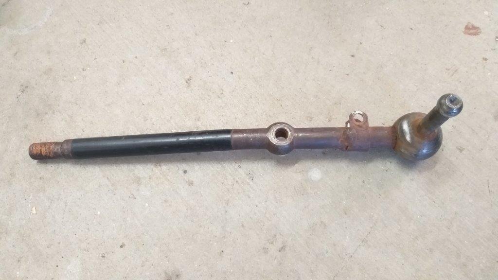
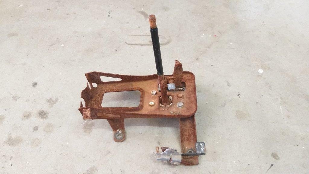
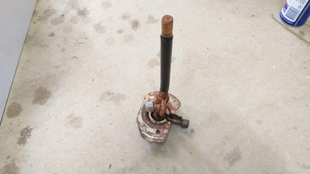
Well it's feeling a bit like Groundhog Day here at Rough & Ready Restos as I embark on yet another version of my floor mounted gearshift mechanism. Yep, I know I've absolutely flogged this subject to death and I've lost count of the number of previous failed attempts, but hey I'm too dumb to have given up by now, so here we go. The last time I wrote about this I was looking at creating a remote gearshift setup to circumvent a ridiculously long stick throw with something that resembled the shape of an earth worm. So I'd purchase a duplicate of my existing gear shifter that I had grandiose plans for. First step was to disassemble and then cut up my latest purchase leaving me with just enough to create the beginnings of a new plan.
-
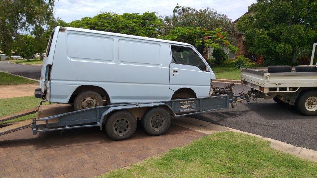
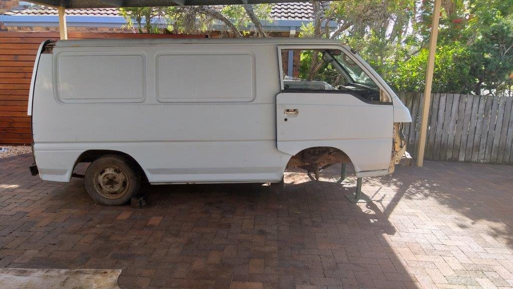
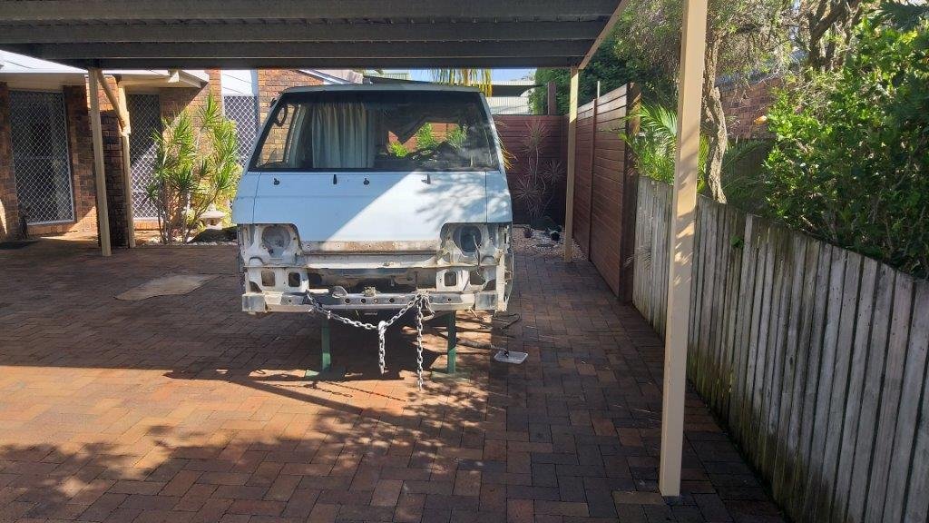
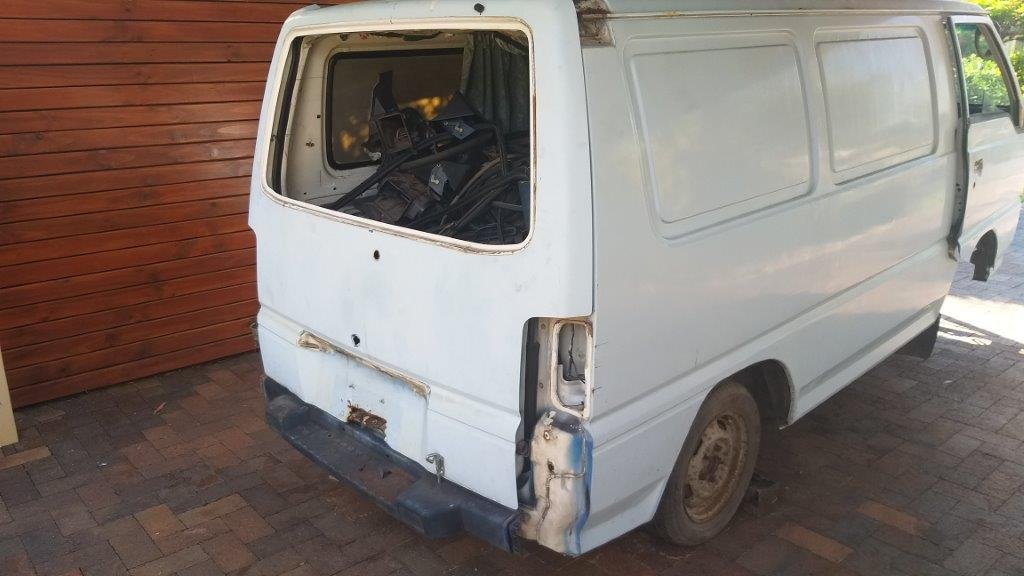
In between everything else I've been selling off a lot of unneeded parts from the donor vans. The week before last I had an oval track racer asking about the front stub axles, hubs, disks and calipers off the L300 Express. He races a Cortina TC and apparently they are a pretty sought after modification. Who would have guessed hey ? Anyhoo, I figured if I was going to sell them off I needed to get the rest of the van ready to depart as they are a pain in the arse to move around once they no longer roll. So Mrs Flash and I pushed it around to the main carport - which we now refer to as "The Surgery" - and I pulled the front out as well as the last small bits and pieces of value. Racer boy dropped around and parted with some cash, so everyone seems happy, including our neighbors who will be pleased to see the end of my mini scrap yard. The parts business has been a time consuming sideline, but on the up side I've managed to cover the purchase price and towing fees for all 4 donor vans as well as getting all of the parts that I needed for our Thames at zero dollars. All it's cost me is a bit of time and effort and a mangled finger which is thankfully now fully recovered A few photos of Betsy who is now patiently waiting for my mate Trevor to take her away to the crusher. I just hope we can move her with all of the crap that I have loaded into the back. My next update will hopefully feature some work on the Thames for a change. Thanks for looking.
- 740 replies
-
- 15
-
-
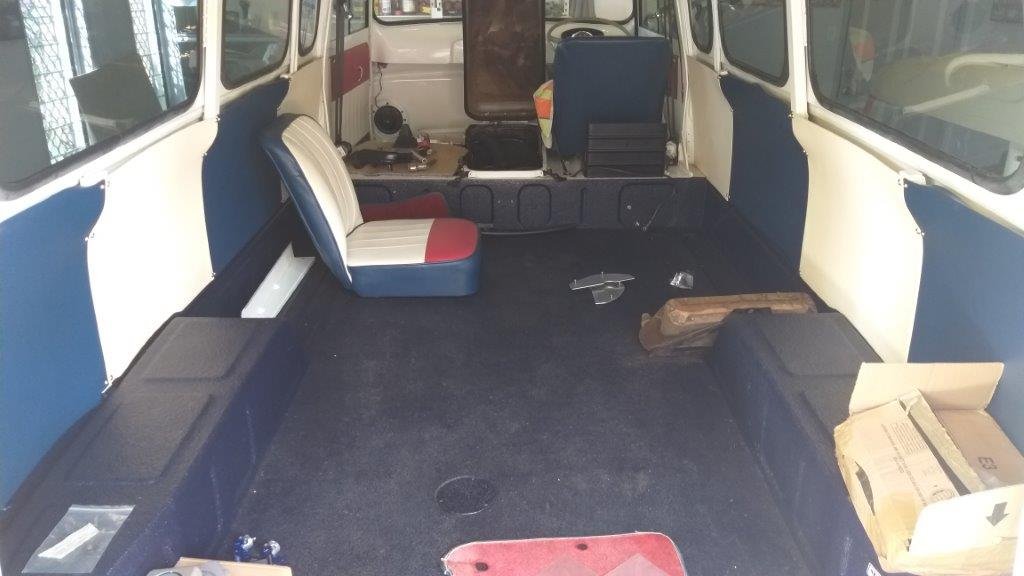
Now the back of the van looks decidedly spacious. And that's my excuse for not having worked on the Thames for the last few weeks.
- 740 replies
-
- 10
-
-
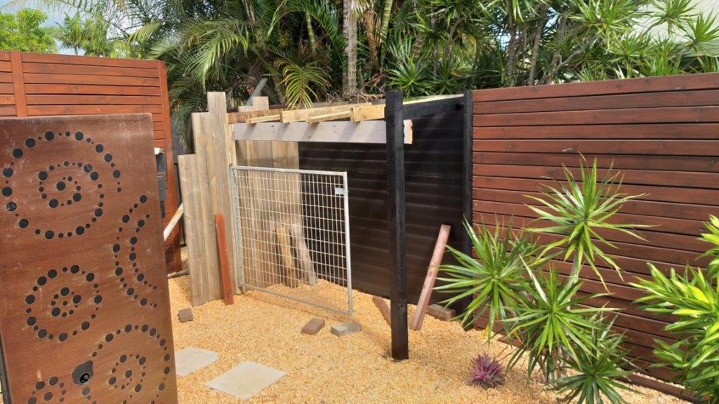
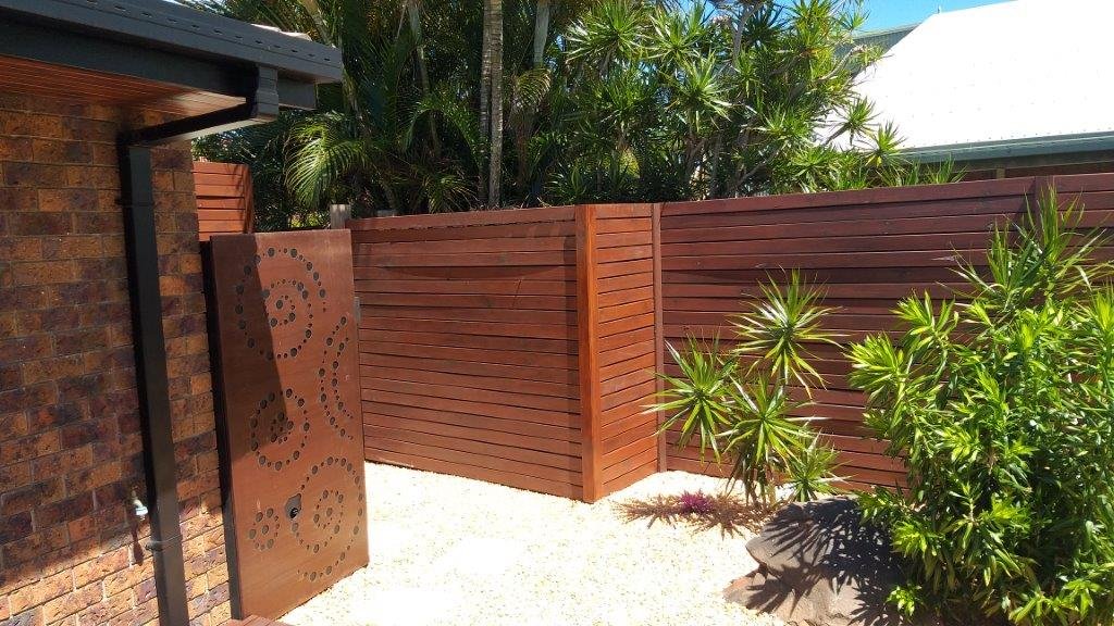
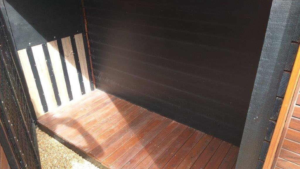
So the week before last I decided to do something about it. Looked through my pile of scrap and left over building materials and proceed to build a little storage shed which is right next to the pool. It's cunningly disguised to look like the fence that I built a few years back.
- 740 replies
-
- 12
-
-
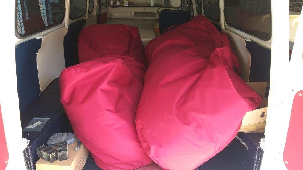
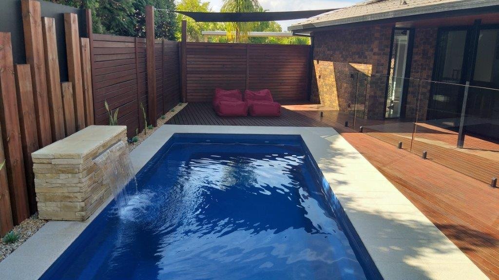
Over time the poor old Thames has turned into a bit of a storage shed the biggest items being our pool loungers which is a pain in the arse. Being red there is just no way that we can leave them out in the elements, so muggins here has to lug them out and back in every time we feel like lying by the pool.
- 740 replies
-
- 11
-

-
-
So now I'm thinking that a remote shifter would be the way to go. Something that will bring a shorter gear stick closer to hand and at the same time will clear both the top edge of the engine cover for rearward motion and the metal dashboard for forward motion. If I'm clever about setting up the pivot points I may be able to shorten the stick stroke at the same time. So with this in mind I headed out to my local wreckers this morning and procured this fine piece of equipment for the princely sum of $10. It's basically a duplicate of the shifter I'm currently using.
-
So what to do ..... I can't bring the gearshift any further up the tunnel as I need the cables under the floor to clear the radiator.
-
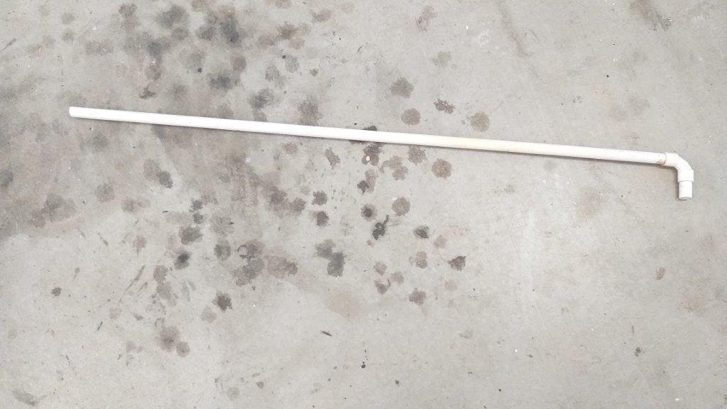
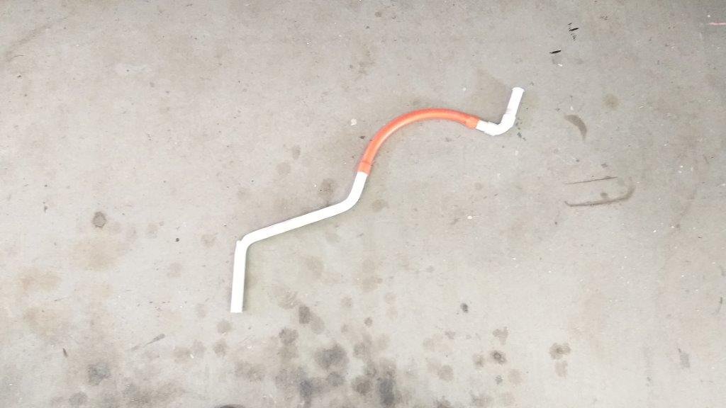
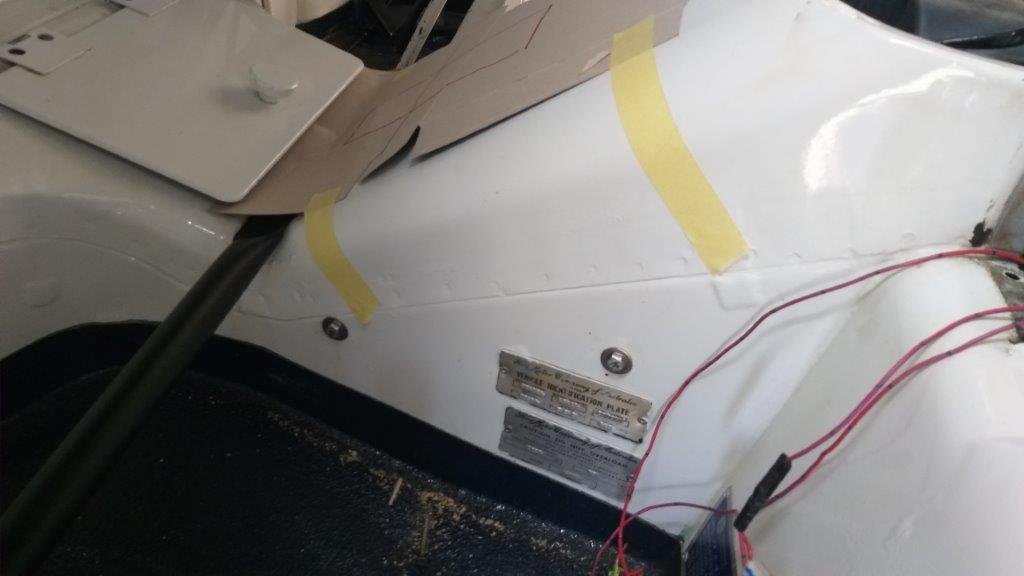
In my last update I glibly mentioned that one of my remaining tasks was to fine tune the angle and length of the new gear stick. How can something that rolls off the tongue so easily turn into another head scratching nightmare I hear you ask. Well let me explain: So the first order of business was to fit my driver’s seat as well as the engine box lid and fresh air flap so that I could ascertain the optimum height and position for the gear knob as well as confirming that the gearstick would clear all major obstacles when being put through the gears. I also needed to make sure that the gear stick was out of the path of the forward hinged engine lid for ongoing maintenance purposes. I thought I’d use an old bit of 20 mm PVC electrical conduit to mock up the shape and length of the gear stick before replicating it in steel. I’d envisaged needing a few subtle bends to get the desired outcome. How wrong I was ! Just look at the piece of spaghetti that I ended up with. Clearly that is not going to work.
-
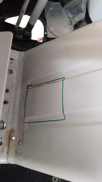
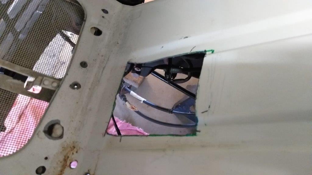
I spent the last few mornings fine tuning the floor shifter in an effort to reduce the size of the hole that I need to cut in the Thames floor to the absolute minimum. Ended up cutting off the factory "gate" shift lever from the Tarago mechanism and fabricating one that enabled me to further reduce the size of the hole. With that all done it was time to butcher the Thames, so I marked out the cuts with a sharpie and spanked it with my jigsaw. There's no turning back now. I've still got to do some final trimming and tidying up of my brackets and welds as well as sorting out the angle and length of the gear stick. I'll also need a rubber gaiter to cover up all of the mess. Thanks for looking.
- 740 replies
-
- 16
-
-

SR2’s 1947 Vauxhall “Rigamortice” Discussion thread.
Flash replied to sr2's topic in Project Discussion
Well said about the kindred spirits mate. I often think back on previous projects that I have done and how I would now do things differently being older - but not necessarily wiser. You are in the fortunate position to be making improvements on the same vehicle after so many years. Not many get that opportunity. -
SR2’s 1947 Vauxhall “Rigamortice” Discussion thread.
Flash replied to sr2's topic in Project Discussion
I'm chuffed to see that you are back into the Resurrection of Rigamortice Simon. I've missed your updates. Keep them coming ! -
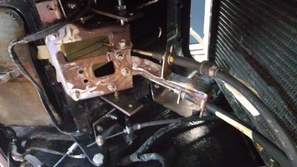
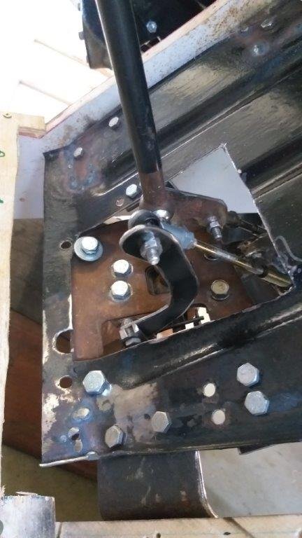
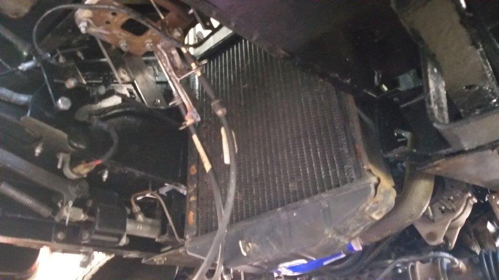
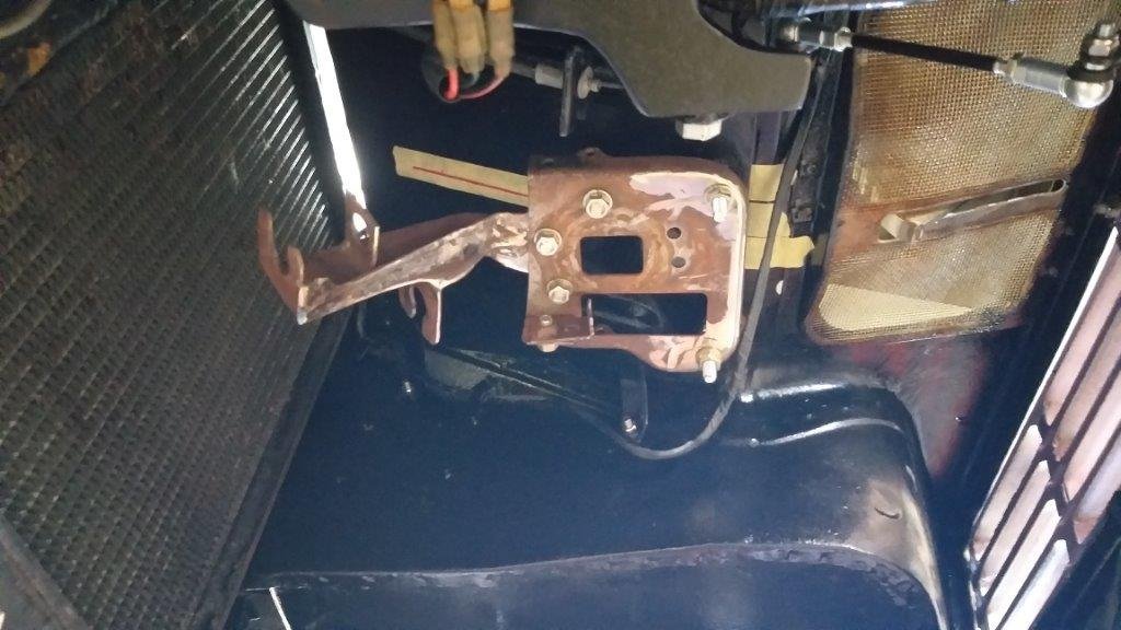
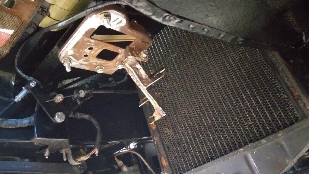
Quickly stripped down the gearshift mechanism and bolted the base plate in position to verify that my Morse cables are definitely going to clear the radiator. Yep, looks okay. For peace of mind I'll fabricate a bracket to hold the cables permanently away from the radiator core. No more excuses now Flash, so time to take a cement pill and poke that hole in the floor ! Before you run off to Specsavers I'd just like to apologise for the quality of the pics.
-
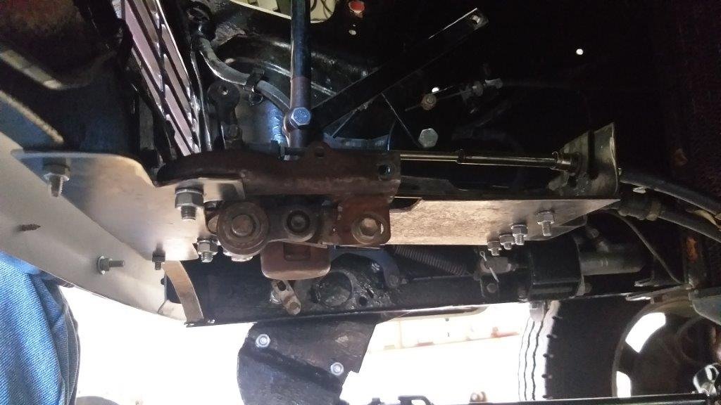
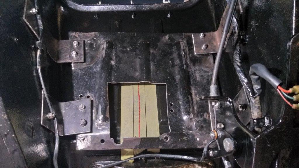
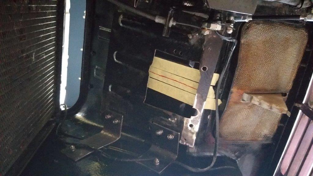
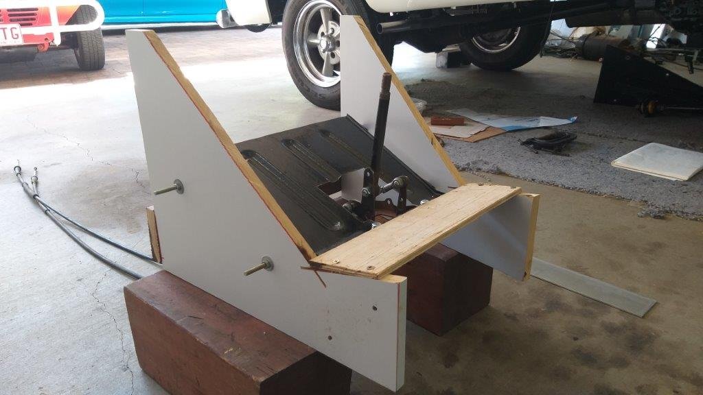
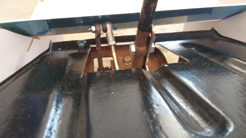
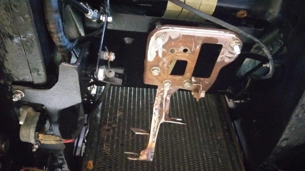
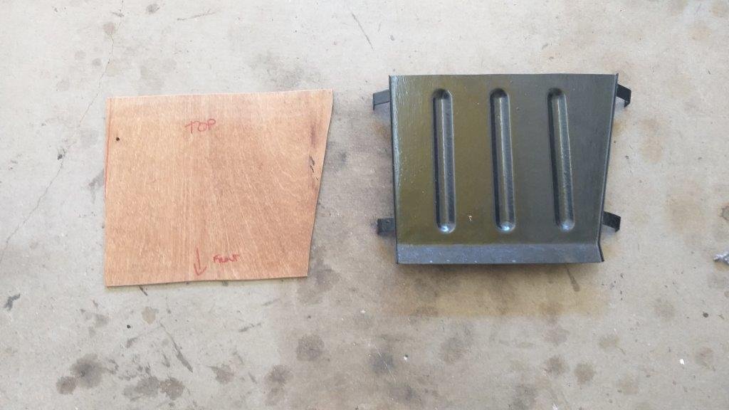
It's just before 9 am and already a hot and sticky day here at Rough & Ready Restos in sunny old Queensland. Just perfect weather for grovelling around under the Thames. Thought I'd start the day off by test fitting the intermediate tunnel plate with its newly fabricated mounting brackets. Up to now all work has been done using the wooden mock up tunnel, so I was pleasantly surprised when all the holes lined up and everything bolted in perfectly. I failed to mention in yesterday's update that whilst still in the mock up phase I had raised the plate by a good few inches taking it closer to the actual Thames floor. I did this to reduce the gear stick throw and thus in turn reduce the size of the hole that I need to poke in the Thames floor. I'm still using the factory original bolt holes for the intermediate plate so the L brackets needed to be made a lot longer to accommodate the plate shift. The below photos give a general idea of what is actually going on now that the mounting plate is fitted. Next step is for me to put on my big boy pants and poke a great big hole in the Thames floor.
-
According to the Captain's Log today is day 374 on the Thames. Time sure does fly when fun is being had. I'm hoping that some of you can relate to the update I'm about to share. Sometimes it's the simplest tasks that take the most time and I would never have guessed that it would take me three mornings in the shed to fabricate 4 little brackets for the tunnel plate that I am mounting the floor shift to. Let me explain: So as I've mentioned before the plate was originally designed as a wind deflector that channeled cold air from the front grill to cool the engine box lid. As a result the original 4 little mounting tabs tack welded to the plate by the good fellows at Dagenham would never be up to the task of handling ongoing force from repetitive gear changes, so I decided meatier mounts were required. I started off by cutting and bending some brackets out of 2 mm steel that I welded to the plate. All looked good when I test fitted it to my mock up tunnel, but when I came to mount the plate in the Thames tunnel there was an instant fail. Due to the funnel like shape of the tunnel, the only way that I was going to get the plate in position was by removing the radiator and sliding the plate forwards. Although this is achievable now, there is no way that a lazy sod like myself is going to remove the radiator every time I want to take out the gearshift for future maintenance, so I ended up cutting off my newly welded brackets and made up a "bolt in" set. Took forever to do as I could only tackle one bracket at a time. Undo the plate.... cut off one bracket .... bend up a new bracket ....... poke some holes in it ...... clamp it in place ..... poke some mounting holes in the plate .... test fit it into my mock up tunnel using the remaining 3 welded brackets and the new bolt on bracket ...... poke another hole to line up with the original Thames bolt hole in the tunnel wall ....... confirm everything lines up correctly. Repeat above process 3 more times. Mind numbing to say the least, but I'm happy to announce that the 4 brackets are done and dusted. Tomorrow I'll crawl under the Thames and bolt the whole lot together in its forever home. With a bit of luck all goes well. Thanks for reading and stay tuned for the next exciting episode.
-
I was planning to weld a little "ear" onto the gear stick to hold the "gear" cable, but then realised that I'm going to need to keep the "ear" removable if I'm wanting to be able to strip the mechanism down for maintenance purposes in the future. So I ended up carving a little "ear" that bolts up to two existing mounting points on the Tarago gear stick. Bolted it together once again for a test. Success ! With the mechanism now largely completed, I cut a piece of ply and attached it to the top of my mock up tunnel to represent the actual Thames floor. I've kept the opening oversize for now. Tomorrow I'll make a little filler panel based on the final gear stick movement and I can then determine the size of the rubber gaiter that I will need to cover things up. Thanks for looking.
-
Spent another fruitful few hours on my floor shift conversion again today. Managed to fabricate the last two mounting brackets, then bolted the mechanism into my mock up tunnel. I've still got a few spacers to fabricate but its fine as is for testing purposes. Chucked the other end of the morse cables onto the HiAce gearbox for a further check. Put the shifter through its paces and I'm very happy with how its turning out. It's becoming a busy little space inside the tunnel.
-
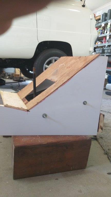
Spent a few hours this morning building another replica of the air tunnel / engine box front panel. Started off by making a cardboard template of the side profile which I then replicated in some old chipboard that I had lying around. Got the position of the intermediate plate's mounting bolts pretty spot on so I was able to bolt in the intermediate plate complete with attached shifter. As I suspected I'm going to need to lower the shifter base a bit more so that my "gate" lever will clear the tunnel top, so that's what I'll tackle next.
-
Took a courage pill, sat quietly in a corner until the effects kicked in, then traced my MK2 template onto the plate and quickly poked a hole in it with my baby grinder of angles. Bolted everything back together and gave it a quick dry run. Looking good, but the gate lever pokes well above everything, so I will likely need to lower the mechanism a bit more in order to clear the cabin floor. Next step is to bolt the intermediate plate up under my wooden tunnel mock up to fine tune the height clearance before I fabricate the rear mounting brackets for the mechanism base plate.
-
Spent this morning working on the MK2 version of my gear shift mock up and I'm much happier with the proposed position of the gear stick. I then disassembled the shifter one more time, drilled the first of the mounting holes in the intermediate tunnel panel and bolted the panel in for a quick test fit. The good news is that it clears my accelerator mechanism and the gear change cables look like they will clear the radiator. So now I need to take a courage pill and start cutting up my intermediate tunnel panel.
-
Thought I'd start the process of converting the plate, by creating a mock up in wood. This will allow me to have a few goes at getting the position of the mechanism exactly right before I start hacking up the real deal. So, this morning I put together a MK1 version. The angle of the base plate is pretty good and the cables now point downwards in order to clear the radiator core. The angle of the gear stick will need to change and also the gear stick has ended up further up the tunnel wall than I would like. All good learnings so tomorrow I'll crack into the MK2 version. Thanks for reading.