Flash
-
Posts
1615 -
Joined
-
Last visited
-
Days Won
2
Everything posted by Flash
-
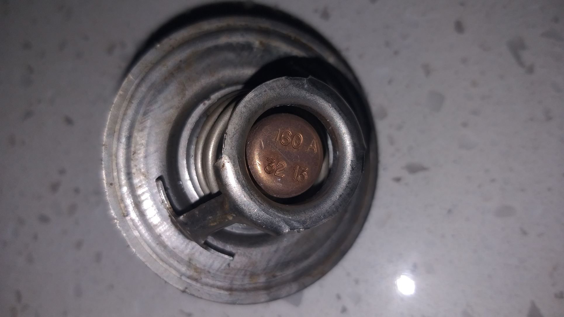
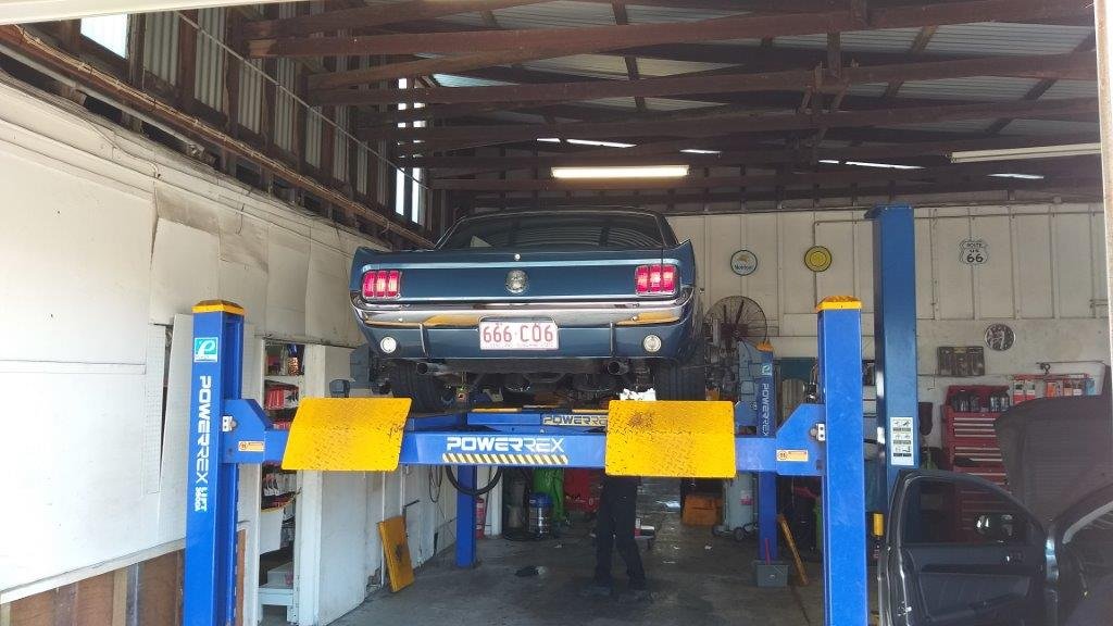
Cooling Issue - Chapter 4 I'm the first to admit that I've never really given much thought to thermostats and the role that they play in the cooling system, but over the past week I've been doing a bit of internet research on the subject and I've come to realise just how little I know. Now we all know that there is a lot of mis information out there on the web, but during my meandering I came across a guy called Walter who owns a Mustang GT350 and he has posted a number of interesting cooling related Youtube clips specifically covering the early Mustangs. I've got to say that what this guy says makes a lot of sense. I've always thought that the role of the thermostat is purely to get the engine up to optimum operating temperature as quickly as possible. But, Walter enlightened me to the fact that the thermostat's primary function is to regulate the flow of coolant between the engine and the radiator with the goal being to keep the coolant in the radiator as long as possible in order to cool it down. I'm embarrassed to say that whilst this may seem pretty obvious to most of you reading this, it was news to me. Another thing that Walter confirmed is that the little 289s like a bit of heat in them, so temps in the early 200 F range should not seem scary. The gents at Ford fitted the 289s with a 195 F thermostat from factory and Walter reckons they were bang on the money. Anything less and the coolant doesn't spend long enough in the radiator to drop the temp sufficiently. Walter further states that 80% of all cooling related issues experienced are attributable to either a faulty or incorrectly spec'ed thermostat and since this is the cheapest and easiest component to replace he recommends that this should be the first port of call. Now I'm not saying that what Walter is saying is gospel, but he makes a lot of sense, so I'm going to follow his advice. I mean, what have I really got to lose. So, with renewed vigour I popped the Mustang up on my ramps this morning and dropped the coolant. Pulled the thermostat that is currently in the engine and sure enough .... it's a 160 F jobbie. Looks to be pretty new too, so I'm guessing the PO has been in here already. Anyhoo, I've got a new 180 F thermostat on the shelf but I'm thinking I might just source a 195 and give it a whirl. Stay tuned for the next exciting episode as Flash shares more of his cooling related ignorance.

-
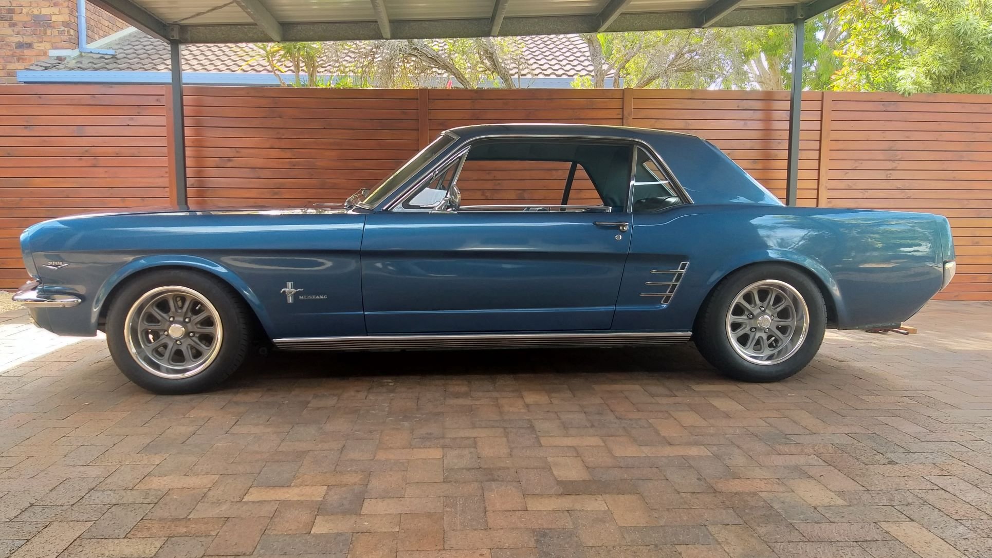
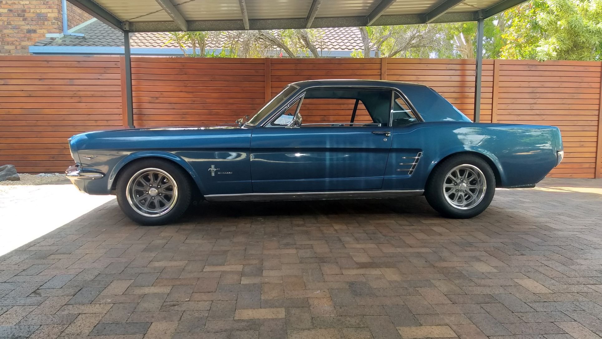
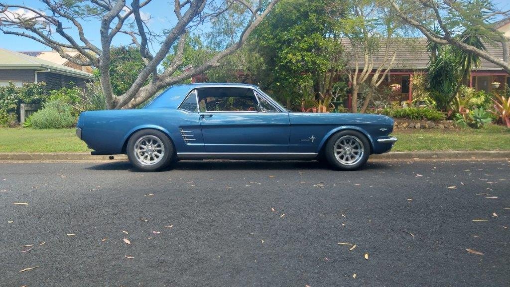
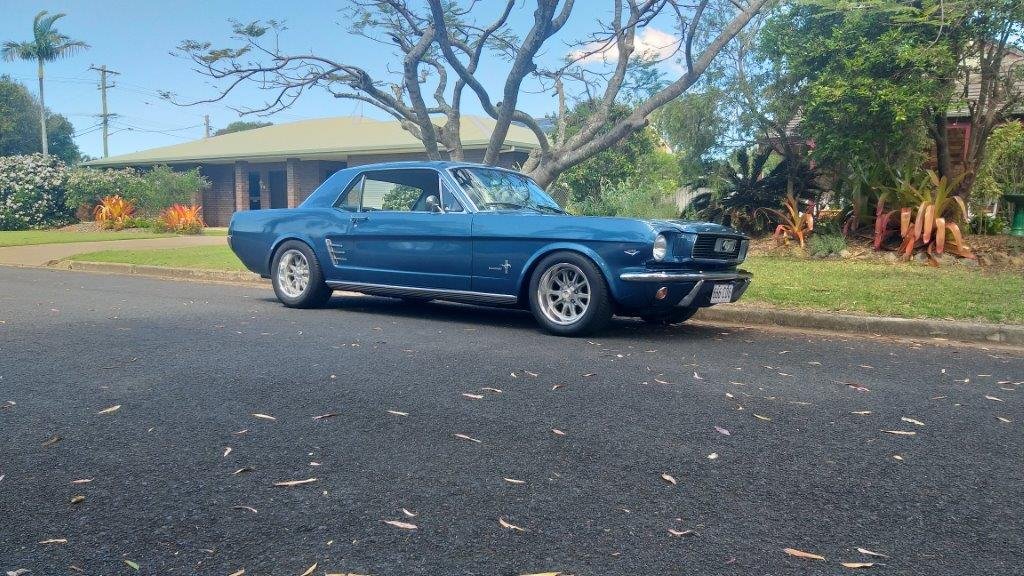
As part of my earlier fuel gauge sender repair, I filled the fuel tank right to the top. Last Sunday Mrs Flash and I and our wee dog headed out on a bit of a cruise, still with the full tank of fuel and with the extra weight I could feel that the rear suspension was pretty borderline. At one point we were on the rear bump stops whilst navigating one of the speed bumps along our beach front. In addition to this when viewing the car side on it looked slightly tail down. So, this morning I pulled out the 2 inch lowering blocks and replaced them with a set of 1 and 1/4 inch units that I had lying in the shed. Viewing the car side on it now has a slight rake to it, typical 70s hot rod look, which I kinda like. Took it along the beach front and we are off the bump stops now, so I'm much happier. Before and after side views :
- 194 replies
-
- 15
-

-
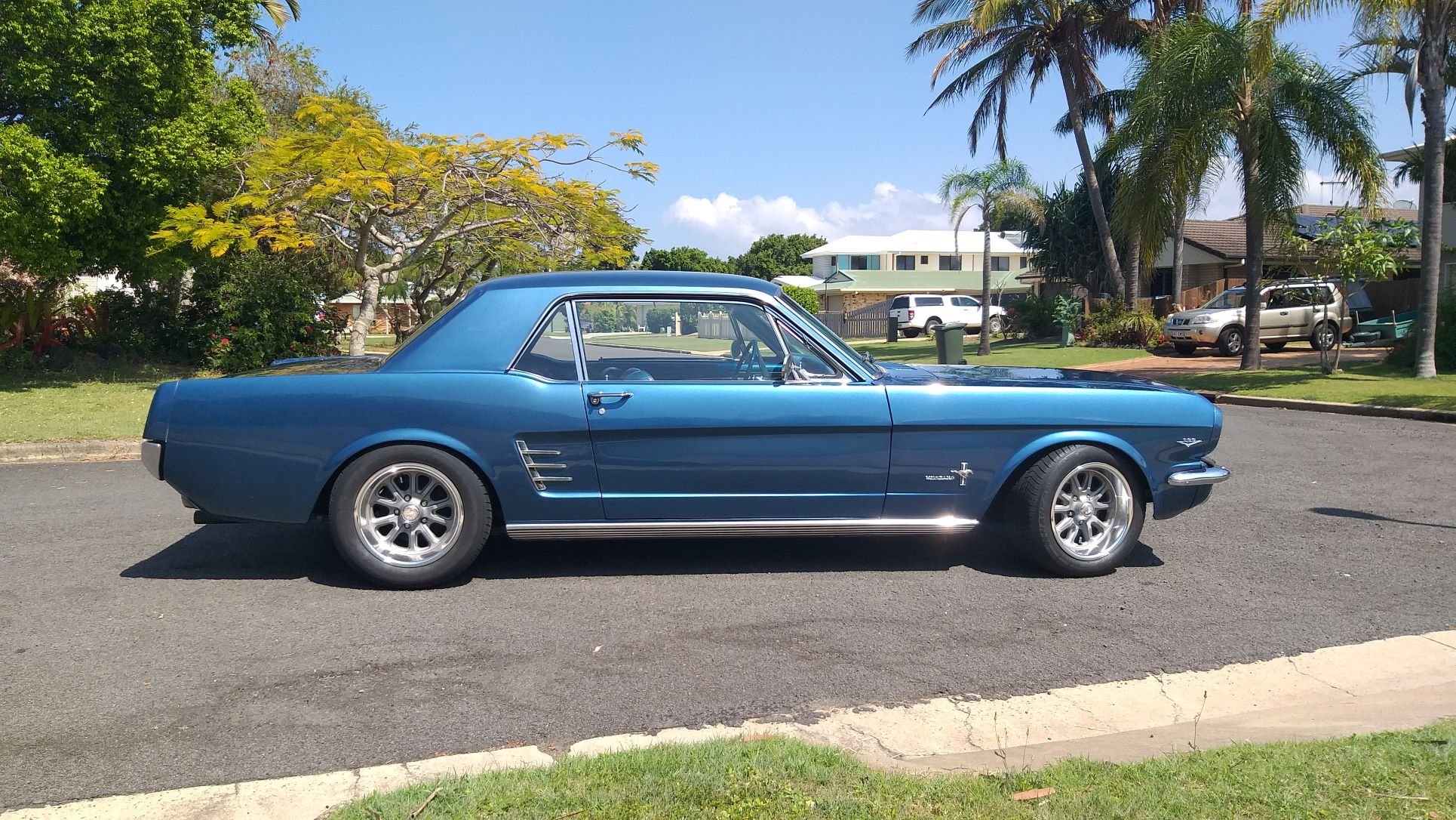
This morning I slapped a bit of Meguiars on the Muzzy. Gave my elbow a bit of a workout and then pulled it out into the sunshine to admire my handiwork. Doesn't look half bad, even if I say so myself.
- 194 replies
-
- 17
-
-
Cooling Issue - Chapter Three With my driveway idling test completed, I took the Muzzy out on the open road for some spirited driving. Worked things up to maximum temp and took a reading at the thermostat housing .... 200F ..... that's a little too high for my comfort. So, where to start? Well first up I'm going to flush the system. When I removed the heater core for refurbishing it was full of gunk and needed a good flushing, so I'm guessing the rest of the cooling system may be in a similar condition. Next up I'm going to replace the thermostat. I know there is one fitted as I could see it when I pulled the top radiator hose off, but I don't know what it is rated at. From factory the 66 was fitted with a 190F thermostat. The consensus seems to be that these are a tad high and most fit either a 160F or a 180F. I'm leaning towards a 180F as a starter for ten. I've got a new 180F in stock and will fit that after I have flushed the system. Both of these are cheap and easy to accomplish so worth a shot. Longer term I'm leaning towards a radiator upgrade, but I'll discuss this in a little more detail later. Thanks for reading.
- 194 replies
-
- 11
-
-
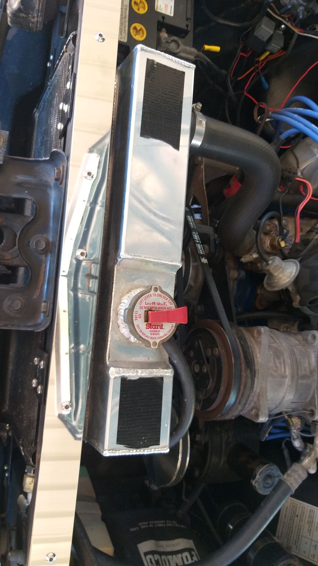
There are a few challenges when fitting a wider fox body radiator to a 66 Mustang. The first thing that needs to happen is the relocation of the battery to the boot. Next up you need to cut more out of the front radiator panel to increase the opening. The next challenge is to reroute your a/c lines as they now clash with the bigger radiator. I've also read that if you want to retain factory radiator hoses you can use the fox body ones, but you need to use the fox body a/c, alternator and power steering pump brackets as well as a water pump. The alternative is to seek out alternative radiator hoses that will fit around everything.
-
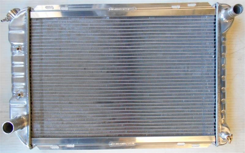
Yep, agreed. From what I have read the side tank layout was driven by the need to reduce bonnet height in modern cars that have much sleeker looking front profiles. The newer generation Fox body Mustangs run a similar setup but with the inlet and outlets on opposite tanks like this :
-
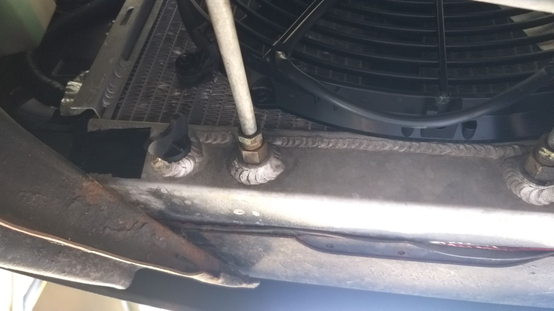
Cooling Issue – Chapter Two So armed with the infrared temp gun and following the advice of @sheepers, I stuck some bits of black tape on my shiny aluminium radiator and started taking some readings. The driveway test revealed that the thermo fan kicks in at around 170F. This measurement was taken directly off the thermo switch that sits in the thermostat housing. At that point the top rad hose measures 160F and the bottom rad hose 140F. The thermo fan cycles on and runs for about 4 minutes before turning off. Idling in the driveway for around 45 minutes the max temp measured was 185F on the top radiator tank. Monitoring the temps at various points on the radiator I’ve been able to establish that the difference in temperature across the top tank differs by about 15F. This supports articles that I have read that criticise Ford for having the radiator inlets and outlets on the same side as they reckon that the coolant ends up taking the path of least resistance and doesn’t utilise the full radiator core to maximum advantage. Some of the more expensive aluminium radiators are fitted with a baffle in the top tank to prevent this but clearly my cheapy radiator doesn’t have one. Apart from the fact that my radiator doesn't have a baffle fitted, I'm relatively comfortable with cooling performance at idle.
-
Cooling Issue – Chapter One The next big ticket item on the Mustang “to do” list is to improve the engine cooling. The 65 and 66 Mustangs are notorious for engine cooling issues. The main reason for this is a poorly designed piddly little radiator. Things get even worse when the car is sporting a/c as the condenser is mounted in front of the radiator which doesn’t exactly assist airflow. The boffins at Ford then increased the size of the radiator on the 67 and 68 cars, but cooling was still borderline, especially in the hotter USA states. Eventually Ford changed to an even bigger crossflow radiator in the 70s and this seems to have solved the issue Somewhere along the line my Muzzy has been upgraded to a 3 row aluminium radiator, but I suspect that the previous owner was still battling with temp related issues here in sunny old Queensland as the a/c condenser had been removed and the space filled with a helper thermo pusher fan. So far I’ve made a few changes that have improved things slightly, but I’m still not a happy bunny. First up I removed the cheapy pusher thermo fan as well as the original factory 5 blade mechanical fan and installed a 3000 CFM Spal puller fan on the back of the radiator. I was initially running a radiator shroud and whilst the car would happily idle all day on the driveway with the thermo cycling on and off, out on the open road under spirited driving conditions I noticed a drastic increase in temp. I ended up ditching the shroud and mounting the Spal directly to the radiator and open road temps decreased once again. However, now that I have refitted the a/c condenser in front of the radiator I’m again battling with open road driving temps and I figure I’d best knock this on the head before summer arrives and I get the a/c re-gassed. I’m worried that the warmer days and extra heat dissipating off the a/c condenser might just push the engine temp into the critical zone. So first up I needed to add some science to my investigation. I set my sights on finding something more useful than the factory temp gauge which helpfully has no temp markings. After pesting everyone on the tech forum page and getting some really good advice from the usual old school legends I got my hands on an infrared temp gun. Let the investigation begin:
-
Yep, it certainly could have ended in tears. That's always the worry with buying an old car. You never know what shortcuts one of the previous owners may have taken. Brazing the nut is a bloody good idea, so thanks for that @SOHC
-
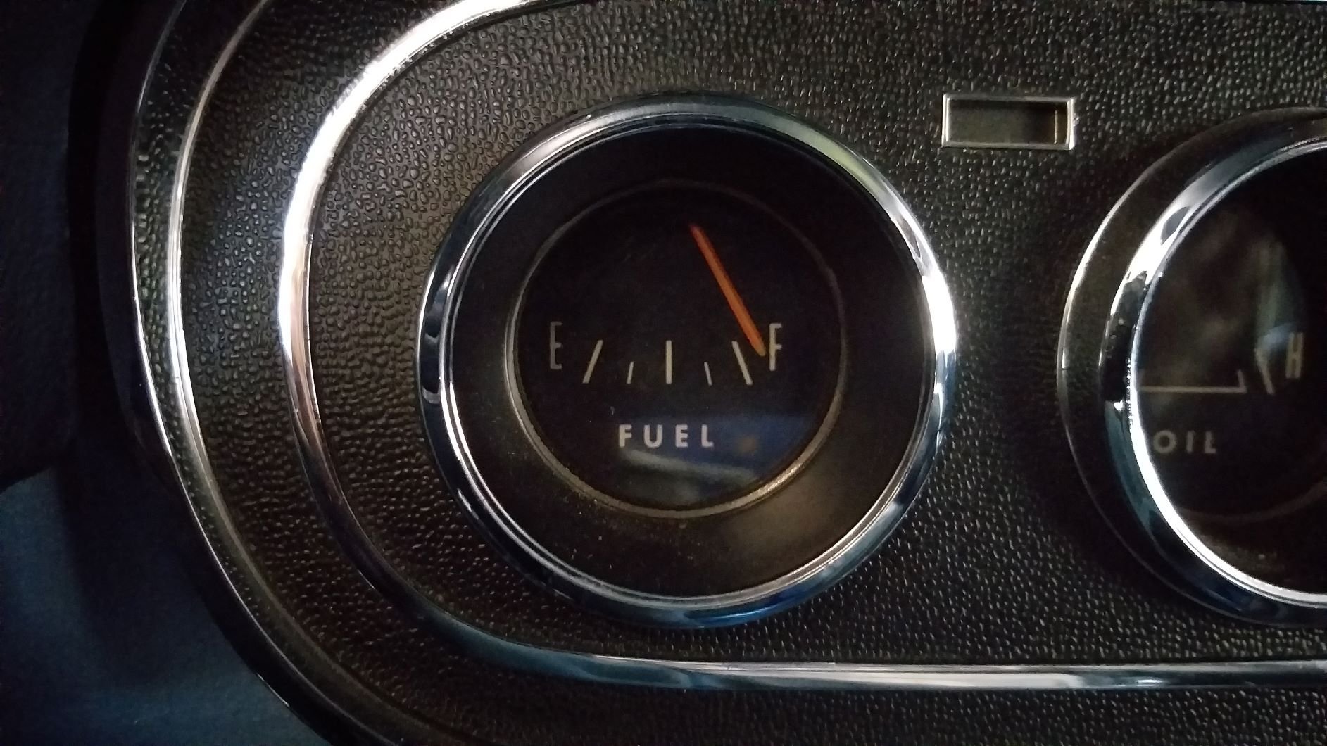
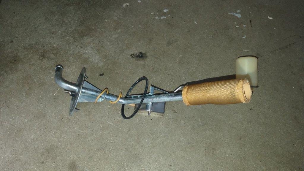
Fitted the new brass float to my fuel gauge sender unit and chucked it back in the tank with a brand new gasket. I've read that the aftermarket fuel senders are not that accurate on the old Muzzy's so thought I'd do a little exercise to see how bad it is. According to my Haynes manual the tank has a capacity of 60.5 litres so I started off by adding 15 litres to the dry tank. The good news is that there were no leaks. The bad news is that the gauge registered just above empty instead of the quarter tank that I was expecting. I then added another 15 litres which should have taken the tank to half, but the gauge only registered a quarter of a tank. With another 15 litres added to take the tank to three quarters full the gauge registered mid-point between half and three quarters. With the final 15 litres added to take the tank to full the gauge reads just past the full mark. So, yep ... reports that the fuel gauge is notoriously inaccurate are correct. On the plus side when the fuel level is low, I'd rather have a gauge showing less fuel than is actually left in the tank. Oh, and the added bonus is that the gauge actually works now.
- 194 replies
-
- 14
-
-
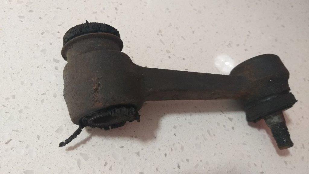
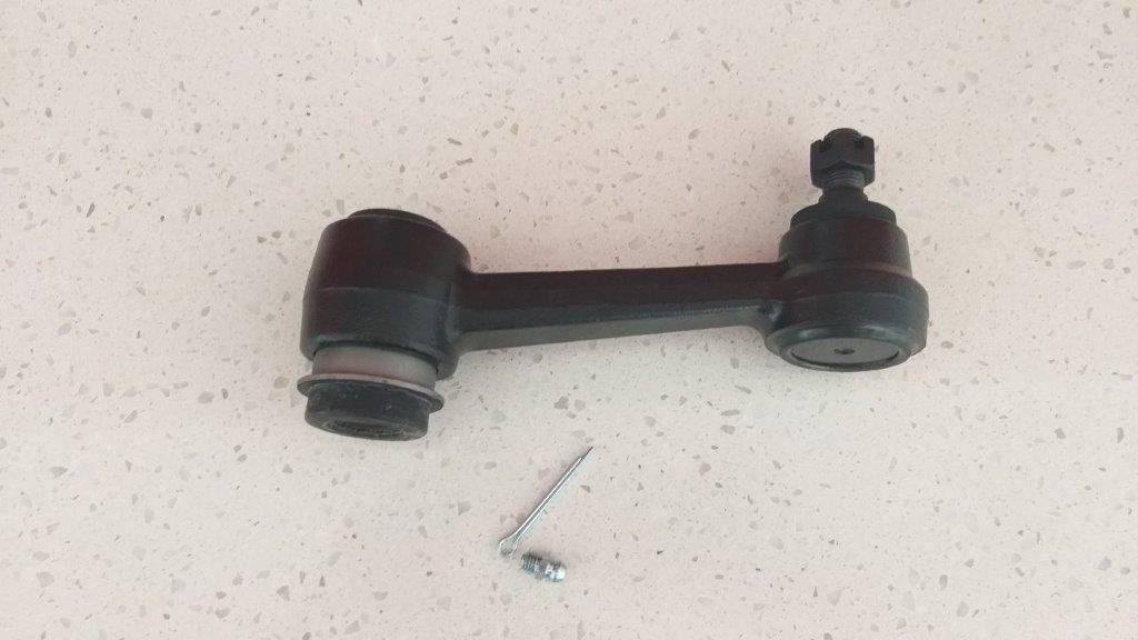
My new fuel tank sender float pitched up yesterday. I upgraded to a brass one as the plastic ones are notorious for developing leaks. While I was at it, I ordered a new idler arm as the bush in the existing one was looking a bit flogged.
-
Thanks for that @fuel
-
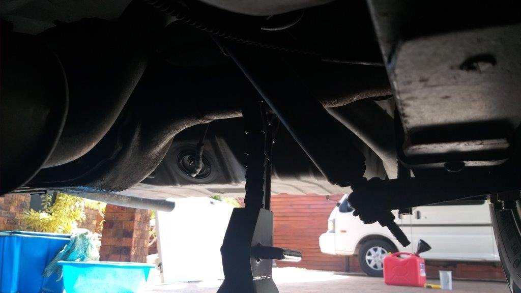
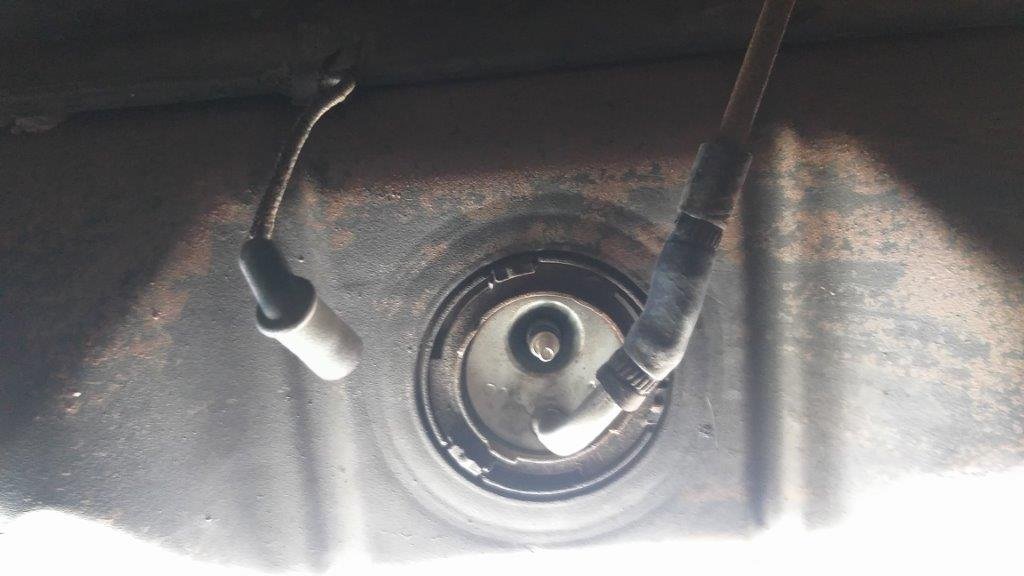
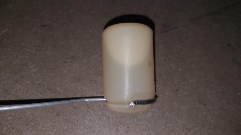
Woke up to the perfect morning for breathing in petrol fumes, so jacked up the Muzzy's arse to get the fuel sender unit out. The tank still had about 5 litres sloshing about in the bottom, but luckily I had a clean bucket close at hand and I managed to drain that off without incident. Popped the sender unit out and as you can see from the photos below its a fairly new unit. Took a close peek at the little plastic float and the cause of the non functioning gauge was instantly obvious :
- 194 replies
-
- 11
-
-

-
If I had given it the welly up my driveway that could potentially have ended in tears. Quickly pulled that sucker out with a pair of tweezers and chucked a locking nut on it so hopefully that won't ever happen again. On the plus side I managed to take a few shots of the Muzzy while it was sitting outside my neighbour's place waiting for a drink.
- 194 replies
-
- 23
-
-
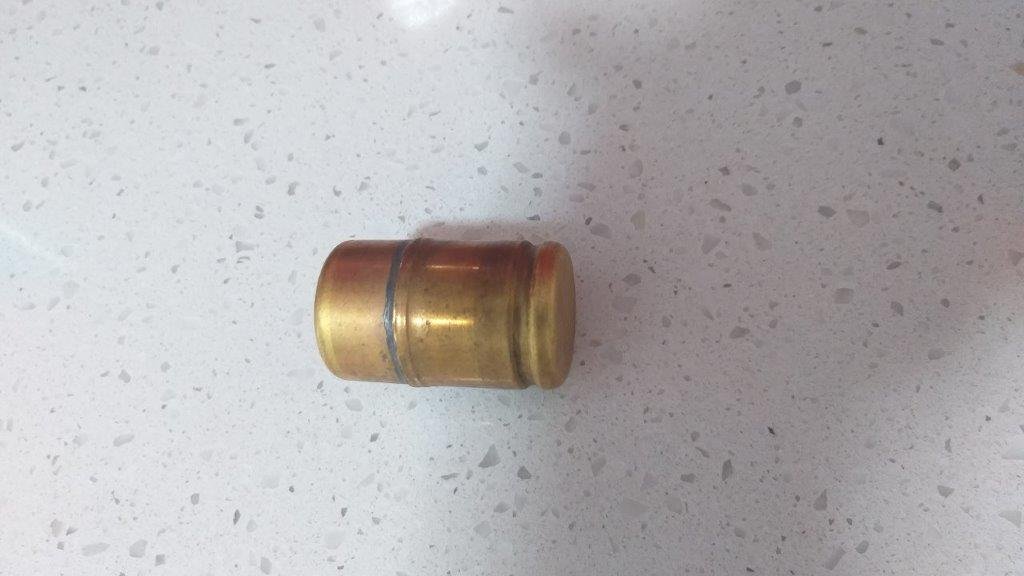
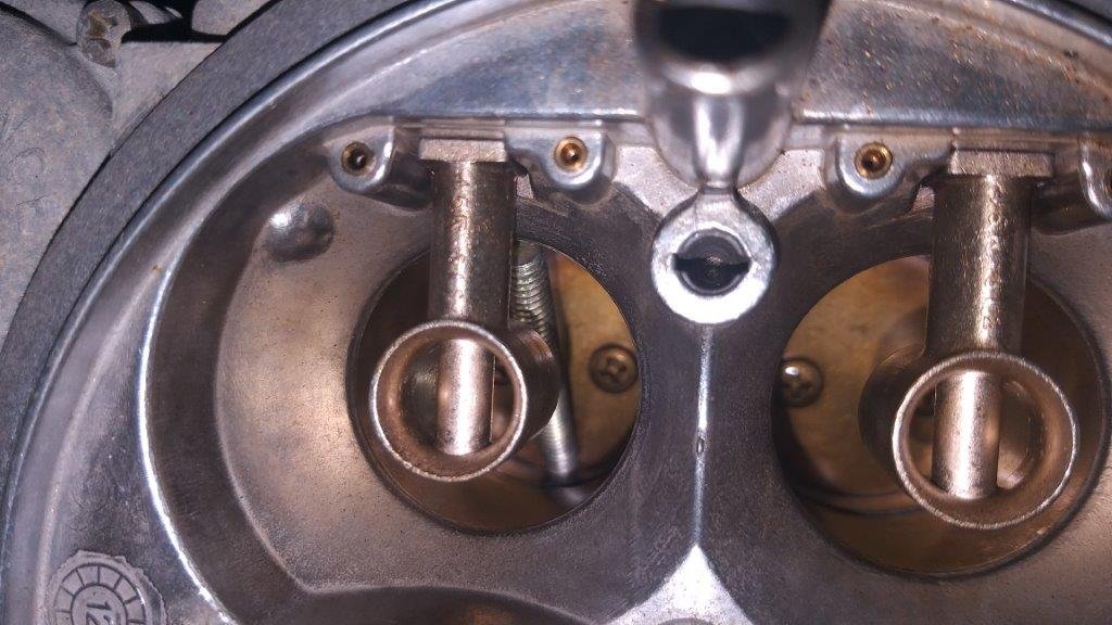
Jeez, I dodged a bullet today ! So, my fuel gauge hasn't worked from day one and earlier in the piece I traced the issue back to the tank sender unit. The good news is that the sender unit sits on the front side of the tank so at least I don't have to drop the whole tank to get the sender out. The bad news is that the sender unit sits on the front side of the tank so you have to drain the tank if you don't want to enjoy a 98 octane shower. As a result I've been putting the job off for a while, but now that the Mustang is almost about to begin duty as my daily driver it's time to address the issue. So this week I purposefully let my fuel level run low and then today I spent a good part of the morning cruising around the neigbourhood trying to run the tank dry. Yep, I know endless cruising around in a rumbling V8 is a thankless task, but someone has to do it. After a bit I started to get a hesitation on turns so figured I was close to sucking fumes. Headed home and managed to finally run out of gas two houses from our place. Bugger pushing the car home so I walked home and got a litre of fuel that I had put aside in an old milk bottle. Tipped the litre into the tank and thought I'd prime the carby with a few drops to make the starting easier. Removed the air filter for the first time ever by unscrewing the big center wingnut and carried it home together with the empty milk bottle, then back to the car which fired up easy enough and I idled her home. Back in the shed I figured I'd refit the air filter, but when I came to fit it the threaded rod that the wingnut goes onto was missing. My first thought was that it had dropped on the road while I was walking home, so I walked back down the road keeping a beady eye out for the threaded rod, Nyet, no sign of it. Retraced my steps home and checked out the shed floor where I had placed the filter. Still no luck. Checked the valley between the inlet manifold and the rocker covers. Nope .. not there. Got my torch out and took a gander down the carby venturies and guess what :
- 194 replies
-
- 18
-

-
-
Fellas, I really appreciate all of the advice and tips. Thanks very much.
-
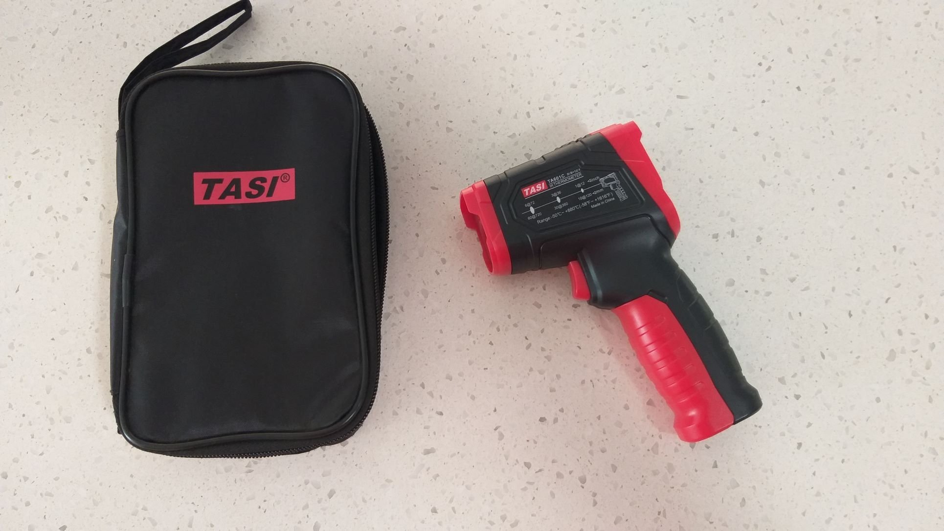
Hiya All. I'm about to start investigating a temperature related issue on one of my projects and I'm thinking a good place to start would be getting myself one of those infrared temperature guns so that I can check out what is actually going on at each point in the cooling system. Prices seem to vary on the units and I don't really want to spend more than I need to as it's not something I'm going to get a lot of use out of. But, I also don't want to buy something that isn't accurate enough as I could end up chasing my tail. I'd appreciate any suggestions on what unit to buy and also any tips or tricks on how to use the gun as I'm a newbie to all of this. Ta in advance
-
I've spent the last few weeks mucking around with the Mustang brakes. Patiently waited for the arrival of a few more brake related bits and bobs. Then needed two short hardlines made up as the outlets on the new master cylinder were different to my old original. Got those all sorted and installed, bled the brakes and finally dropped it back onto it's wheels yesterday. Luckily my local alignment shop had a last minute cancellation, so I was able to get it on the hoist first thing this morning. The upper arms need a few more shims added to get the camber spot on so I'll add those tomorrow and will take it back for a re-check. Photo, or it didn't happen :
- 194 replies
-
- 12
-
-
Hey @anglia4yes, my bad. I slapped the coupler on upside down for my photo. Thanks for setting me straight. I did some more research last night on this adjustable pushrod setup. It is a Scott Drake part - much like many of the aftermarket Mustang parts are- and in reading through their description of the part they state that it is to be fitted to cars with manual disc brakes only. Quoting from their product specification : "Does not work with power disc brakes" At US$ 50.00 it isn't cheap so whoever fitted it wasted their money.
-
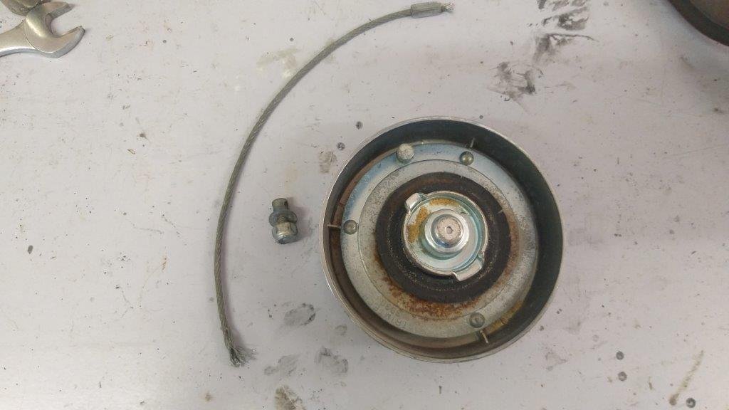
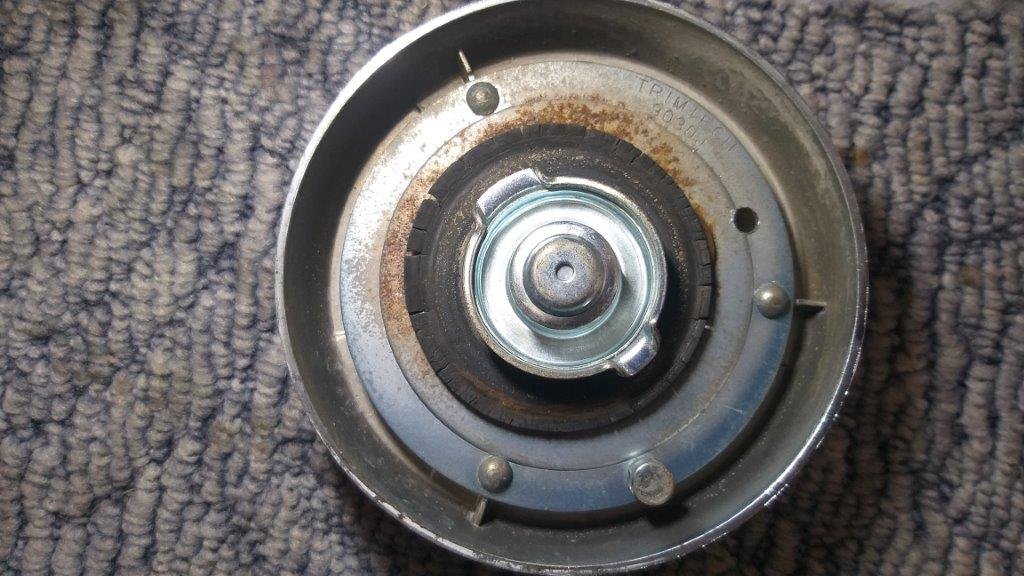
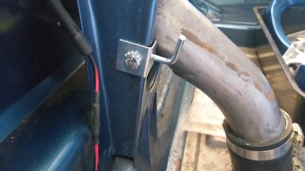
Comes with a set of instructions that even a fool like me can follow. First step is to unbolt the original retaining wire that tethers the cap to the fuel tank neck. Unfortunately you have to then sacrific the wire loop, but it's worth the effort. Then with the fuel cap in place you mark a pilot hole position at the back of the cap through the original hole that the wire loop retaining bolt passed through. Next you carefully drill a hole through the inner face of the cap taking care not to go through the outer brightwork. Then it's just a case of mounting the little spring loaded latch pin inside the boot. The spring loaded pin engages the hole in the cap when the cap is closed and the only way that you can open the fuel cap is by unlocking the car boot and disengaging the spring loaded pin while you screw off the cap. Bonus is that now that the cap is no longer tethered to the car, you can place it safely elsewhere while you fill up. Bloody clever.
- 194 replies
-
- 10
-
-
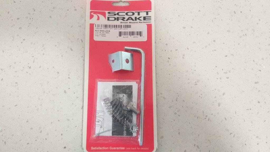
Now it just so happens that Scott Drake market an ingenious little locking kit that they sell for around $15. Probably costs about 15 cents to make, but the idea behind it is priceless, so I had to have one. Kit looks like so:
-
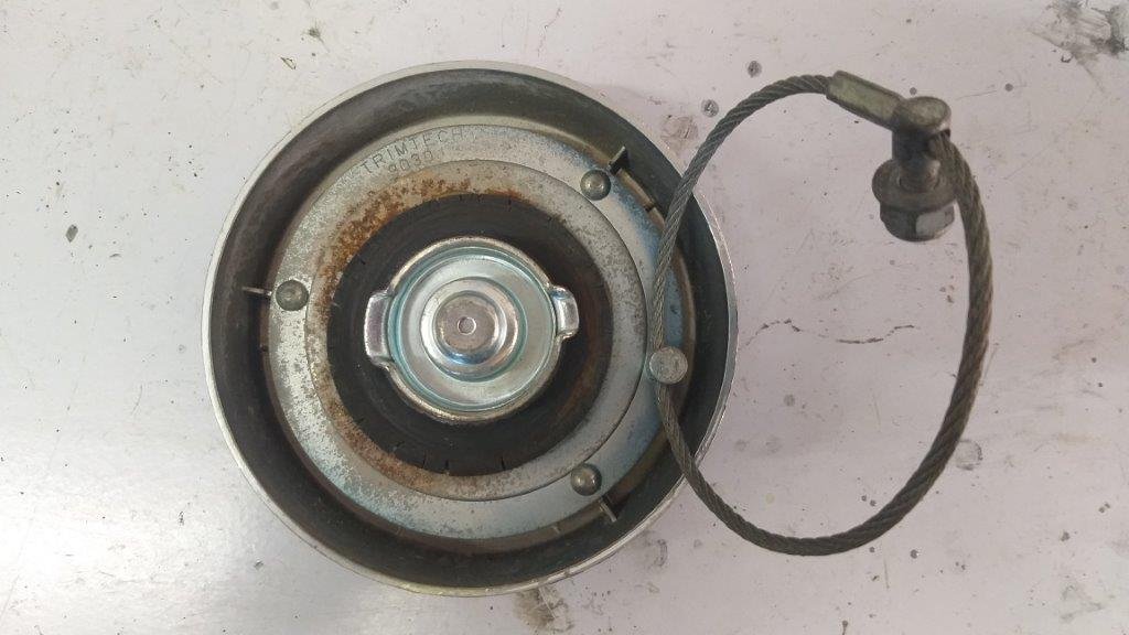
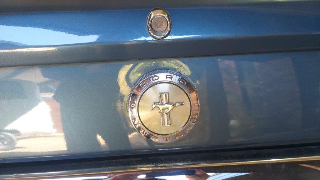
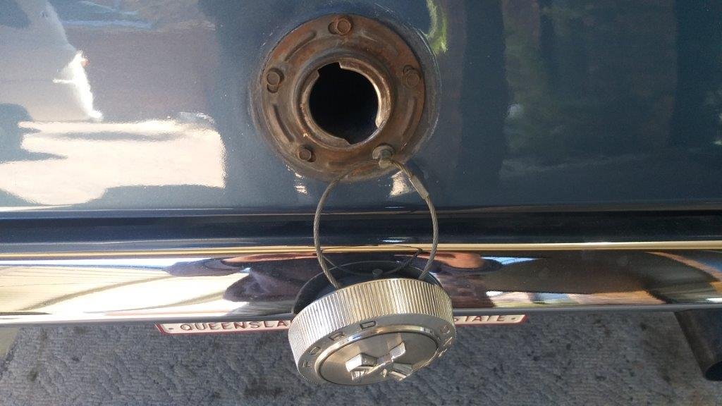
Thought I'd tackle a quick and easy job for a change. The fuel cap on the 66 Mustang is an absolute work of art. Although it looks bloody good its functionality leaves much to be desired. Firstly it doesn't lock which I'm guessing wasn't an issue back in 1966 but because I'm planning to use the Muzzy as a daily driver, I'm picking I'd be a sitting duck for fuel theft or even worse someone chucking a handfull of sand into the tank just for shits and giggles. Secondly when you do unscrew the cap it has a factory fitted retaining wire so it dangles down onto the back bumper. Just the thing to scratch the chrome or paintwork.
-
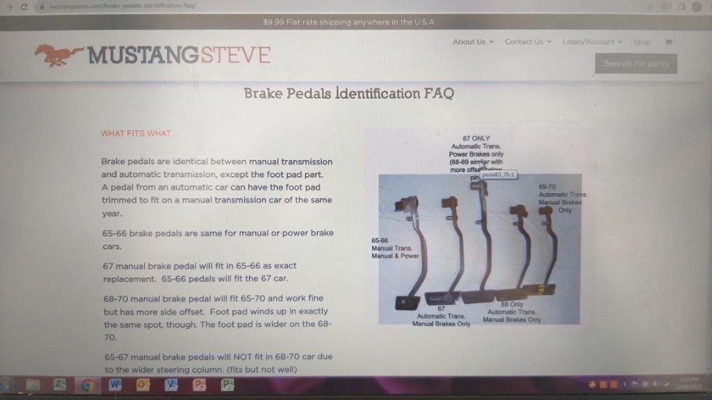
Thanks for the additional info @cletus I was anticipating exactly what you describe in terms of a factory pedal modification and from what I have read it seems like Ford built this into the Mustang brake pedals from 1967 onwards. All of the info that I have managed to track down thus far suggests that for the 65 and 66 Mustangs the brake pedal was exactly the same for both manual brake and power assisted models. I find this really hard to believe. I'm going to make contact with Rob from Sydney Mustang tomorrow morning to see what he says as he has restored and modified hundreds of earlier Mustangs over the years. Excuse the crappy quality screen grab below.
-
Okay, so if I use the straight pivot connector instead of the pivot lowering kit everything works smoothly. That is a plus, but I'm still left with the problem of the pedal ratio which would be back to the non power assisted ratio. Uncle Google tells me that for manual brakes the pedal ratio should be somewhere between 5:1 and 7:1 and that for powered the ratio should be somewhere between 4:1 and 5:1. So I thought I'd start off by measuring my existing ratios. Sure enough with the standard pivot connector I get a ratio of 6:1 and with the pivot conversion I get a ratio of 4:1. Okay, so if I'm going to use the standard pivot I solve my alignment issue but I end up back at a manual pedal ratio. Uncle Google tells me that this will result in twitchy brakes. Yikes that doesn't sound good Did some more searching on some of the Mustang forums and there are quite a few posts that say that for any Mustang prior to 67 the pedal ratio for manual versus power brakes was the same from factory. Now much as I would like to believe this I also know that everyhting you read on the net is not always true, so I'd really like to hear the opinions of those who have more brake knowledge than I do. Calling @sr2 and others ....... please help a brother out mate. Oh a picture of the brake bias adjuster that was hidden under the booster for anyone who is interested.
-
Now being an absolute ignoramus when it comes to brakes I ended up asking my good friend Uncle Google what was going on and it turns out that this little conversion kit is used to lower the pivot point on a non power assisted brake pedal to modify the pedal ratio for a power assisted setup. Okay ..... but how the hell does that work if the actuator rod fixed inside the booster remains at the same fixed height. Surely this will cause a mis alignment between the pivot point and the actuator rod. Got some mixed answers to this from Google. Some say that you need to raise the pivot point for the pedal at the same time. Looked at the pedal bracketry and yikes, modifying the pedal pivot point would require major surgery as well as having to remove the whole setup from the car to do the mod. So I'm definitely not going down that road. Is the booster perhaps mounted too high on the firewall ? Checked this out but the holes in the mounting brackets for the non factory booster are all predrilled to suit the original mounting points in the firewall so that would need modification as well as the hole for the booster neck in the firewall would need to be elongated. Again I'm definitely not going down that road. But all of this extra info got me thinking some more and I decided to try something different. The new brake kit was supplied with a different looking pivot connector, so I pulled off the conversion hardware and fitted the straight connector and then bolted the pedal back in the car. Next I bolted the new booster to the firewall. Grovelled under the dash again and guess what ... the booster actuator rod and the new pivot connector line up perfectly. Screwed the two together and gave the pedal a try. Nice and smooth. The two setups pictured below for camparison: