
_Matt
-
Posts
453 -
Joined
-
Last visited
-
Days Won
5
Posts posted by _Matt
-
-
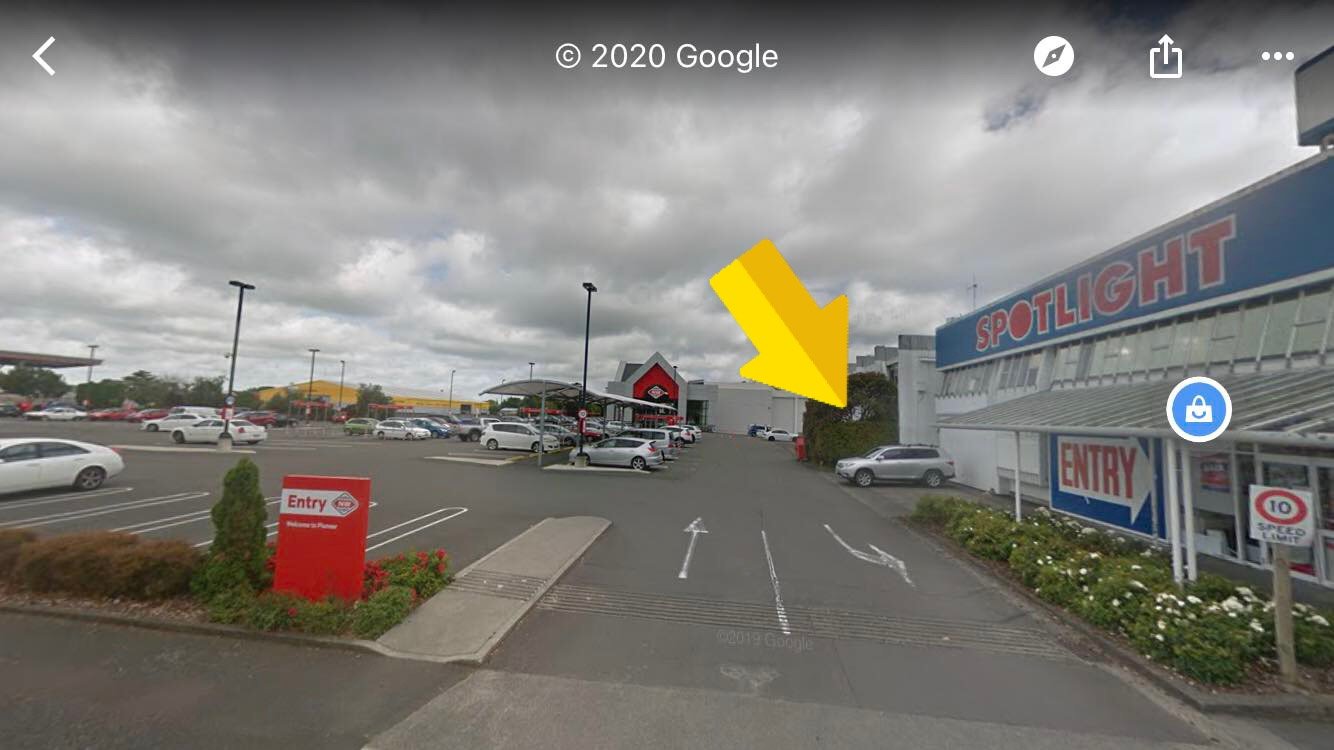
Hey guys, sorry missed a few months! Next meet we’re gonna try a meet at Shake Out, a burger joint, in the Pioneer New World car park just behind Spotlight on Main Street. It will be on the Tuesday the 20th of this month at 7:00pm.
See you there!
-
 3
3
-
-
- Popular Post
- Popular Post
Been slack at taking photos, although there's more photos than I thought there'd be.
Got the driveshaft hoops done. Rear one was pretty tight to fit in the tunnel. Front one didn't have much room above the driveshaft and shifter, but it all ended up pretty good.
Once the driveshaft and diff pinion angle was sorted I could finally fill in the new tunnel at the back.
I wanted to tuck the radiator under the radiator support panel, but there is usually another support that goes vertical down from the centre. So pulled that out and made up a new one out of tube, for a bit more room.
New thick core sort of tucks under nicely.
Built some stainless steel headers. Didn't take very long to make! The no.1 runner is a little longer than the rest so they aren't quite equal length but I'm not too worried anyway. I have now welded tension springs on to the collector and cleaned up the flange welds.
Made a little bracket for the oil level tube.
Made a reservoir for the brake and clutch fluid. Think I'll powder coat it black or something.
Made a Aluminium fuel tank. Slightly larger than the factory one and a bit more centered. The original strap mounts didn't really line up or exist anymore so had to weld some tube across the chassis rails.
As you can tell I also stripped all the old underseal off, took way too long!Stripped and cleaned the heater and then got all the steel bits zinc plated. Added some new foam on the sealing faces too.
Pulled apart the engine because I didn't really know what else to do/was waiting on some other bits to arrive haha. Everything looked alright in there. Have ordered everything to rebuild it apart from bearings, as I need to get them measured up. Borrowed a Ultrasonic cleaner and chucked most parts in there. They come out sooo good!
-
39
-
 4
4
-
- Popular Post
- Popular Post
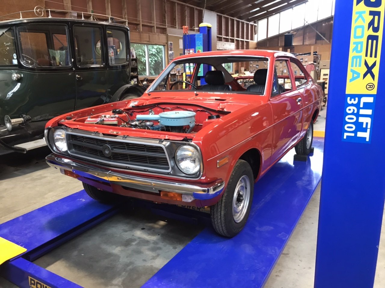
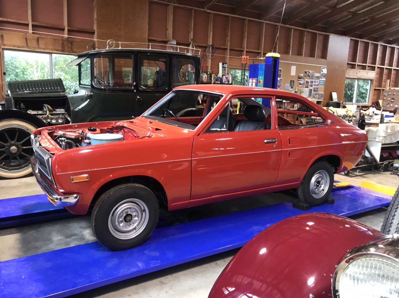
Datsun B110 being restored. Same owner bought it brand new
-
27
-
1
-
$807 inc shipping for the whole rad, that's if they're still available.
-
Love how this is coming along!
How did you remove the old underseal? I’ve started scraping mine off and it’s taking forever!
-
Next meet: 21st of July 2020
Will start these up again and see how things go. Back to the plaza this month. Meet at the Tesla charging side of the carpark at 6:30pm.-
1
-
-
New monthly meet details in first post
-
On 21/06/2020 at 17:55, michael0008 said:
whens the next meet happening?
Hmm suppose I should start these up again! July 21st?
-
1
-
-
- Popular Post
- Popular Post
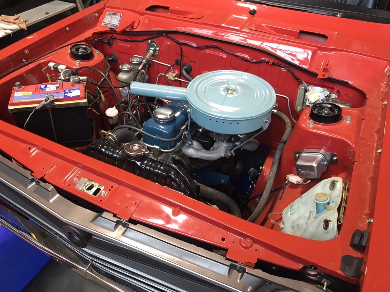
It's off the rotisserie for now! Needed to sort out the driveshaft which require the engine and gearbox to go back in.
Got the axles sent away to be shortened and resplined by 105mm a side. That meant I should make an attempt at swapping the Altezza LSD and the 4.1 CWP into the diff head. No pics because I didn't really know what I was doing. But for those that are interested I ended up using the LSD side bearings and swapped the Estima pinion bearings onto the 4.1 pinion. The Altezza pinion bearings where thicker which made the pinion gear hit the diff case. I couldn't get the wear pattern right because I didn't have any shims other than the two that were already on the pinions. Got it close enough for the time being, will buy some shims or give it to someone else to finish off.Decided to run Coil-on-plugs instead of the dizzy relocation kit, mostly just to keep the engine bay looking simple and clean. Got a set of 1NZ coils, I'm thinking of casting up an adapter plate for them.
Got the SQ engineering down-pull throttle linkage installed and got the accelerator cable shortened to suit.
Made a vacuum block off plate, since I hope none of that stuff is needed anymore.
Also at some stage I filled all the unneeded holes in the front radiator panel.Modded the accelerator pedal so it sits a bit closer to the other pedals, as before it was way off to the right.
Two-piece driveshaft all mounted now too! Think I got the angles sorted after spending far too long trying to work it all out. It's an Altezza driveshaft with the front half shortened (yes I know the front section u-joint phasing is 90° out).
In this photo you can also notice the sills have been strengthened (somehow missed that update somewhere). Used some 3mm angle and welded it the full length and ground back, so it's now really straight! Then boxed it back up to the floor, to try and stop dirt and moisture getting stuck in behind. Makes lifting the car along there way nicer!
This is the centre bearing support mount, much thought was also put into this!
Hopefully it's fine being welded to the seatbelt mounts haha. Still needs some doubler plates welded on to the other side of the tunnel.-
43
-
21 hours ago, kpr said:
going by your drawing. can you lift the rear of gearbox up and drop the pinion down so your angles are less aggressive ? the hanger will have to be moved up as well obviously.
Or possibly leave the gearbox where is. run first shaft up at 2.5deg angle from the gearbox, so the flange on end of first shaft is at zero deg. then drop the diff nose down to zero deg also. which should get you pretty close doing some rough maths. all depends if you can do that in your tunnel thoughreason for running a very small angle on the first shaft, is because it has no 2nd uni to cancel out how the uni accelerates and decelerates the shaft when run on an angle. sub 3 deg is fine. running a zero best, but yeh, uni will wear fast since doesn't have and bearing rotation. to much angle will cause more problems that running none.
as @Mof says the rear shaft angles need to be matched. ideally the less angle the better, long as it has enough angle to keep the uni's happy.
the nose of the diff will want to rotate up under acceleration. but from memory you are running rose joints on the 4 link? if so wont get bugger all deflection. so set up neutral will be fineSweet thanks man! I don't think there's going to be enough room to raise the gearbox up, could possibly drop the engine down a little if needed. I'll try and get the centre bearing mounted as high as it can, should be able to get it to 3° from the gearbox, and just have clearance for the handbrake.
Yeah the diff has rose joints on one end and urethane on the other, so I'll probably just set it up as neutral. -
32 minutes ago, Mof said:
Pretty much right. Centre bearing flange should be around 3° off gearbox flange like you say to make the ujs work. This can be up or down btw (you drew down).
Diff angle should be the same angle as centre bearing flange, but some say to angle it slightly up to counter suspension twist when accelerating. Personally I think yes for a race car, most of the info I've found on the internet comes from Americans setting up drag cars. I'd be pretty much bang on for a road car.
Awesome thanks! Gonna raise the centre bearing mount up a bit more so the angles aren’t quite as much. Most of the info on google just came up with raised 4x4’s haha
-
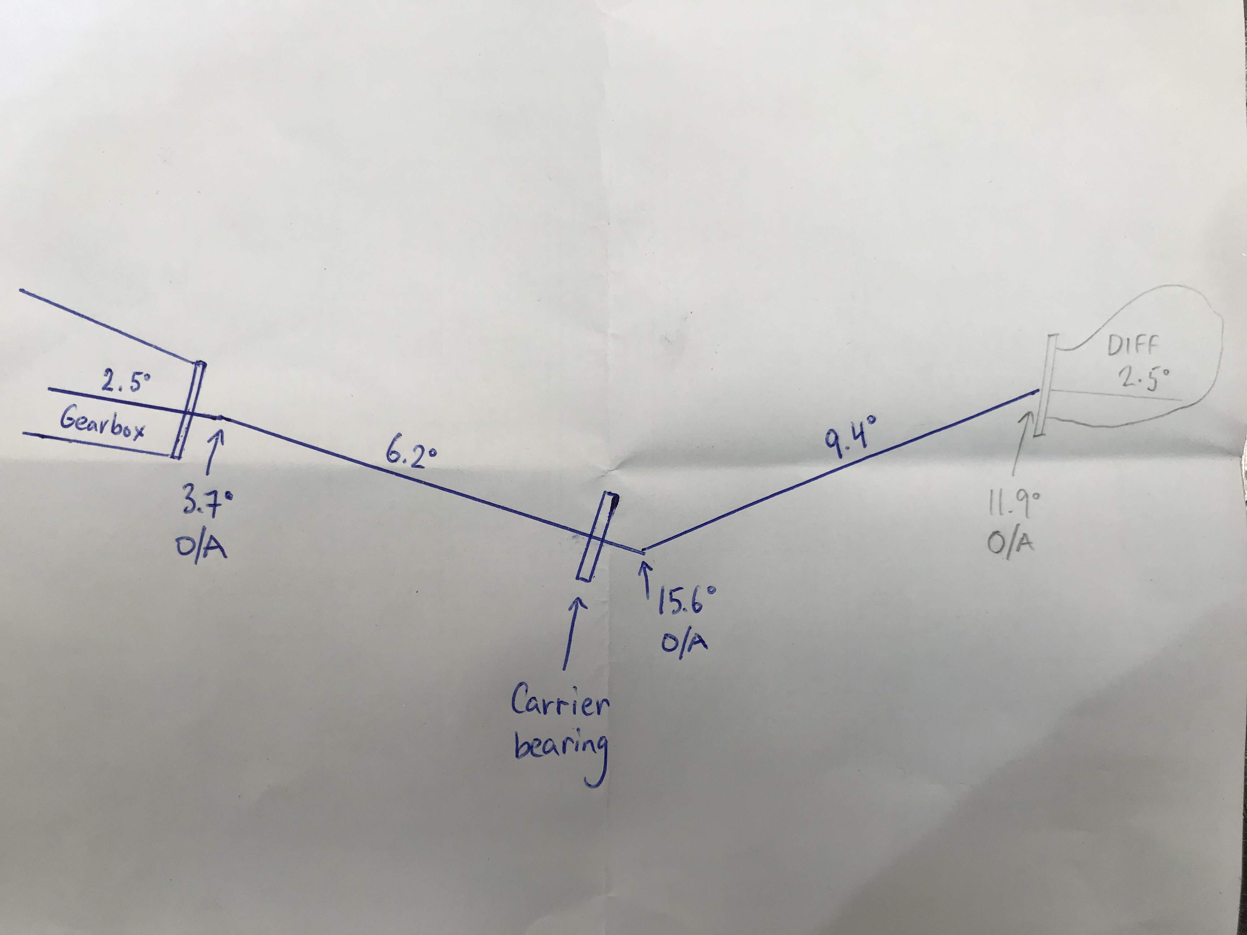
Hi, trying to figure out what angle to set my diff up and where to mount the carrier bearing in my Starlet.
From research I’ve found, most seem to just set up the first half shaft at 0° to the gearbox, and then setup the rear section the same as if it were a single piece driveshaft. But from what I’ve heard u-joints aren’t supposed to be operating at 0°.
The other way is to make all the u-joint operating angles (O/A) cancel each other out. From my understanding and calculations I keep getting, the pinion angle degree always equal what the gearbox is set at - gearbox pointing down at 2.5° and pinion up 2.5°. To me that doesn’t seem right? But maybe it is?The pen in the drawing is what I measured the angles at, with it sitting where I’d ideally want it mounted, but I can easily raise the carrier bearing up if needed.
The pencil is what I have come up with.Anyone know how to set it up?
-
18 minutes ago, Roman said:
Which reminds me @_Matt with a MAF remember its expecting all air to be metered from the maf, if you have setup a catch can it can act like a partial air bypass which can stuff things up too.
Thanks, no catch can or anything that bypasses the afm.
Gave the afm and pod filter a clean and rotated the afm around 90° so the sensor is upright. Maybe made a slight difference, will see what happens in the next couple of drives. The signal from the afm was pretty consistent at 1.08v at idle. The pages from a manual say it should be approx 1.1v.
Another thing is when I give it a little rev with the icv plugged in, it will drop down to about 1000-1200rpm and then take a few seconds to drop further to 800rpm. With it unplugged it goes straight down to 800rpm. Unsure if that’s related in some way? -
1 hour ago, Roman said:
Try putting the MAF in a longer pipe if you can. Or even just try rotating it relative to the bend after it.
MAF turbulence is a real ball buster and idle/low load is where it makes the most trouble.
See if you can borrow a factory airbox to test fit even if just for idling.
Cool thanks, will check it out tomorrow! There is a slight pie cut bend right before the airflow meter, so maybe that’s causing an issue
-
1
-
-
Have swapped in another ecu and it has made no change. Have also had the idle valve unplugged for a while and it is better, sits somewhere around 600-800rpm pretty much all the time now. Just doesn’t like starting when cold that much.
Blocking off the idle valve inlet kills the engine, so I assume that means no air is coming from anywhere else.
Voltage from the ecu to the idle valve solenoid is 12v and decreases when revving, which is weird because it should be 6-7v when cold and 7-10v when hot.
Had a thought the temp sensor could be bad but that is outputting the correct voltage.
No idea what else to check! -
- Popular Post
- Popular Post
Both back sections of the floor done. Has an exhaust tunnel through it to suit a duel 2" system, should be able to tuck it right up above the chassis rails.
Sills and chassis rails are now the lowest point in the middle section of the car.
Made a rear strut brace to strengthen the upper shock mounts and to accommodate the extra load of coilovers.
Made the exhaust tunnel through the front foot well too.
Notched out the crossmember above the diff for clearance.
Made a mount for a Wilwood pedal box, need to figure out where to put the reservoirs and move the accelerator pedal over a little.
Raised the spare wheel well up 60mm to fit a larger fuel tank.
Was a good chance to also drill out the spot welds on that centre mount and tidy up the rust that was forming in between.-
49
-
1
-
52 minutes ago, Grotty said:
not a stepper motor, did you test on the bench after cleaning it?
No I didn’t, but I did change the throttle body to a whole different unit which included another idle valve. The new one looked to be in better condition on the inside. Would of thought there would of been a slight difference on how it runs after changing the TB, if the issue was somewhat related to that.
Will pull it off and check though. I will also check what voltage it’s receiving during different times. -
31 minutes ago, Grotty said:
is the idle valve a stepper motor on that?
The AAC valve? If so, I’m not too sure, quite possibly?

-
Pulled out the ecu and opened it up. Everything looked good.
Only problem I could see, there was a dent on the under side located where the JECS logo is in the lower left. It was pushed in enough for the cover to be indented from the board and those pins coming off the plug.
Maybe that has caused something to short out? Wasn’t anything noticeable. -
3 hours ago, thegreatestben said:
Ling post but I would chuck some $$ in a hat to see this thing get an aftermarket ECU.
Also keen on that, but that’s a lot of $$$. Have a bellhousing and clutch setup to suit a w series manual box, which will make it way more fun to drive!
-
4 hours ago, fuel said:
Pull open the existing CPU and check condition of the electrolytic capacitors - if you see any bulging or signs of leaking then they could be your problem.
Ahhhh will have a look, thanks. Knew this was a common issue with 4age 20v Ecu’s. Didn’t think to check on this
-
RIP Accuair
-
 1
1
-
-
Thanks guys, will have a check over all that. I’m pretty sure the butterfly/throttle linkage is closing properly, as I gave it a push down and the idle barely drops at all.
It is running a vacuum brake booster and the other couples of vacuum lines are blocked off.
I have been thinking it has been electrical for awhile, because of the power off and back on, then it comes right, but trying to find another ecu has proven a bit difficult. -
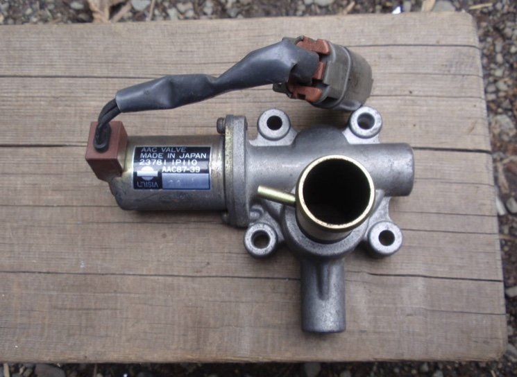
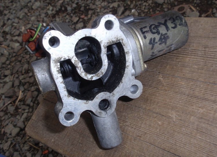
Hey @fletch, I have cleaned out the AAC valve and it made no difference.
Then I got a whole new throttle body, which included a different AAC valve and bolted that all up. Again made no difference.
I did notice the coolant isn’t hooked up to flow through the throttle body. I don’t think that should be causing this issues though. I did also back the adjusting screw that the AAC valve pushes and moves the throttle linkage up all the way out, so it shouldn’t idle up from that anymore. That also made no difference.
Another thing to add is when you give it a decent rev at idle it will start idling even higher, not sure if it does it all the time or just when it’s already idling high though.


Palmy Monthly Meet - Discussion
in Lower North Island Region
Posted
New meet up! This time we’re gonna try out Shake Out on the 20th Oct at 7pm