Guypie
-
Posts
854 -
Joined
-
Last visited
Everything posted by Guypie
-
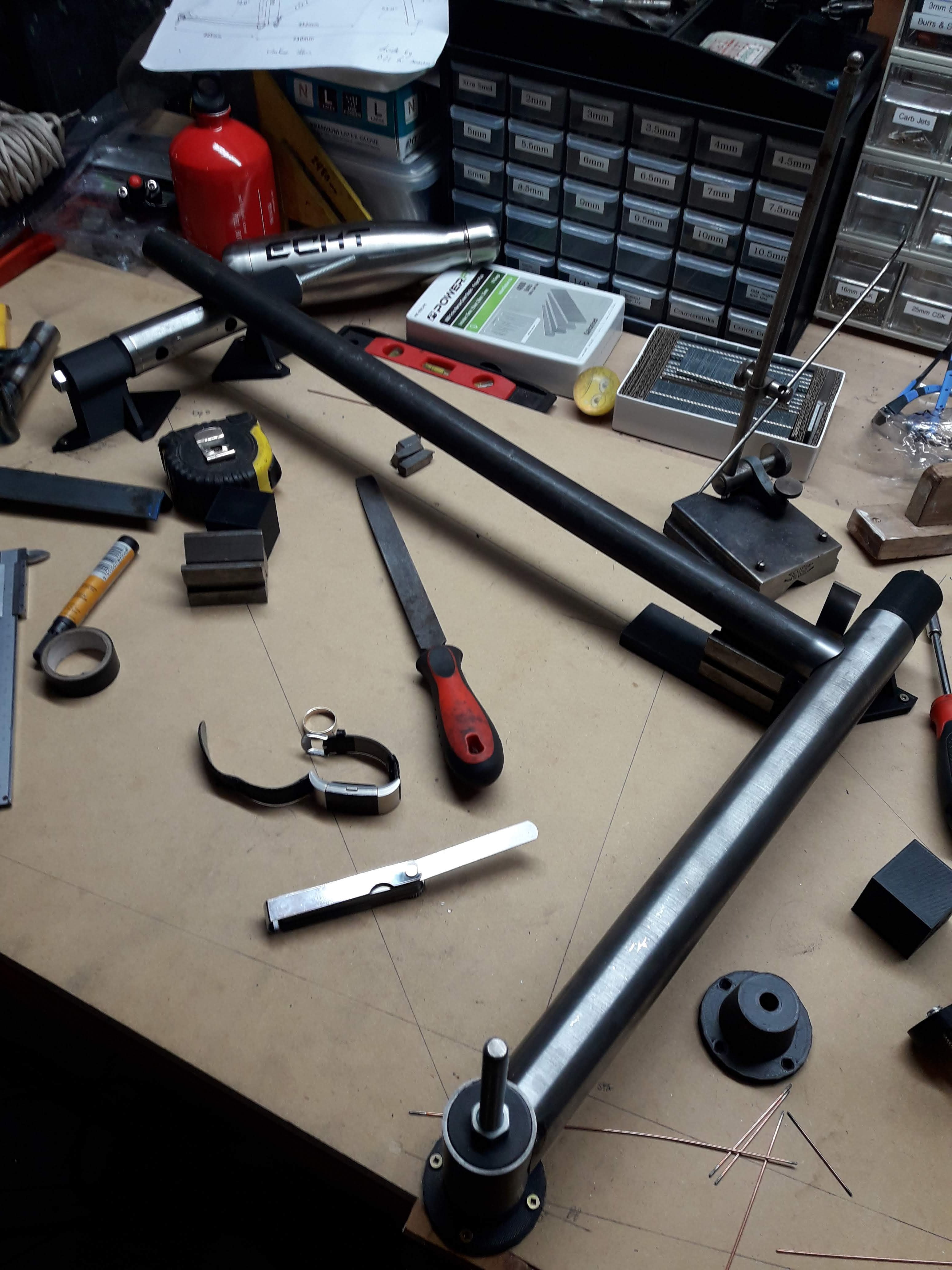
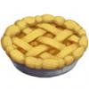
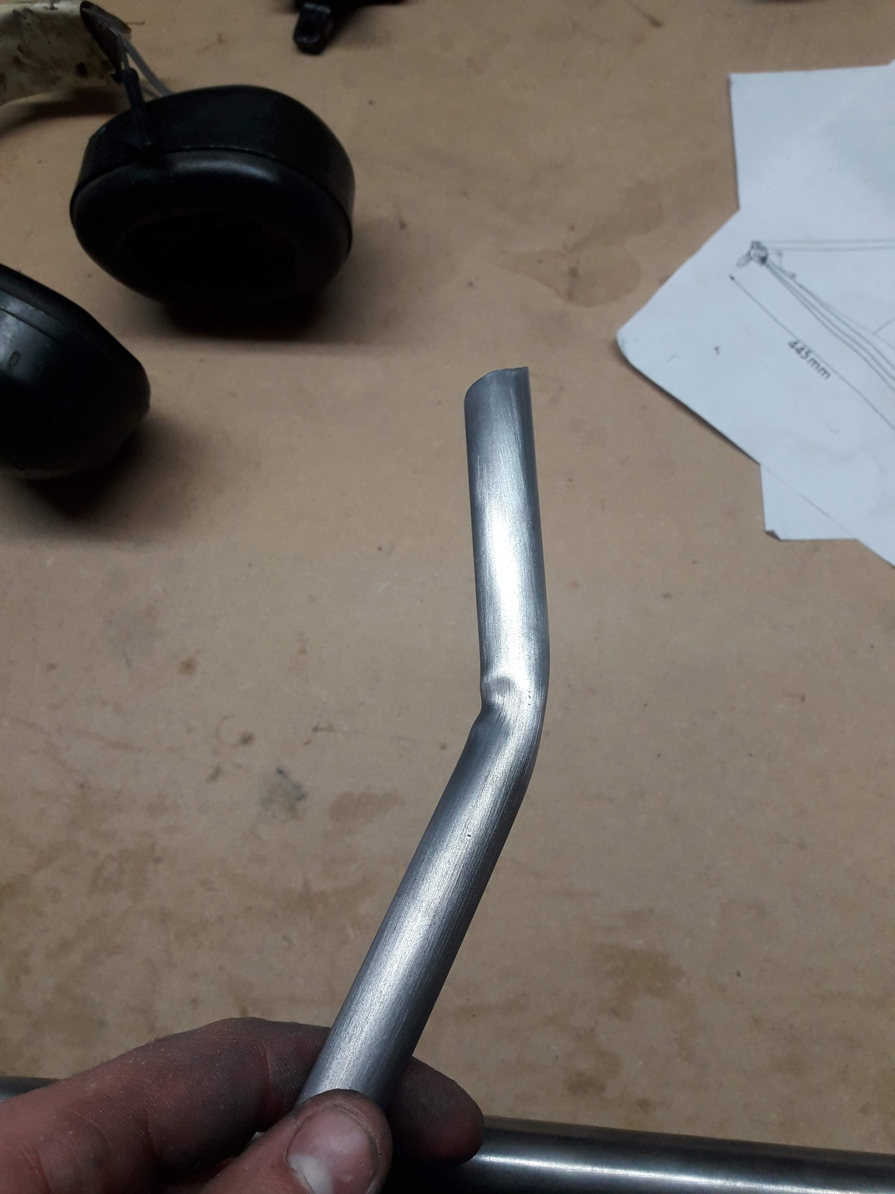
Next up is getting set up for bending seat stays. I bought a 3 ton arbor press cause I figured it would be nice piece of kit to have for fabricating things. The seat stays are 5/8" tube .049 thick (about 1.2mm, most of the other tubes are .035"/0.9mm for reference) so I needed to make some tooling for the press to bend these, hopefully without kinking. I turned some form tools out of 51mm ali I had lying around and then turned off the bottom of one piece for the press tool. The piece to the left I needed to cut in half for supporting either side so I resorted to the scary tablesaw of death. I screwed it down to a sled with a piece of angle iron and hid behind the sled while feeding it through. My gamble with tablesaw russian roulette paid off and the part was cut fairly cleanly, though not quite as even as I had hoped. Still, didn't really matter for what I had in mind Gave it a press and the bend came out... ... with a horrible wrinkle on the inside. Sigh. This photo actually makes it look far worse than it is, so I just went ahead and used it anyway considering this piece of material is about $30 worth @ 460mm long. For the second stay I did some file work on the upper tool to increase the radius of the bending form and it was much better.

-
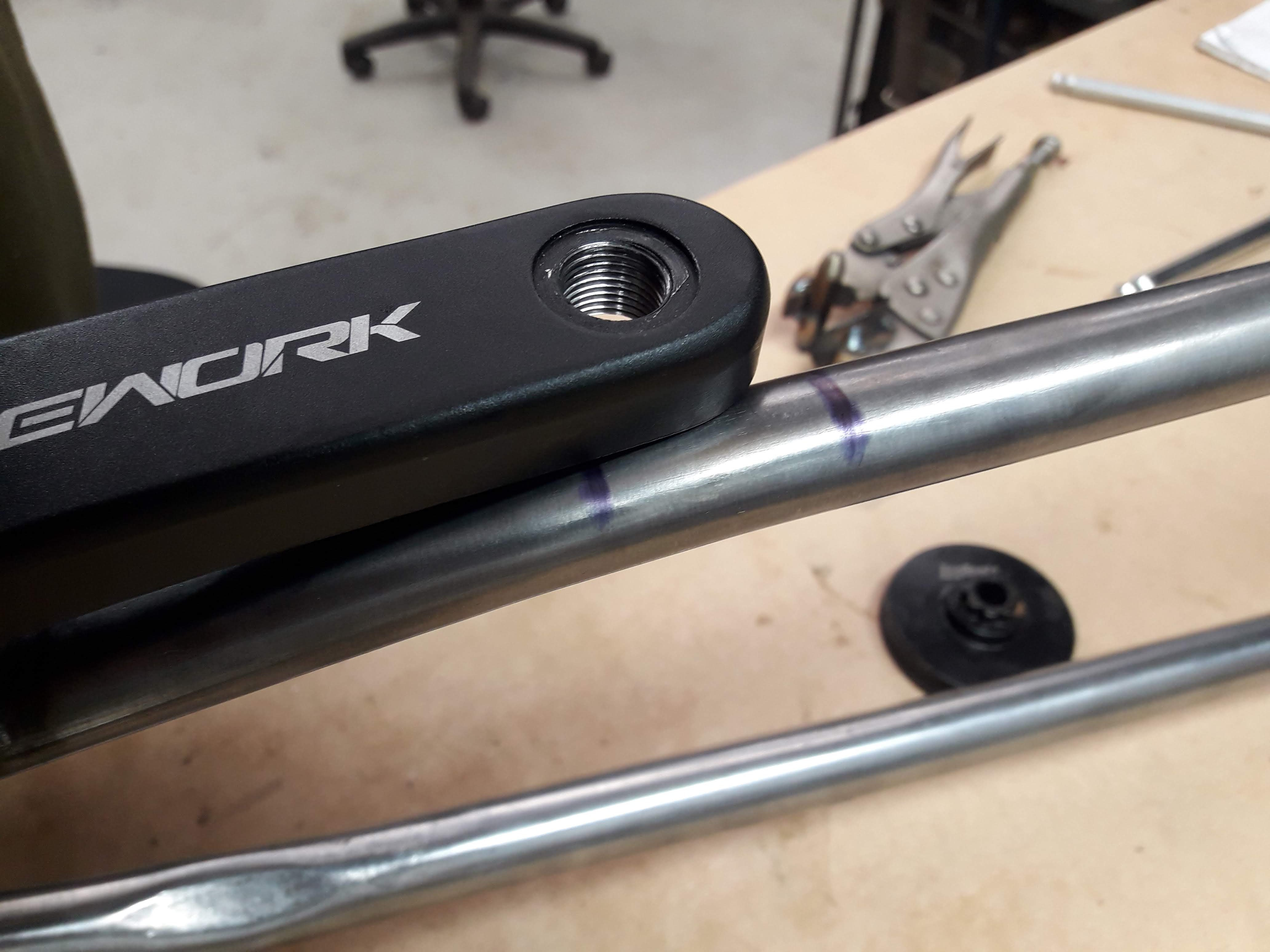
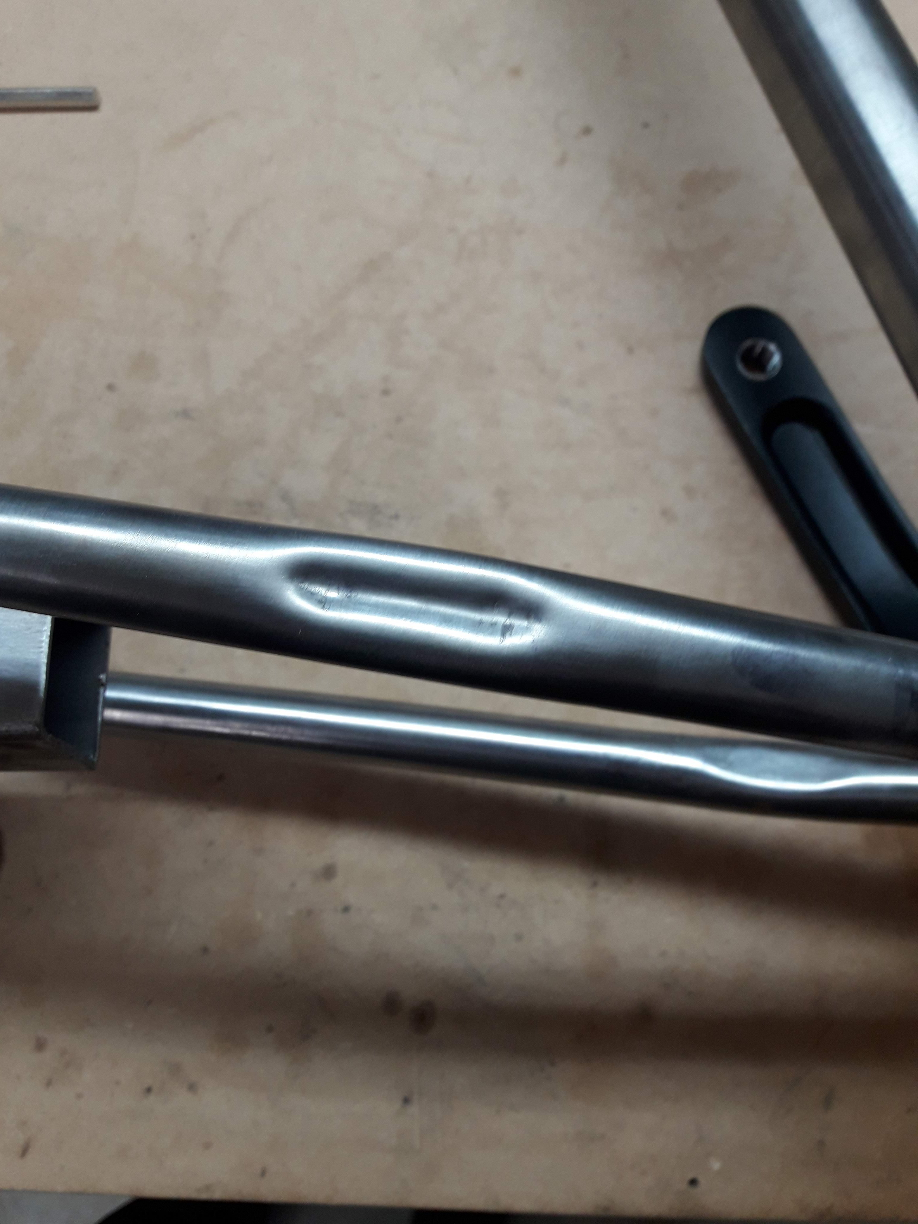
I welded on the chain stays next, then decided to pop a crankset on to see if I managed to stuff up the chainring clearance. Turns out the chainring clearance was fine but the crank arm on the drive side had a slight issue: Oh dear. So I put together a dimpling too to make a bit of clearance like so: A bit of a squeeze and things were good to go! I might need to revisit this later as under load it might flex into the crank arm but thats a problem for future Guypie.
-
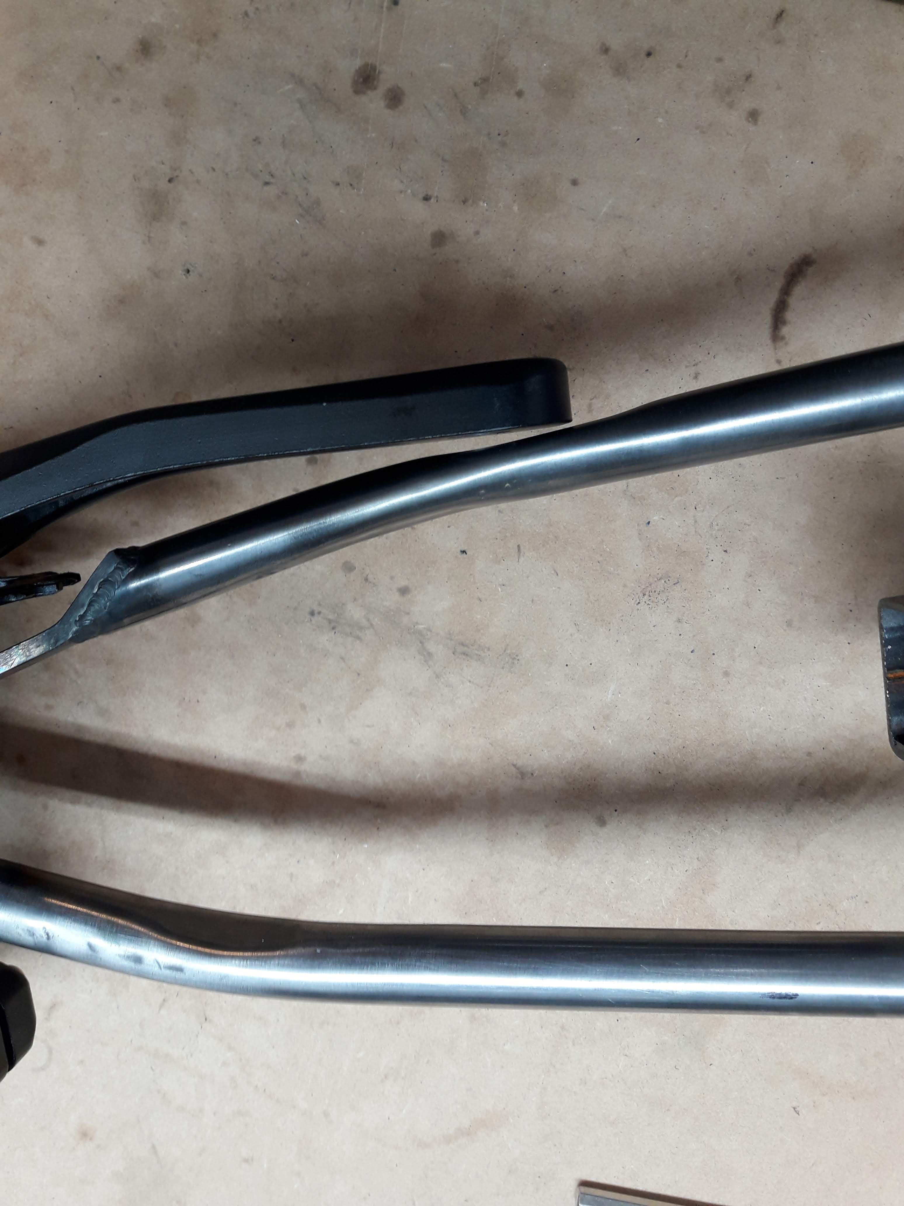
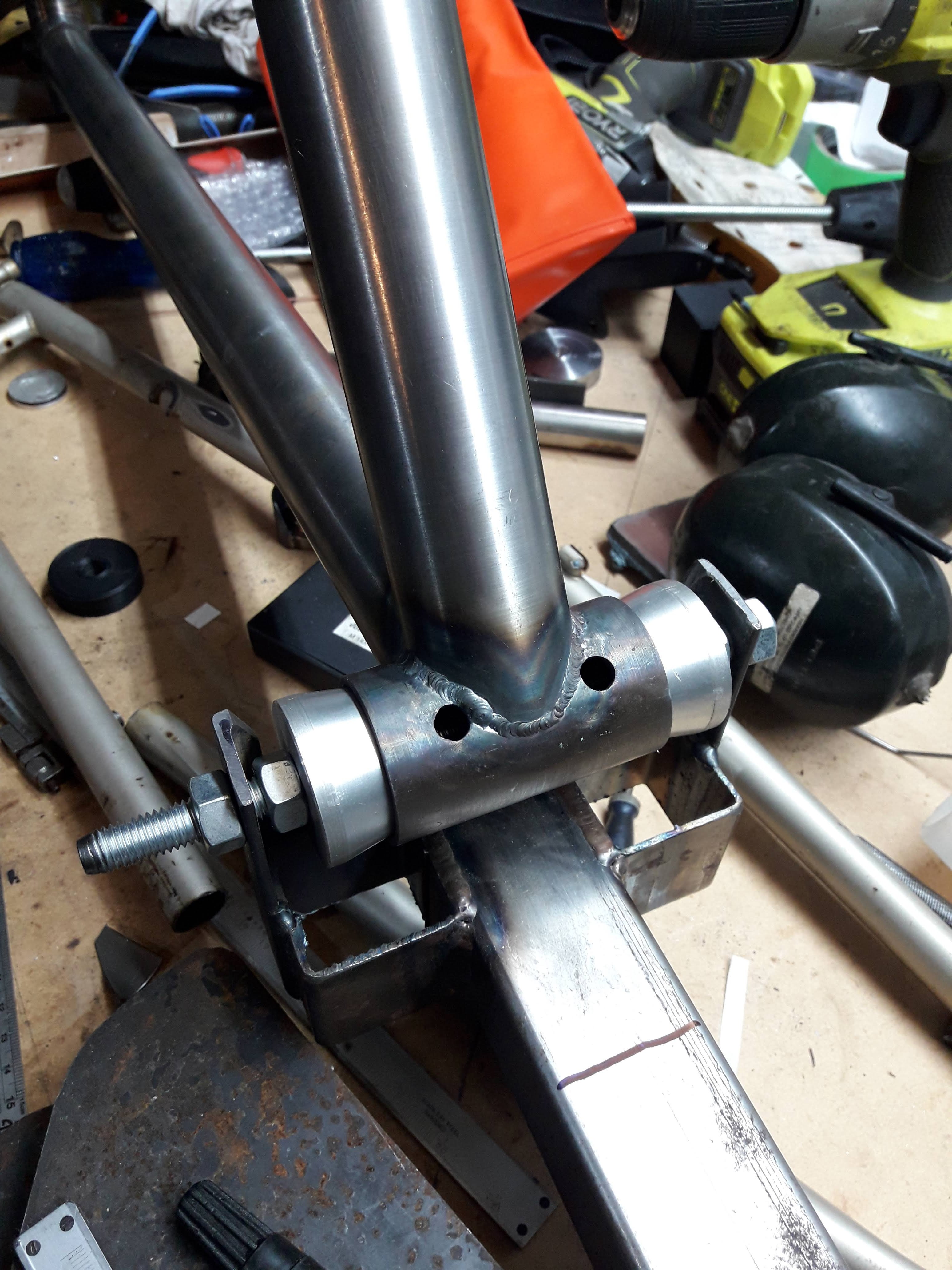
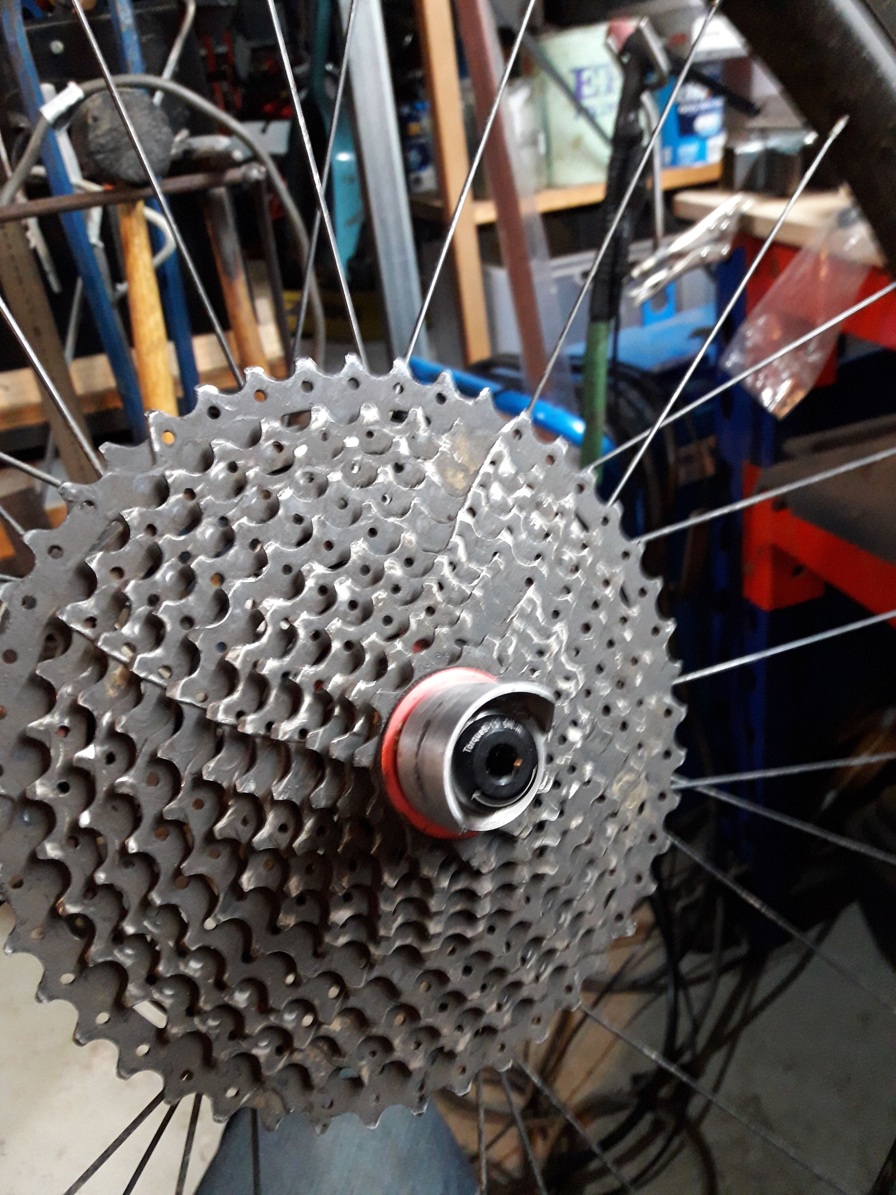
I started on the non drive side chain stay. It was a seat stay donated by the vintage marin (RIP) I gave it a little bit of a tappy tap with the hammer on the inside of the curve to tighten up the radius and tacked it in place I figured I should check for any clearance issues before going any further so I unbolted the rear axle and rotated it in the jig then threw the wheel in and gave it a spin: I forgot to take any pictures of the drive side stay before I tacked it in place. It is a chain stay from the marin which interestingly had 3/4" chain stays and seat stays, and I made a bridge to clear the chainring out of a piece of hardox 450 4mm plate. Hopefully the hardox works out well, 4130 plate is ludicrously expensive. the piece of wood in the middle is a very rough and ready tyre clearance gauge to make sure I don't make any silly mistakes while tacking it together
-
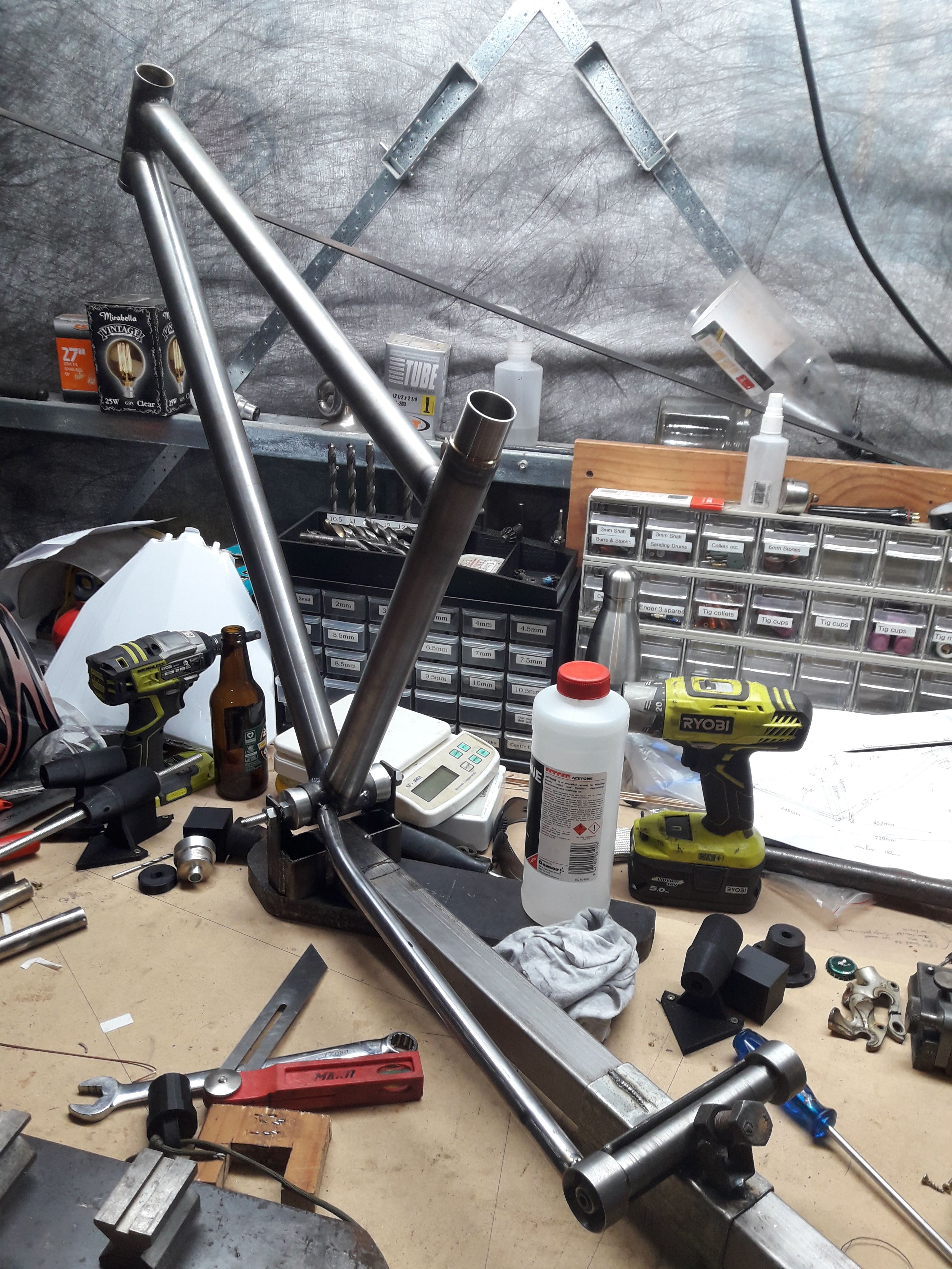
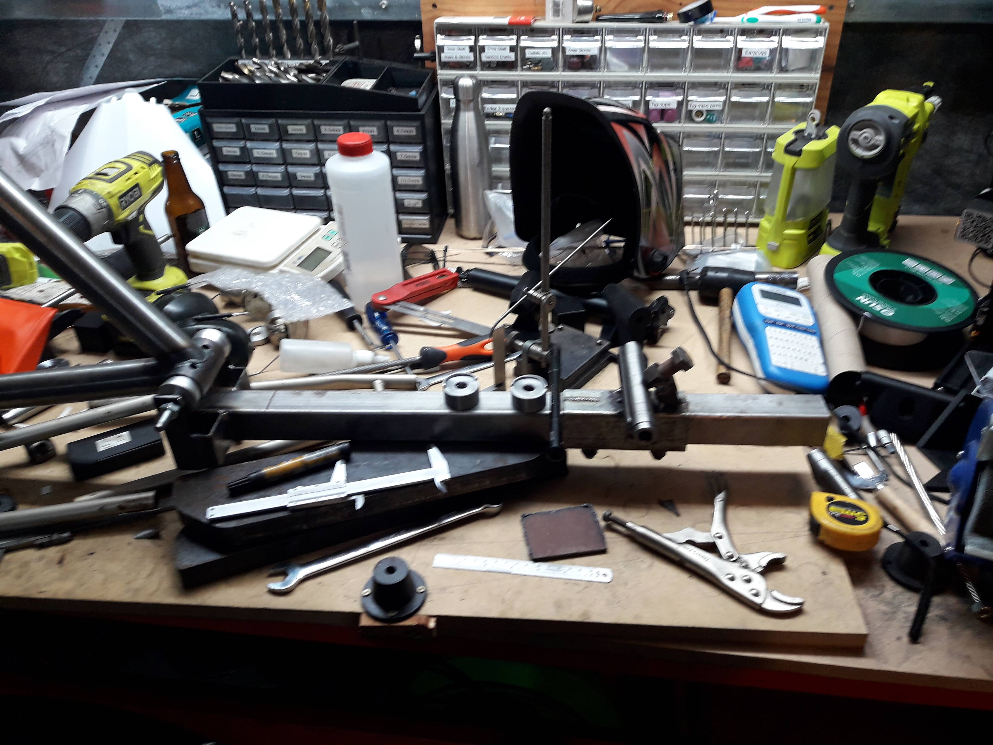
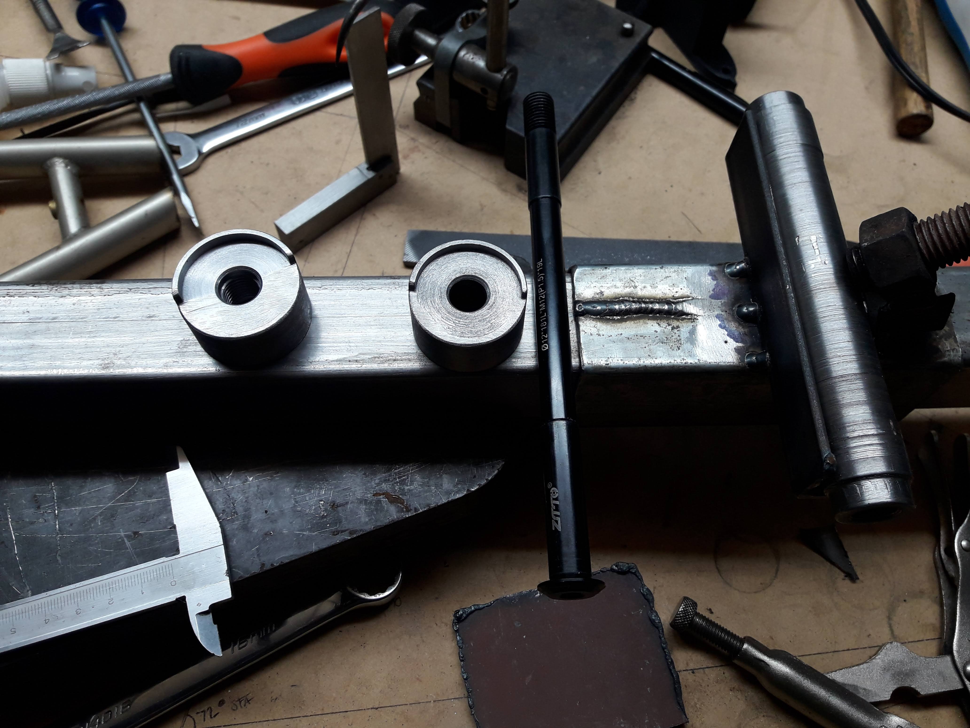
I have managed to get a bit more done on this in the last couple of weeks. Here is a terrible picture of my BB to rear axle jig. I won't be using this again, for the next build I will make a proper jig. But it got the job done. I filed the bottom of the lip of the frame ends flush so that when you have the bike tipped upside down to pop the wheel in there's a ledge for them to rest on. The horrendous surface finish on the dummy hub in the jig is a bit weird. I have a bunch of lengths about 300mm long of some sort of medium tensile steel that was the offcuts of a CNC job from a friends workshop. I cannot figure out how to get a decent finish on it, it just always comes out with a very torn up looking surface. I have tried a few different tool geometries, different feeds and speeds, always comes out looking like balls. BB is centred on cones. The other reason I will be going with a new jig next time around is that there's barely any space in here for the 68mm BB shell. I only used that size because that's what the old marin had. Next time I think I will buy a new shell in 73mm. (or maybe 83mm...) Also those 2 holes from the old chainstays were a pain, I had to patch them as the new stays didn't line up with the holes. not sure if I took a photo but it looks a bit of a mess in there. fortunately that little nook is always just jammed full of mud anyways so as long as I don't clean the bike it should be well concealed.
-
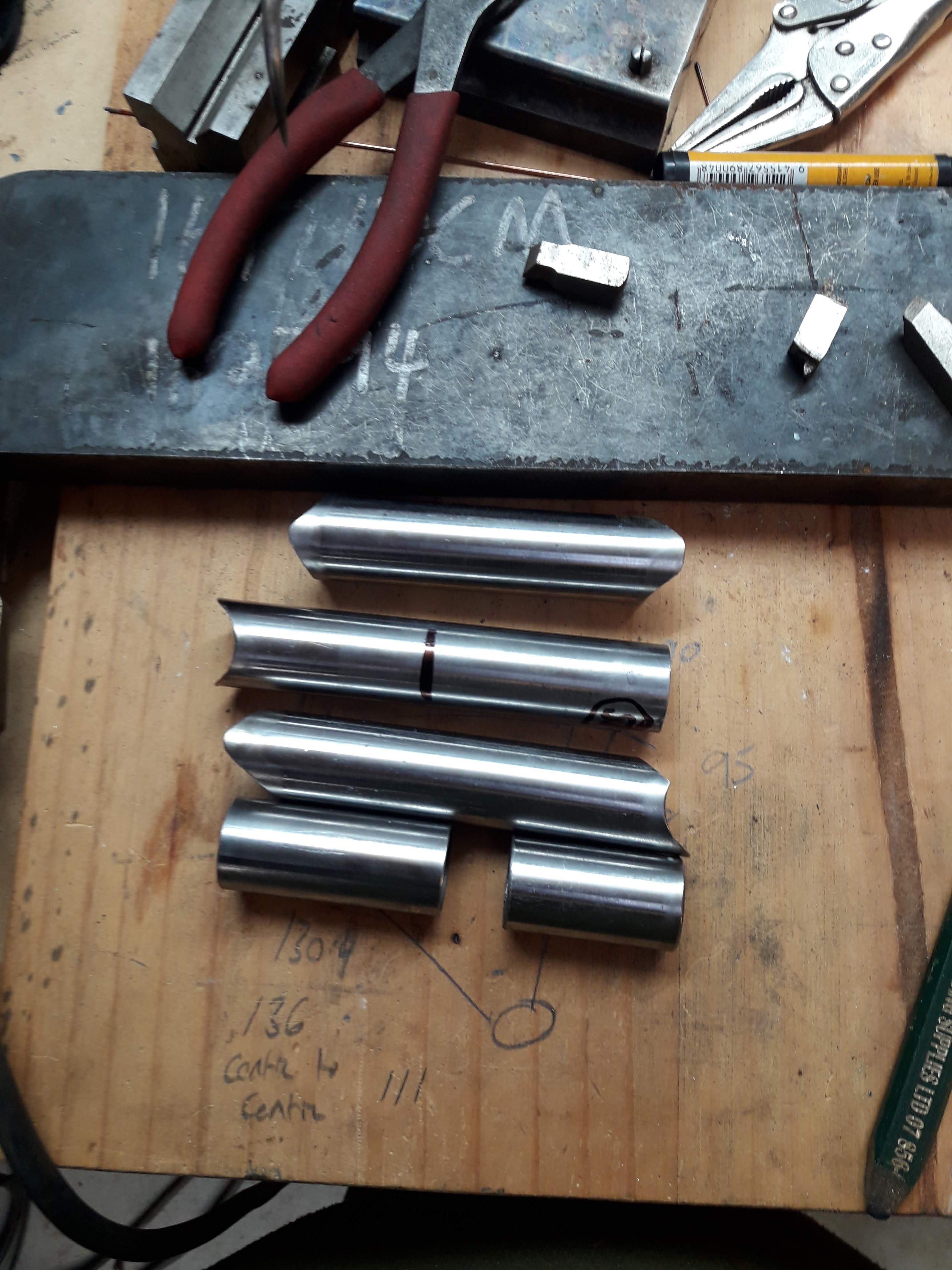
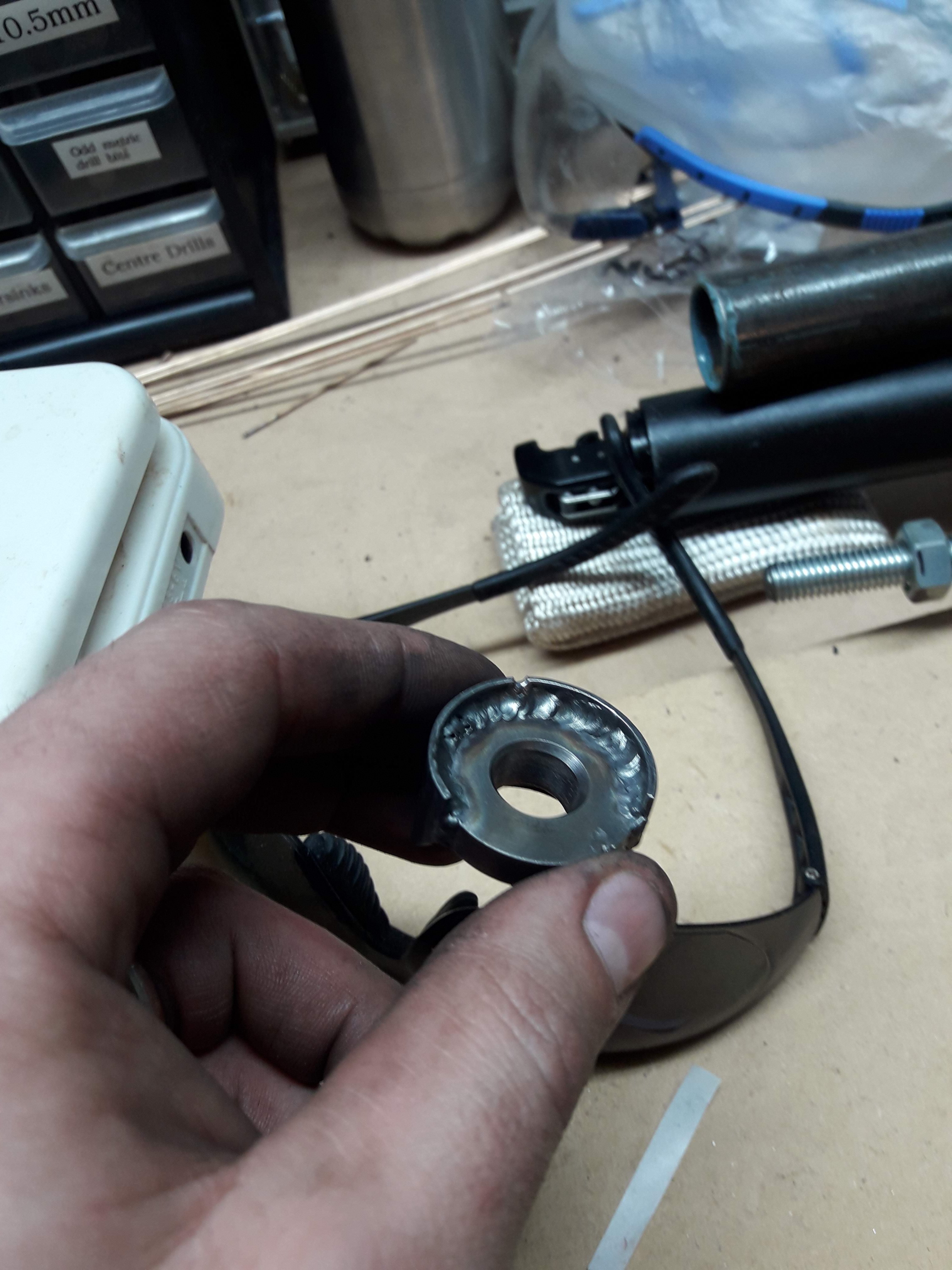
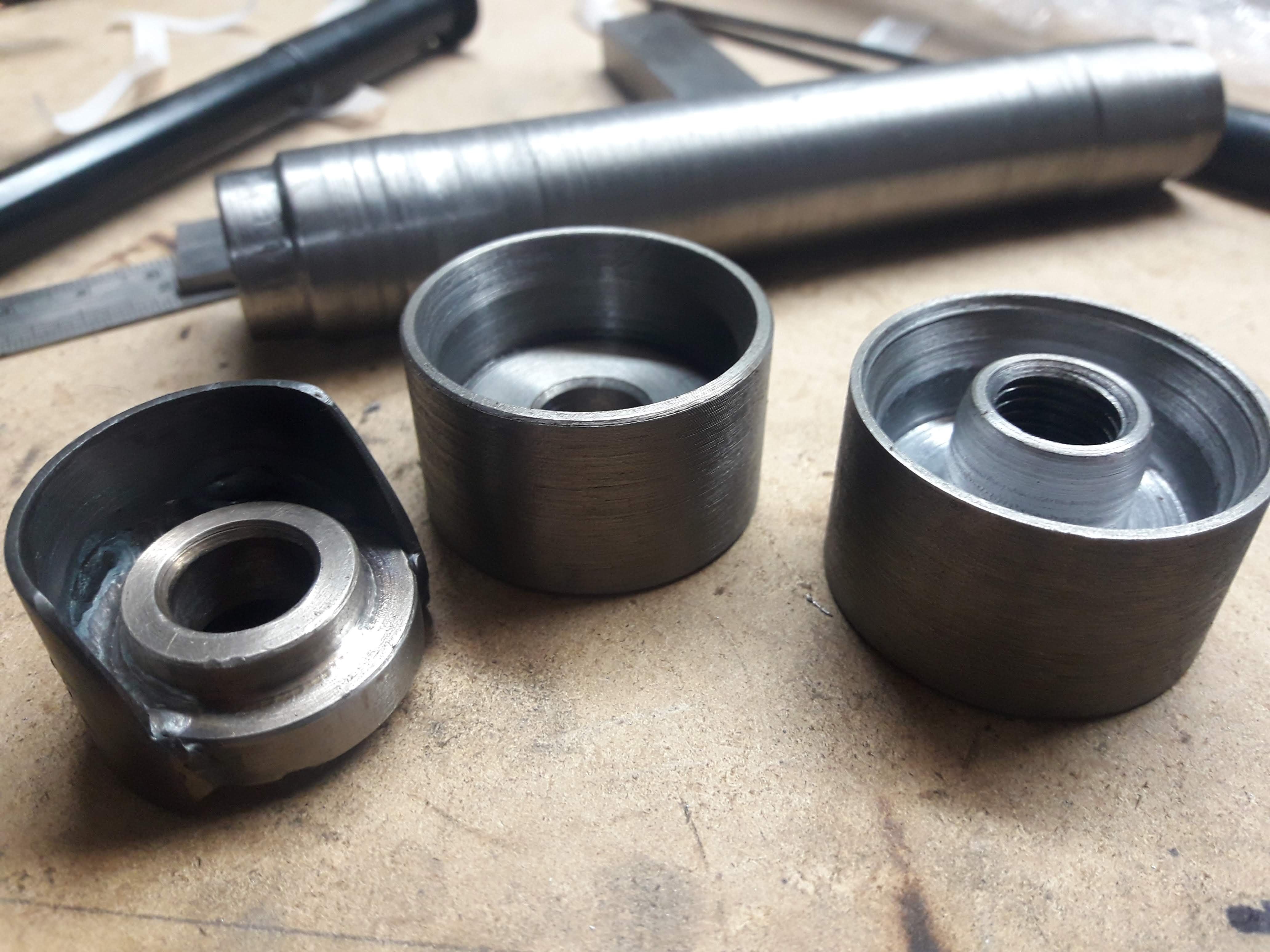
And it came out like this. fairly yuck after heaps of fileing/sanding/scotch bright it looked a bit like this: Its kind of ok, but I'm not really happy with it. So with about a days worth of work in it I decided to scrap it and start again. Today I spent most of the day turning these out of some mystery steel from my box of offcuts: They look a bit like oldschool skateboard wheels. Much more happy with the outcome, I need to cut the shroud parts down to the correct size so I will probably go get a nice new file tomorrow and just do it by hand. I had a little test run on the lathe putting it off centre with the 4 jaw chuck. It would work but it was mildly terrifying, not to mention if the jaws slipped on the workpiece it could turn it to scrap metal real quick
-
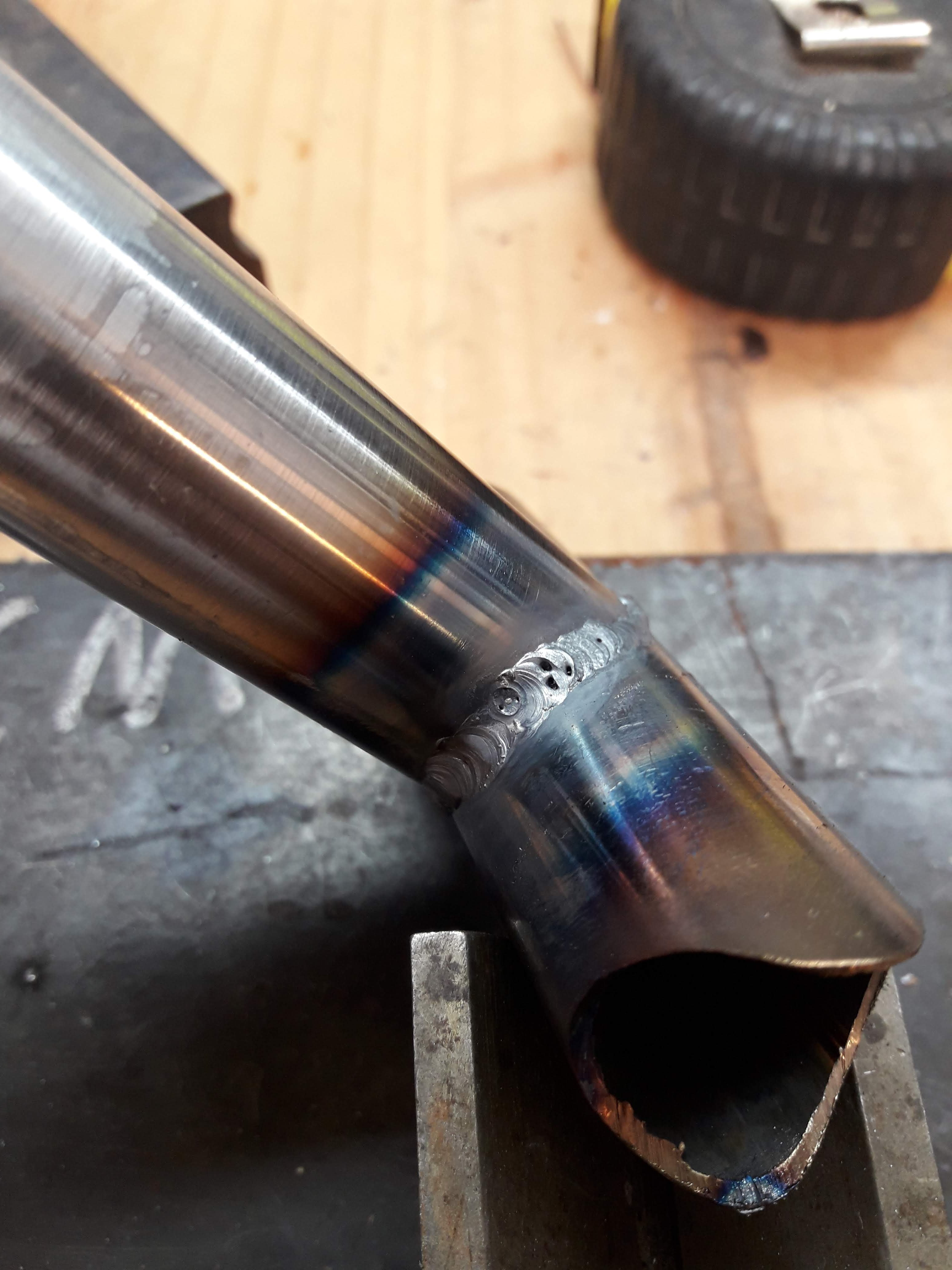
After a few hours of work (not even kidding, gotta go real gentle on the old girl!) I came out with these: I used a piece of stainless tubing I had to make the shroud part and tacked it on then remembered that stainless is poos and will go all sugary on the backside if it gets too hot as below. So I filed off the tacks for round 2 This time with 4130 tube: Then I welded it up...
-
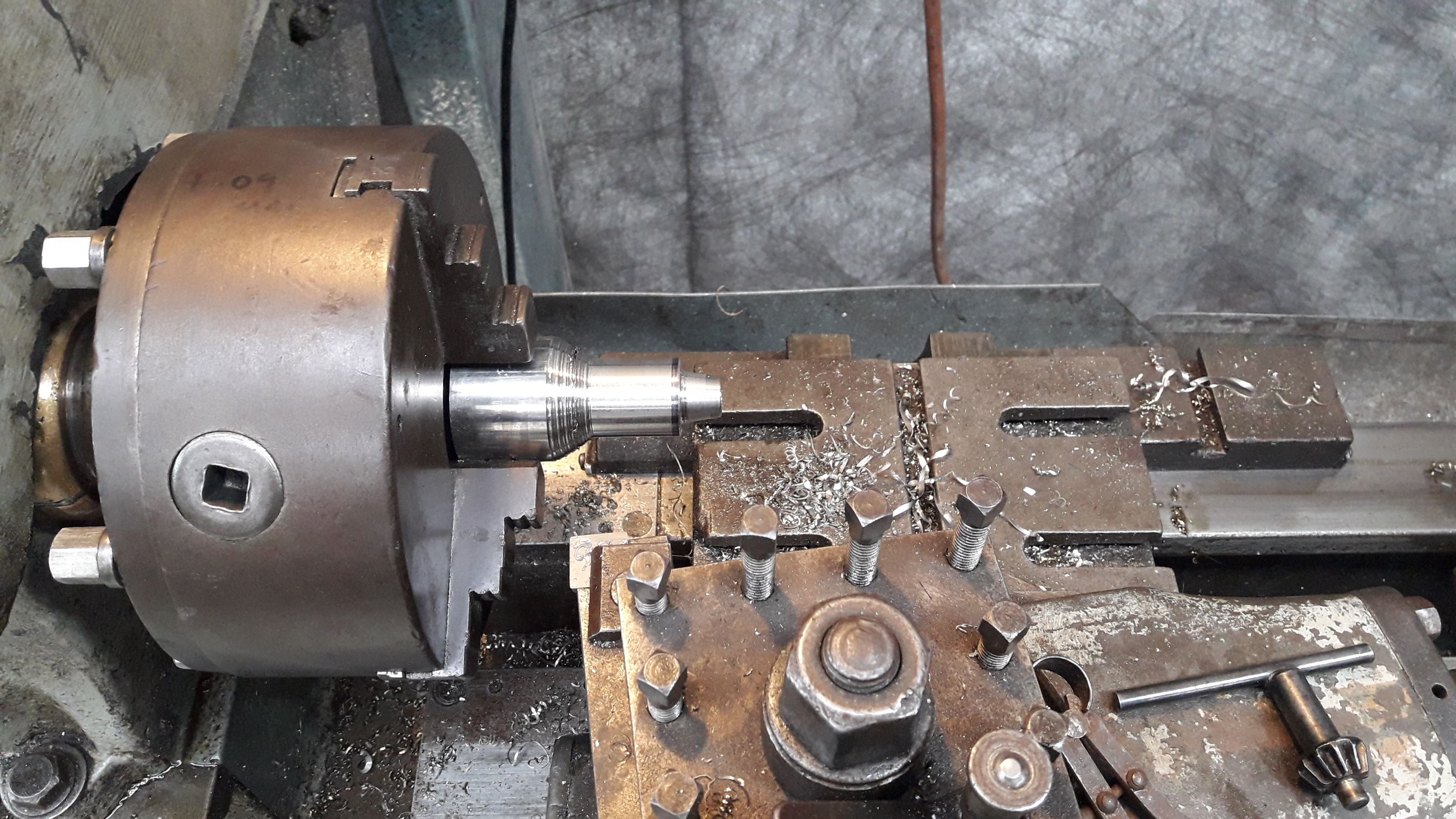
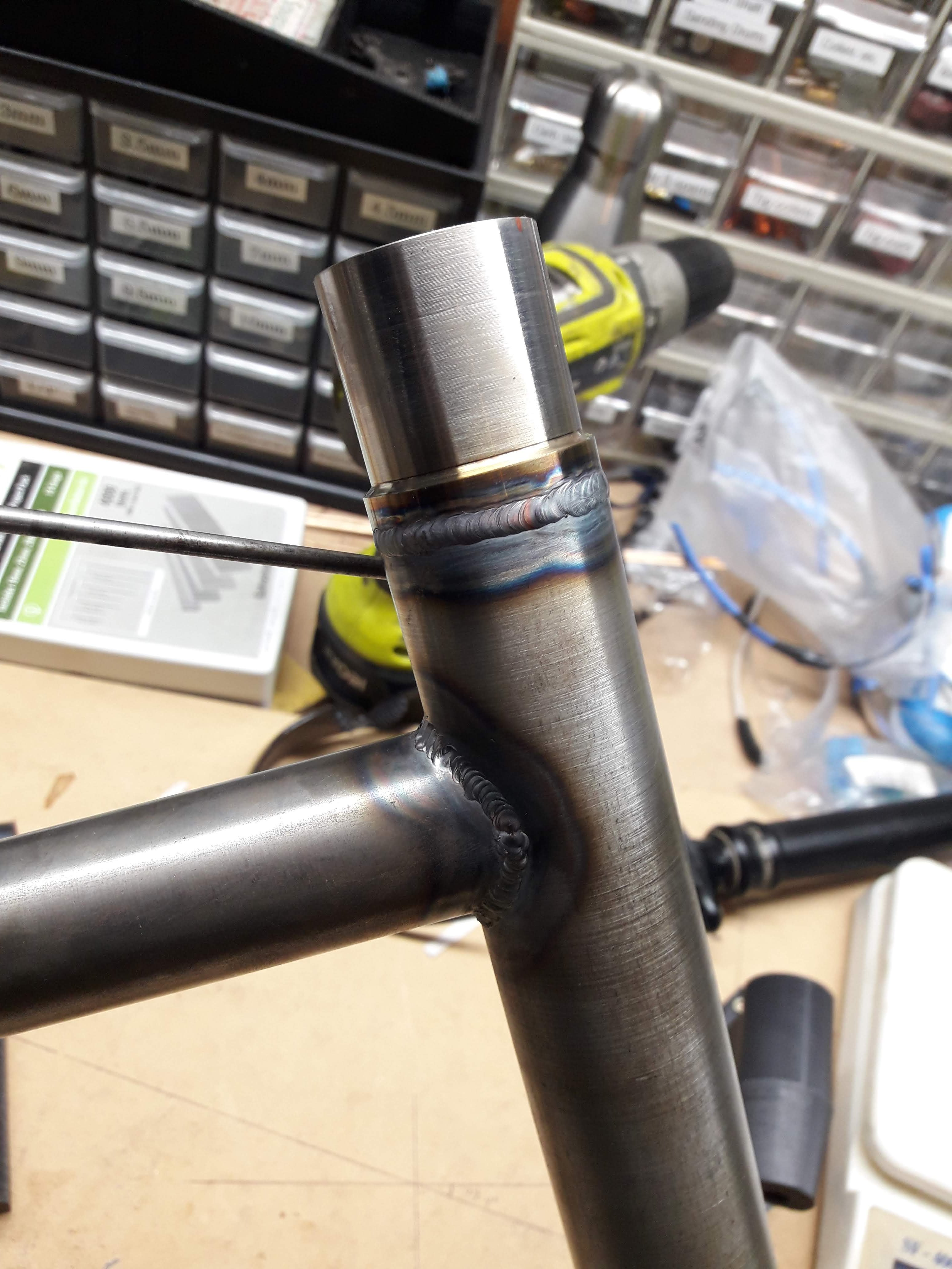
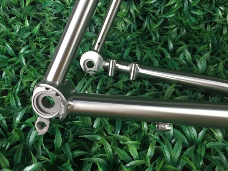
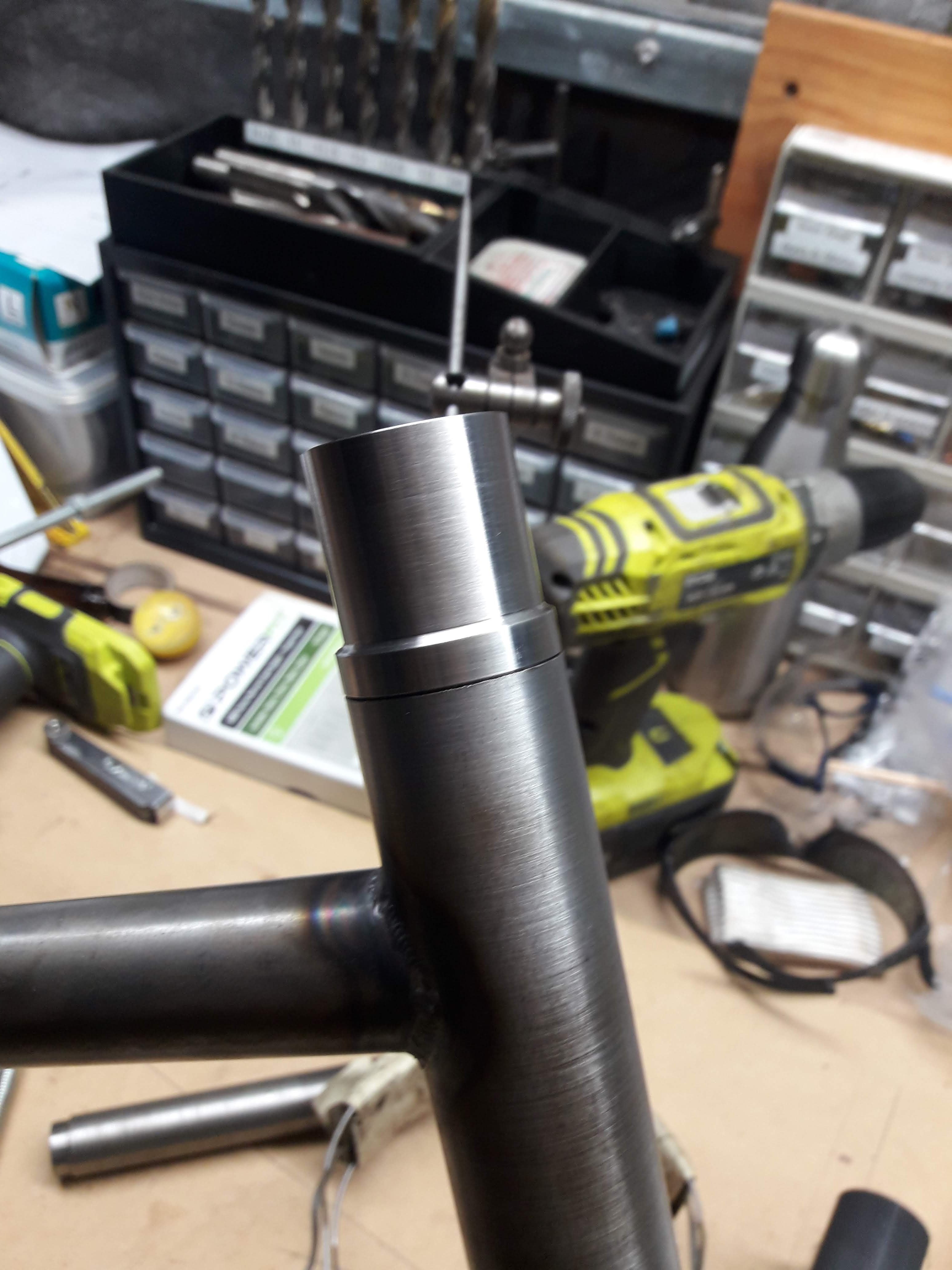
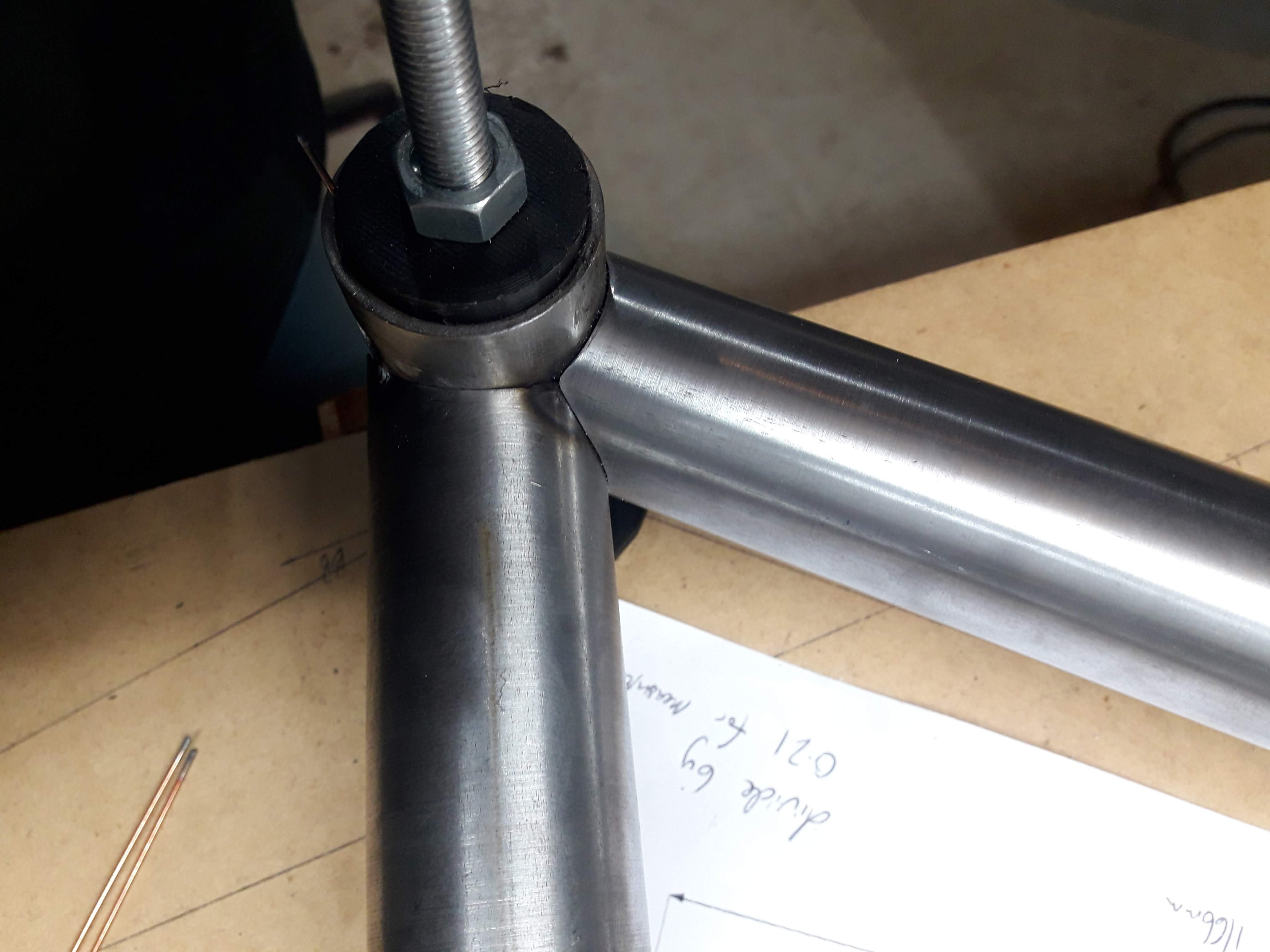
Aaaaaand welded in place: Will need to send a reamer down the tube as internally it has gone kind of hourglass shaped from welding it in place. I threw the frame back in the jig to see how far/close it was to original dimension, its pretty darn good! Using the height gauge it looks like in relation to the headtube the seat tube about 0.5mm off line. Which I don't think will be noticeable at all in the end product. I gave the lathe a cleanup at this point as the swarf overflow was starting to get sucked into the leadscrews which is generally a bad time This is my old lathe, its a selson probably from the 1920s. The headstock bearings are absolutely stuffed and it can only turn anything by virtue of being heavy. Too much cutting load and it starts to vibrate like crazy as the spindle "rolls in the slop" if that makes sense. I actually have another newer much better lathe on the other side fo the workshop, but it needs 3 phase that I don't currently have. To make the dropouts my plan was to turn some centres for the axle and weld them into a bit of tube, then cope the chain stays and seat stays to weld to the dropouts. kind of like this: but a bit more simplistic. So I got a chunk of stainless and started whittling it down...
-
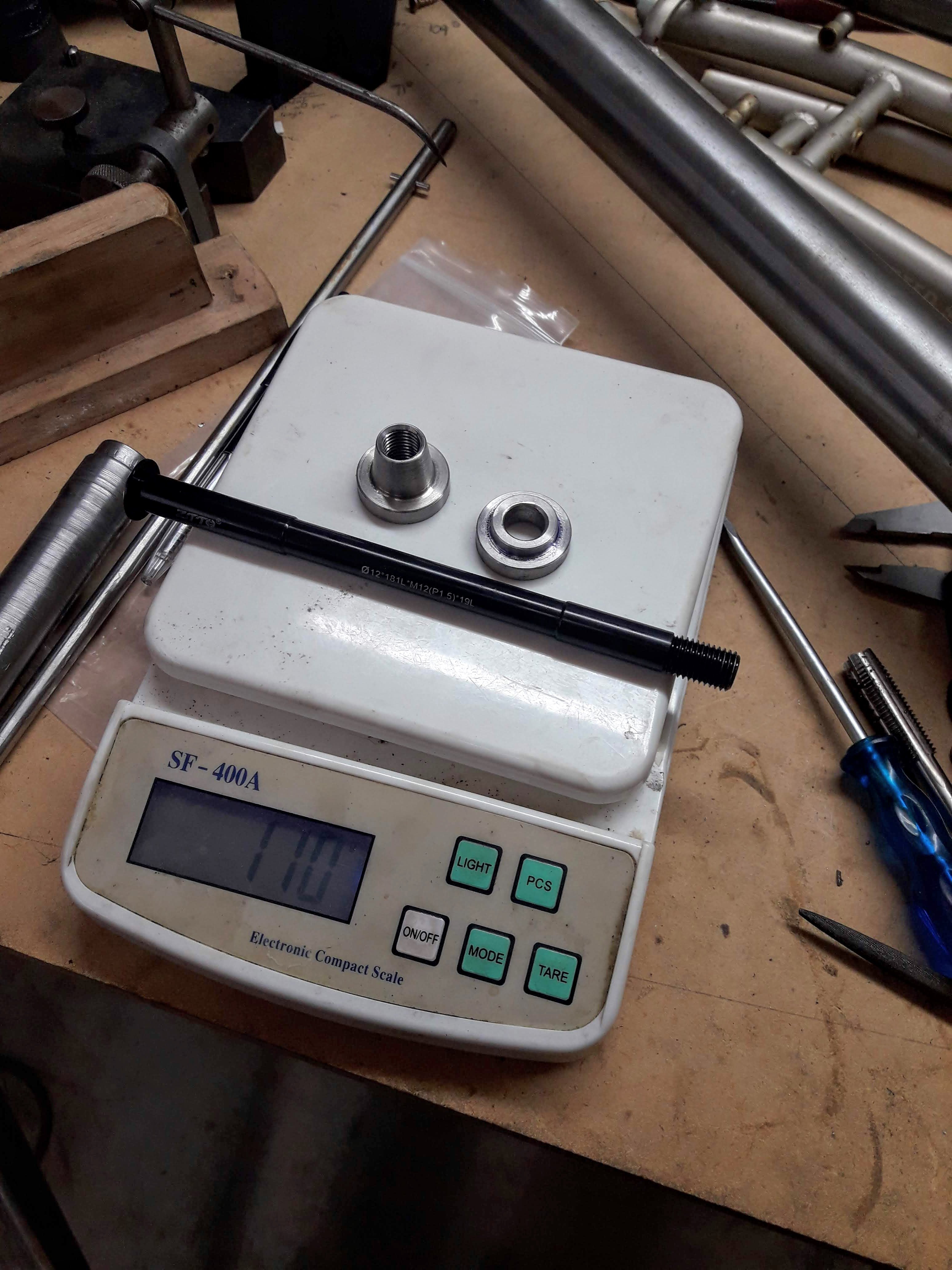
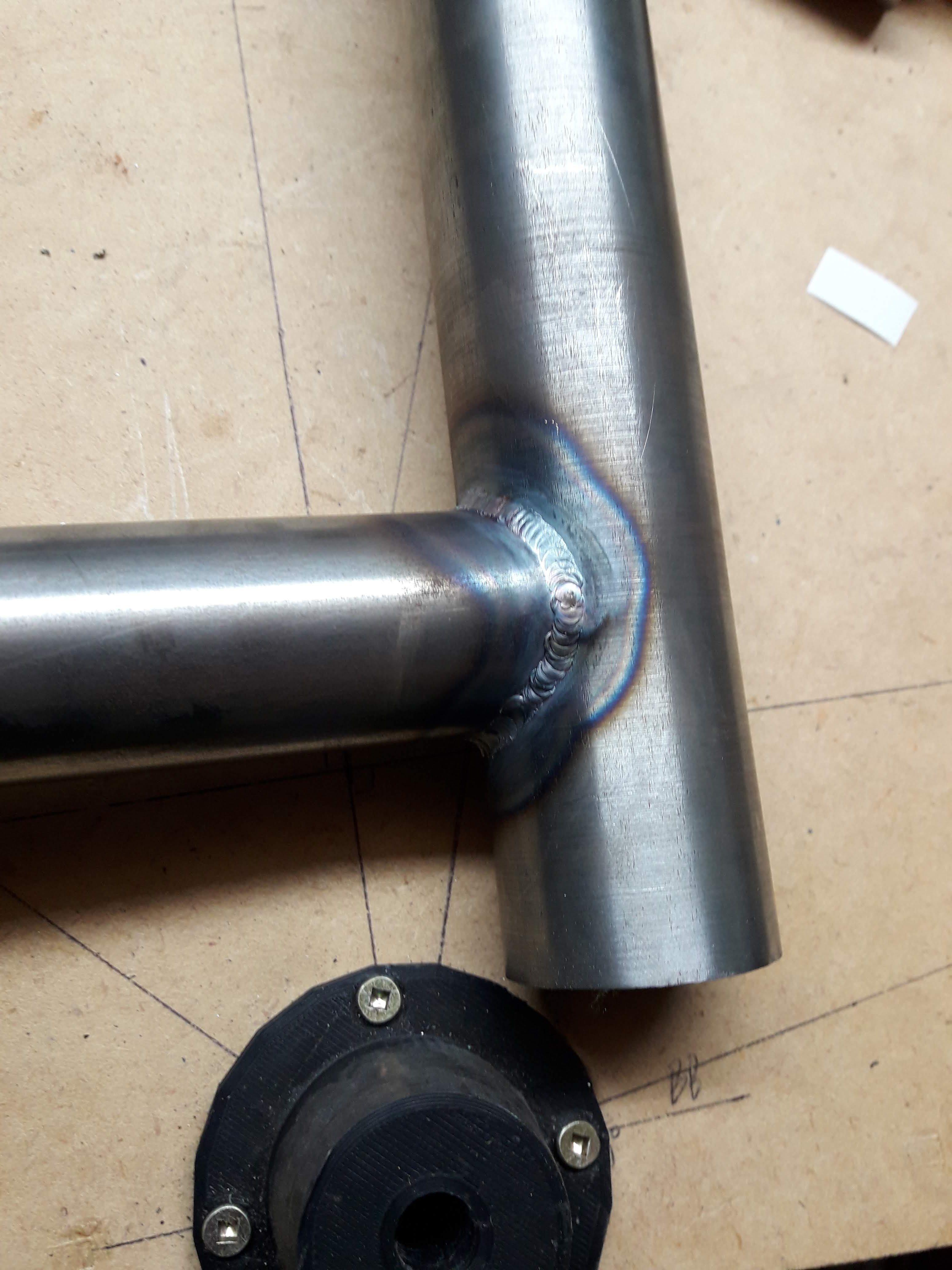
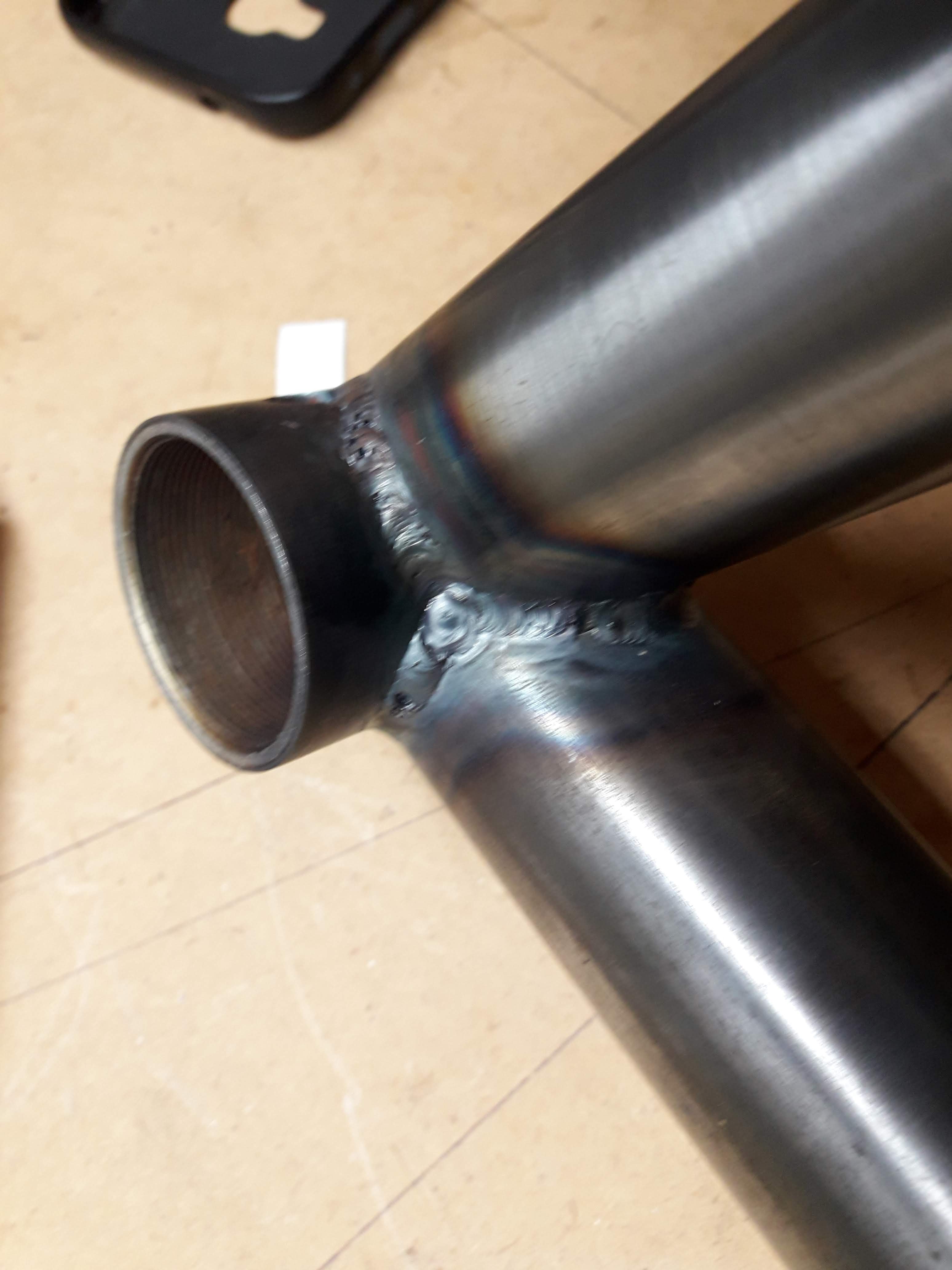
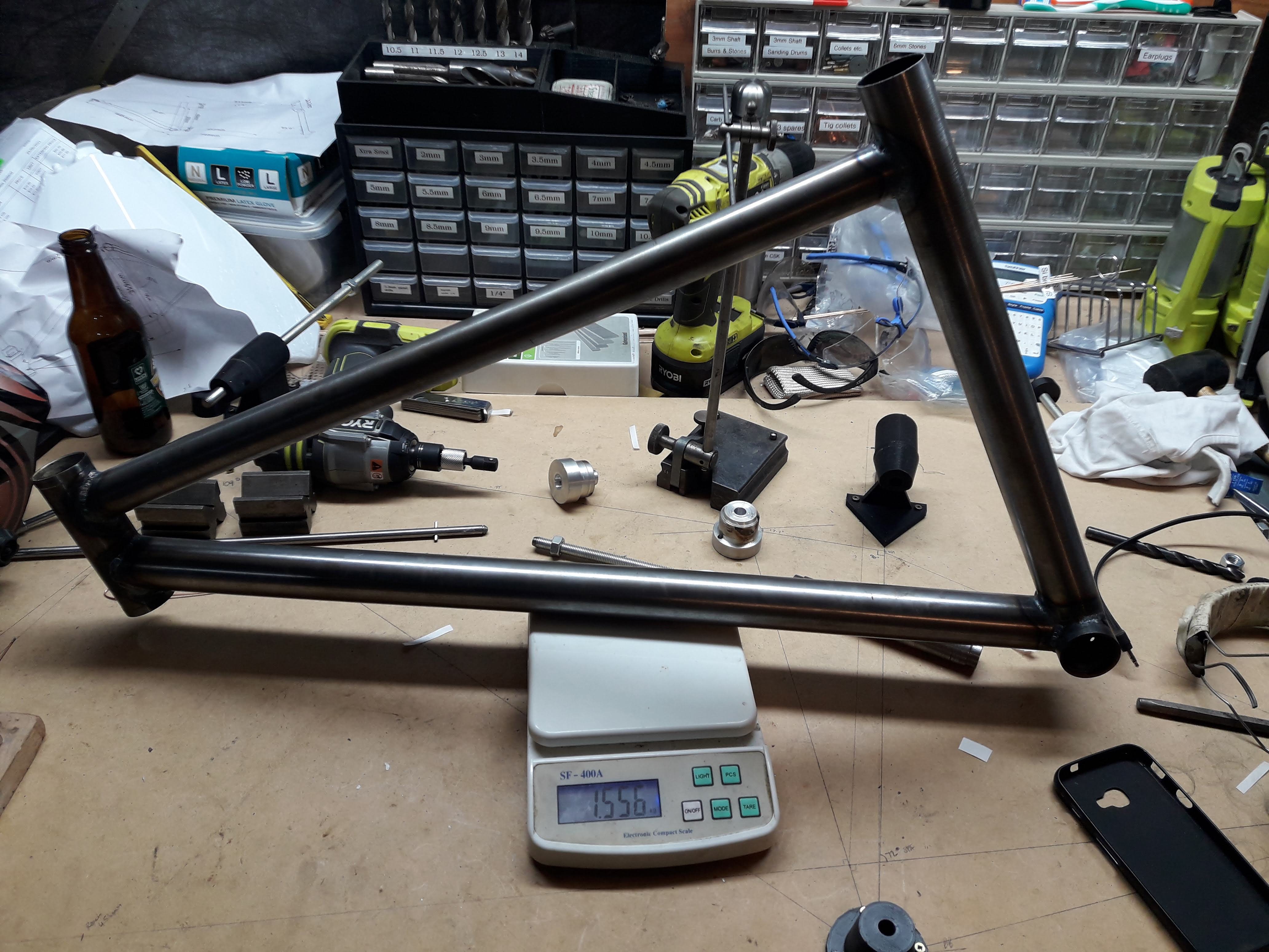
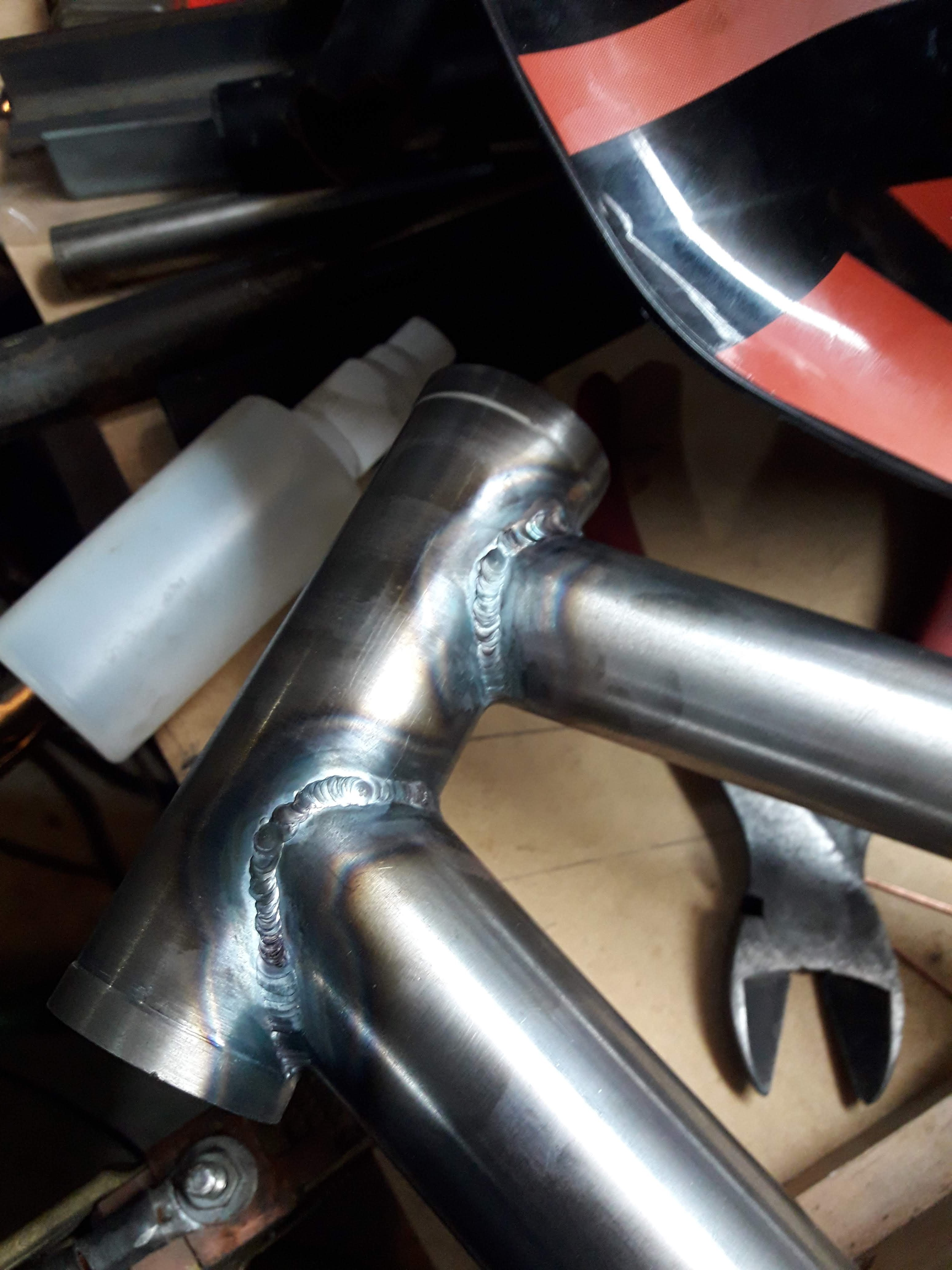
More pics of welds: These are the uglier ones: I think the one sied of the BB wasn't clean or still had paint residue in the steel cause it was a bit fizzy and I couldnt really do much about it. I popped it on the scales to see how things are tracking: 1556g, not too bad. I think it will come out around 2.7kg mark, I have been making the "dropouts" (thru axle so they dont drop anything out) and they are going to be a bit heavy hahaha. I turned a reducer out of stainless on the lathe, which took a long time because my lathe is very worn out. A heck of a lot better than no lathe though! In the frame: This actually added 10% to the weight of the frame so far haha. I don't really care about the final weight that much, but I think it is worth considering while I am making bits and pieces for the frame.
-
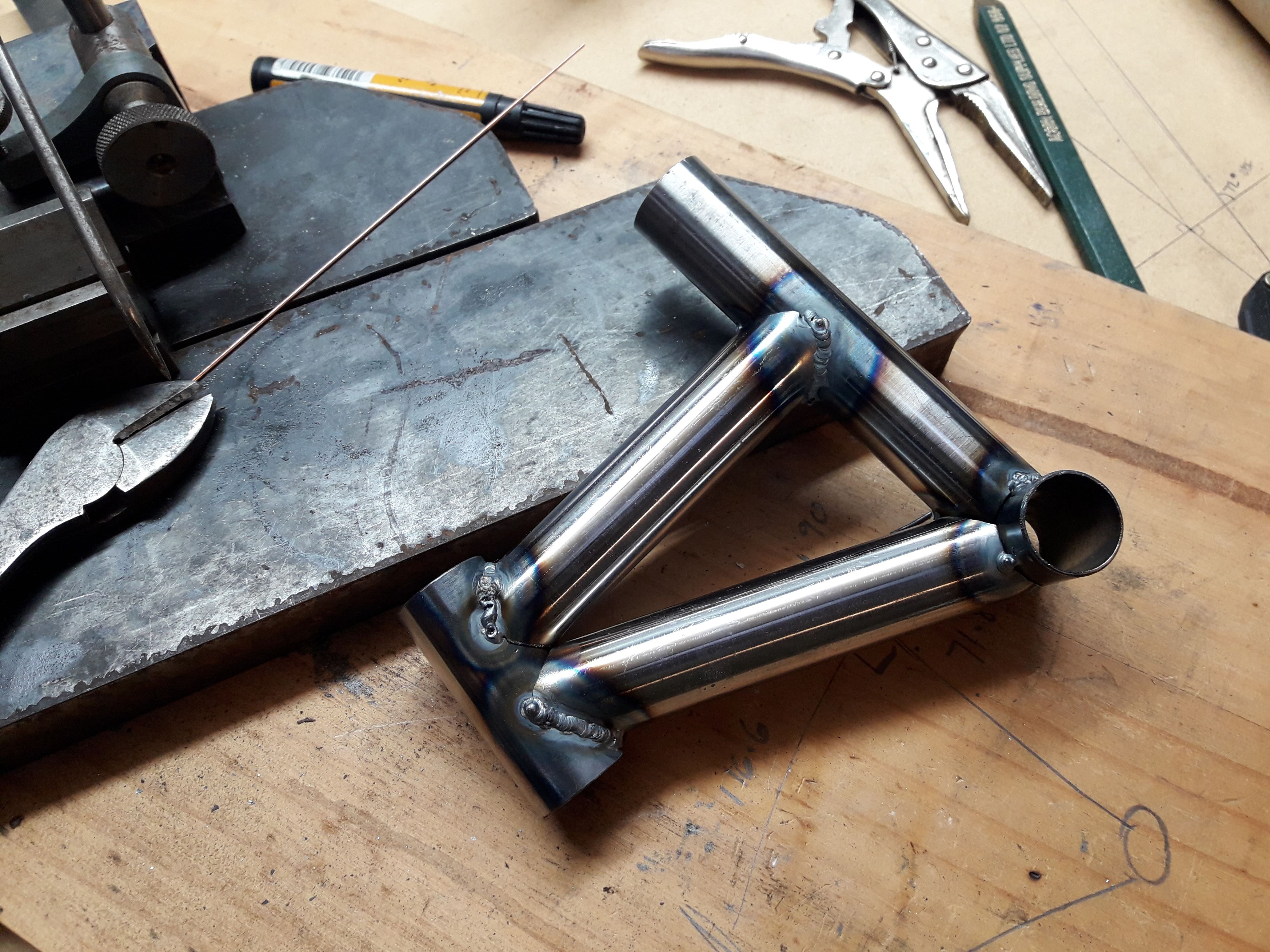
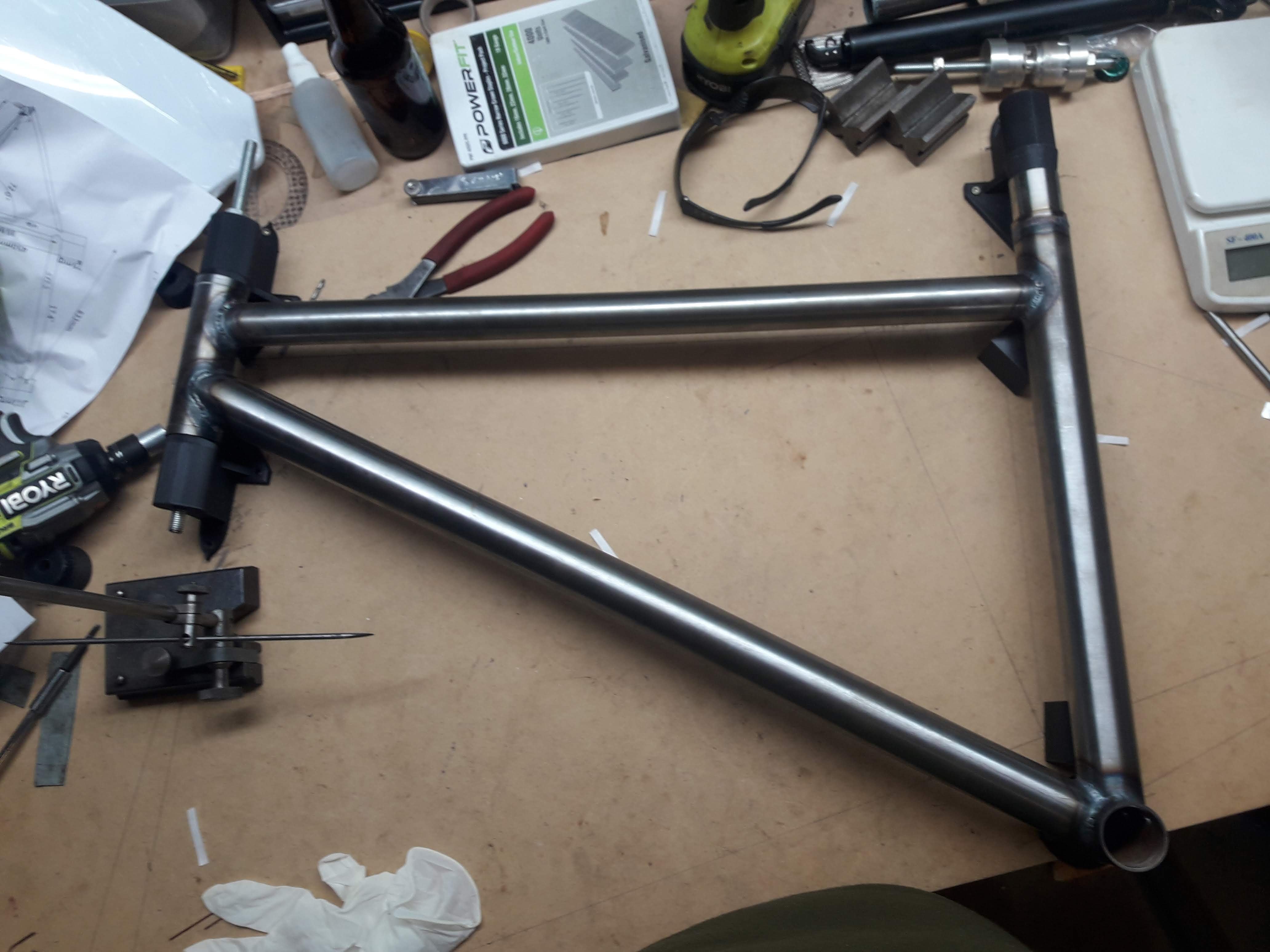
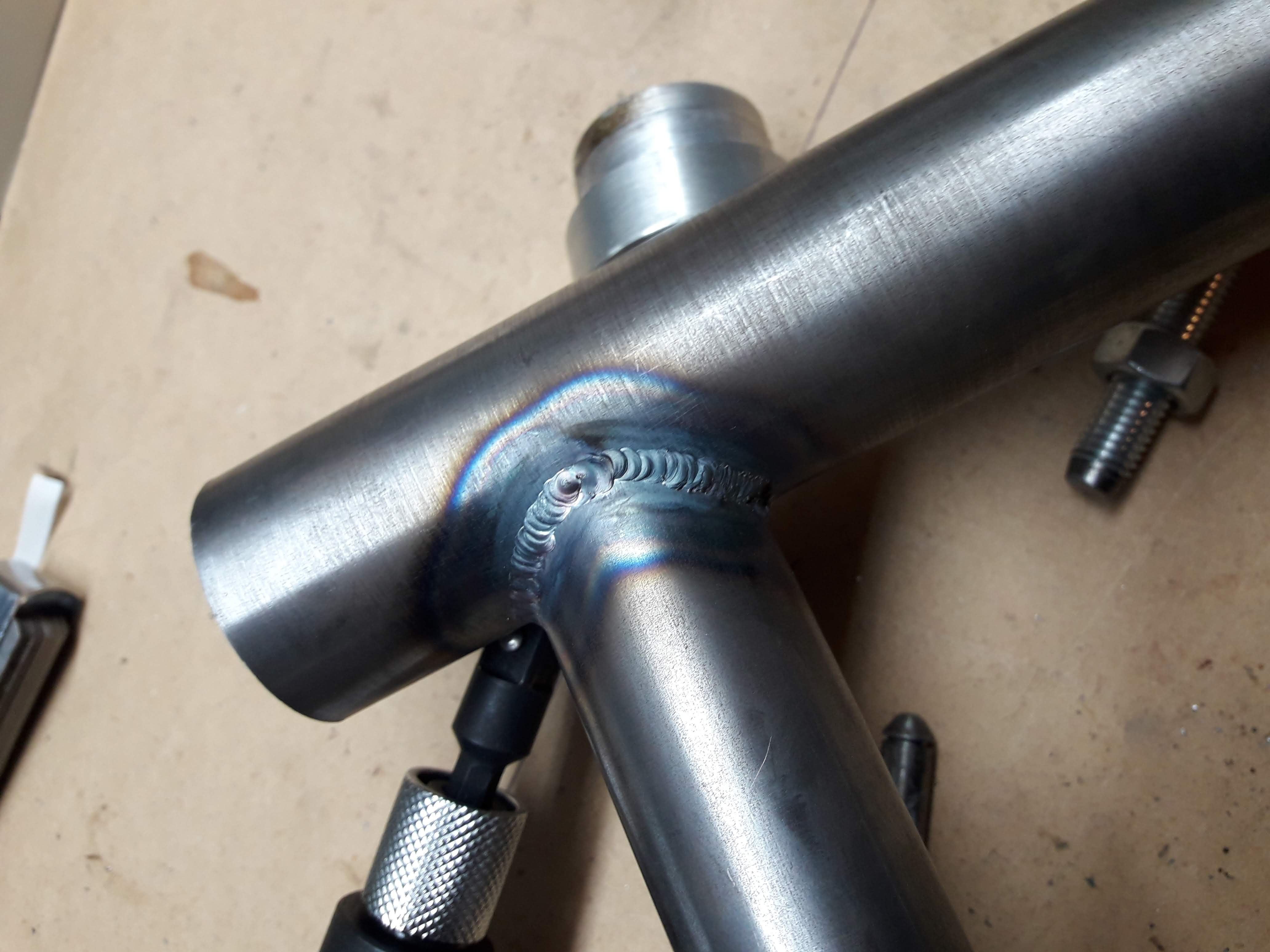
Front triangle is now fully welded, a few rough patches as you would expect for a noob but on the whole I am pretty happy and fairly confident that if will hold together fine I turned up some heatsinks out of scrap ali I had laying around to try minimise distortion: Some of the welds: The heatsinks probably helped, but the headtube has ovalised a bit. I will probably just give it a bit of a squeeze to get it close and see how it goes.
- 102 replies
-
- 12
-

-
Some shots of the fitup: And tacked it in place. Current toll on the jig: 2 plastic parts melted haha. though they did their job, and 1 is still useable. As a single use jig I still think its pretty good. Probably should have gotten a bunch more done today, but ended up getting carried away on my morning bike ride and did 20km/700m vert up Pirongia mtb trails and was pretty tired after that!
- 102 replies
-
- 17
-
-
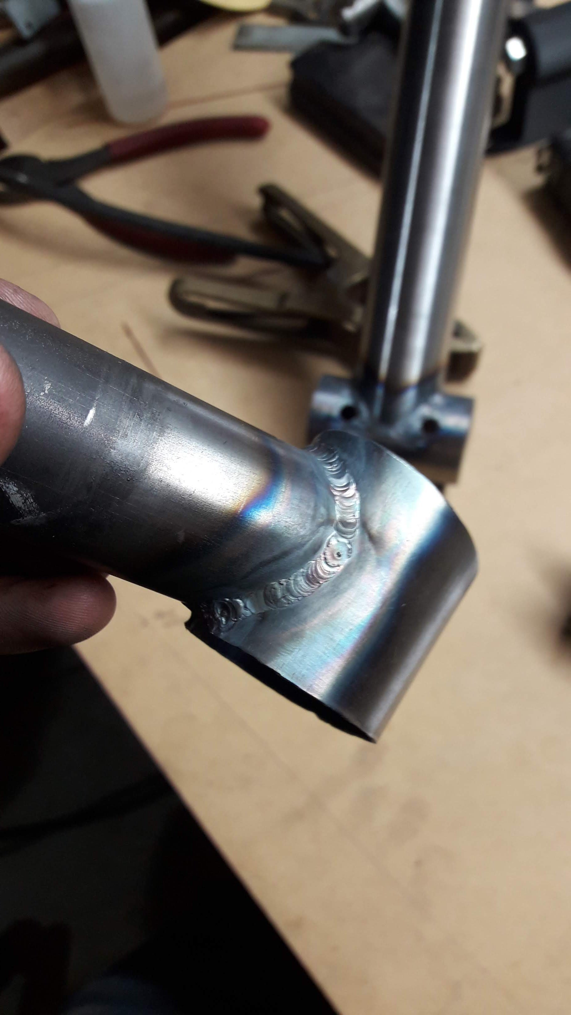
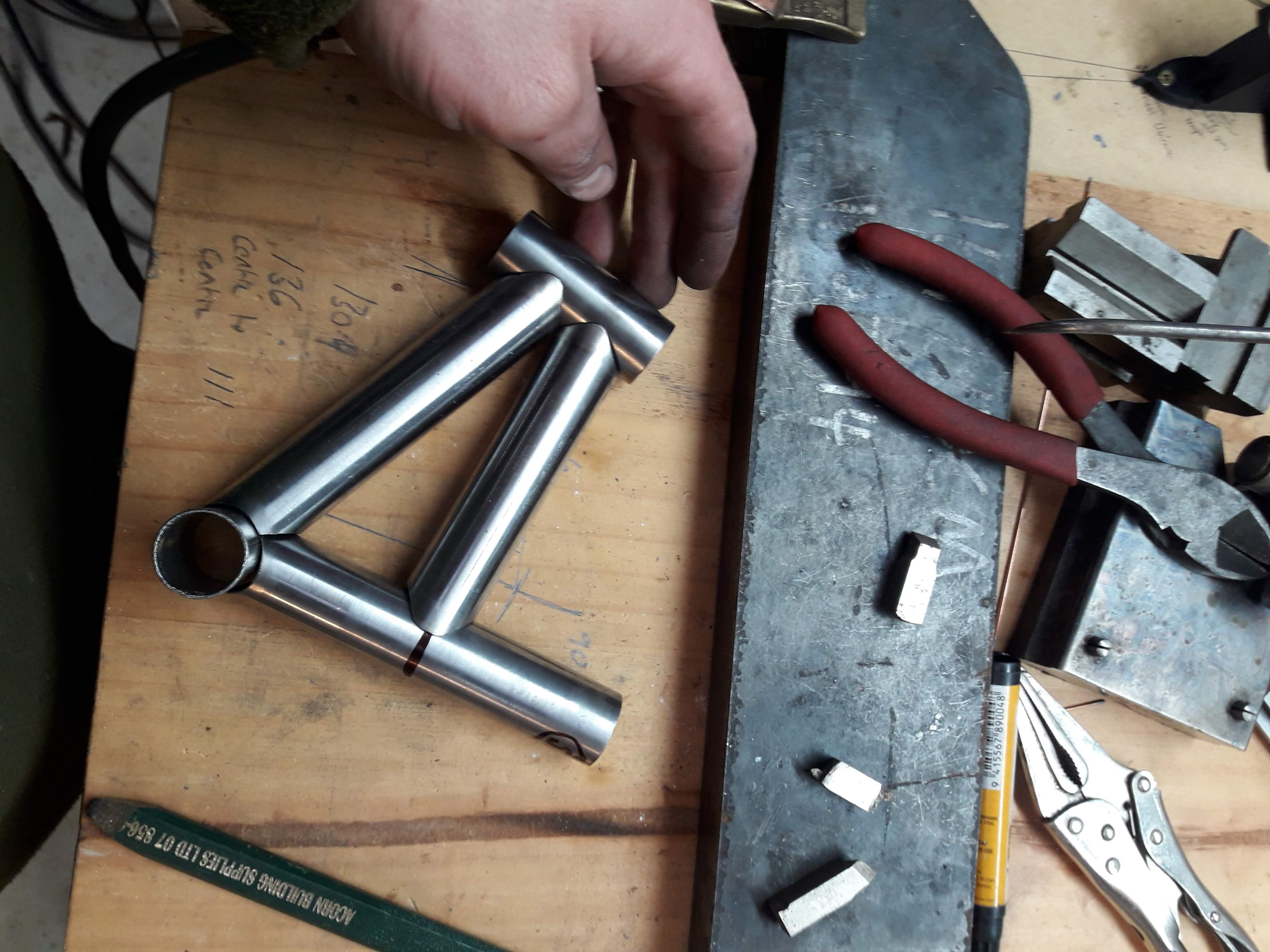
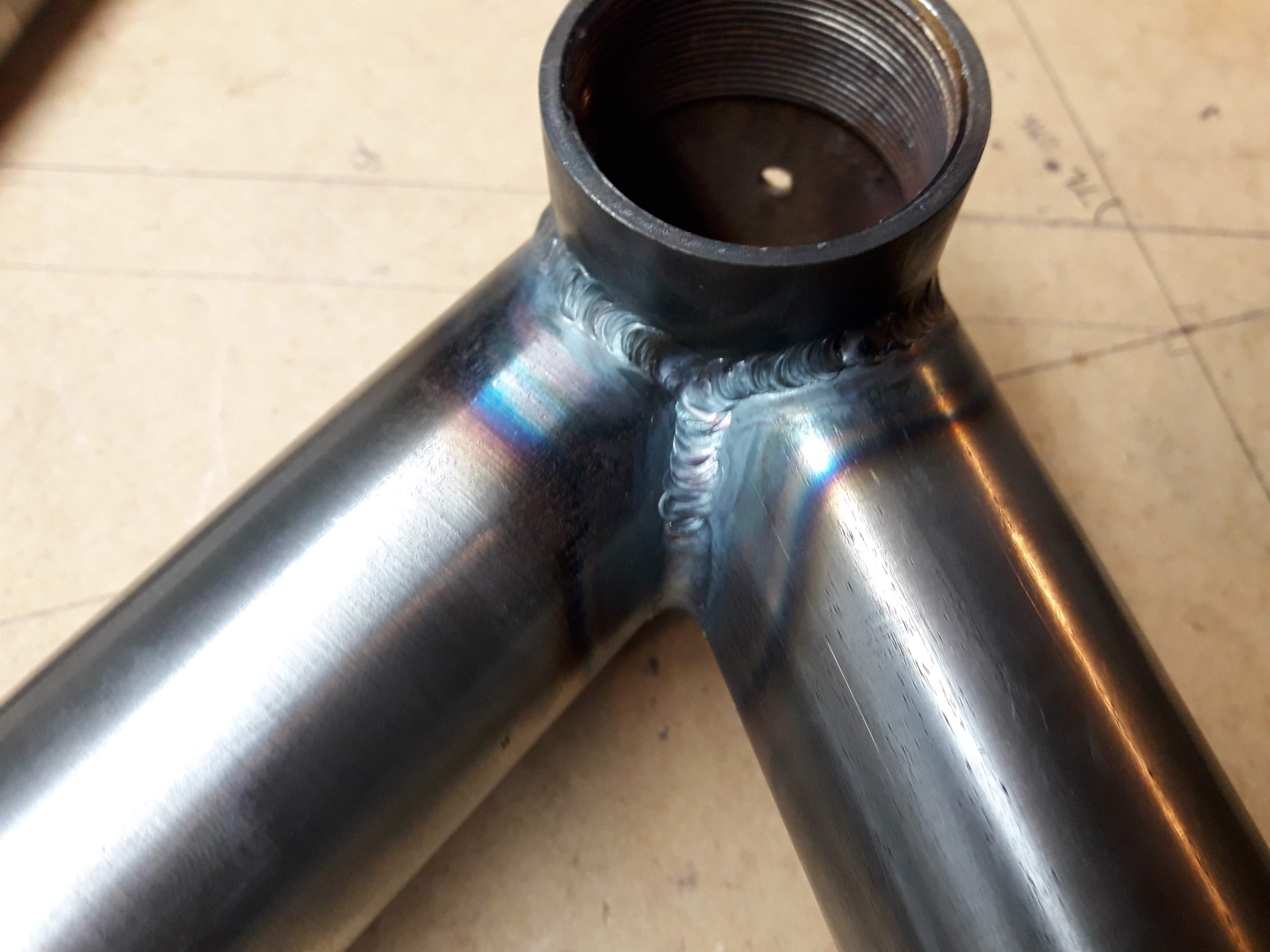
I had heard about the brake cleaner thing, pretty scary really. I figured out most of my problems with getting nice welds had more to do with sheilding. I'm pretty sure my torch body in just old and worn out. It has a gas tap on it that didn't have an o ring so I put one in, the wrapped it with electrical tape. I have borrowed a gas lens off a friend and that seems to help too and has brought down my gas flow requirement which is nice. I have a new torch body and gas lens setup on the way from aliexpress. After coping some of the tubes I had a couple of offcuts left so I had a little test on those with the gas lens setup: Happy with that. By this time I had already tacked the seat tube to the BB, so I just went ahead and welded that up. you can see it in the background of the above picture kind of, its not quite as good as my test weld as its a bit tricky with the BB being 3mm and the tube 0.9mm trying to get the heat to go where you want it. Heres a few shots of the tubes getting added to the jig: On the picture below you can see a little block that I 3d printed to get a level surface to reference so I could accurately clock the tube 90 degrees for the bottom bracket cope, also fresh deliverys from @ThePog thanks!: A few more pics to come in the next post...
-
That is awesome! I will have to make one of those once I have finished on this bike
-
PM'd about the lengths. Good to know that quality will do the job! I figured with the remaining tube I have I would make a tiny bike. So made a 1:5 scale version of the frame hahaha Started welding it together and had all of the contamination problems. I have been cleaning the metal with alcohol, I think it might not be aggressive enough so I figured I would call it quits for the day and try again later with some acetone. I have probably hit my learning absorption limit for the day as well. go to sleep and try again tomorrow.
-
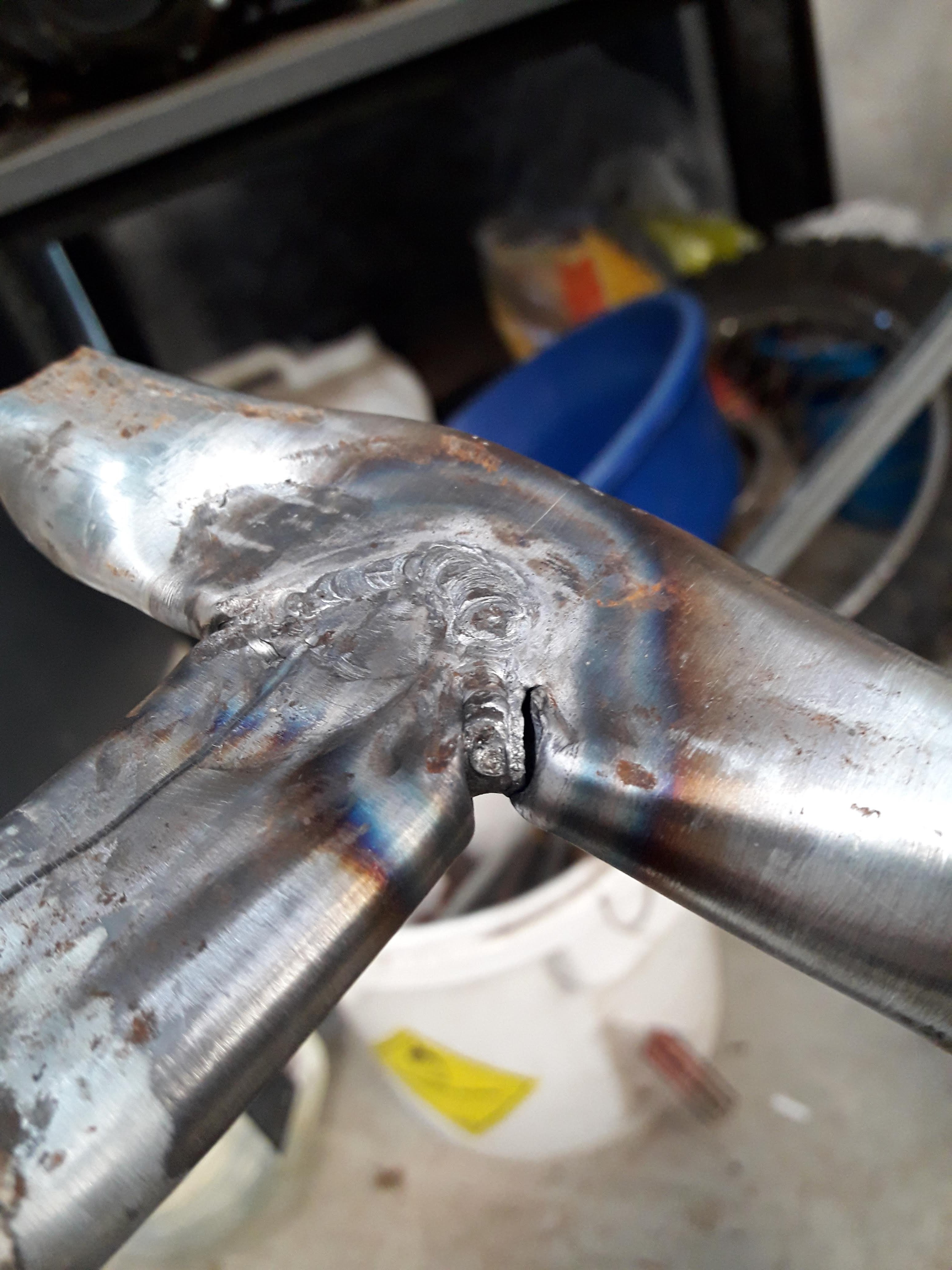
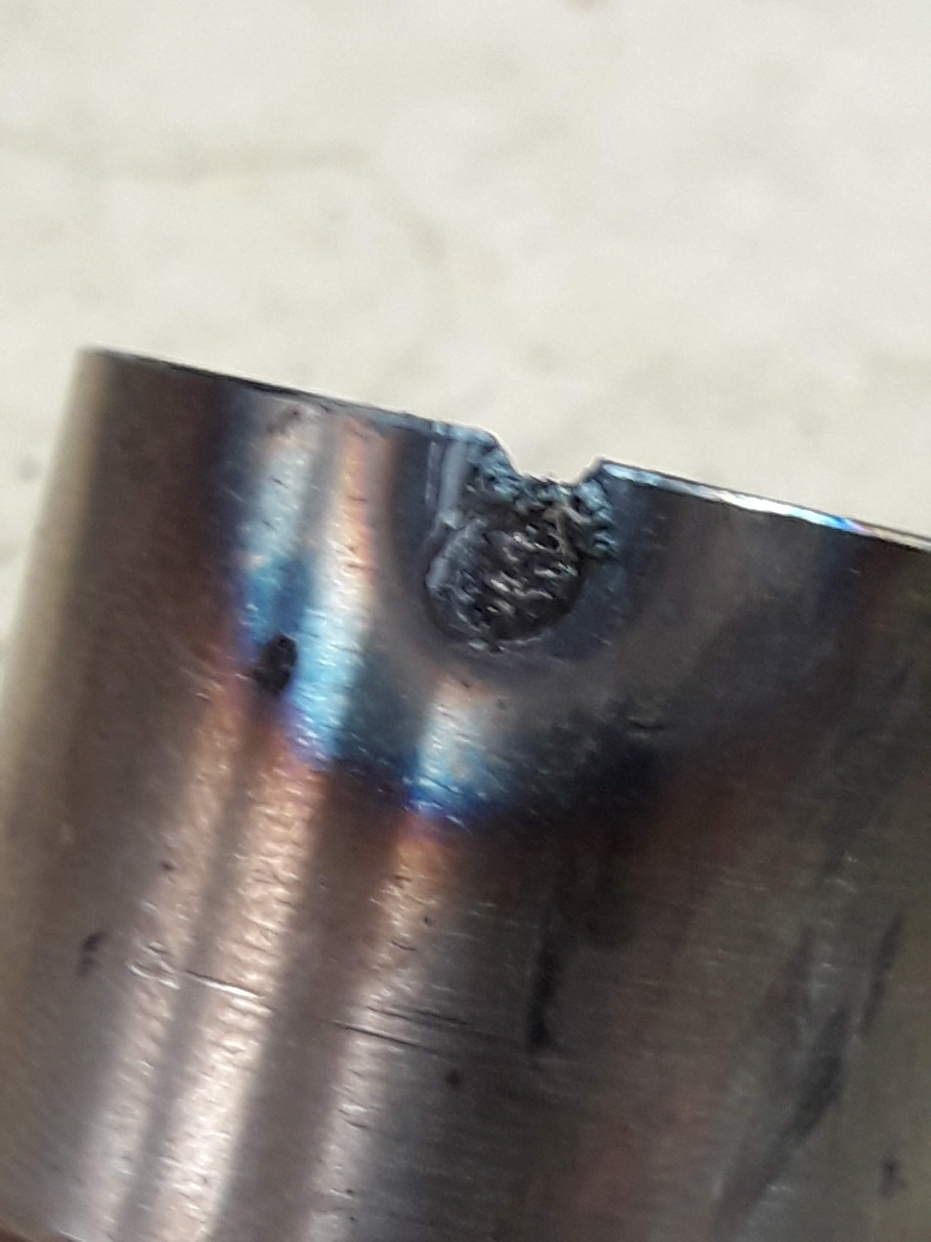
Here is the failed weld: While it certainly isnt going to win any beauty contests I think as a bike frame component that weld wouldn't fail, it took a lot of beating on to get it to crack. I coped and welded a few more joints and that's where I am up to now, I think there must be pockets of galve causing issues with the weld as I am getting little pockets of contamination even though everything looks nice and clean: ' I am probably going to do a few more practice copes and welds and then just go for it. I figure this is bike frame no.1, may as well just get it done and consider it to be a learning process and not a final product.
-
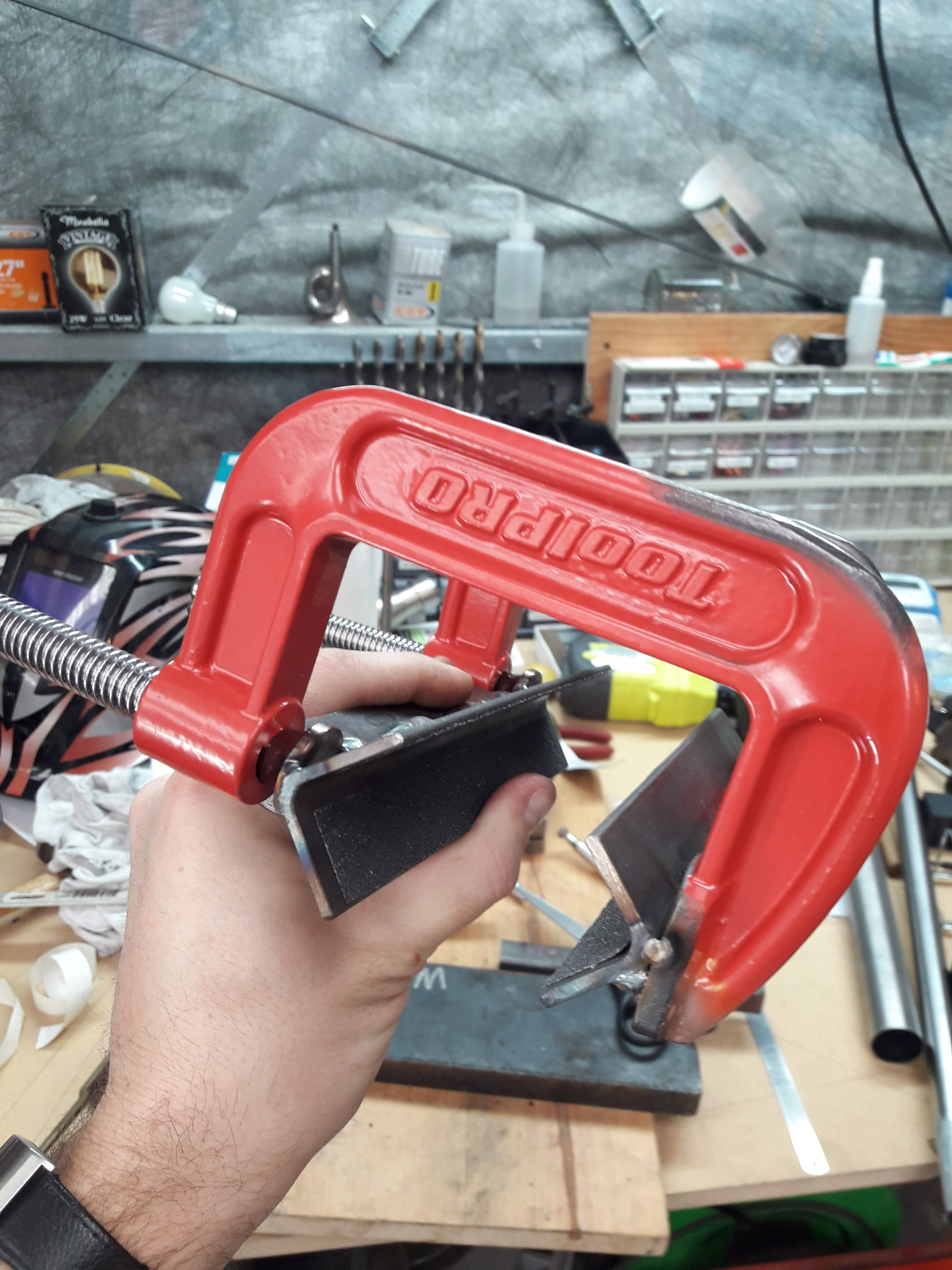
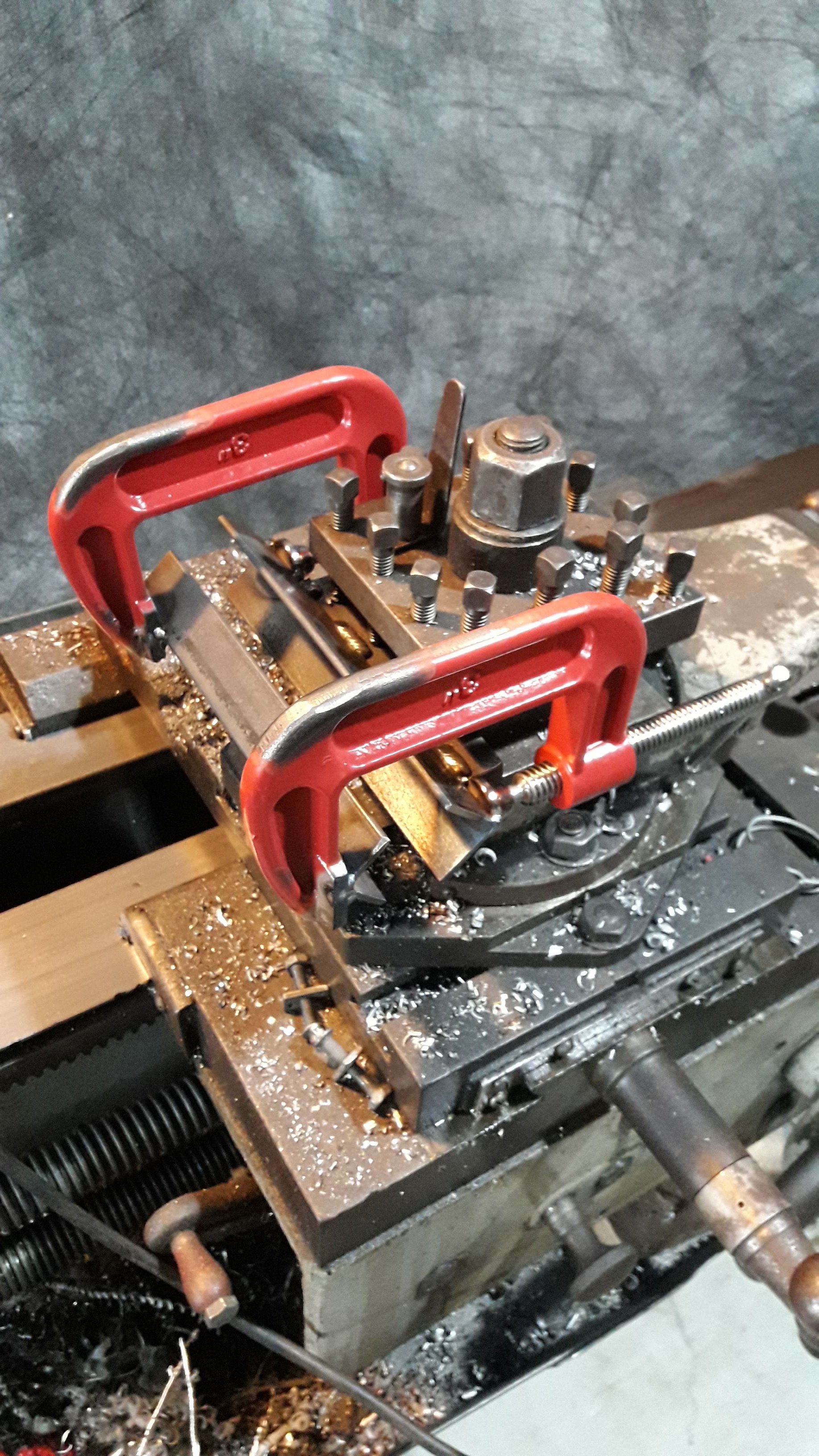
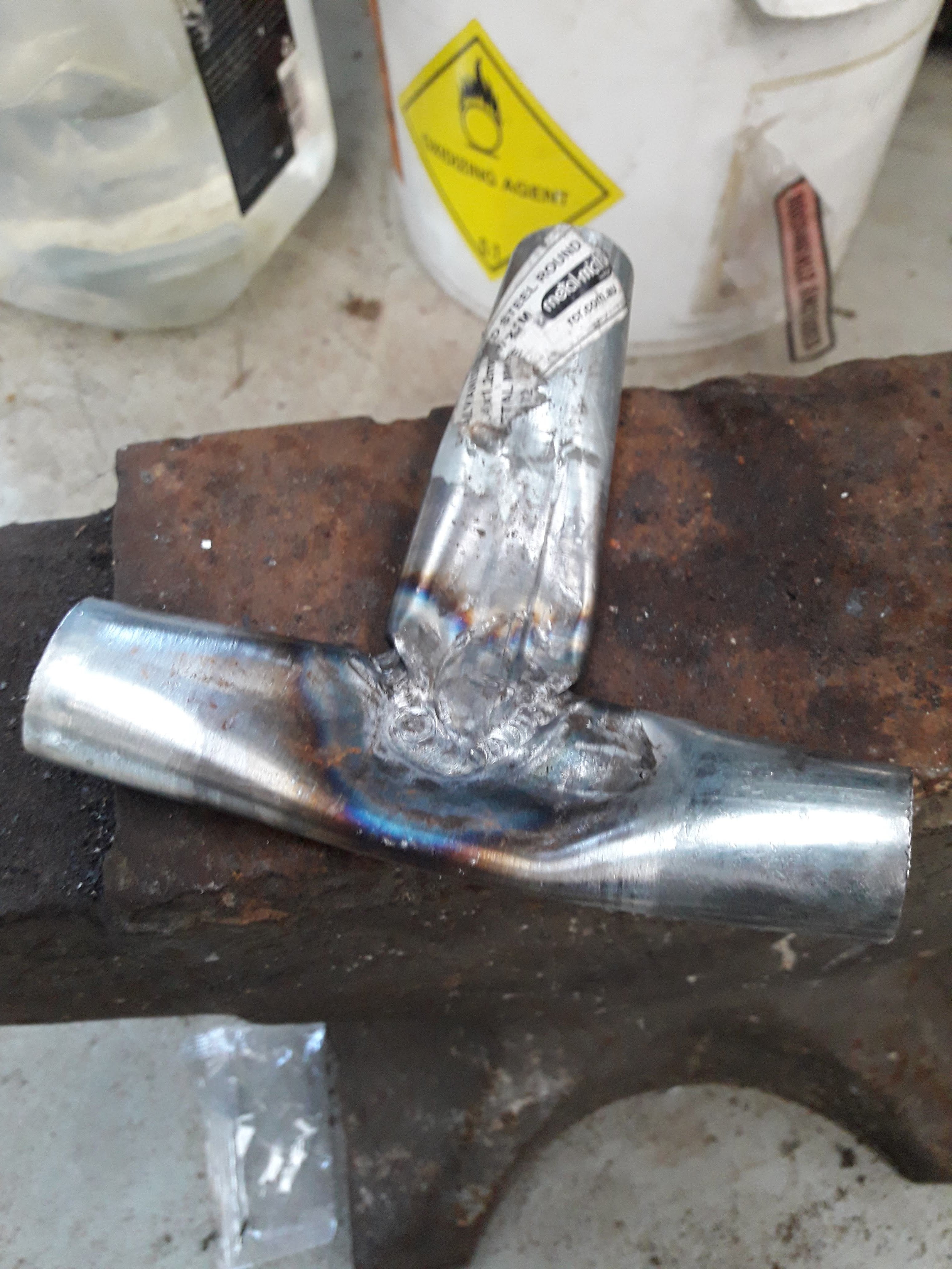
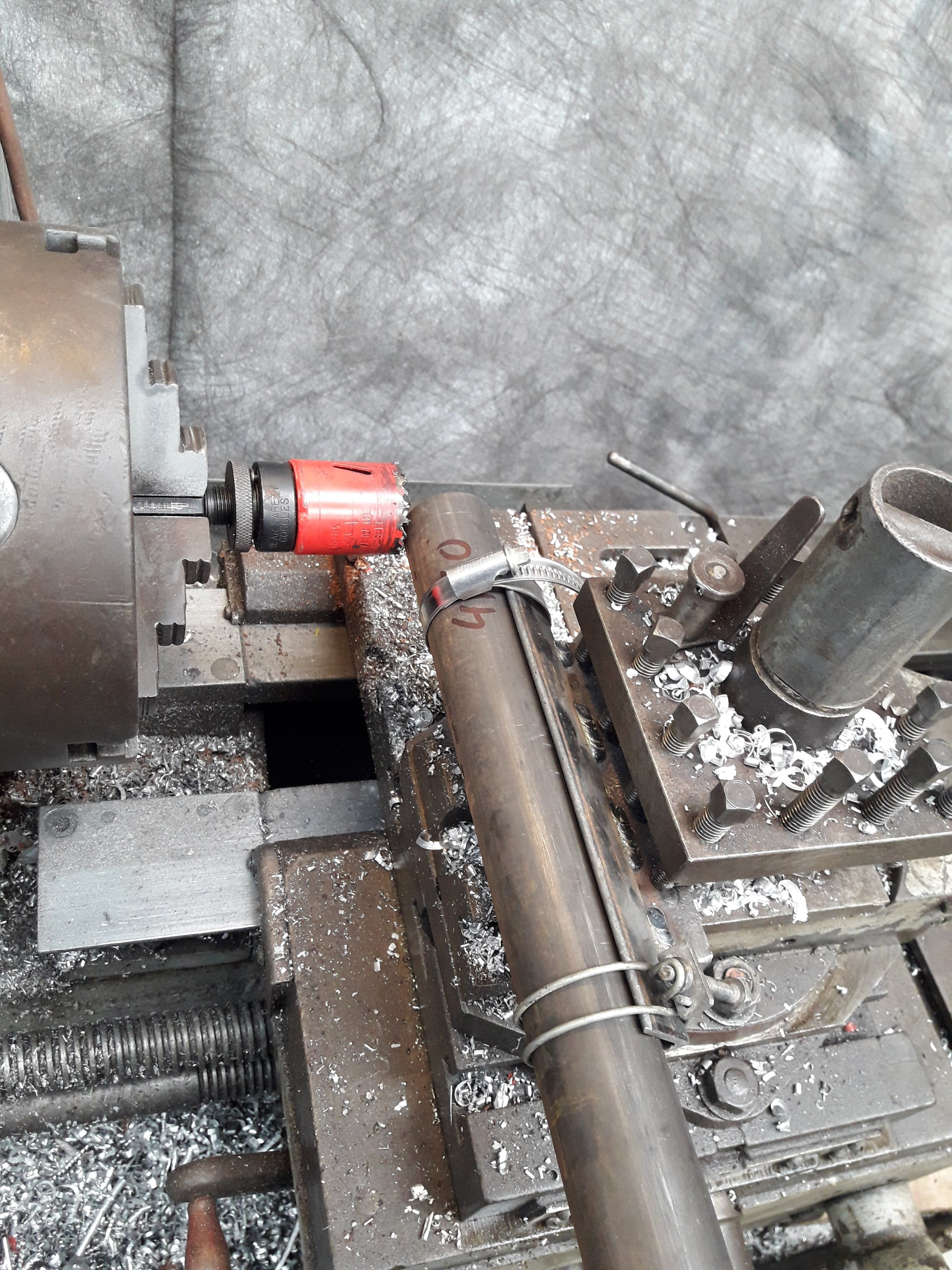
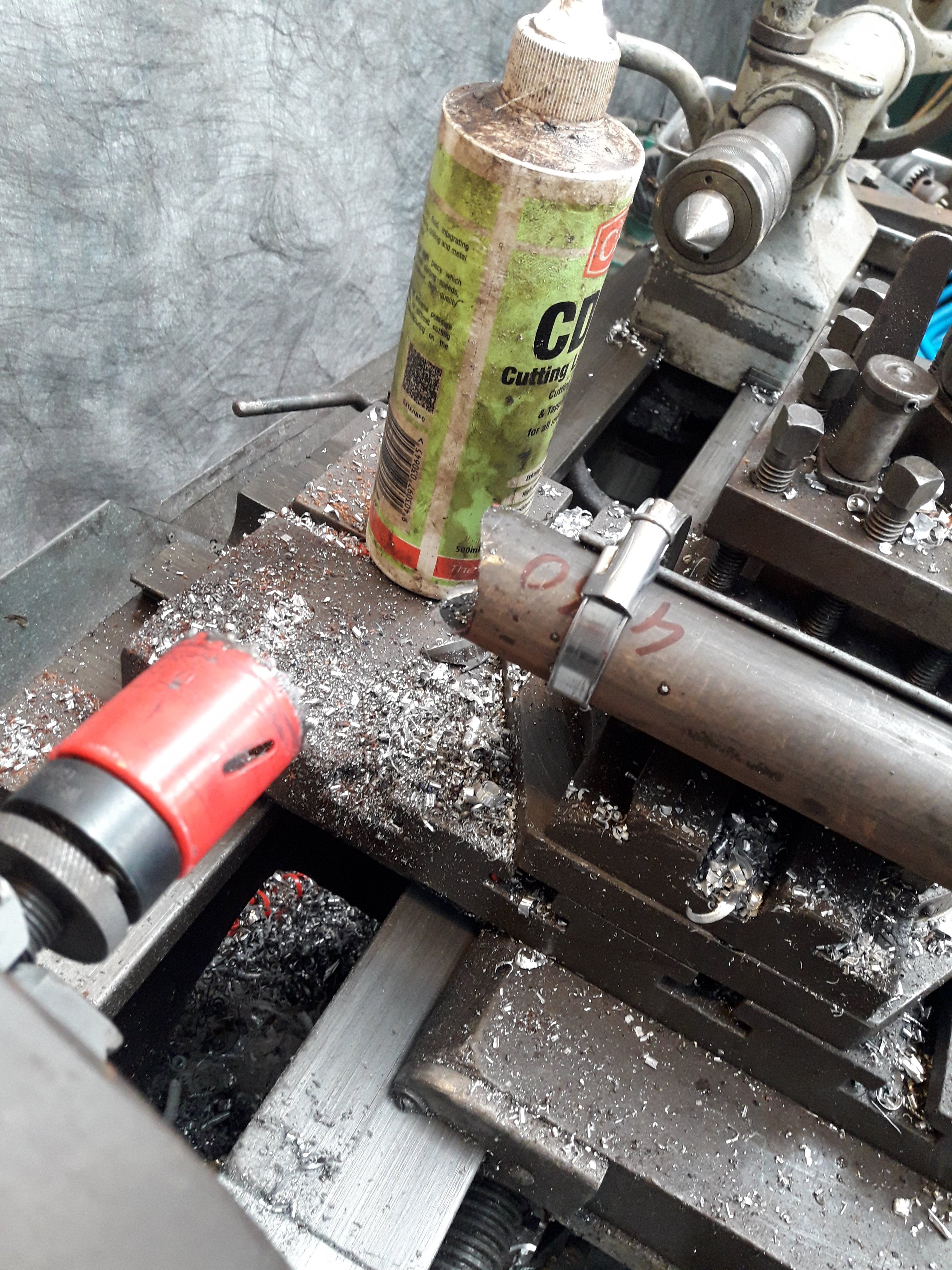
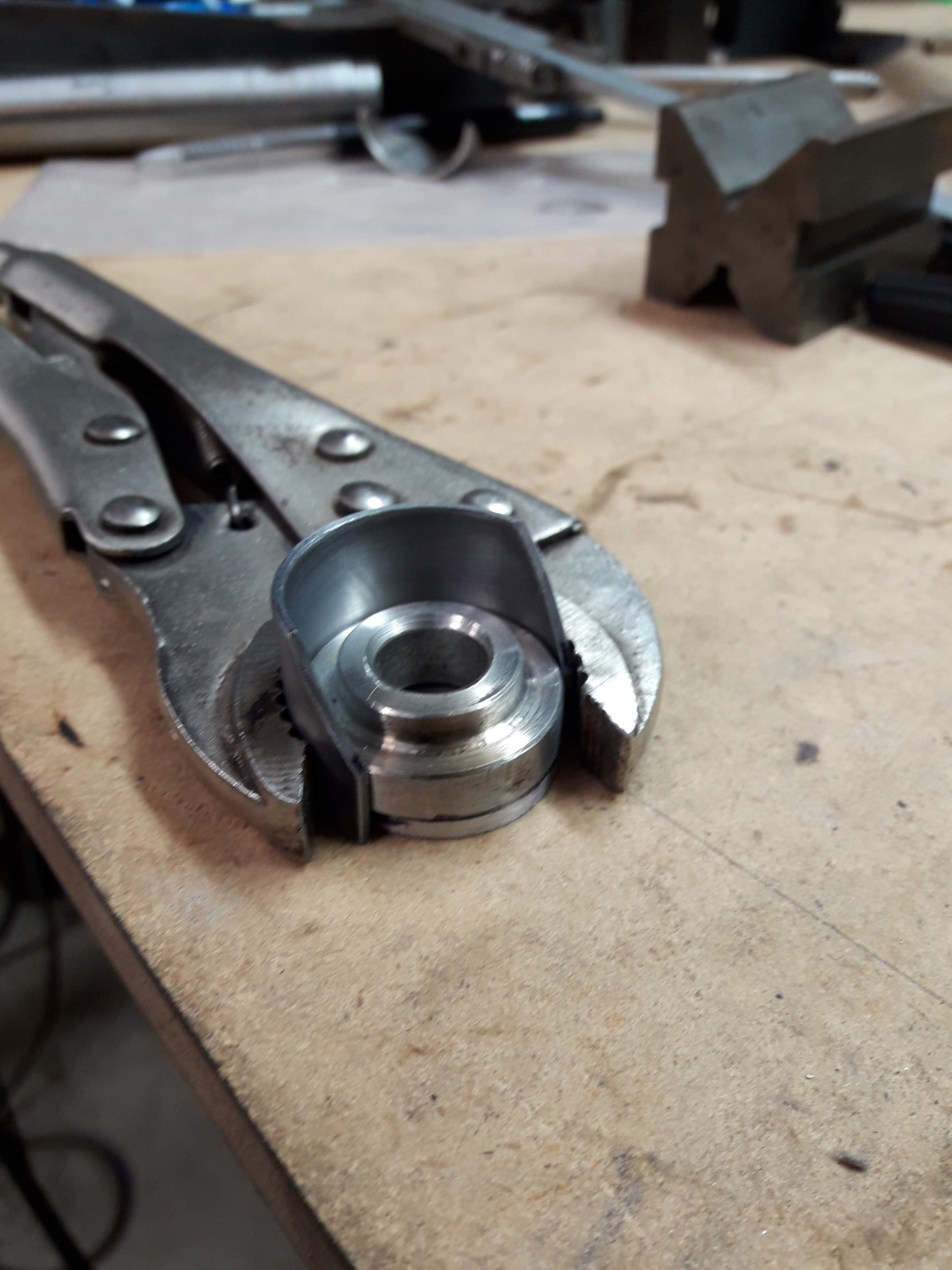
Progress update: No further work on the frame But a lot has been happening working towards the frame build. I turned up an arbor for a 1" holesaw and welded the holesaw to the arbor as @Valiant suggested and got some 1" mild steel tube 1.2mm thick to practice welding on. It is galve which is somewhat annoying, so I ended up plugging the end and filling it with acetic acid to clean all the galve off the inside. I filed and sanded the galve off the outside, though I think there may still be tiny specs or pockets of galve hiding in the dips and divots of the surface as I am having a bit of difficulty with porosity occasionally in the weld. I also upgraded my coping jig as the hose clamps just weren't cutting the mustard. A couple of g clamps welded to a second piece of angle iron now clamp the tube: I lined the jaws in skateboard grip tape for maximum traction as if the tube slips it snaps the teeth off the holesaw which is super annoying. It works great. I might chop off the t bars and turn some thumb screws with a nut on the back to make it quicker to open and close when its mounted on the lathe later, but for now its good to go. This is my first practice piece: I thought burning through was going to be much more of an issue but it was not a problem. I found around 55a seemed to work best, the difficulty is getting comfortable and moving the torch in an arc so you don't end up balling your filler before you get to dip it in the puddle. I took that join over to the anvil and squashed it flat, it held together well: So I whacked it backwards and forwards until it failed. It took a lot, more than what I was expecting considering it wasn't a very pretty weld!
-
food for thought...
-
I did wonder about tig brazing. I did a bit of googling and found a bunch of people who said it cant be done blah blah blah, but I found the same thing when I googled about mig welding a bike frame. Then there was one thread where a dude actually did it and it was fine. He even posted up a update a few years later and said it was still all good, no cracks or failures. It was a trials frame too so not something that would not have been nana'd either Edit: just had a look, er70s-2 is the recommended filler for 4130, its rated 483mpa tensile, the silicon bronze is 340mpa. Does that mean if the fillet is say 20% larger strength would be same same? Maybe we should make a few test pieces and smack em around with a hammer...
-
Oh yeah, I forgot to mention that. The jig parts are 3d printed. Means I can sit by the fire inside while I "make" a thing in the shed hahaha. I am thinking it will probably be a single use jig, we will have to see how they come out after the frame has been in and out a few times.
-
I have a tig, though I have a few hurdles to get over with it before getting on to welding the frame. First of all I am not very good at it, so practice is needed. Second, I don't have a pedal, a pulse function or downslope on my welder. I think if I can get a pedal sorted it will do the trick, it can take one but it is a very old cigweld with a 7 pin connector and I have not been able to find a pinout for it.
-
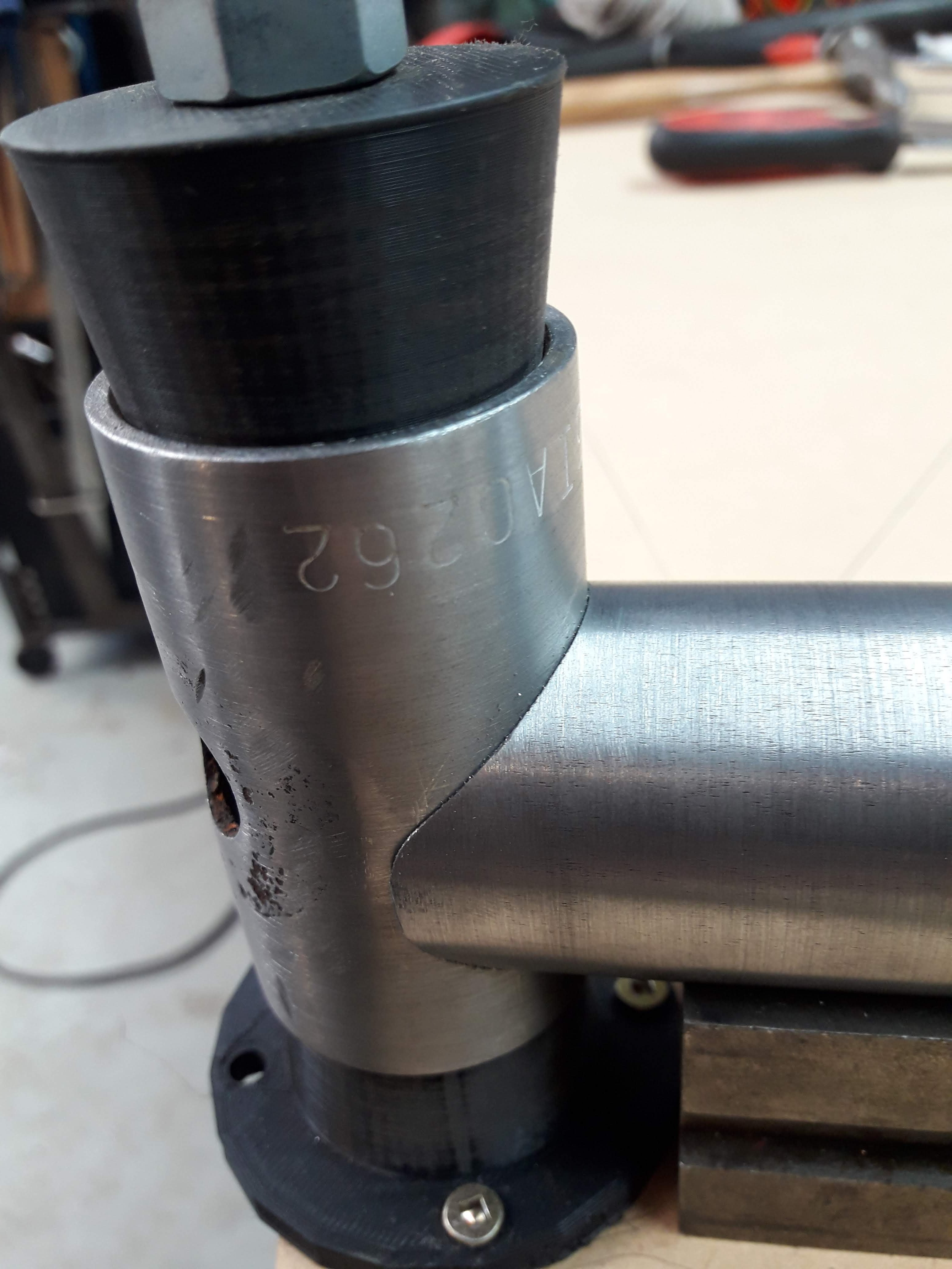
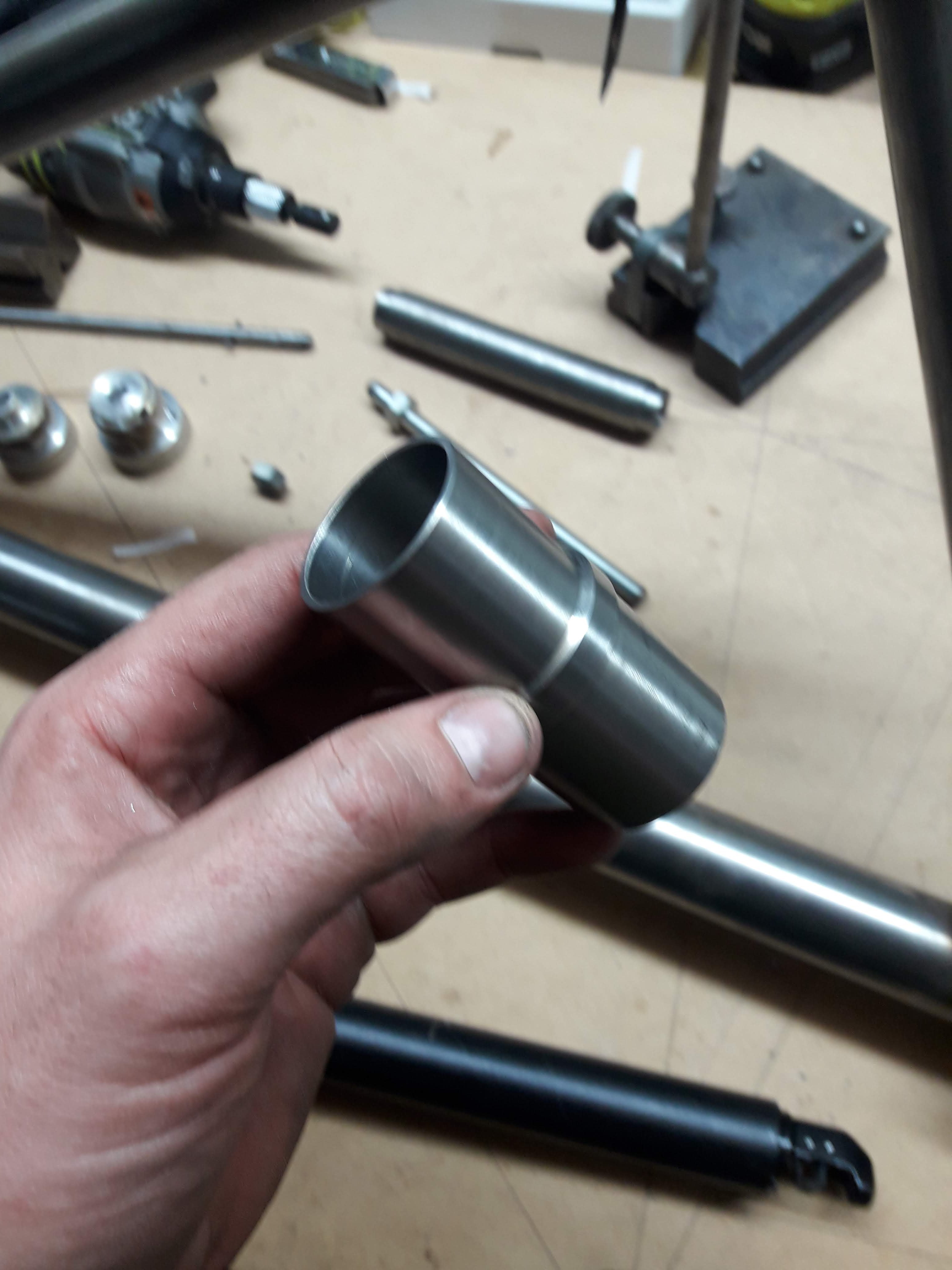
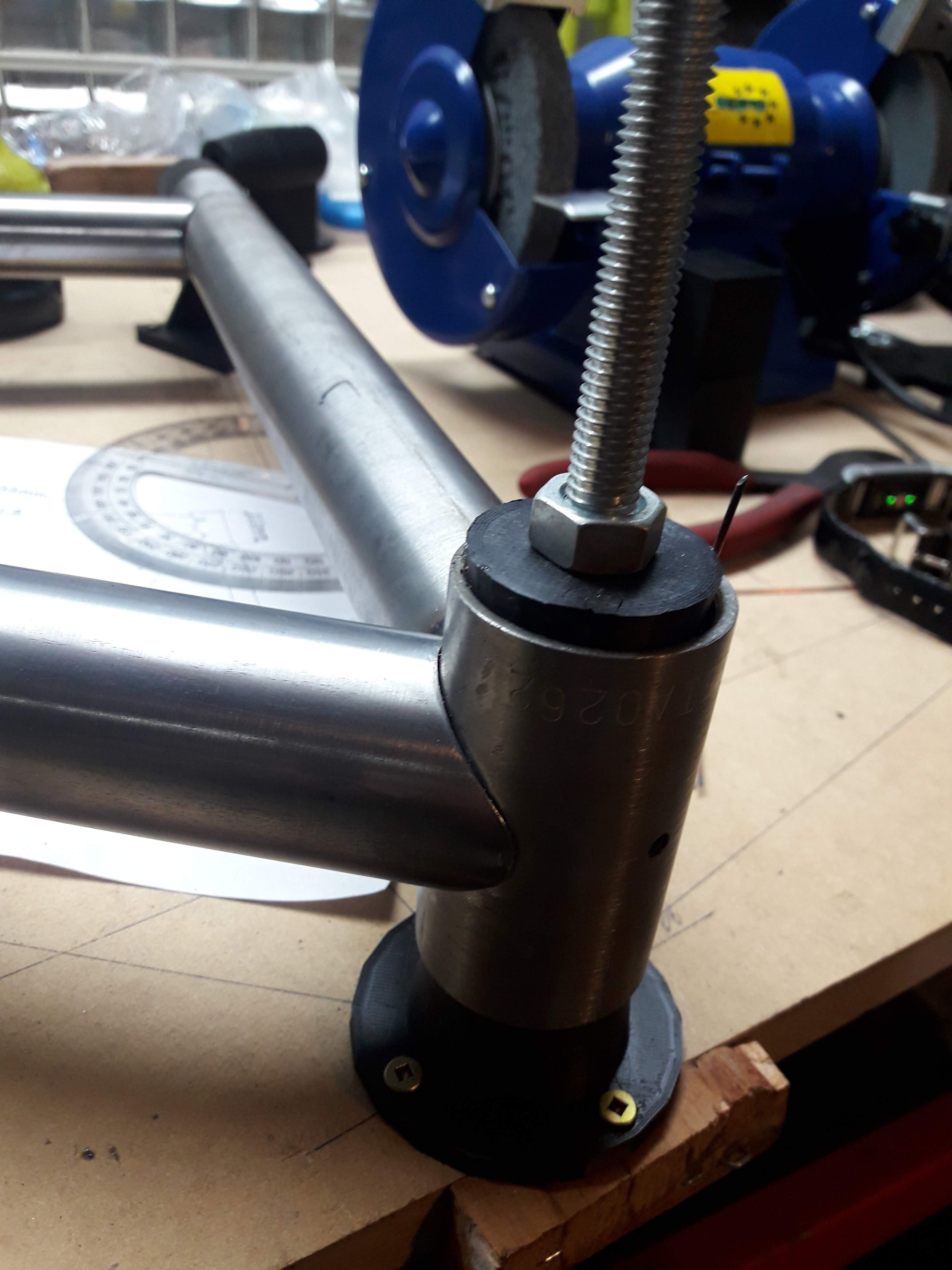
Spun up the tube with some sandpaper on the lathe, it is mildly terrifying contemplating what would happen if it comes flying out and stabbed you in the hand or something. I guess not being complacent is good! popped it in the jig and found I need to make an adjustment to my end piece as the cone is slightly too small for the ID of this tube. Spent a bit of time filing the coping to try get a nice tight fit. And thats about where I am up to at the moment. I need to practice Tig welding on thinwall on tube before I can get much further so I have ordered the recommended tungstens and consumables for my torch. Might have to get a lesson or 2 from @Geophy hahaha
-
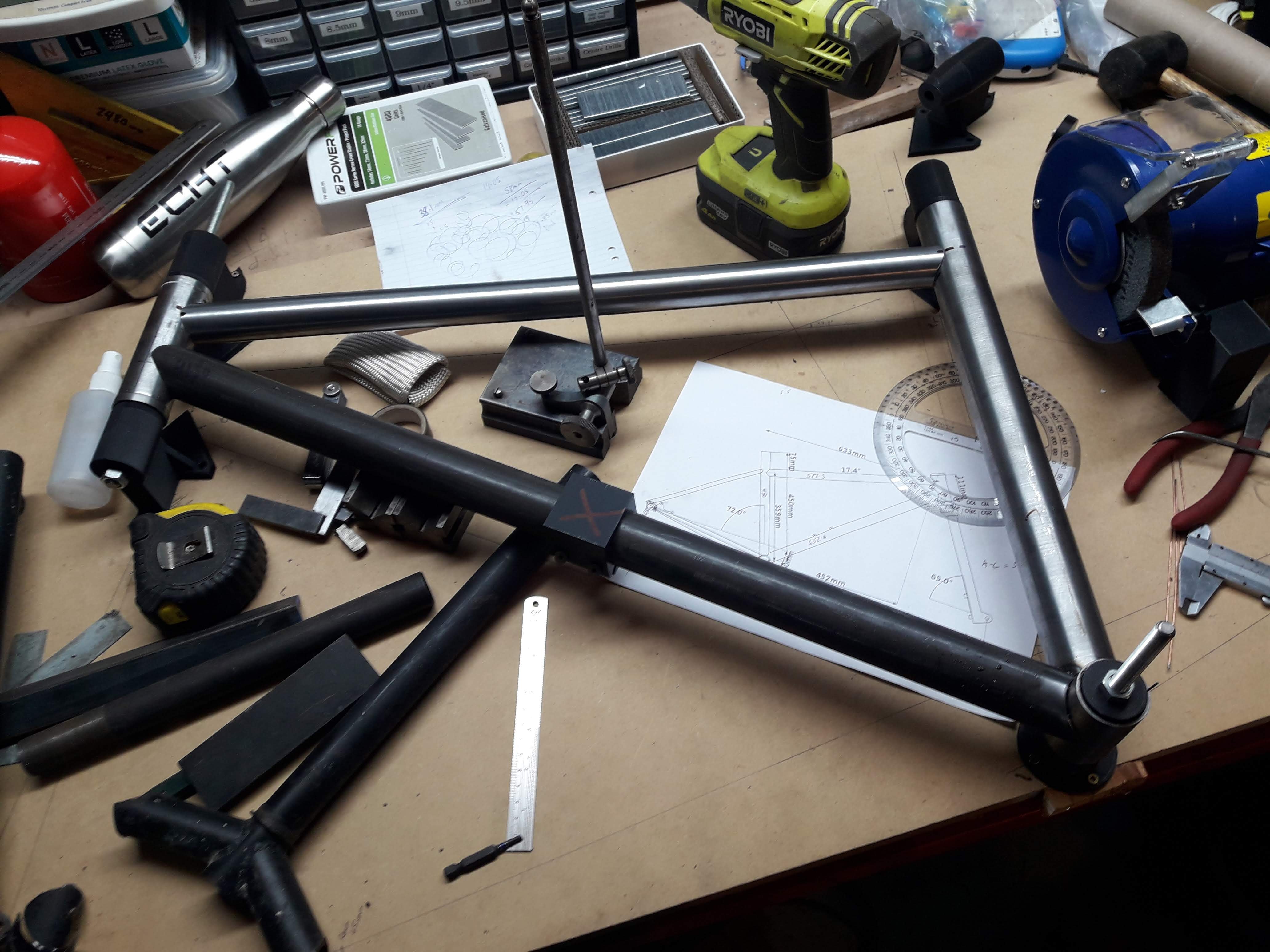
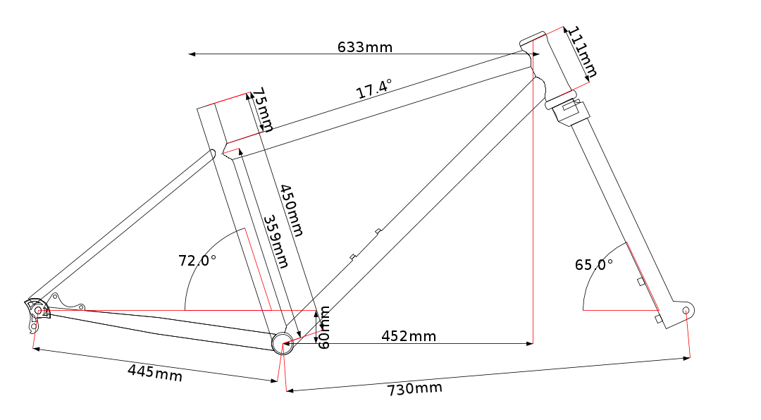
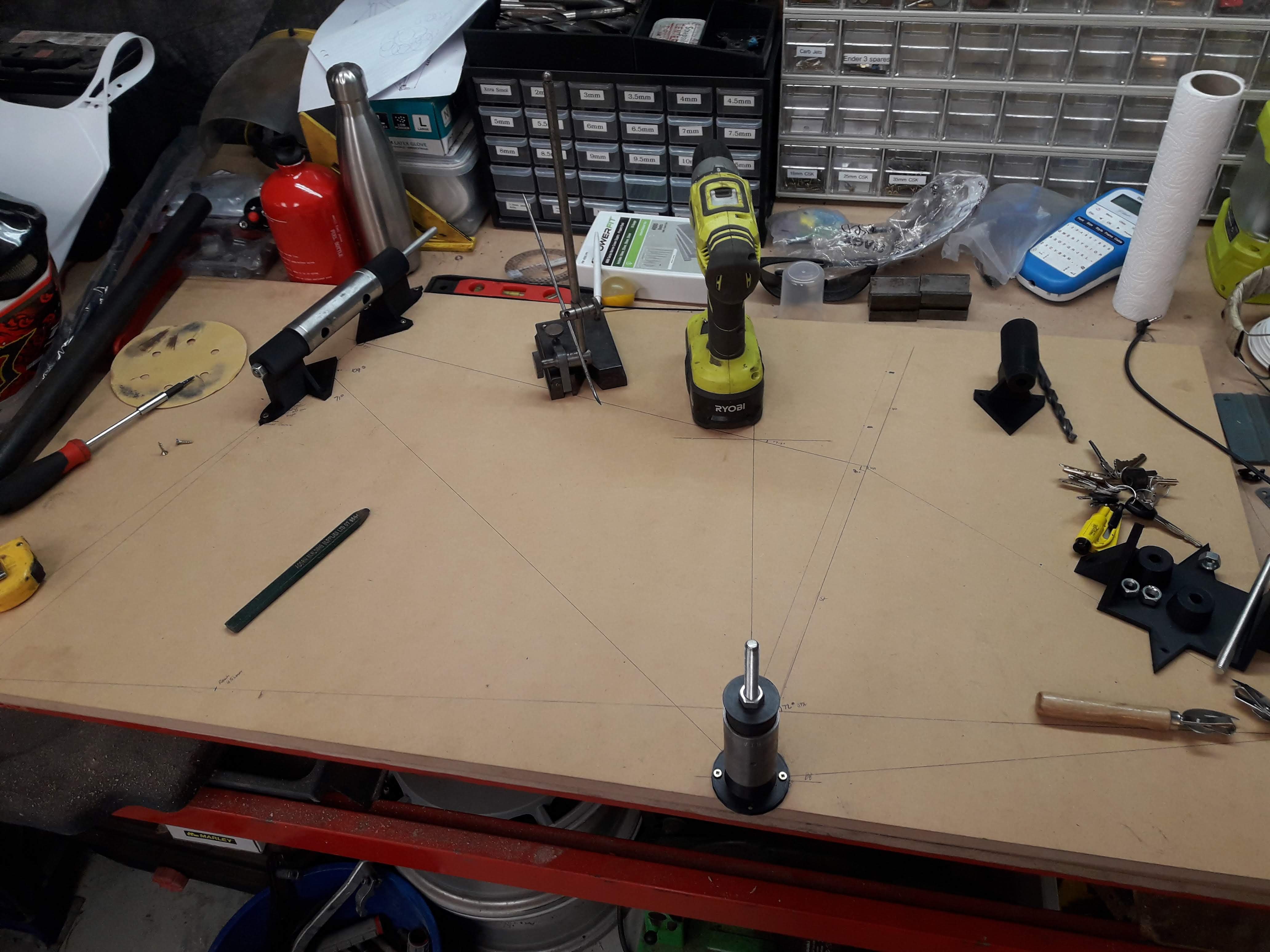
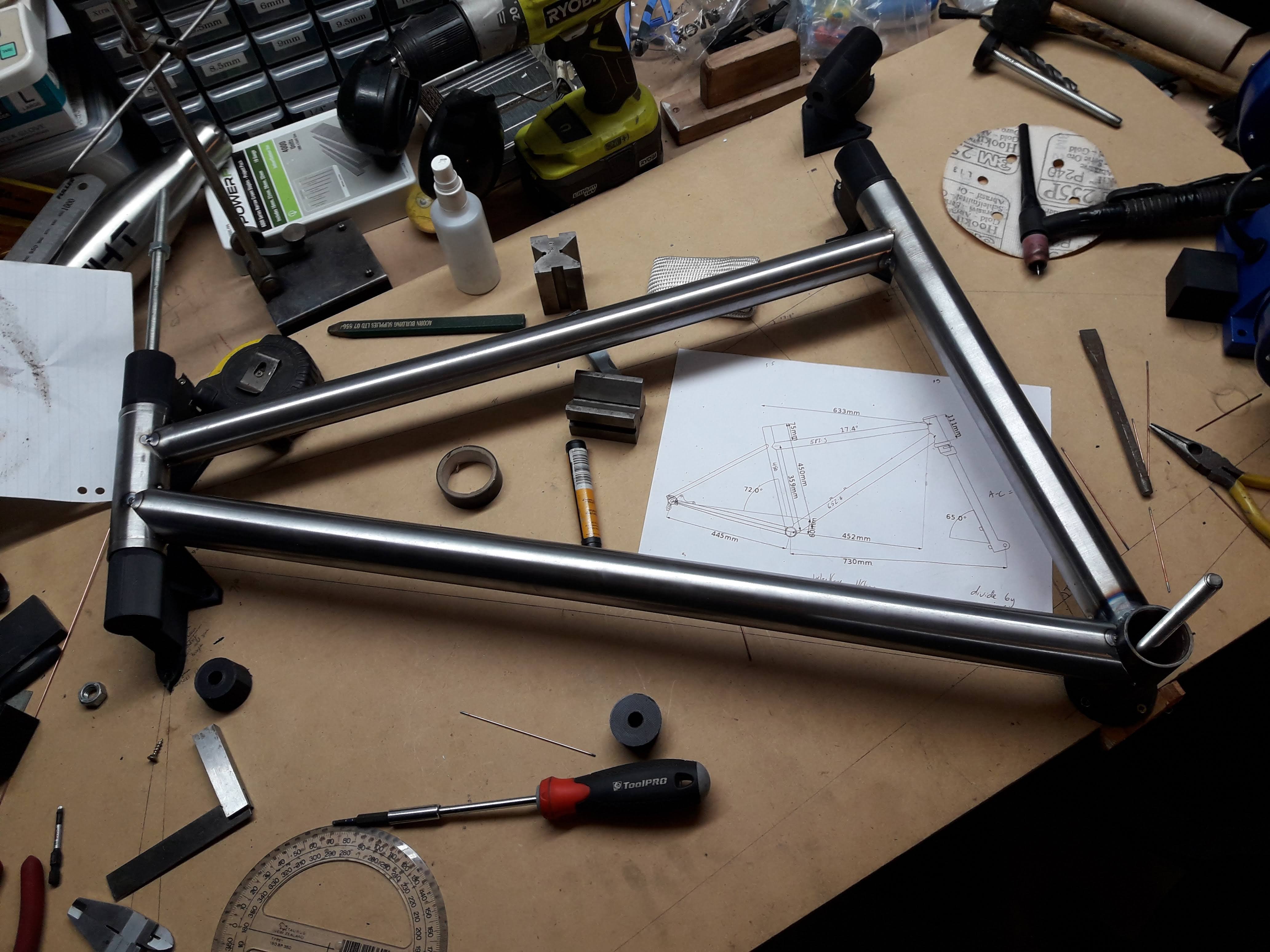
So the bike I am building is going to be a full rigid, 27.5" plus tyre mountain bike with pretty aggressive geometry. I am going to make the chainstays extra long as both of my mountain bikes have short chainstays (435mm and 425mm) and I would like to see how the handling is with a longer chainstay length. I drew it initially on the free version of bikecad, which is super annoying as they don't include all the measurements, no doubt to try to get you to buy the full version. So I printed off a picture of the frame with as many measurements as it would allow, figured out the scale of the print and extrapolated the measurements that were not on the printout using some vernier calipers. Next time I think I would just jump straight to doing a 1:1 drawing on a backing plate/paper. Anyway here is roughly what I am building, the front triangle is going to be as per the drawing but I may end up gong 450 on chainstay length if the materials I have allow for it: I have ordered a rigid 1 1/8" steerer fork off aliexpress that I will probably need to cut and shut to give it tyre clearance and to fit thru axle wheels, hopefully it isn't complete garbage but if it is I will probably get a surly fork to suit easily enough. The stack height is a bit weird so my plan is to get a set of dirtbike handlebars with 75mm rise to get the height up to where most of my bikes are, and bore out an old bmx stem I have lying around here to suit the 28mm bar diameter. Initailly I used a piece of 18mm plywood as my backing board, but after a bit of measuring I found it was very un-flat. So I decided to go with MDF as it is quite stiff, dimensionally stable and best of all... cheap. So I drew the board out a second time and chucked on the bits and pieces that I have so far. I ordered 6 feet of 4130 1.5"x0.035" tubing for the seat post and down tube (with extra to allow for stuff ups) and 2 feet of 1.25"x0.035" for the top tube (no room for stuff ups, that will go in the triangle last) from AFWE in auckland and made a jig which is blatantly stolen off @Valiant to mount the tube in the lathe toolpost for coping: It did a pretty good job, need moar hose clamps for better holding power. Maybe a hole saw that has all its teeth would help too as it snagged at the top and gave it a bit of a ding, came out ok with a little tappy tappy with the hammer.
-
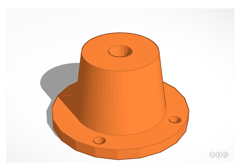
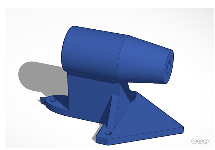
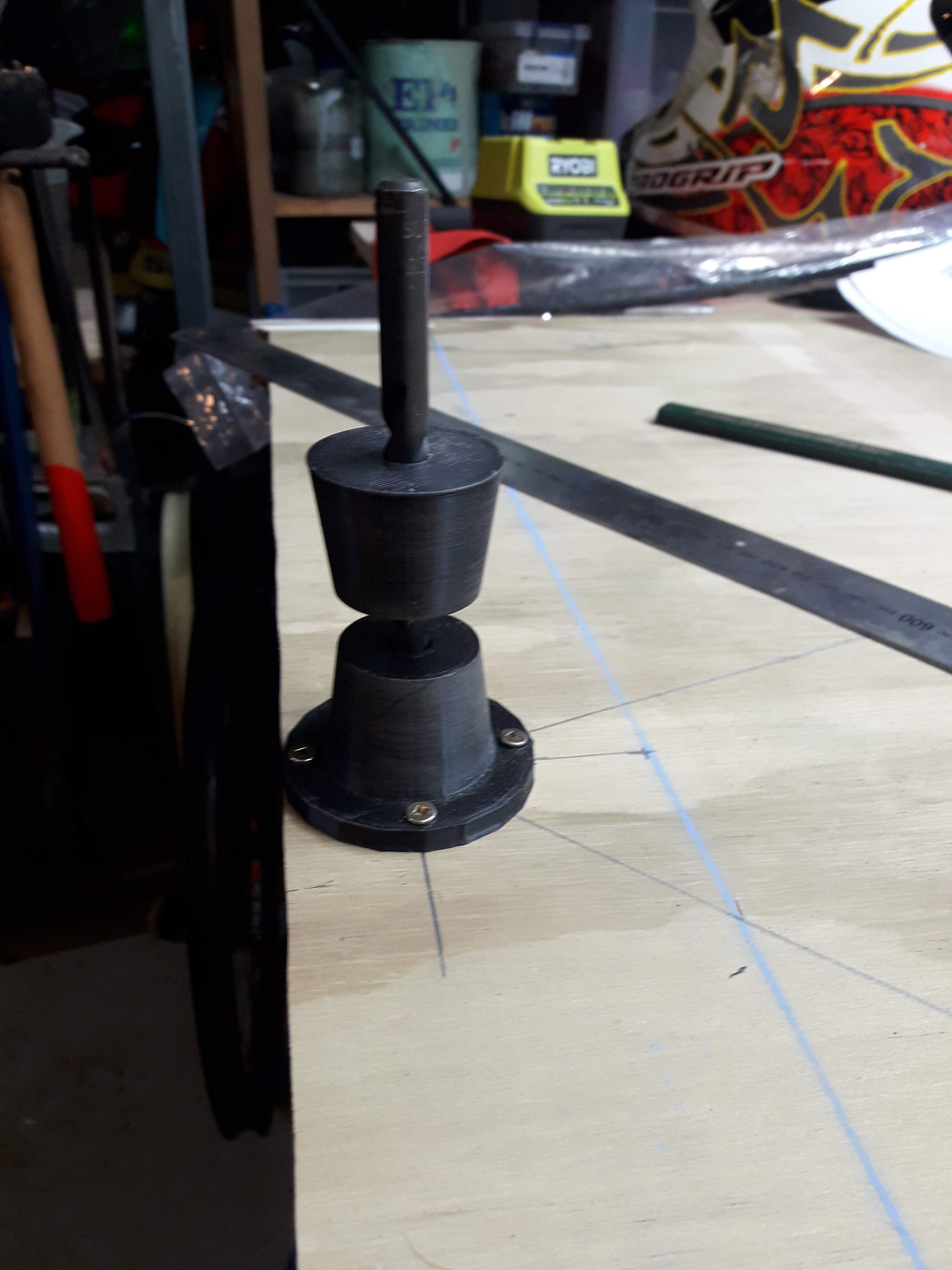
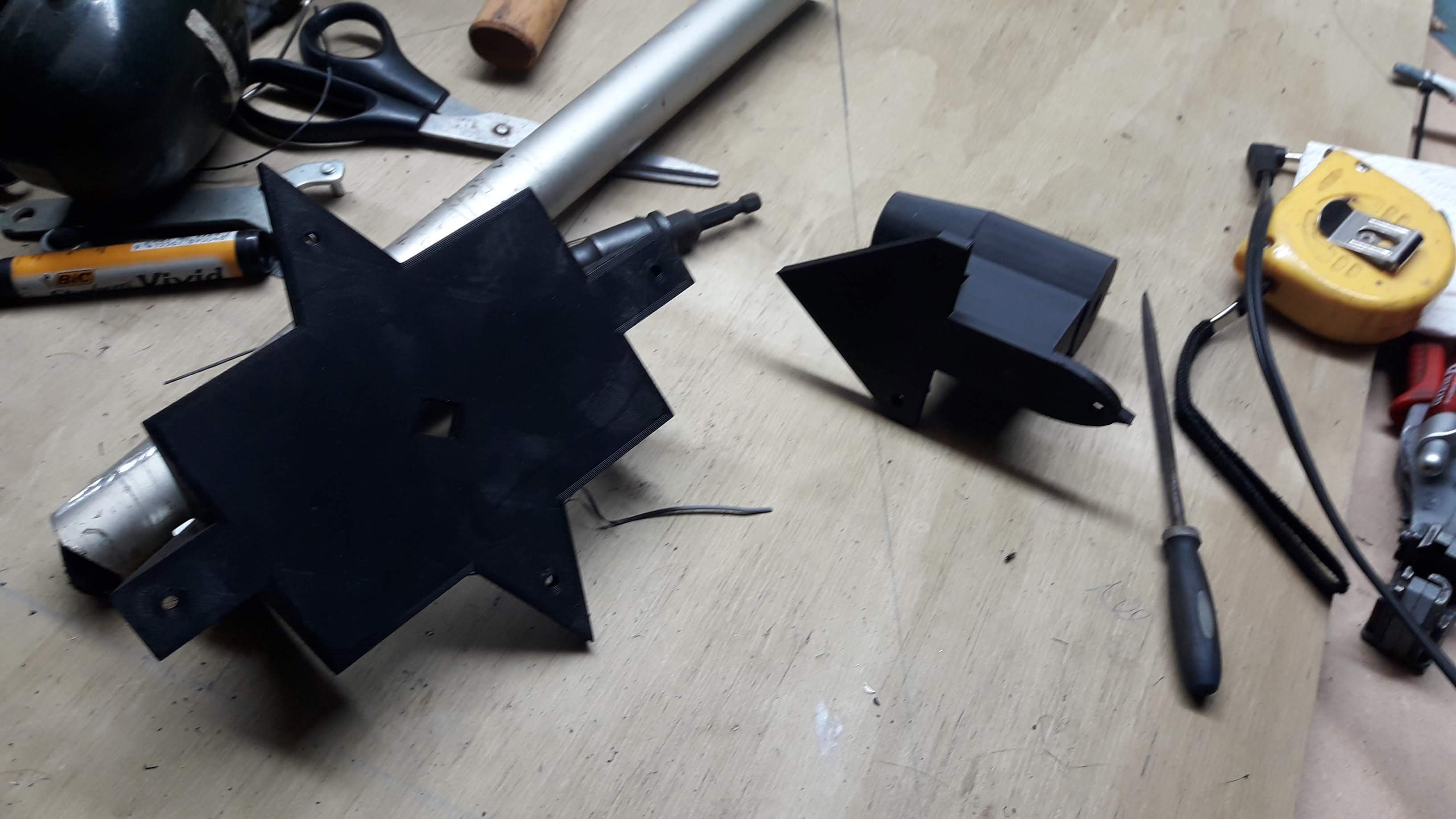
For many years I have wanted to have a go at building a bike frame and have slowly been working towards getting all the gear to put one together. The other day I was watching a video on the couch and the video quoted something that Frieburger off roadkill once said - "don't get it right, just get it running". I had a think and while I don't have the ideal equipment job, people have definitely got the job done to a good standard with worse equipment than what I currently have. So instead of getting my arse off the couch I opened up tinkercad and started modeling a bare bones frame jig. Basically something to hold tubes perpendicular to a flat plane and a mount to hold the bottom bracket vertical. I ended up coming up with these bits here: After a bit of fiddling around the centre height ended up at 58mm for no particular reason. Someone kindly donated an old chromoly marin eldrige which made me cry inside a little to cut up, however it had signs of rust in the tubes and the previous owner was not confident to reuse it. I cut the bottom bracket and headtube off it and will hopefully be able to salvage the tubes of the rear triangle too. Here's the bottom bracket fixture printed and attached to a backing board. the hole is friction fit for a 9.5mm drill bit, I just threaded in some m10 threaded rod after a quick trip to the hardware store. The fixtures have alignment arrows built into them so you can mark a line on the backing board and place them on the line fairly accurately. The larger item there is a bottom bracket fixture thing that I drew as well, I'm undecided as to wether it will be worth using or not at the moment. More coming soon...
-
My experience of changing tyre sizes (which also happened to be an ae101 but it was a levin) stock was 195/55/15 and I changed to 205/40/17 I think. Wet weather performance was much better on the narrower tyre. I found the same thing on my ae82, it had 175s on it any it hooked up in the wet phenomenally. I'm no expert but I think going wider will make things worse* *I don't know what I am talking about, anecdotal experience only. Not financial advice.
-
Pull the relay out and see if you can pop the cover off and inspect the contacts. Maybe use a multi meter to check that the relay is doing its relay-ing. Also, inspect any electtrical boards in the machine for obvious faults. Capacitor popped open, or burnt component, that kinda thing
-
It selects the voltage and amperage to suit the wire feed speed you have chosen and you have +/-20% for the voltage and inductance. For general fabrication I have set it to +10% on both and that works mint, the weld beads were a bit nuggety on the default setting. for panel/rust repairs I set it to the lowest feed speed and -10% voltage and that worked mint too.


.jpg.1596cadcd34c392ce2a5a01cab726e0d.jpg)