


Adoom
-
Posts
2199 -
Joined
-
Last visited
Posts posted by Adoom
-
-
On 03/08/2018 at 15:15, ~Slideways~ said:
I only just got back into working on my projects again and had a long list of stuff to get done with a vague idea of maybe getting it to a state that I could trailer it to a track day in September for some testing.
Which what when? If you go then I must go too.
-
14 hours ago, flyingbrick said:
To be honest i have no idea- no drama for me to get you a price on monday tho. Ya may even be surprised.
Im no material expert but reckon gauge plate could be great for this as the laser will make the cut edges super super hard. (Just experience has shown this to be the case)
Cool, I'll wait for Monday then. Thanks!
-
How much do you think it will cost if I got 12 at 2mm thick to stack and make the ~1inch width?
-
1 minute ago, flyingbrick said:
Do you need someone to draw it? I'll do it for you.
If you want to, that would be great! I've never got anything laser cut, so I need to find out if there is someplace near me/work that does it.
-
 1
1
-
-
Just now, peteretep said:
TBH I have been living in the dark ages, I haven’t seen an automatically lifting saw
You must be, this thing is from the 50's
-
1
-
-
Maybe this does not apply.... but I installed a new 'hybrid' puk clutch at the same time as a machined flywheel.
It would not fully disengage. With the car on stands, the wheels were still turning when the clutch was disengaged, but you could stop the wheel with very light brake pressure, or even holding on to the wheel.
Eventually discovered that the clutch needed to bed in to the flywheel a bit, then it was fine. Like jack the car up, start it in gear, disengage the clutch and hold the brakes on for a while. That improved it a bit, so I took it for a short drive and it got much better/stopped doing it.
But maybe you have a different problem...
-
Maybe I will put it in the too hard basket. The previous owner said he could never get the lift function to work, but he had cut a shitload with it despite that.
-
1
-
-
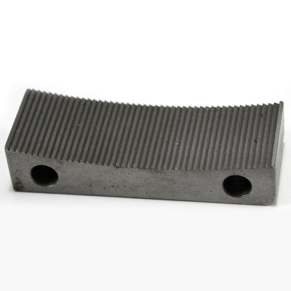
So I bought an old as power hacksaw. It works okay, but it's missing a piece of the mechanism that lifts the blade on the backstroke.
The saw has no branding, but it's a model that has been sold under many names. Sears, Craftsman, Dunlap, Excell, Atlas, Covel, etc...

The missing part is the ratchet feed block. It's intended to be replaced when it wears. But it's NLA.
It looks like this.
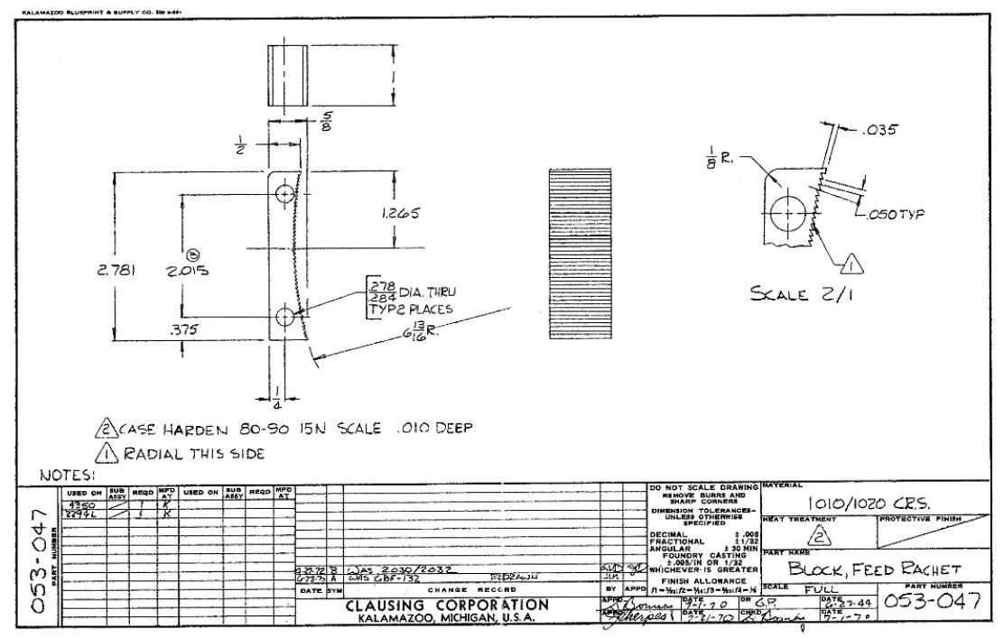
The manufacturer released the engineering drawing for the part after it was discontinued. I wondered if there is enough information to model it to use a cnc mill to replicate it? And would it be economical to make?
-
1
-
-
On 10/07/2018 at 20:40, SOHC said:
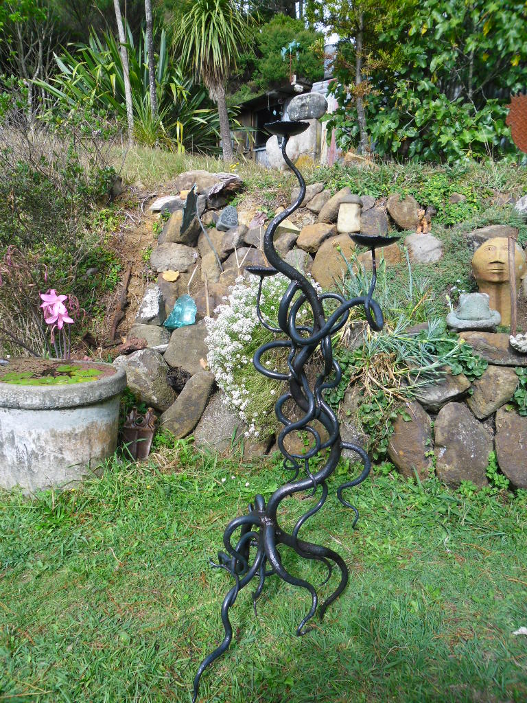
Where's the manga girl that goes with these tentacles?
-
3
-
-
14 minutes ago, Seedy Al said:
There website makes me nervous. No real indication of who or where they are. ....
You are right, it is weird. They also say they do "local pickup".... but where??? Their domain name appears to be registered as being in Wyoming... if that's what "WY" stands for.
EDIT: Oregon apparently. https://www.facebook.com/pg/RichKobliha/about/?ref=page_internal
-
3 hours ago, tortron said:
Dodgy solutions question
I have a 2m length of 10mm thick steel angle iron
I am trying to dress the lips so that it will sit flat when placed point up on a surface.
(It's going to be the clamping section of my sheet metal folder, needs to be flat and flush with the sheet for a crisp bend)
Right now I have made some v blocks and attached them to an angle grinder, so I can place it in the V and slide it up and down and it will in theory grind both lips to a similar height and angle.
But goddam it's slow going.
Maybe a better/coarser disk?
Could you just weld the angle to a length of flatbar? So the cross section becomes a triangle rather than an inverted 'v'.
And.... you are building a sheet metal folder 2m wide? Pics!
-
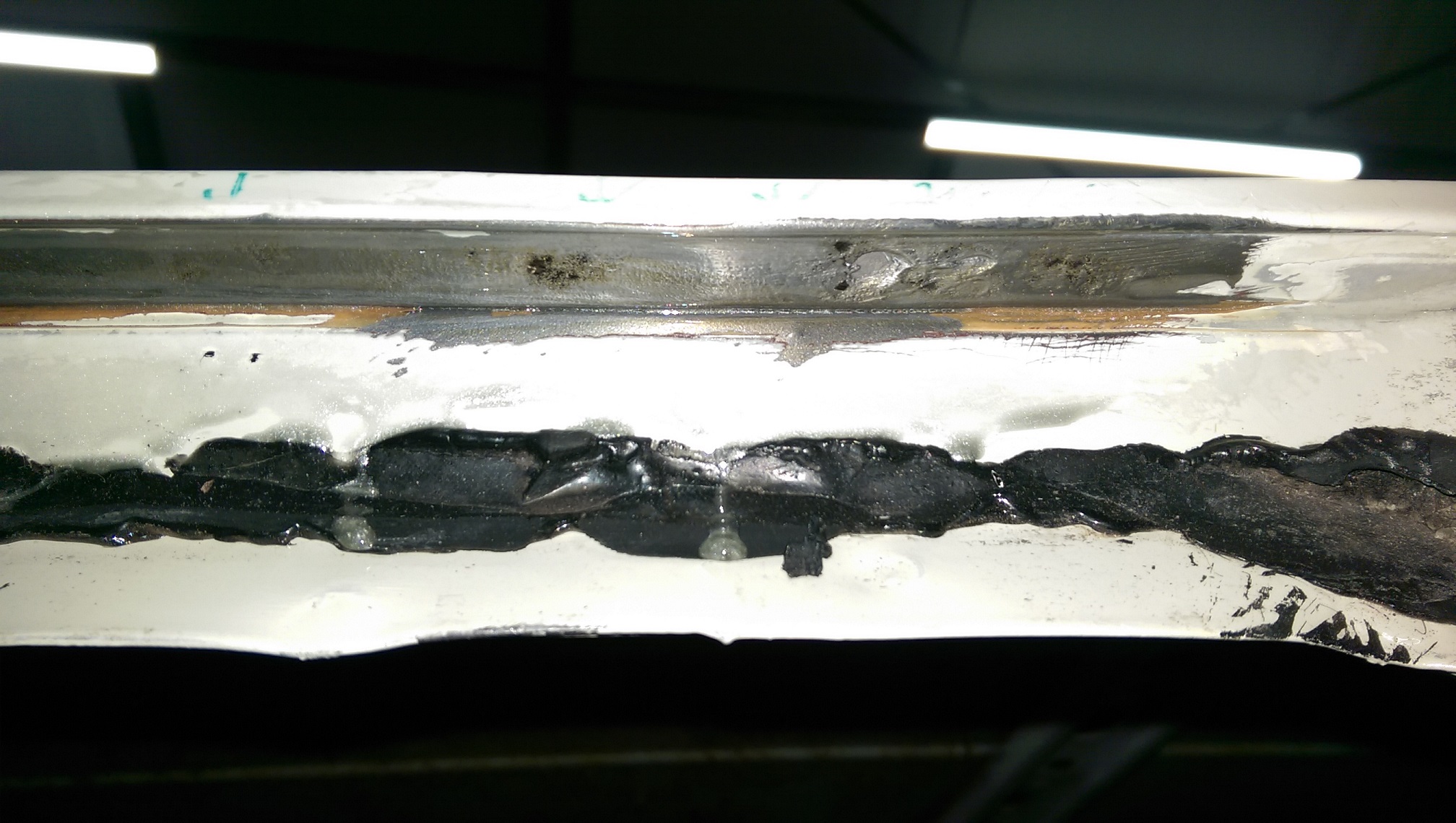
Last WOF they pointed out some rust starting under one of the rain gutters. Since the next WOF is overdue, I thought I'd better have a look at it.
While I had the window out, I had a look at the rust I had painted with POR15 almost 10 years ago. It hadn't advanced, but since I was there, I decided to fix it properly.
After wire brushing and using metal prep/acid and painting a little por15 silver. A few tiny spots I didn't manage to get off.
Found that the 'corner' of a cylindrical carbide bit in the die grinder is REAL handy for cutting the short lines where a cut off wheel won't fit. Just grind a groove till it breaks through.
Still need to grind the welds back...
-
8
-
-
39 minutes ago, flyingbrick said:
I considered buying a roller for my tractor but did some reading and found out that they actually weren't any good for what i wanted (flattening the ground out)
I heard similar. Like you have to fill holes not flatten bumps.
-
1 hour ago, Mof said:
What could I put in them heavier than water, lighter than concrete?
Less concrete?
Sand and water?
-
1
-
-
7 minutes ago, XSDUP said:
Doom.. you crazy
i like it.
Thanks, but you're doin' it wrong. On OS, we have separate discussion threads for projects. It keeps the project threads nice and tidy.. Here is the discussion for this project. https://oldschool.co.nz/index.php?/topic/57912-adooms-1972-triumph-2000/ Write your words to tell me I am cool there.
-
1
-
 1
1
-
-
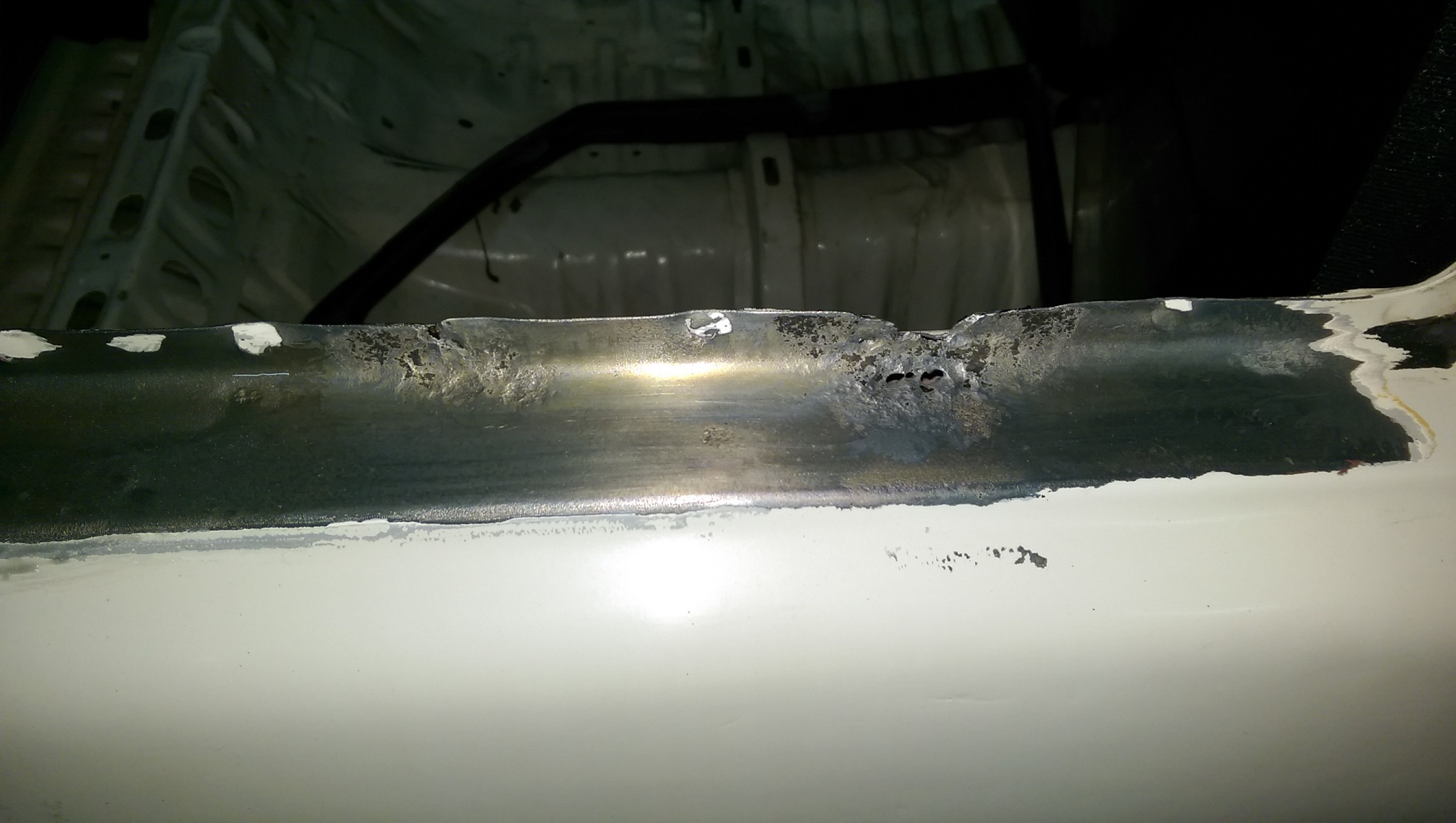
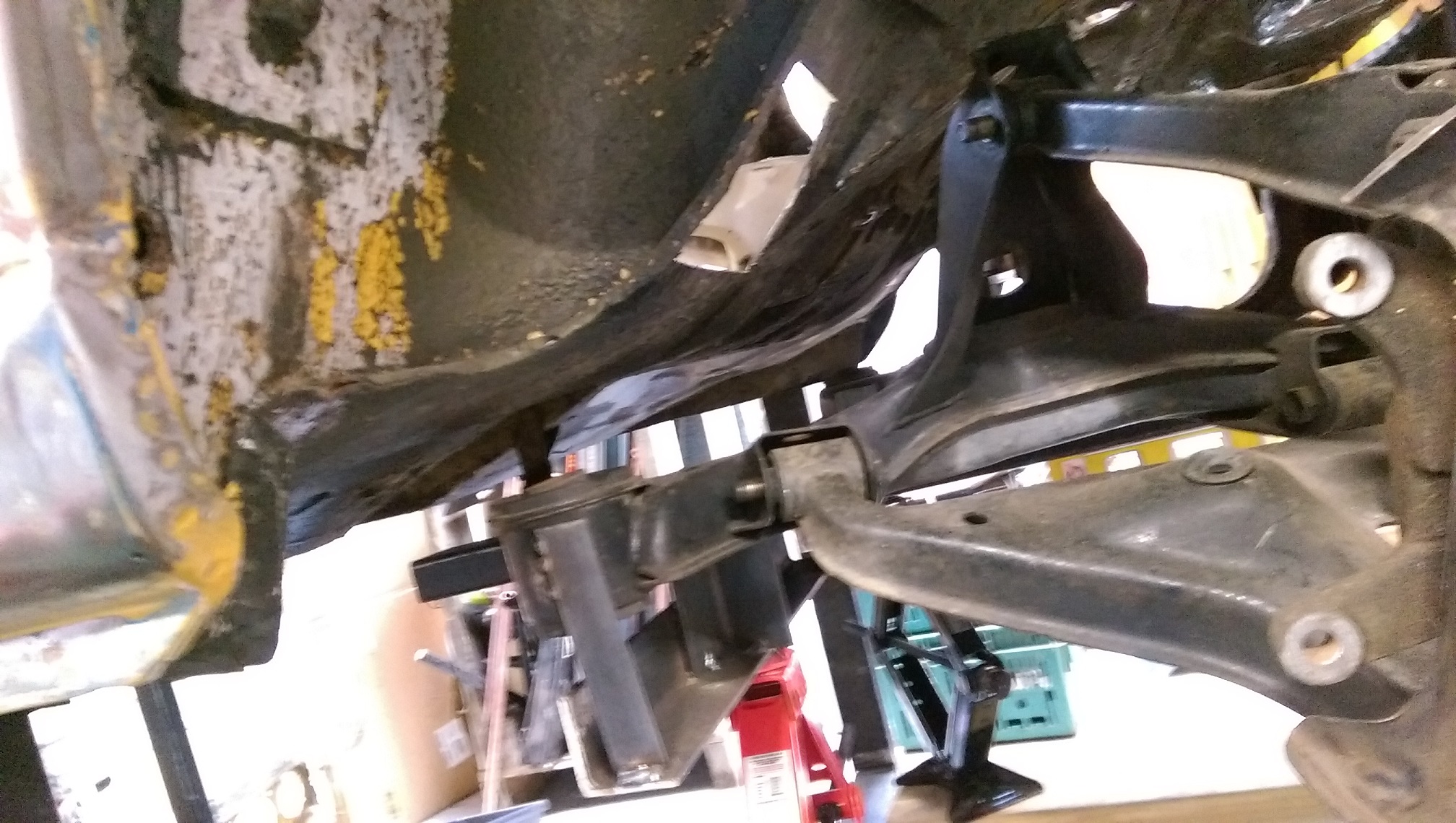
So I cut the box section a bit, to lift the subframe slightly and narrowed about a 50mm section at the end of the chassis rail where the box section joins on to it.
So now the top/rear suspension arm has more travel before it hits the chassis rail.
After looking at a bunch of photos of Triumphs to decide on a ride height that looks okay. I decided that the wheel centers should line up with the top of the sill/bottom of the door. This makes the rear look really low and the front still look quite high, but the car is level. I get about 50mm travel before the front is on the bump stops and about 55mm at the rear before the arm hits the chassis rail.
My special tool for making scissor jacks go fast. I'm using the scissor jacks to lift/position the subframe and also the suspension.
-
8
-
 1
1
-
-
Also discovered that Silvia wheel stud thread pitch does not match any of the wheel nuts in my drawer of wheelnuts. Think they might be 12X1.25 or something.
Anyone wrecking a 90's rwd/awd nissan something(afaik they are all the same) and can knock out the subframe mounting studs for me? They are pressed in like wheel studs. You need to cut a hole in the panel behind the stud so you can get it out.
-
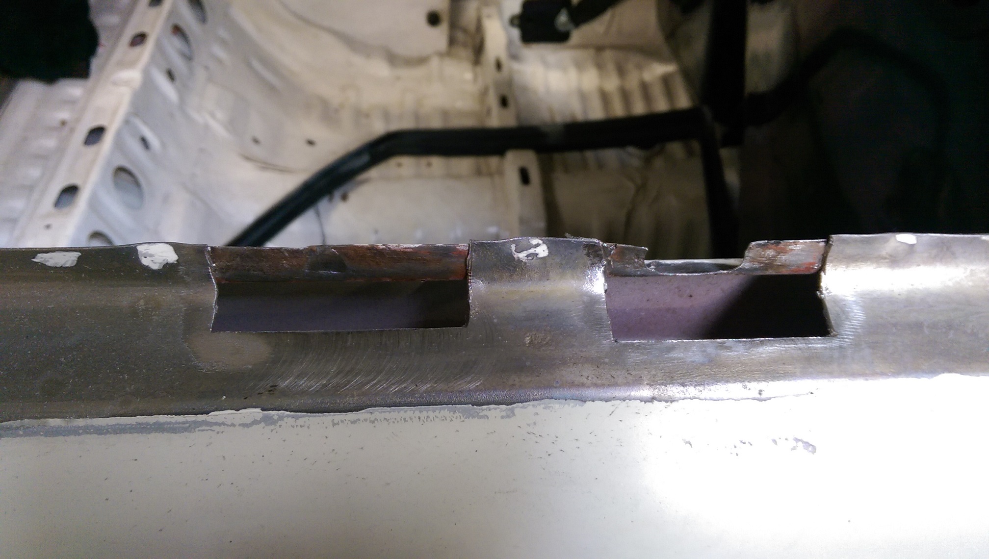
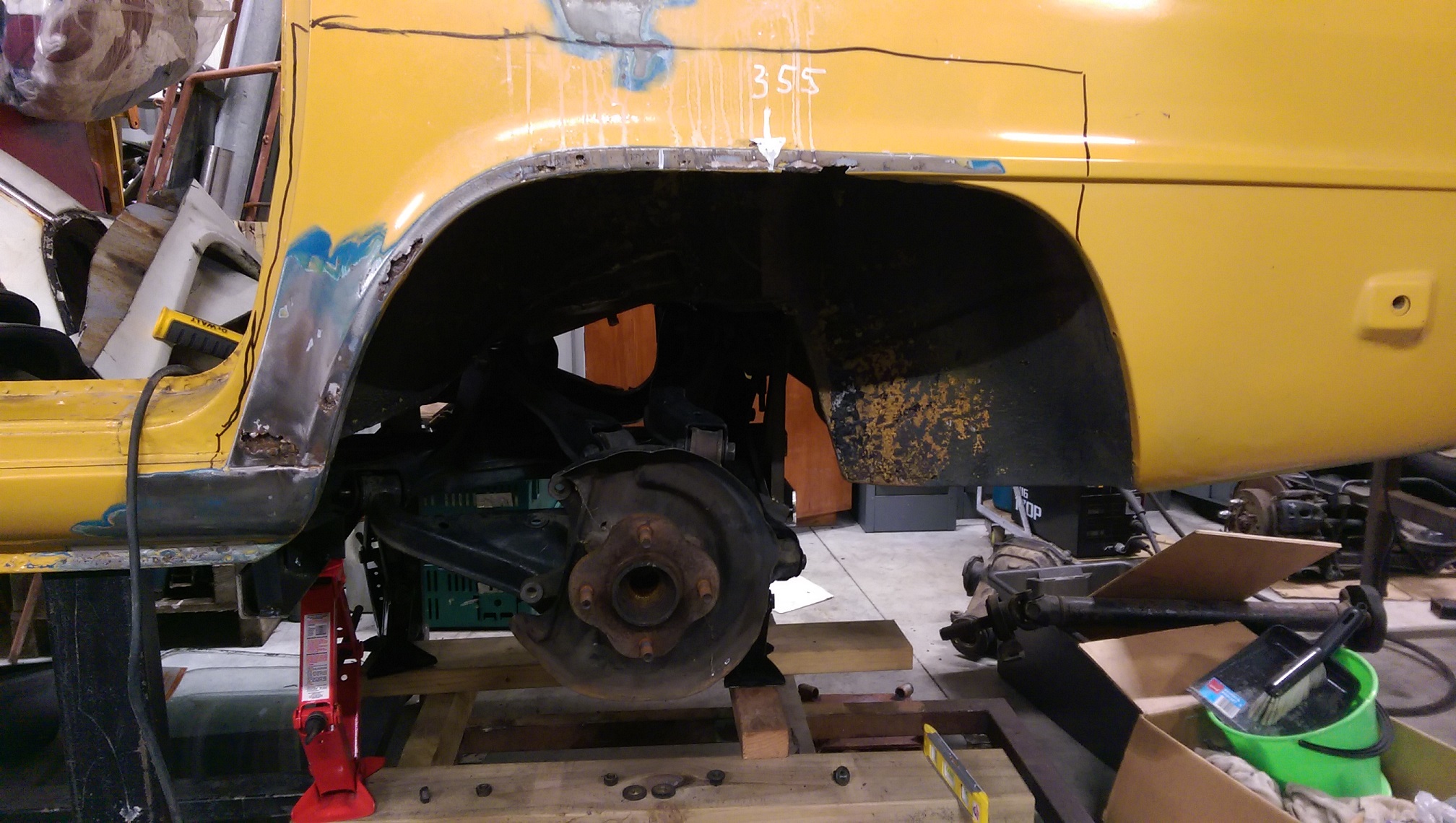
Snip snip snip.
Moved the subframe back so the wheel hub is in the factory location. Still need to work out if the subframe is high enough.
There is a clearance issue for the top rear arm which means there is only about 20mm of upwards travel from what seems like a good lower than std ride height. Making more clearance does not look too hard.
I was thinking that the front mounts hang a bit low, so thought the subframe might need to be higher. But then I measured the std front mounts on the white triumph and they hang down just as far but are more outboard.... Still not decided yet. There is room at the front and above the top/front arms to raise it about 40mm without cutting.
You can see the temporary bit of angle to show where the diff mount cross member needs to go. Lots of room for it. Even if the subframe is raised further.
-
3
-
-
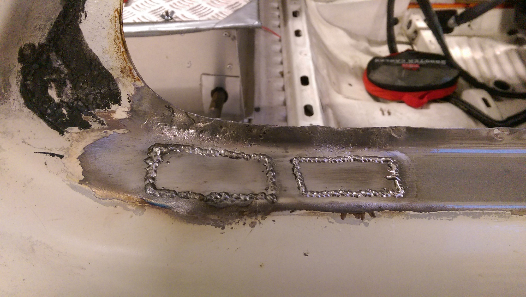
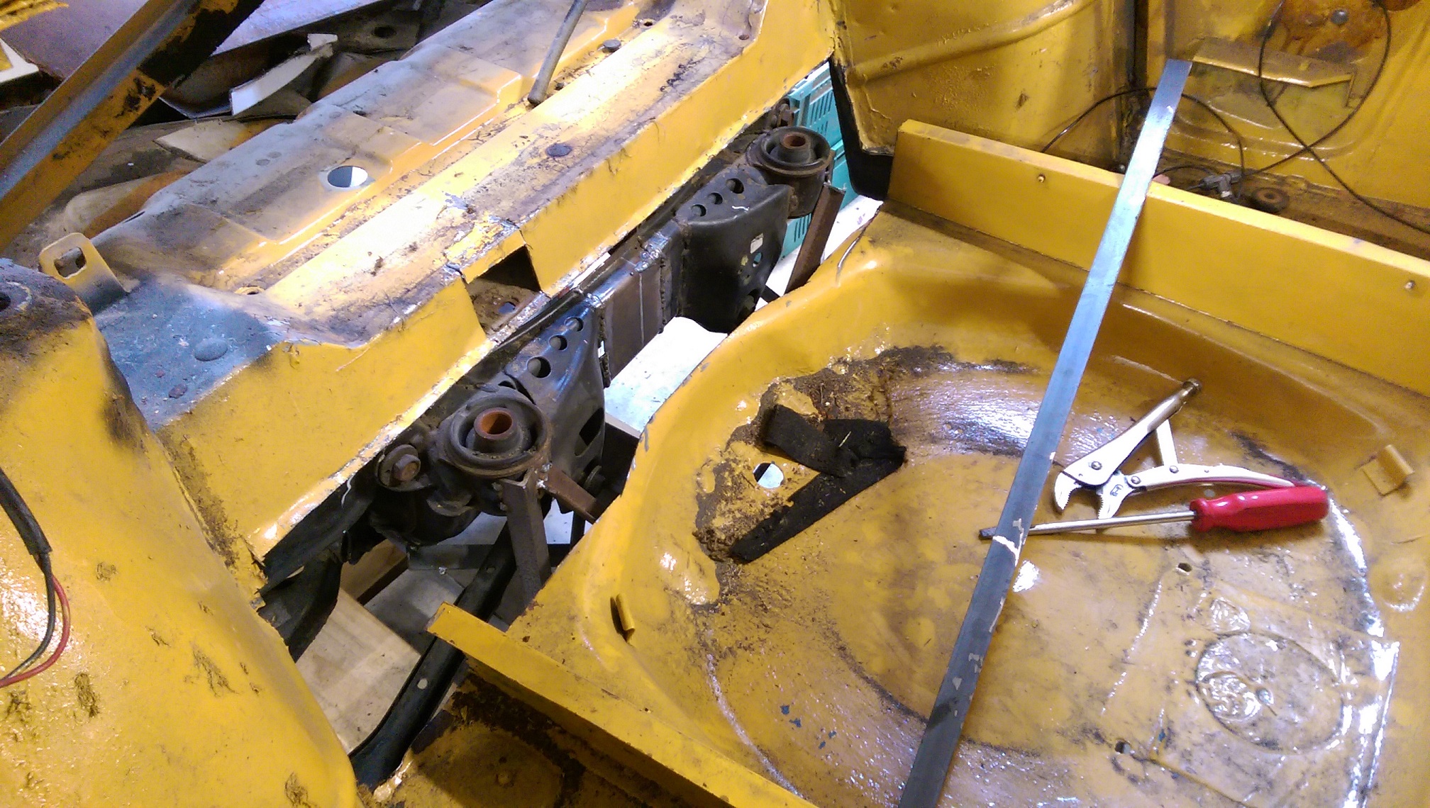
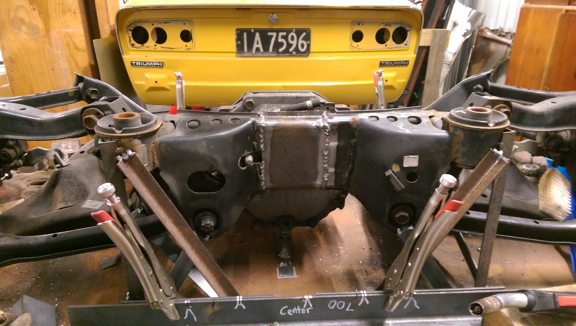
So I welded a temporary bit of metal for the front diff mount cross member, so I can trial fit and see how much space there is available for the cross member.
I put some bits of wood on a wheeled dolly and 3 scissor jacks for raising and leveling the subframe under the car.
As it is now, the subframe is wedged in there, and level, and I think the height is okay so I don't get crazy camber when the car is at ride height.
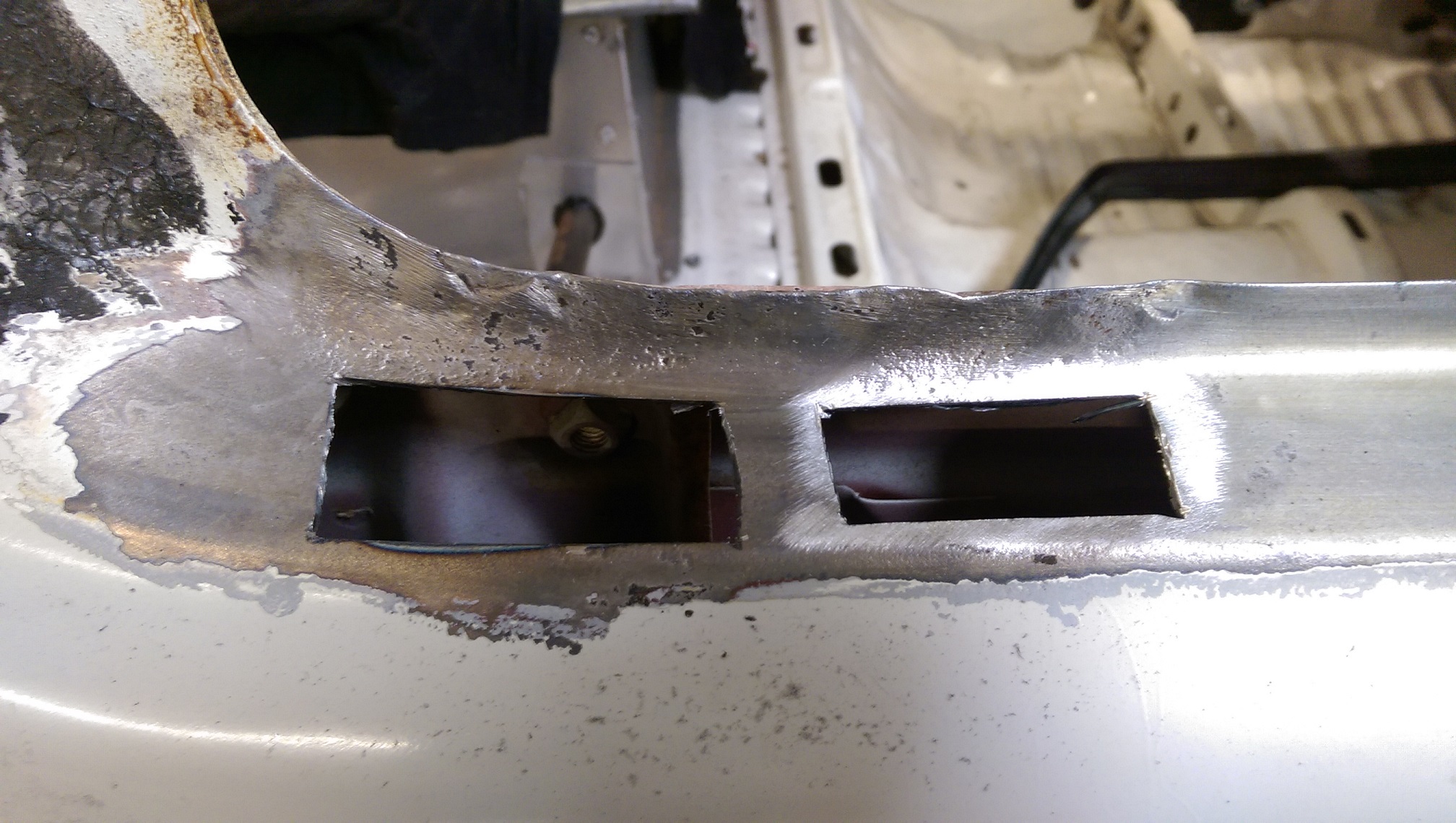
But, it needs to move 90mm further back, which will give me lots of room at the front, I won't need the two holes I have already cut.
But I will need to extend that existing box section further into the boot space. Fortunately, there doesn't appear to be anything stopping me from doing this. I may still even be able to fit the spare wheel!
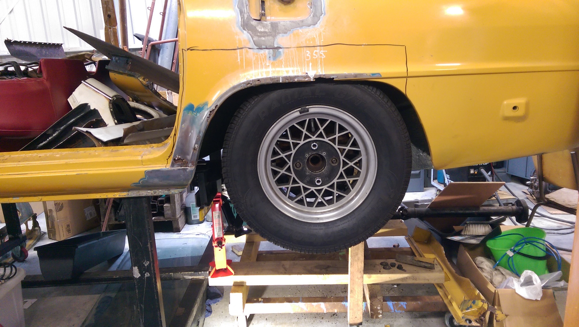
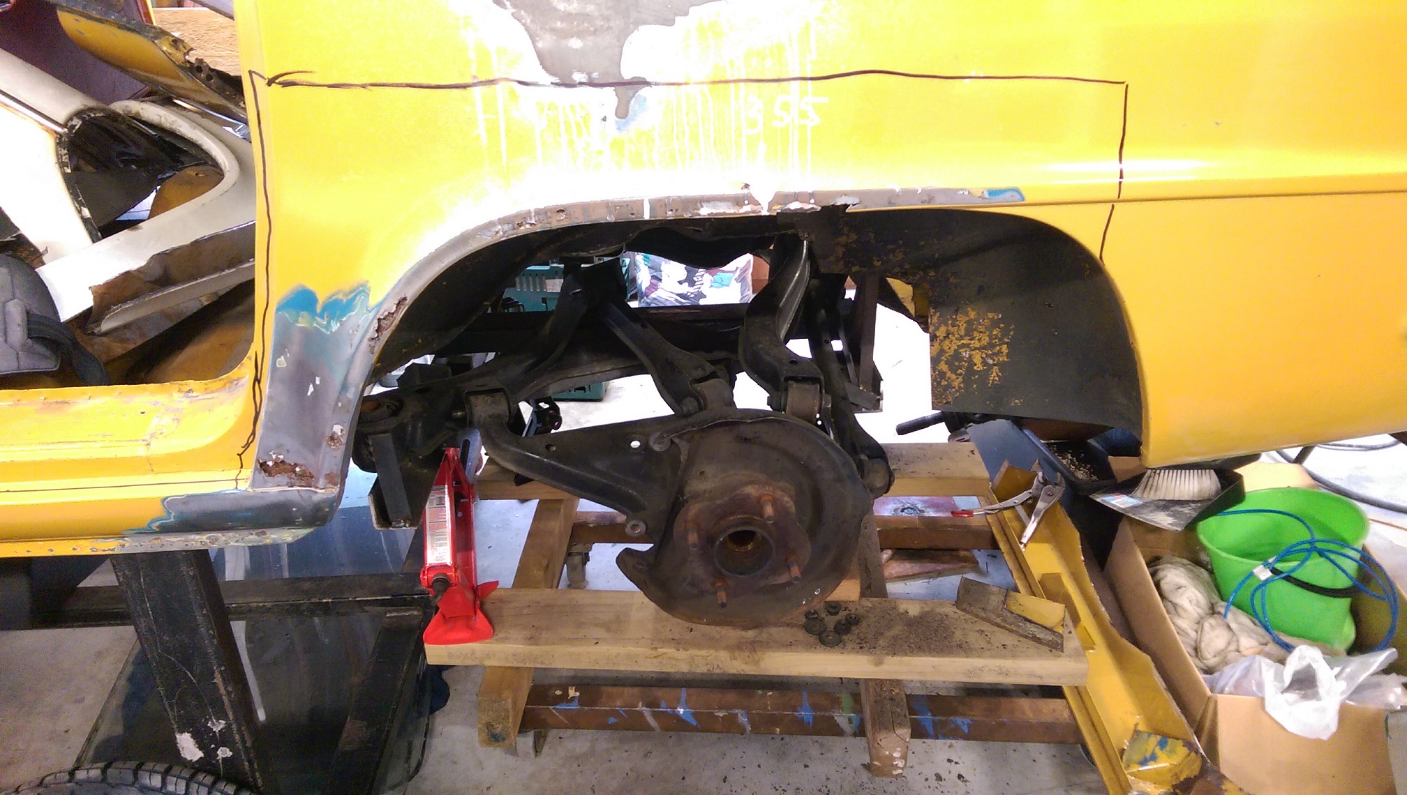
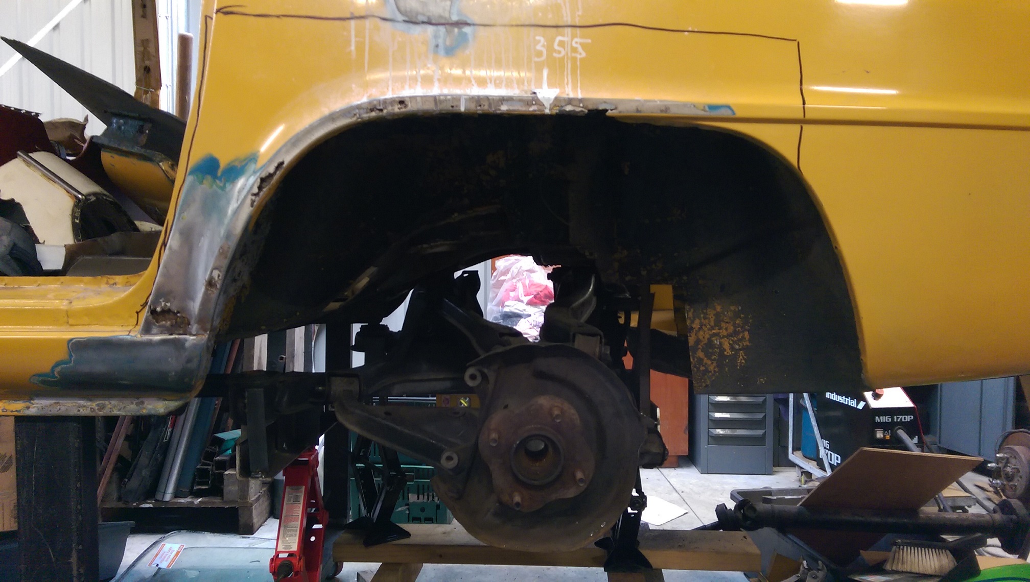
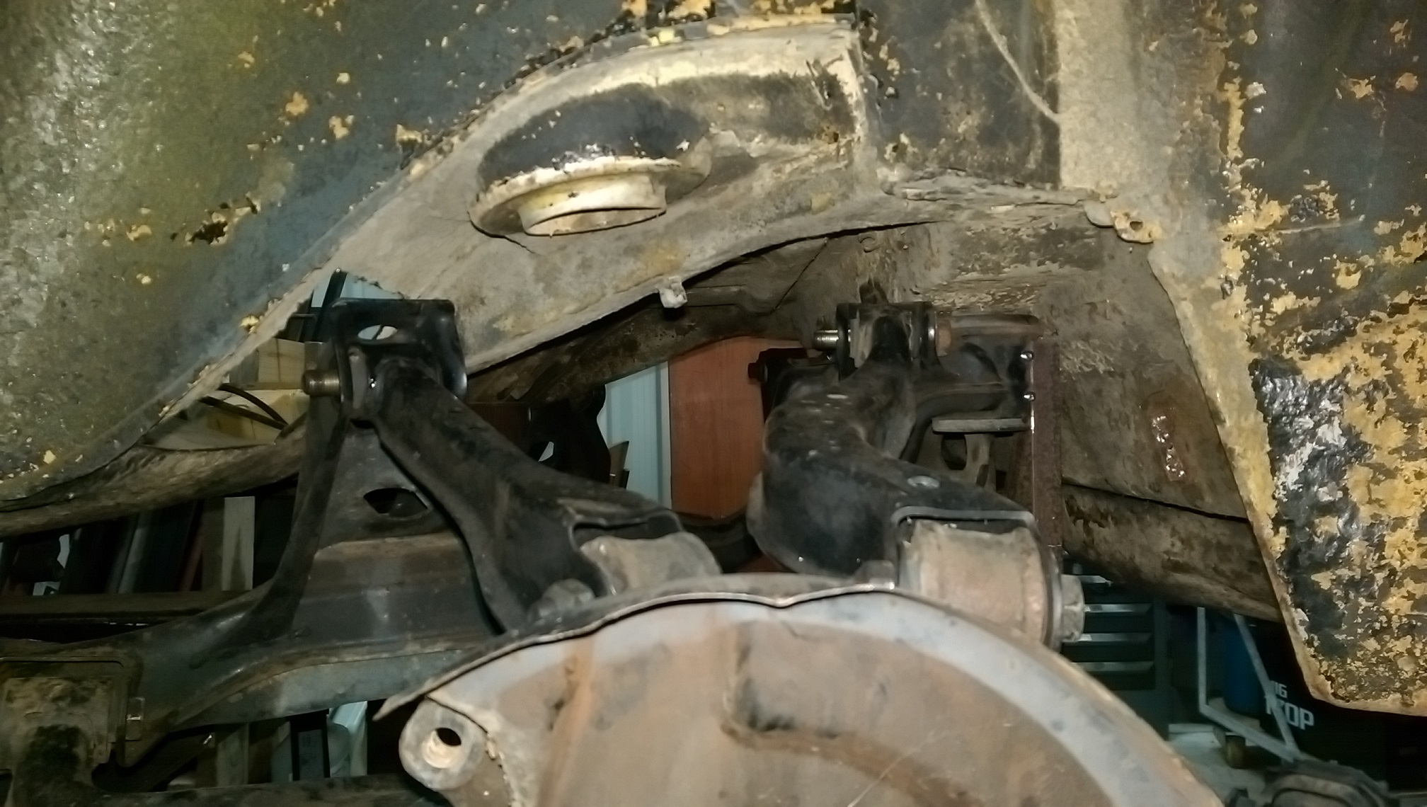
See I have marked where the wheel hub is on top of the arch, and where it needs to be. This isn't full suspension droop, one of the braces on my jig is in the way of a suspension arm moving any further. Aaaaaand with the subframe 90mm further back, the shock mount on the back of the hub is directly below the shock mount on the body. Hopefully I can find/make some coilovers that will fit in the available space. I'd like to avoid making the existing shock 'towers' larger because then I would have to also modify the fuel tank as it is a tight fit between the shock towers.
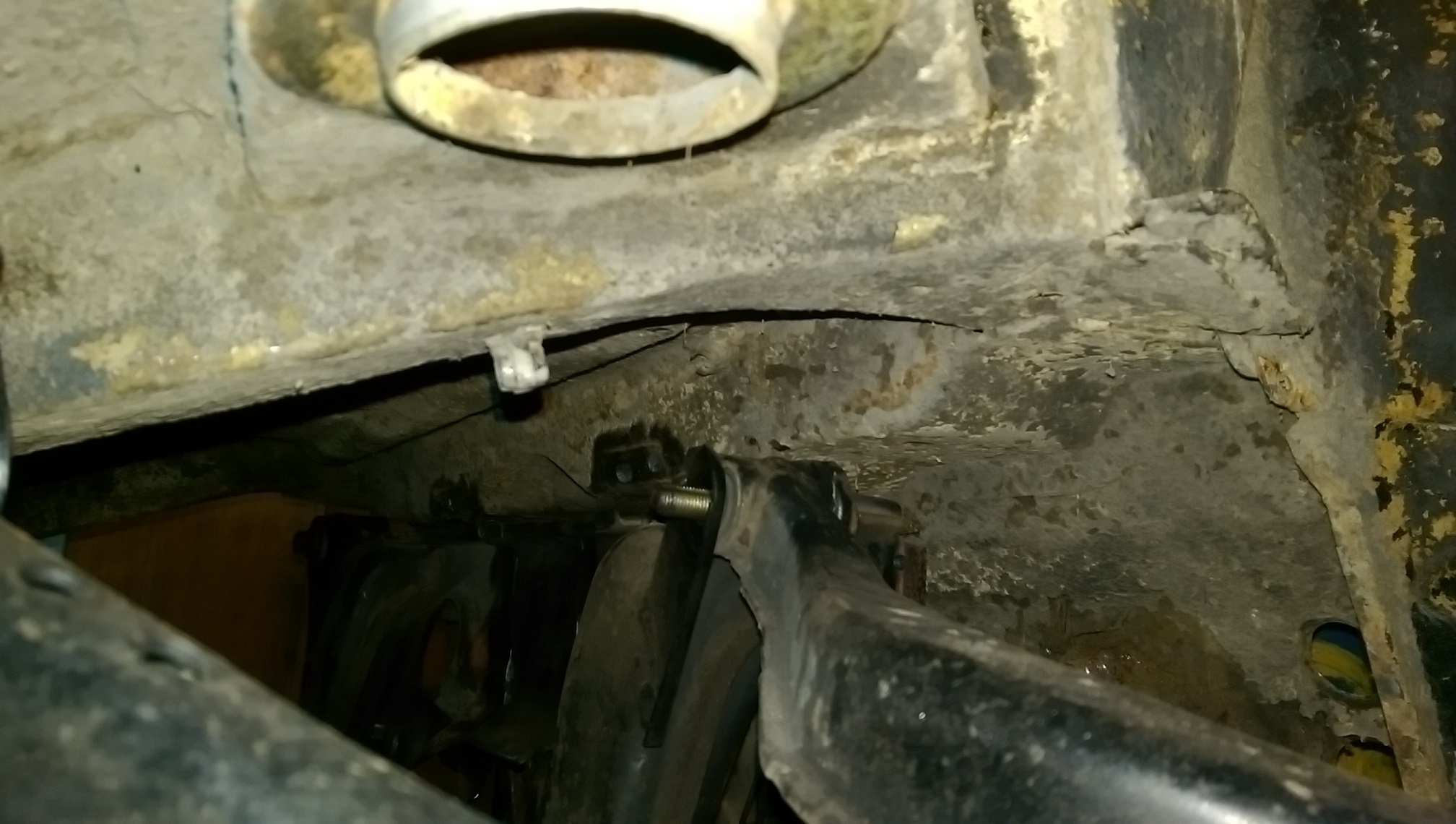
The rear subframe mounts are hard up against the existing box section. I have already removed the original mounts/studs from the box section to get the subframe up this high.
Once it moves 90mm further back, there will be plenty of clearance for that front/top arm mounts so the hole is not required. Not visible in the photo, but there will also be ample room for the diff mount cross member.
Not sure how to make the mounting point for the front mount. Ideas so far are: strengthen the floor with plates and build a mount point down from the floor. Or make another box section/outrigger to support the subframe mounting point.
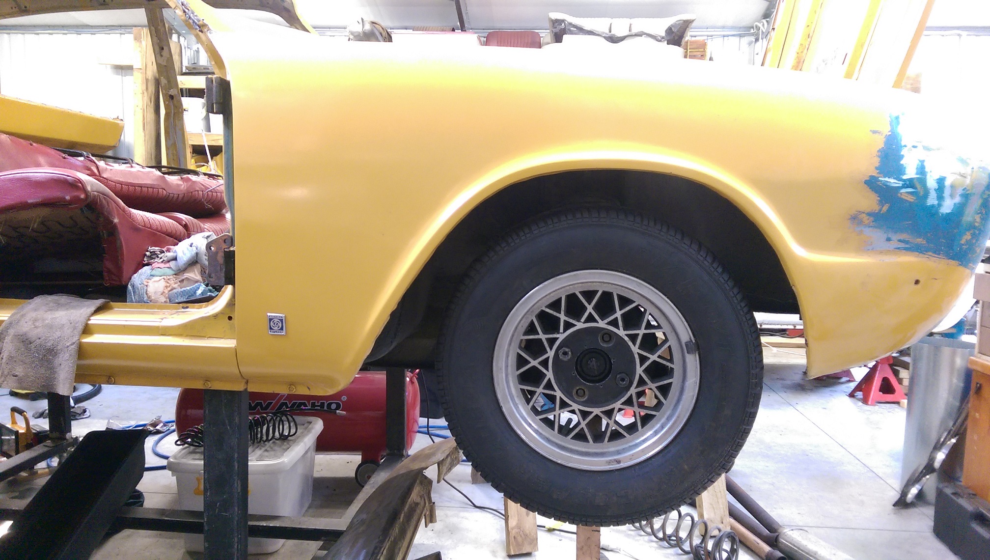
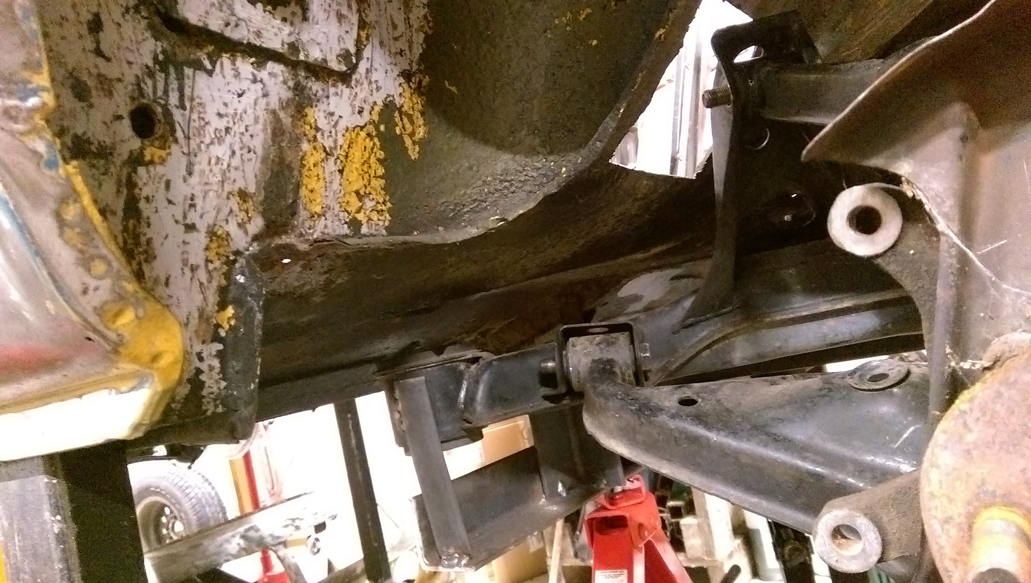
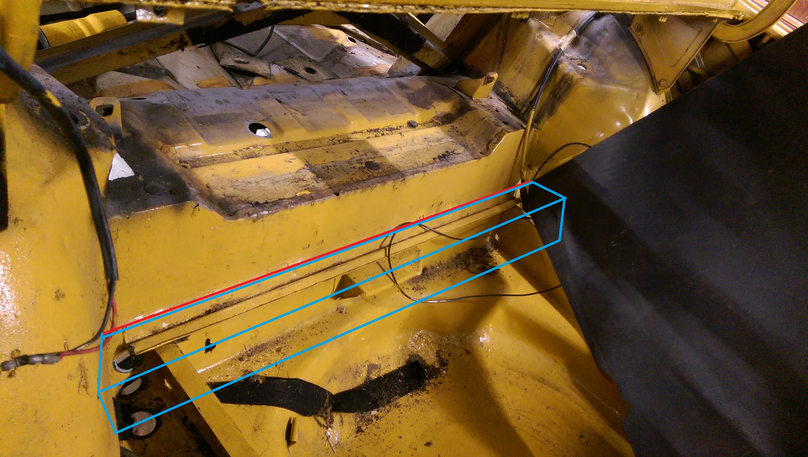
Here's another picture of that existing box section.
The red line is where the bottom of the existing box section is under the car. The blue box is where the 'new' rear part of the boot floor would be so the subframe can move 90mm further back. I need to think about how to best make 'whatever' that the subframe rear mounts will attach to.
-
1
-
-
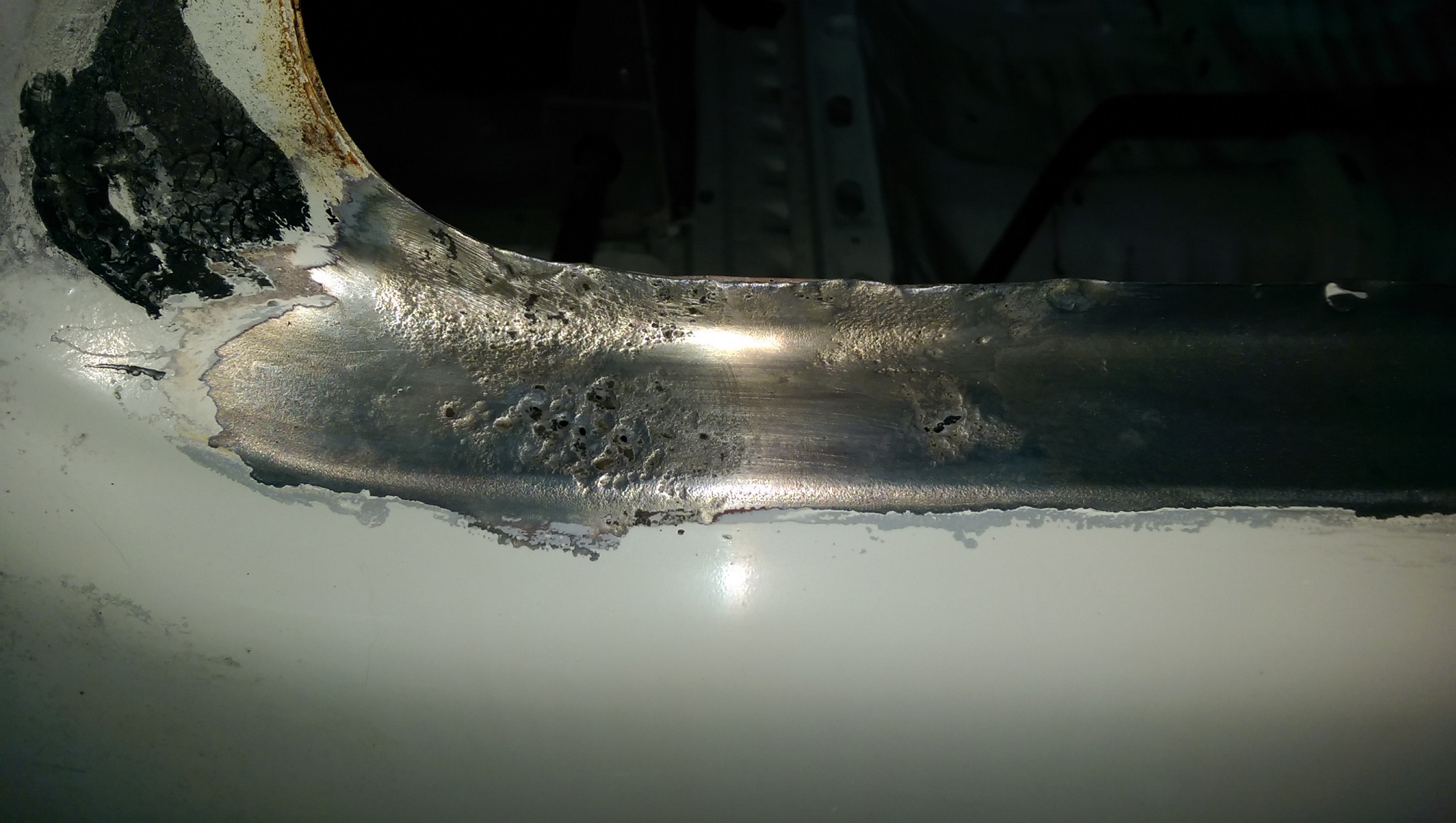
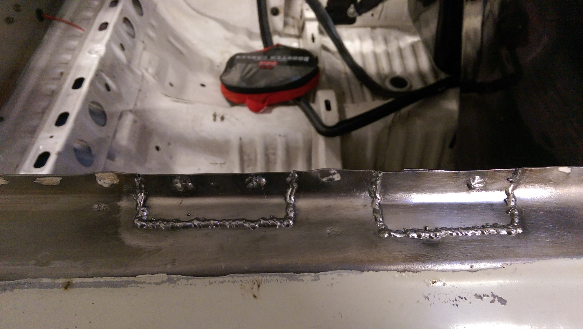
Filled in this gap.
Still needs to be double skinned on the backside, as per original.
And need to cut a hole for a large diameter tube for the rear mount.
-
3
-
-
On 29/04/2018 at 21:50, 66gt said:
Resene do a marine grade epoxy which is as hard as the hobs of hell. I’m using it on the underside of my Cortina and then top coat over it
Link? Name?
-
So on Friday I went to Pick a Part, on my break, to get a pile of $12 scissor jacks to use for positioning/levelling the subframe when it comes time to trial fit it to the car.
I'll have to make a box or something to put under the jacks cause the yellow car(I'm using it for the trial fitting/cutting) is way up in the air.
While at Pick a Part I found a Stagea, which has the same diff(wrong ratio) that I am using, but it has the driveshafts I need, specifically the inner CVs because they have the 6X1 bolt pattern for my 350Z diff.
So I did a mission(and drove over the bloody 'takkas again) on Saturday morning to get them off. Could have done with a 32mm long series socket to get the.... hub nut off. But I managed to crack it with the breaker bar before I completely mangled the bit of the nut I could reach with the short socket.
$64 EACH!! I'm surprised they didn't charge me separately for each bolt too. But new one's from Rock Auto would be ~$300 landed and then I still have to make custom shorter shafts. The CVs don't appear to be available separately.
-
5
-
1
-
-
5 minutes ago, Seedy Al said:
apparently I do!
There is not much of that I think I could use. I was planning on cutting out a one-piece flange with the plasma cutter and getting some mandrels.
Pass, but thanks anyway.
-
17 minutes ago, Seedy Al said:
Hey man just letting you know I have some spare log manifolds that would be perfect for cutting up (have already been modded) if you are interested.
$100 for the pair.
Other wise
Keep up the good work!
Got a photo?
Of the manifolds!


 i like it.


Making a part for power hacksaw practical?
in Tech Talk
Posted
so $83.16 + $11 + gst? for 12 of them made from gauge plate?