


Adoom
-
Posts
2,279 -
Joined
-
Last visited
Content Type
Forums
Downloads
Events
Gallery
Posts posted by Adoom
-
-
What numbers/specification needs to be on the side of my 5/16 Fuel Injection hose?
-
3 hours ago, 87creepin said:
Had a chat with an engineer, who said “a lathe is the only machine that can make itself”. Well how about a shaper then?
Nope only a lathe.
I never really got that... How do you make the bed and the ways and the carriage...?
-
On 18/04/2025 at 02:21, Jaffar said:
Just signed up to look at the Bugatti builds and noticed this.
If you are still proceeding with the swap I can give you a few tips about the installation of an LY7. I have finished installing one of these in one of Stuttgart's finest.
They are light, lots of power and torque (even more if you go stand alone ecu), compact, lots of cheap bits, easily replaced for bugger all if you blow it up and very long lived engine if serviced properly (like all modern motors). Underrated.
Cheers.
Other than a lack of time and money, I think my main issue will be getting it to run with the factory ECU and keeping as little as possible of the commodore wiring and modules. I found a guy over near Palmerston North who says he can 'recode' the appropriate modules and ECU to make me a 'kit'.
Thanks for the tip about the VE sump, I'll have to have a look.
-
On 17/03/2025 at 07:44, locost_bryan said:
You're right, Shell SAE 40 oil.
The poster of a guy on an electric guitar would date it at least late 60s, more likely 70s, looks more like Jimmy Page than Jimi Hendrix.
I'm 96% sure the left cabinet says led zeppelin with what looks like a 'Flash Gordon' style rocket, or several zeppelins. and the right one says Van Halen across the bottom with enough blurry space for "Eddie" in front of it.
-
 1
1
-
-
On 06/04/2025 at 15:52, kierbear said:
Had enough of crotchet but pleased with the outcome (filthy parts car seats)
That looks like it takes AAAAGES to do.
-
 2
2
-
-
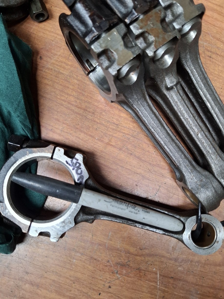
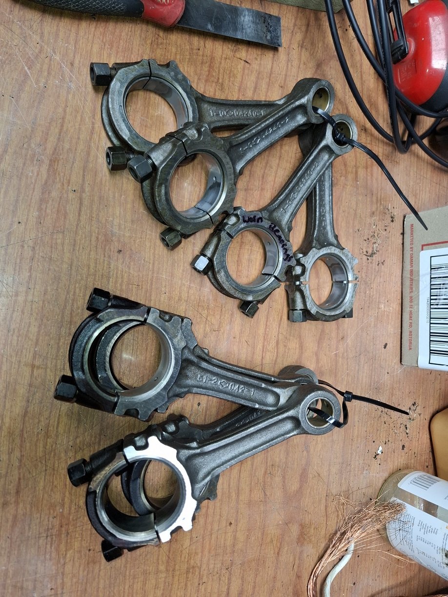
1 minute ago, ~Slideways~ said:
Haha is a sharpy the new banana-for-scale?
I had one conveniently within reach.
-
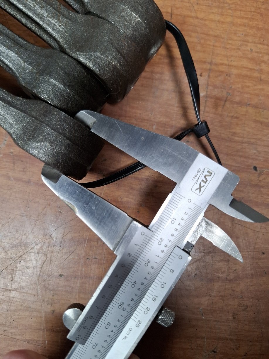
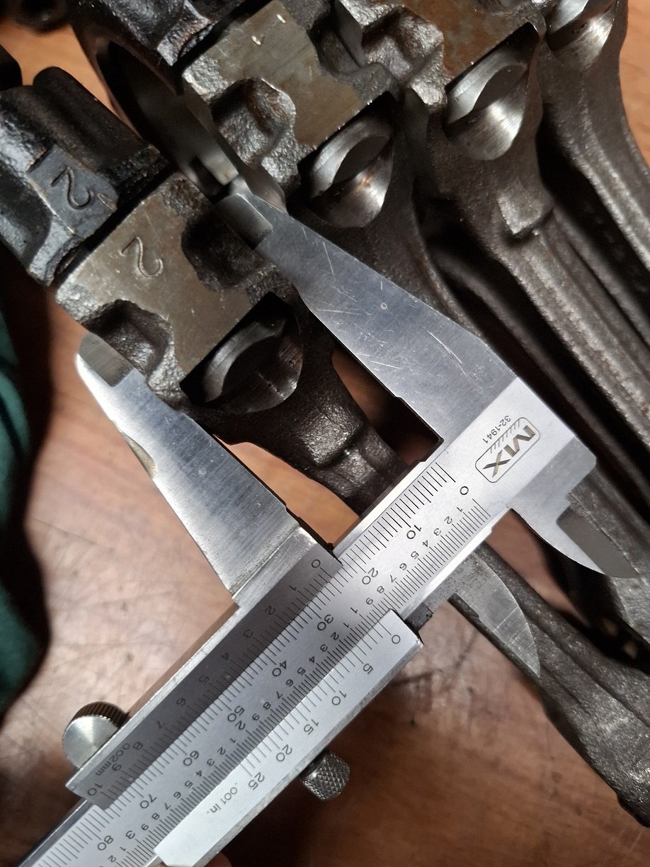
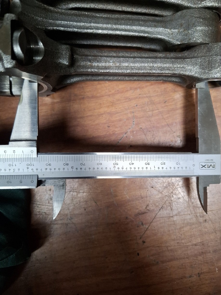
These are pictures.

-
2
-
-
- Popular Post
- Popular Post
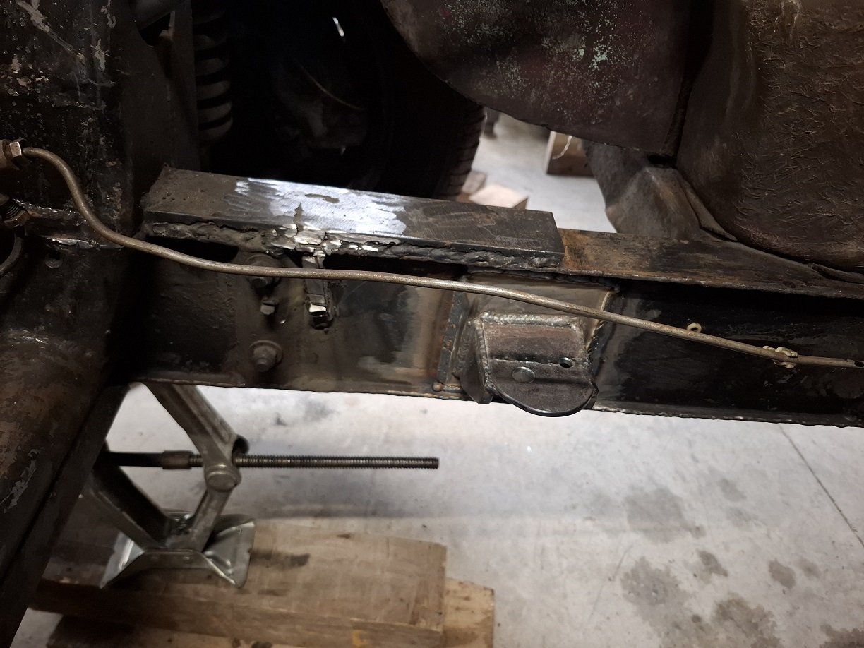
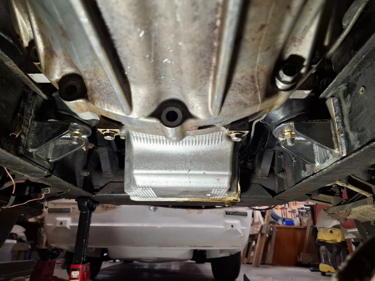
Got some more gas for the welder and finished off welding on the reinforcing plates.
Not sure of the easiest way to remove the gussets from the old engine mounts, I can't get in any closer with the grinder without cutting stuff I want to keep.
I'm not even going to try remove the giant 10mm flatbar @dmulally welded to the top of the chassis rail. I think, I'd regret it if I tried.
-
10
-
 4
4
-
8 hours ago, anglia4 said:
What was the failure?
I had been planning to build one.
Either I messed up when I capacity and self discharge tested my used cells, or I overheated them when soldering the BMS cables onto the nickel strips. I suspect the latter. After assembly some of the packs in the battery weren't taking a charge so the BMS balanced all the packs down to the voltage of the lowest one.
If you use a cheap nickel strip spot welder, I found it would only work using a car battery, I got nowhere using a Lipo. And the mosfets on the 'welder' get real hot, real fast so you can only do a couple spots then let them cool or the smoke escapes. I'd recommend buying more than one of them. Maybe you could try mount a big heat sink to them, that should help.-
1
-
-
1 hour ago, davidian said:
where do people get their batteries from? Im looking for a 48V jobbie, doesn't have to have massive capacity but needs to be able to push 2000W along if possible.
I got mine from AliExpress after my attempt to build my own using second hand cells was a bit of a failure.
Still not cheap. 52 volt 14.4Ah
https://unitpackpower.aliexpress.com/store/1178407?spm=a2g0o.order_list.order_list_main.7.a2511802cOA7S0
On my e-BMX I got about 40km of 38kph before my arse was too sore and I was too frozen. Said it was at 50%, so could possibly do 80km. Assume the cells are what they say they are. -
- Popular Post
- Popular Post
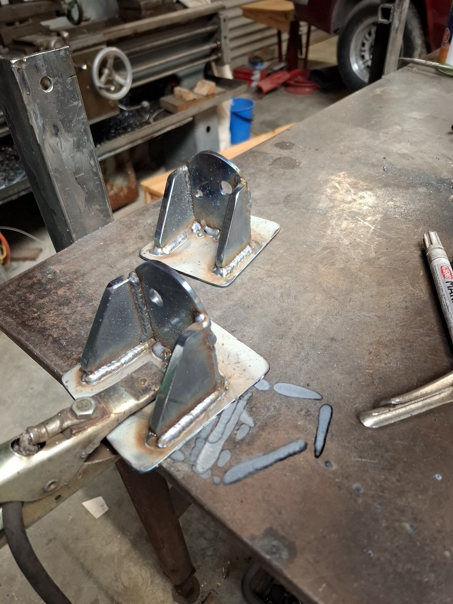
Got some factory engine mount rubbers and made some mounts.
I'll weld the top and bottom of the reinforcing plates next time the engine is out.
-
14
-
So the Bosch is actually a walbro.
The pumps are still fucked though. I could not revive them on the bench. The Carter is not drawing any current. I pulled the pump guts out and manually turned the motor. It turns but didn't spin freely, and no signs of life.The Walbro still draws current and gets warm, but no amount of banging on a hard surface would wake it up.
-
1
-
 4
4
-
-
3 hours ago, VitesseEFI said:
Well, this thread took a search…..
Bad news on the fuel system gumming up.
Assume the Bosch pump is one of the canned ones with the crimped end? assume it’s still drawing current, just not spinning?You could try taking it off, applying power and tapping on something solid. This seems to work better than just smacking it while on the car, though you could try that too. Don’t leave the power applied for more than a few seconds at a time and if it runs don’t run it dry.
If the above fails then you can try emptying out the old fuel and tipping a bit of fuel system cleaner or solvent of your choice in instead. This is a bit of a PITA as there’s a spring loaded NRV at the discharge end, so you have to shake it out of the suction end and tip solvent in the same way. Leave to soak and repeat power/tap process. I’ve saved a couple like this.
If you are keen and careful it’s even possible to uncrimp the end, extract the workings, clean, free off and reassemble. I’ve done 2. Both worked after, but one had a weep that was a bit much to use, so bit of a desperate measure. I had more time than money at the time and a pile of stuck pumps.
Good luck….
I got as far as smacking it in the car while applying power. Might have time today to pull the pumps... got to do all the xmas shopping today though.
-
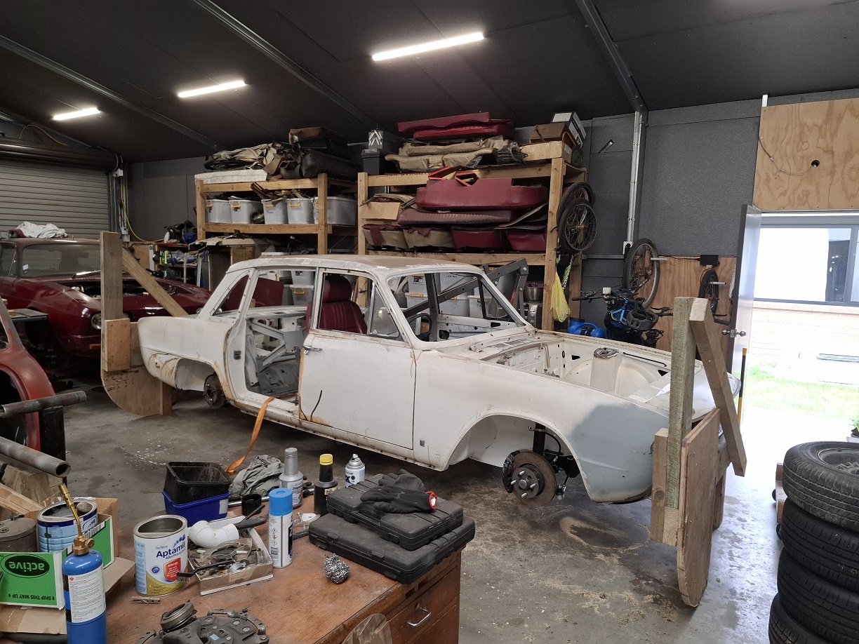
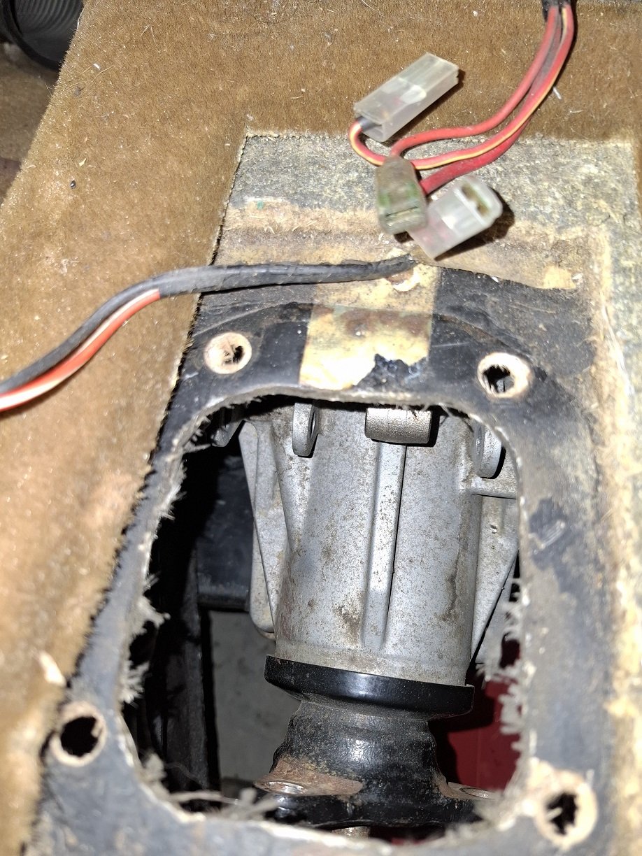
So this has been living in the side shed for a while so I can do stuff to the Scimitar. I'd been starting it occasionally.
A few months back it suddenly wouldn't idle or rev and couldn't keep it runnings.
Well shit. Injectors must be gummed up?
Several months later, last weekend, I finally got around to taking the injectors out.
I put them in a jar of mineral turps cause it seems to be a pretty good solvent. Then I put that jar in the ultrasonic cleaner, for 30 minutes. I did that a few times, they probably had about 2 hours total.
Today I put the injectors back in the car and reconnect everything. Fetched the battery and installed it.
Turn the ignition on.... wait... where's the fuel pump prime. Turn the ignition off and on again but still no noise from the lift pump or high pressure pump.
Have a look at those, the wiring to them feels a bit warm. Maybe the earth has corroded?
Go get the jumper cables and connect the pumps directly to the battery.
Nothing.
Well, fuck.
BOTH pumps are gummed up with old gas?
The low pressure Carter looks like it might come apart, maybe.
But the Bosch, I assume I just have to fork out for a new one?
-
2
-
4
-
-
22 hours ago, rotormotor said:
Low 'rolla
SNAP!
-
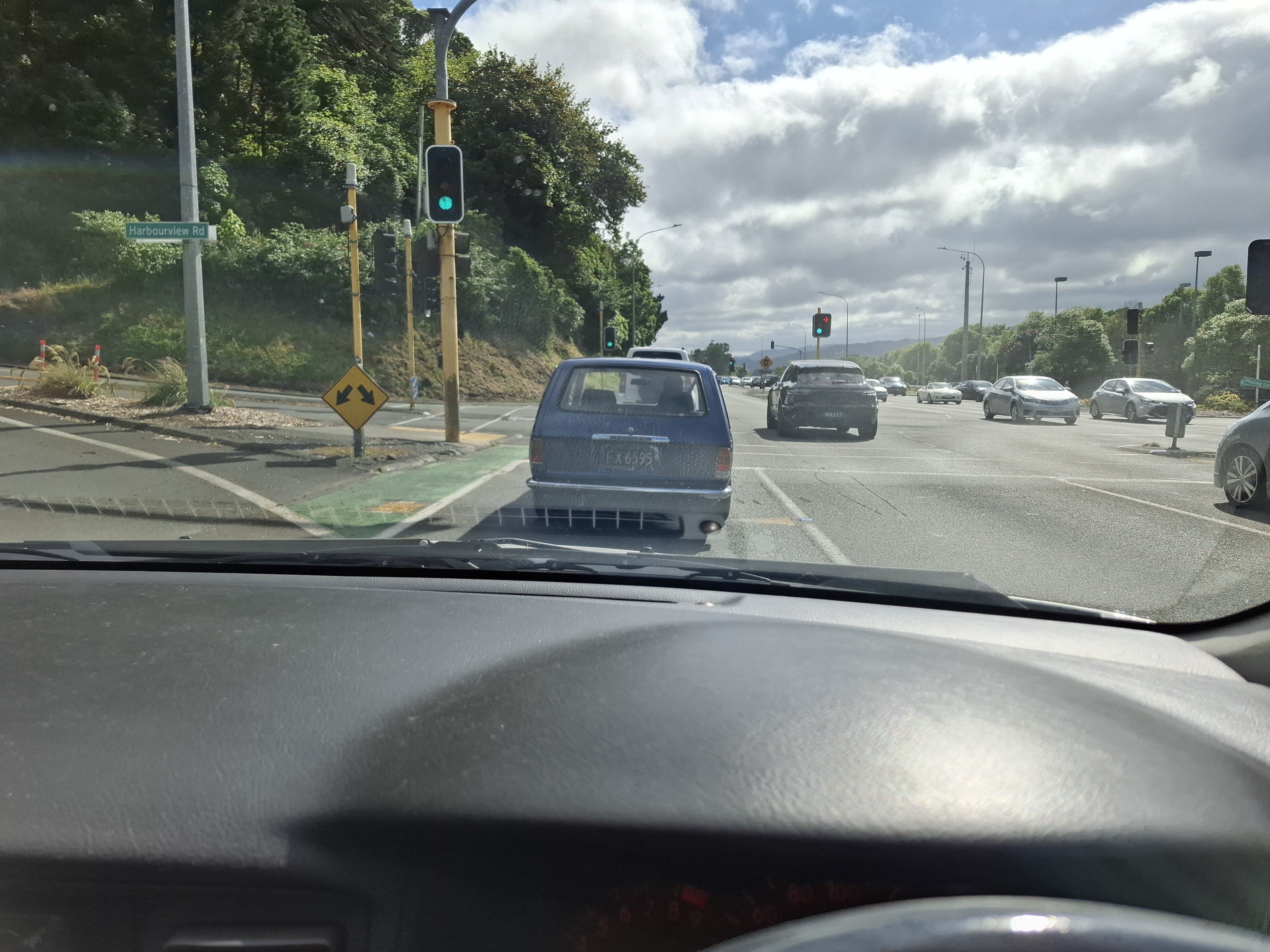
Saw this guy heading past lower Hutt this morning.
One of us?
-
2
-
-
2 hours ago, Slowhoon said:
NZ saloons got both single circuit and dual circuit brakes as standard during their production life. I have wondered if the dual circuit master cylinder option originated from Australia.
So does the car have single or dual? Spares for the latter have been hard to get in the last couple of years.
It's the later tandem master cylinder(though this car did originally have a single circuit). As far as I know, the same tandem master is on the Stag(dunno if all of them had it). Internet says Stag is larger bore. Rimmers or Chris Witor in UK have the kits for the tandem, so that's a last resort.
I'll stop in at MP Autoparts on my way home and see if Greg has anything. -
3 hours ago, BiTurbo228 said:
Not sure what your engineering stuff would say about it, but I've made a twin master setup to work with mine. Cut out the middleman of a pendulum box and just made a plate that bolts to the bulkhead:
A T2000 might be on the upper limit of what I'd want to drive on the street with manual brakes, but hopefully it'll be fine!
Yes, I could do something like that. I'd prefer to stay with the regular master cylinder and put in an adjustable pressure reducing valve to fix any balance issues. Just because it's simpler.
-
1
-
-
Noticed the master cylinder is leaking a little out the back. I thought I put a seal kit in it, but I guess that was 7+ years ago and it's just been sitting in a box since then.
Hawkswood have no stock. I wonder if BNT will have anything...
It's usable for now, the brakes just need to work enough to tow it 6 minutes up the road to visit the alignment machine. But that likely won't happen this year.-
2
-
-
- Popular Post
- Popular Post
Brakes bled on my lunch break, with some bottles of random DOT4. Both rear banjo bolts were only finger tight. And one of the lines at the rear t-piece needed tightening and loosening a few times before it stopped leaking under pressure. After bleeding, I held down the pedal hard as I could for about 30 seconds, still dry at all the joins.
NFI what the brake balance is like.
Handbrake works.Guess the next thing is to put the wheels on and take it off the tip-over jig. Then enquire at my local garage if I can put it on their wheel alignment machine to see if the subframe is anywhere near straight. It's Julian Cheers old place, he said there is an alignment machine.
-
10
-
- Popular Post
- Popular Post
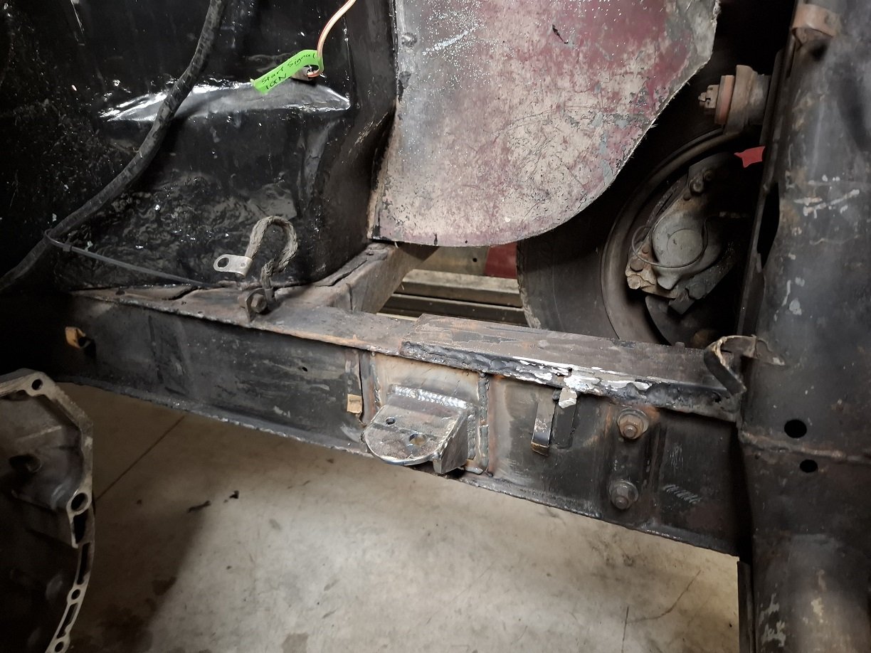
Reinstalled the underbits and put it back down.
Now I can test the lines for the rear brakes.
And need to make mounts for the passenger seat.
It could then go on a wheel alignment machine to see if the subframe is mounted straight.
Then put it back up. Take everything back off. Weld the subframe mounting studs so they can't move. Finish the welding on the underside of the passenger seat mount. Seam seal. Then some kind of top coat. Put all the bits back on. Put it back down. etc... etc..-
14
-
- Popular Post
- Popular Post
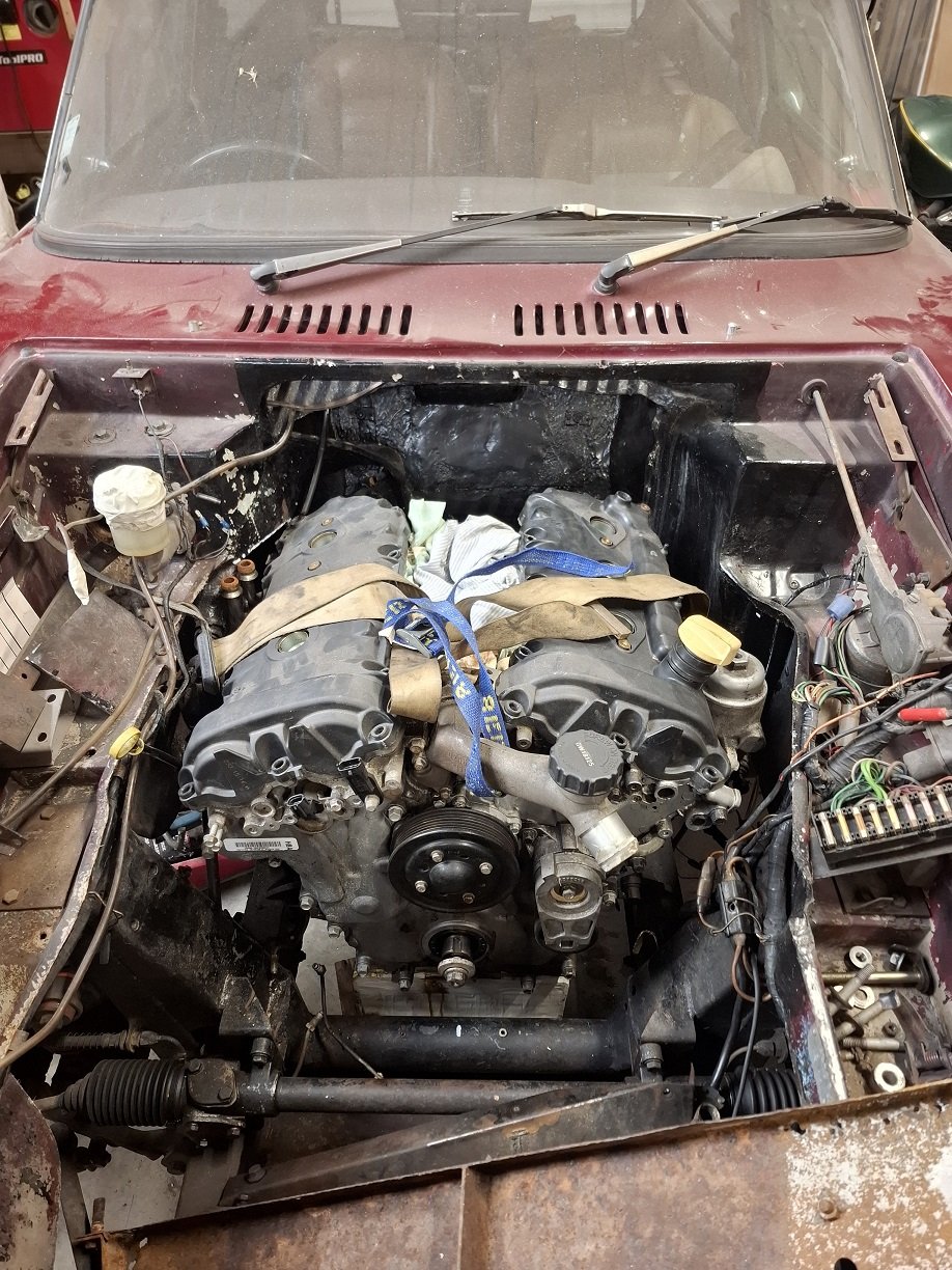
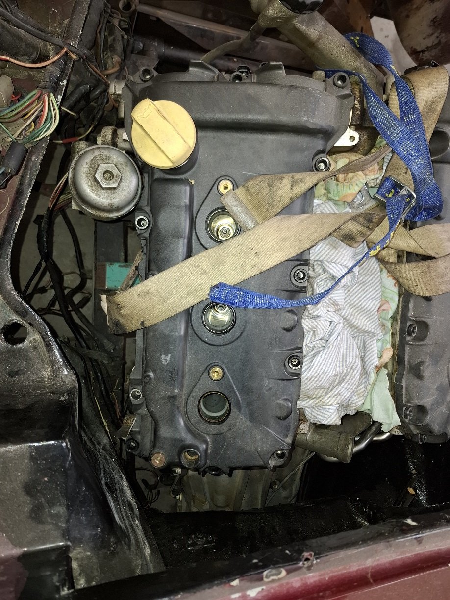
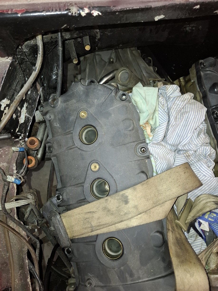
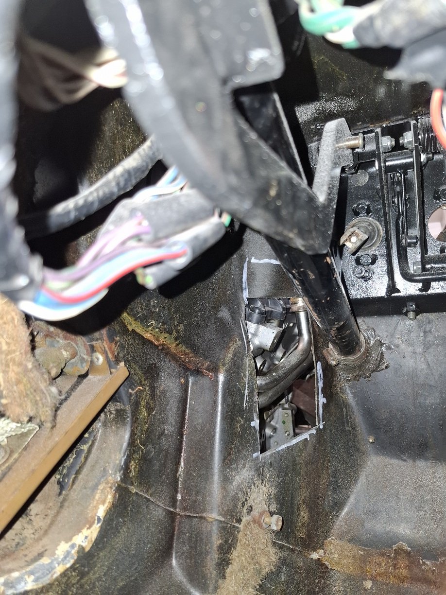
Spent some time getting the engine where it needed to be. Back corner of one head wanted to be in the same place as the footwell/bulkhead.
The small amount of intrusion.
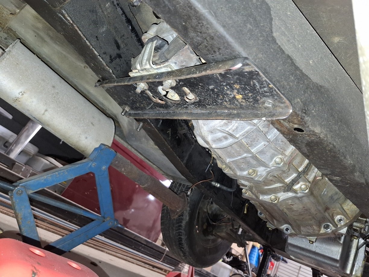
Flipped the gearbox xmember backwards and it got close enough to work with a couple extra holes.
I'll modify it a bit more to lift the box a little. As well as needing extra captive nuts in the chassis.
Gear linkage didn't come with the box, they sell it separately, it also sits way too far back, so I need to make one. Or maybe adapt one from a K11 for the lolz
-
18
-
- Popular Post
- Popular Post
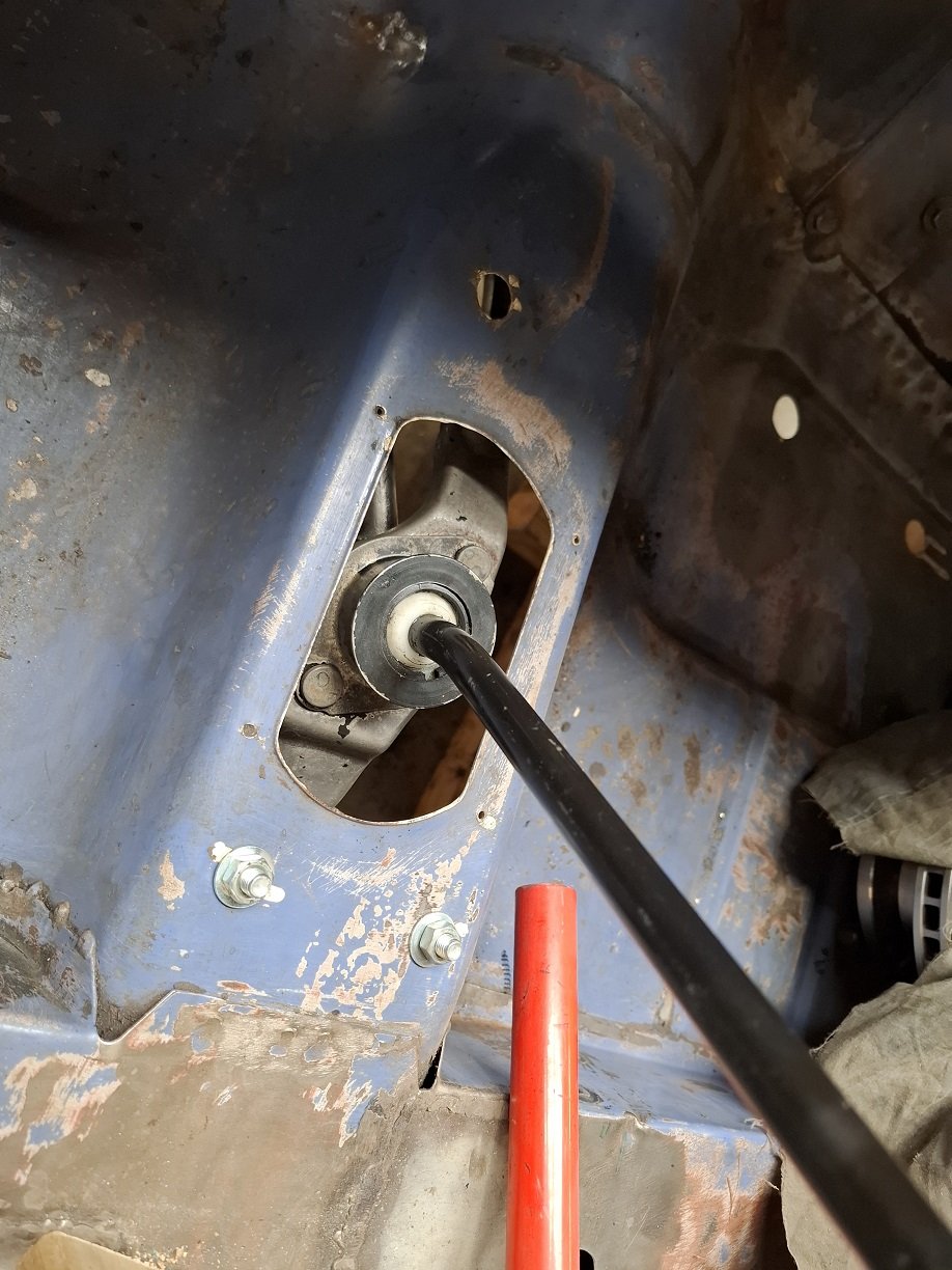
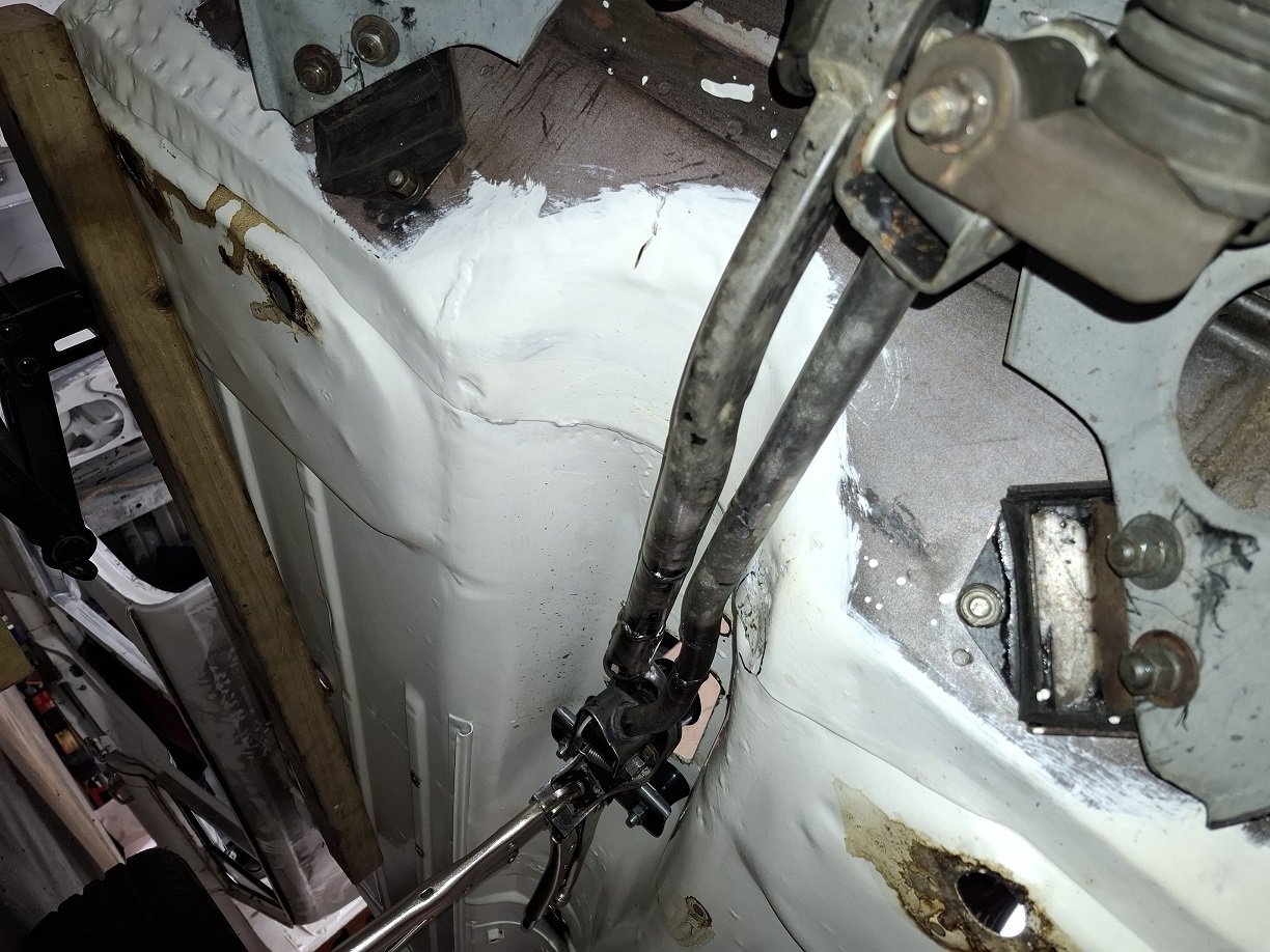
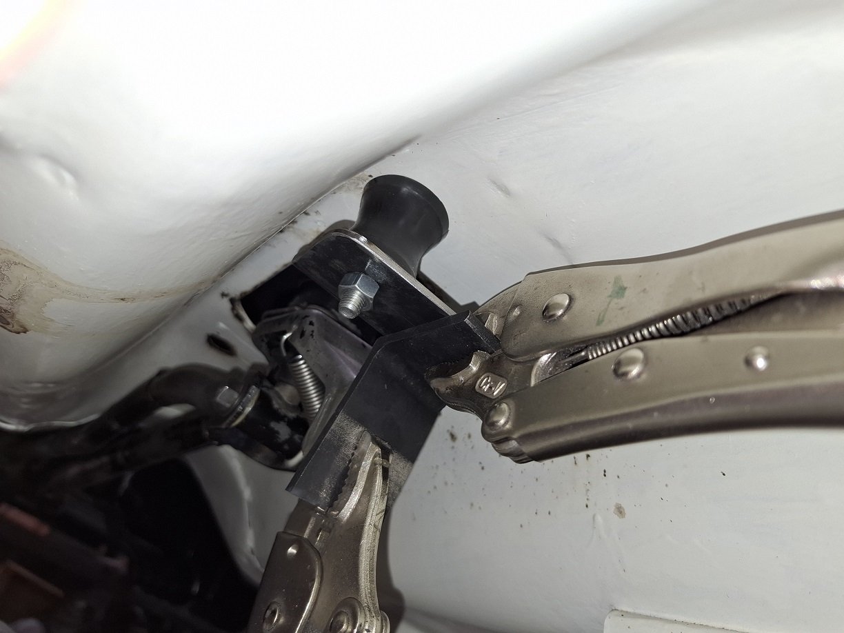
Gear wobbler installed. I can get all gears.
The rods needed to be shortened. And a small area of the tunnel needed to be massaged in by 5mm for clearance.
The nissan rear rubber was very soft so the gear change was not great. I got some urethane mounts intended for an original mini linkage and have mocked up a bracket. MUCH better now.
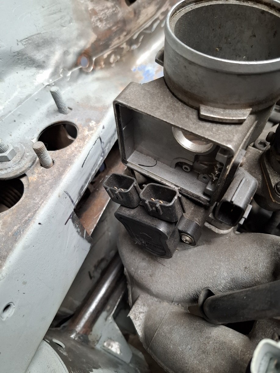
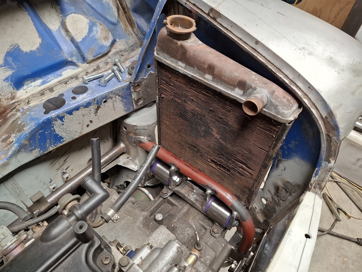
Made some clearance for the back of the intake plenum. It won't get in the way of the brake and clutch mechanisms.
A factory radiator "fits". I think I will cut out the inner wing on this side too, so it fits a bit better. The bottom pipe will need to be in the middle to go between the mounts.
-
13
-
- Popular Post
- Popular Post
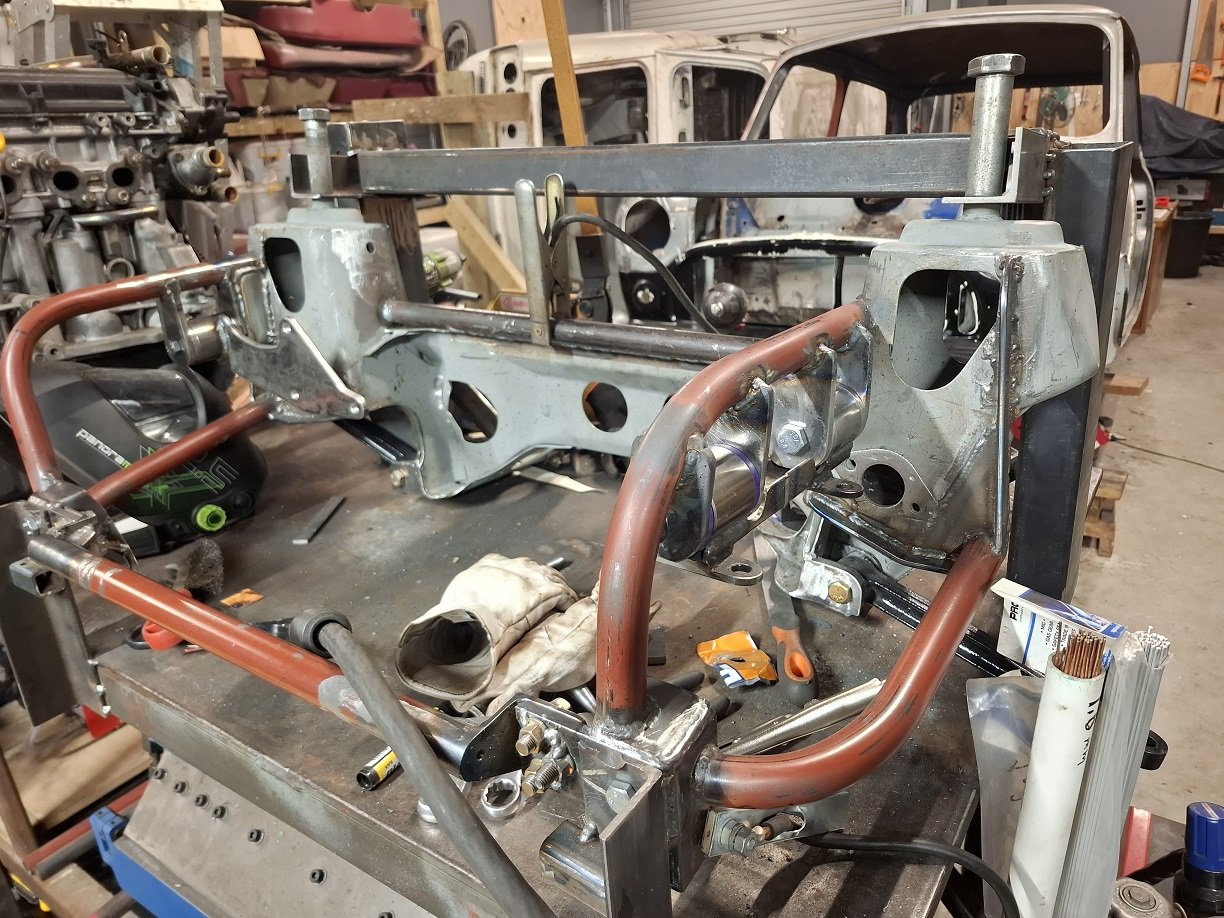
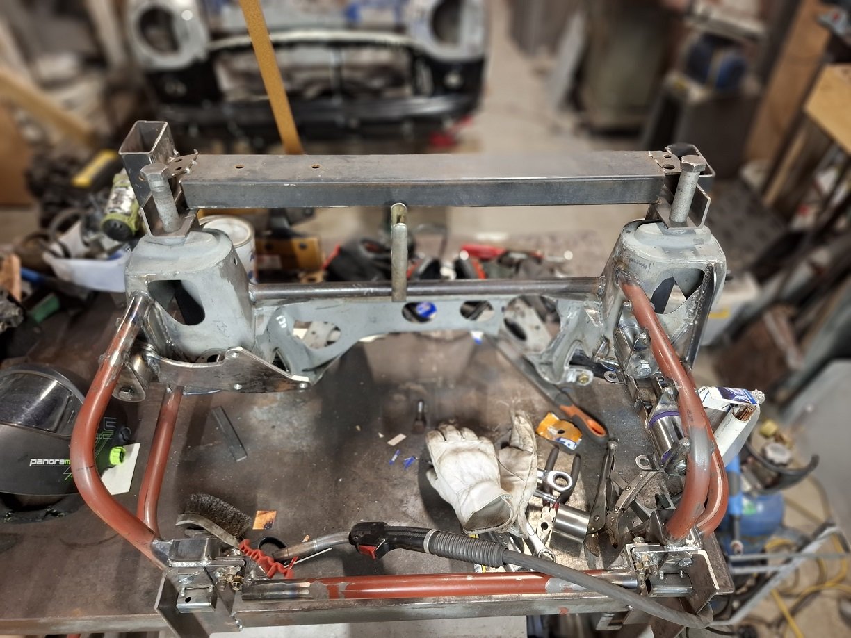
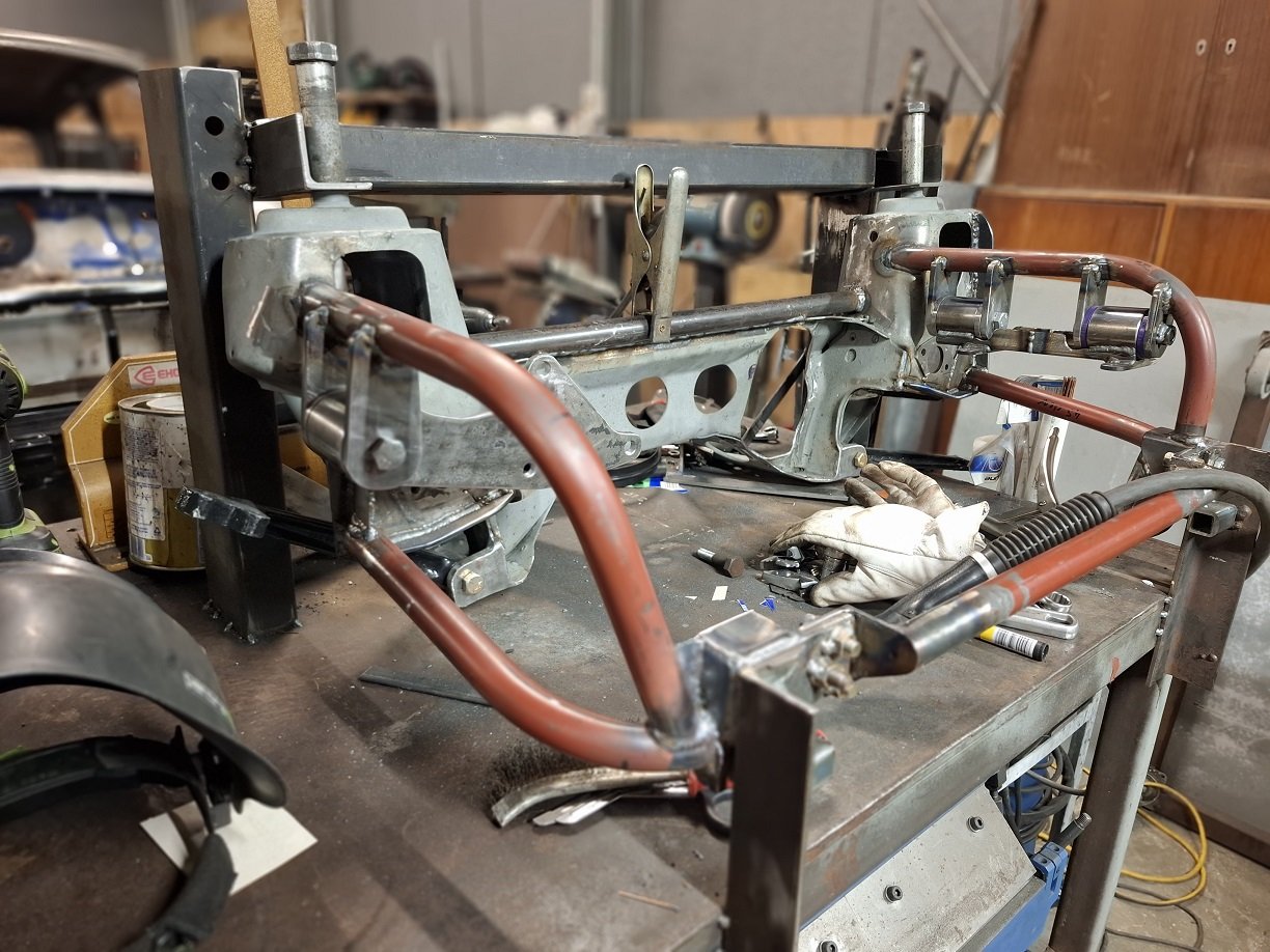
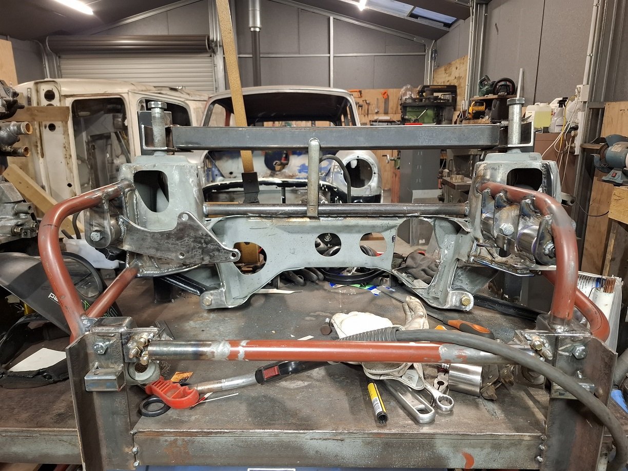
Subframe getting there. Engine moved a bit over to the passenger side for tie rod clearance.
I had to rework the gearbox mount because I initially did it without shims and it was WAY TOO tight.
I'm trying to find somewhere to add more bracing to the front tierod mounts since I've had to trim them a bit.-
18


For Questions Regarding WOFs/CERTs/NUMBER PLATEs
in Tech Talk
Posted
Can I use this hose?
https://1stparts.co.nz/product/aeroflow-push-lock-500-black-series-hose-5-per-metre-5-16-new-fuel-safe-and-petroleum-oils-charged-per-metre-not-submersible/
It has the pressure rating and "Fuel/Oil" written on it.
Or does it specifically have to say SAEJ30R9 for the WOF man to be happy?