ProZac
-
Posts
1,255 -
Joined
-
Last visited
Content Type
Forums
Downloads
Events
Gallery
Everything posted by ProZac
-
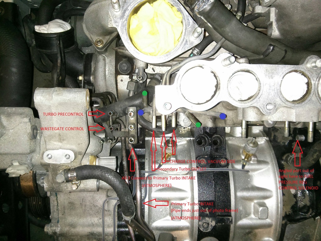
Some of what I put up here will just be reference for me, so when it's back together, and has issues, I can look through and hopefully find the cockup . Fuel Vent Plumbing: As far as I've gotten tonight with the on-car side of the vacuum plumbing: Dinner time now, so an end to the fun for the day.

-
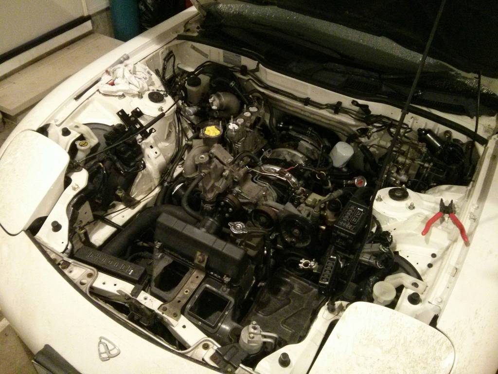
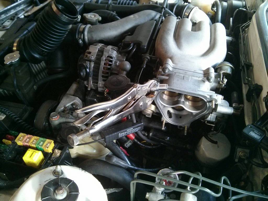
Got a couple of hours this afternoon, so started reassembly. Got the injectors all cleaned up, new filters and o-rings on and put back into the rails. Gave a few other things a quick clean and removed a bit more stuff (counter-intuitive, I know) to make more room. Figuring out the solenoid block was the majority of the battle for the vacuum system, but I still have to map out where all the steel hard vacuum lines go so I can make use of them correctly and keep it all tidy. Not overly hard, just time consuming. I'm also testing all the sensors and actuators against the factory specs during reassembly. It would suck to get it all back together and then find something that should have been fixed while it was apart. I've gone as far as I can today (all the fuel evap system is tested and plumbed). I loaned my vacuum brake bleeding kit to Dad, so I can't test anything further. I'll be doing some tuning in at uni tonight, so I'll borrow the mighty-vac they have there, as it can apply pressure too, so I'll be able to fully test everything . Bullshit update? Yeah, kinda. Pic of what the engine-bay currently looks like:
-
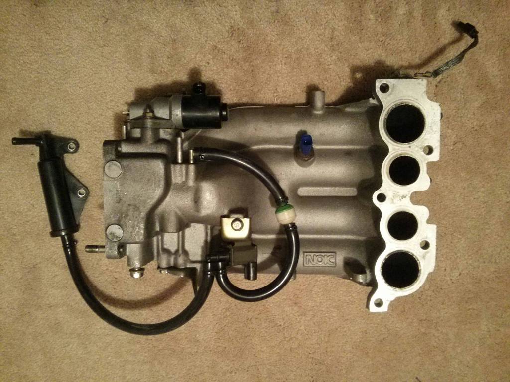
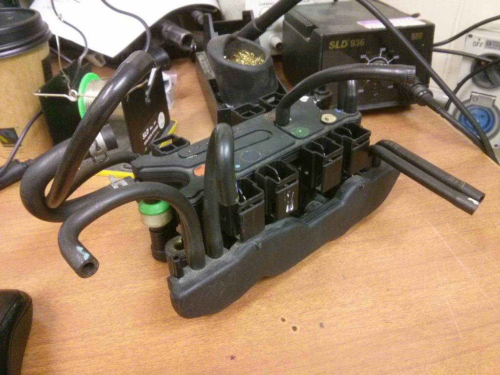
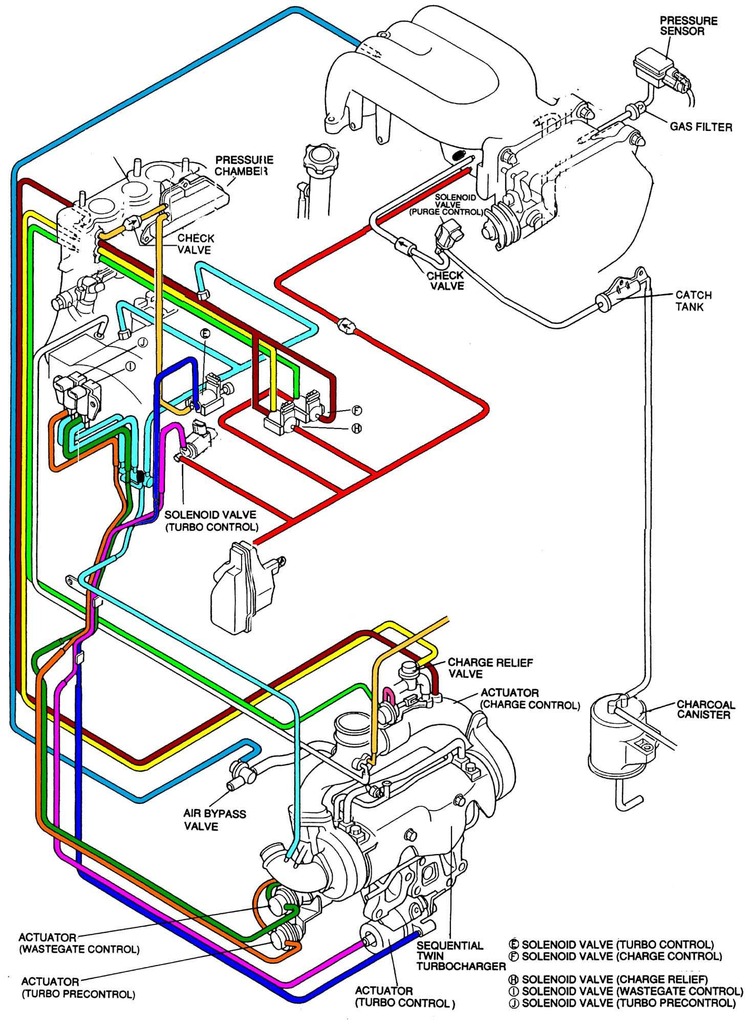
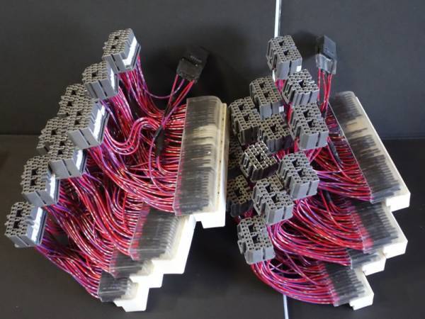
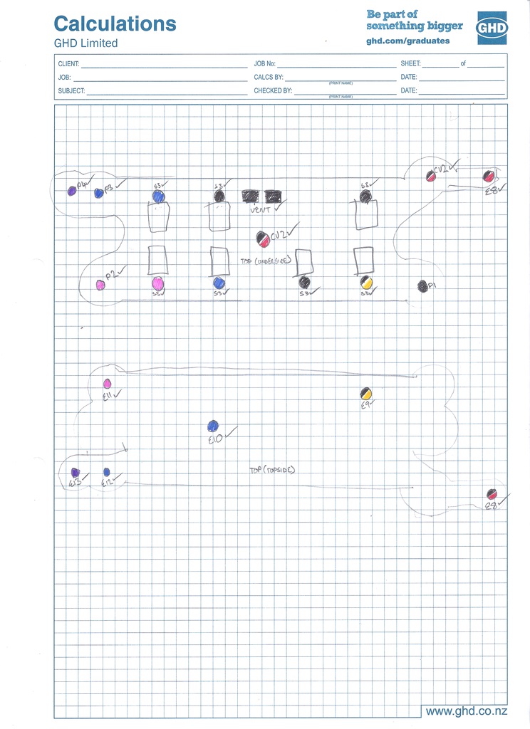
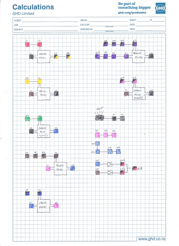
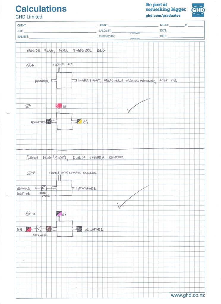
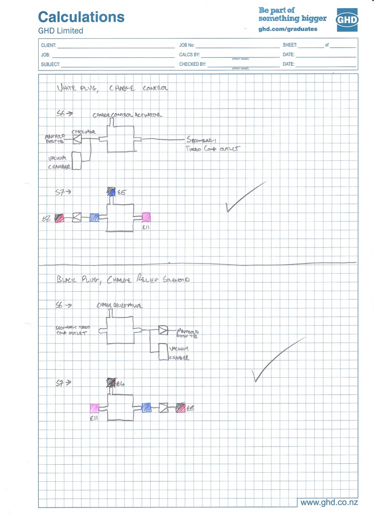
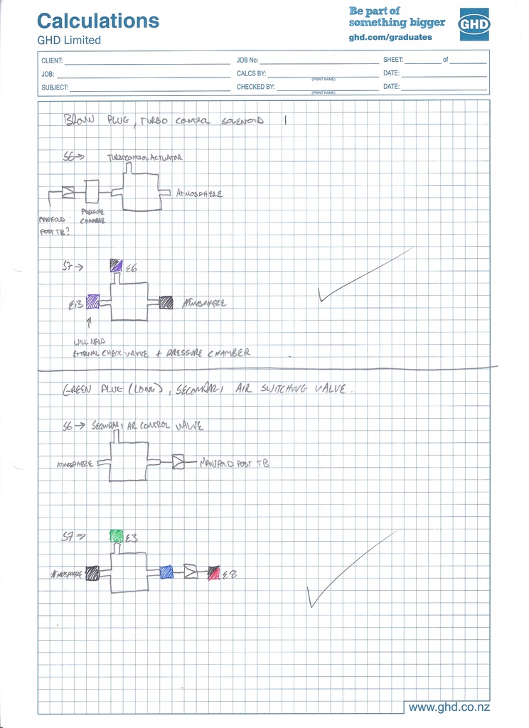
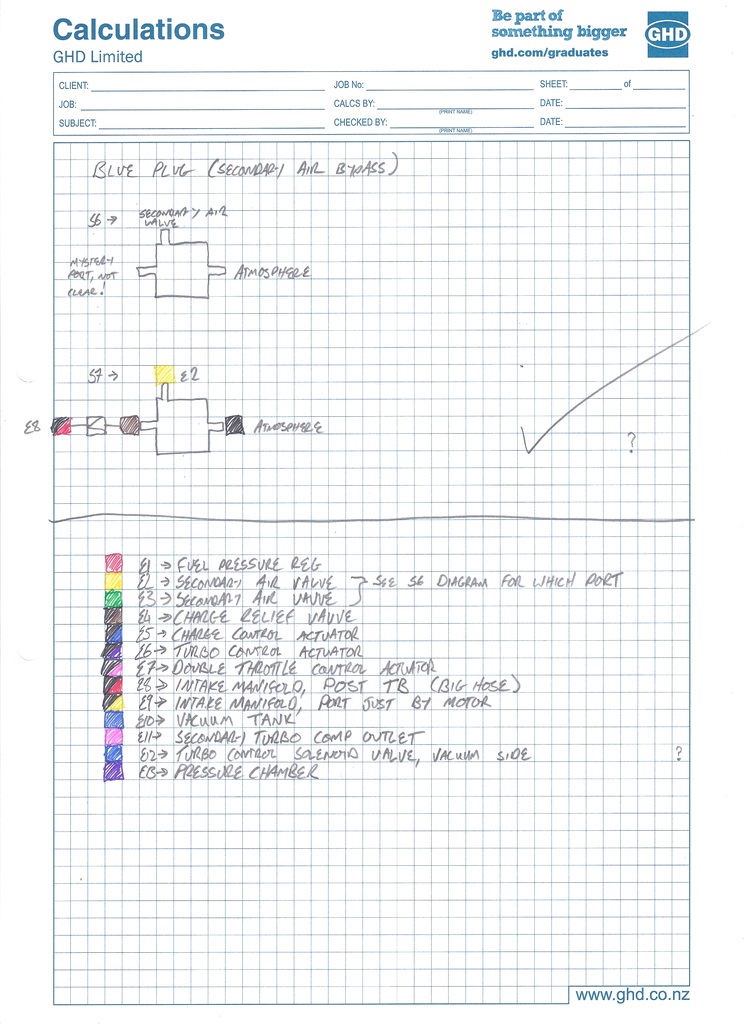
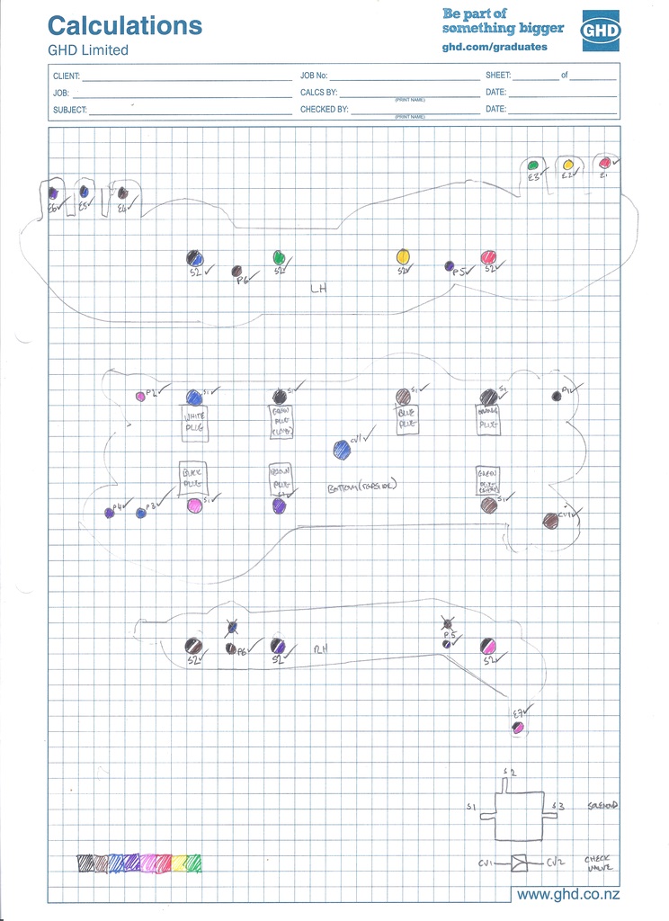
Just a warning about this update, It contains much, much tedium, but also a pretty decent level of winning. Also, no, I don't work at GHD, it was just a pad I found floating around at Uni. With removing the upper intake manifold, I also removed the vacuum block. Anyone that's had anything to do with the vacuum systems on FD RX7's before is bound to tell you horror stories. They certainly are relatively complicated compared to other vehicles. There is some pretty good information available on how the systems work for a Series 6, as they were released in the US, and the USDM service manuals are easy to find. This generation has what's called the 'rats-nest', which is a rack of three way solenoid valves, all connected to various actuators and sources via individual vacuum tubes and a manifold of metal tubes, see exhibit A: Apparently this system, after removal of all emissions related malarkey, can be reduced down to this: Wow, that looks a whole heap better. Still not great, but certainly better. I should do that, right? One catch. On the Series 7 and above, the 'rats-nest' rack of solenoids was replaced by a much more aesthetically pleasing integrated plastic manifold design: As the Series 7 and up RX7's were never sold in the US, I haven't been able to find any FSM data on this update. In fact, finding ANY info on it whatsoever seems to be pretty tricky. This makes it a bit hard to figure out what to put where to simplify it, or indeed check it's correct in the first place! The series 7 update also included an ECU update to 16bit processors, and a change in header plug design. Now, because I'm an internet weapon (this is not true), I've been browsing Yahoo Japan a bit looking for interesting FD parts and gathering info. I stumbled across these: Harnesses for plugging a 16bit ecu into an earlier 8bit car. Iiiiiiiiiiiiiiiinteresting. To my mind, this means that the vacuum systems must be functionally the same (or at least very very similar). Excellent, so hopefully this means that I can relate the available Series 6 data to the Series 7 unit, get money, power and bitches (in that order). I need more info on the integrated vacuum manifold. Luckily, I happen to have one, HUZZAH! EURON8 is a bloody good bugger, and sent me some pics detailing how they come apart, and it really is easy to pop them open. There are a couple of valves missing from that photo. That is actually a second hand unit I bought from trademe as it had a broken nipple on the plastic manifold, so was pretty much useless except for parts. With a bit of tubing, and a bit of time, I mapped out where all the passages go, which gave me this: And this: And this: And all of these: I was able to match up what each solenoid valve in the block did by looking at what colour plug went to it, and tracing this wire back to the ECU header plug, as the pinout for that (which is an internet resource, not from a FSM, but seems to be holding up reliably) tells you what's up. I was then able to compare the vacuum routing of the corresponding valve on the Series 6 FSM info, and determine if it would work the same in the Series 7 manifold black, and where to hook lines too, etc. A couple of tricky spots though, the Series 6 has a few more valves than the 7, and figuring out what they kept, and what they got rid of took a bit of noodling. The Series 7 has no EGR, so I knew this valve wasn't going to be in the manifold, it turns out they moved the Charge Relief valve, which was mounted external to the 'rats-nest' on the Series 6, into the manifold in the Series 7. Other differences from the USDM Series 6 spec are the lack of a Port Air Bypass Valve and Split Air Bypass Valve. Wicked, more valves to not worry about. I also noticed that the wiring colours from the USDM Series 6 manual match up to the JDM Series 7 I have, as long as you look at it logically and don't take anything verbatim. I was thrown by there only being one output wire from the ECU for two valves, both called 'Turbo Control'. One of these valves is fed pressure, and one is fed vacuum (both from tanks, via check valves, so both conditions can exist at the same time). The valves apply pressure and vacuum to either side of the turbo control actuator diaphragm, giving it more grunt without having to increase it's area. Cool. Two of the valves in the manifold block on my car were stuffed, and these matched up to the error codes the ECU was throwing. Good to know that error reporting system works. So, that's allowed me to map out how the vacuum block works, and where to connect each of the 'E' (External) ports on it too, and hopefully get the system working at some stage in the none too distant future . I'll try and get it up and running as it is, without removing any of the emissions gear, If I strike any issues I'll look at simplifying the system. I might tidy up all the info at some stage, as It could help out anyone else with a mis-behaving series 7 or 8, but that can wait till my car is back together .
- 269 replies
-
- 11
-

-
So. Much. Yes. I'll pm you my email address. Chur!
-
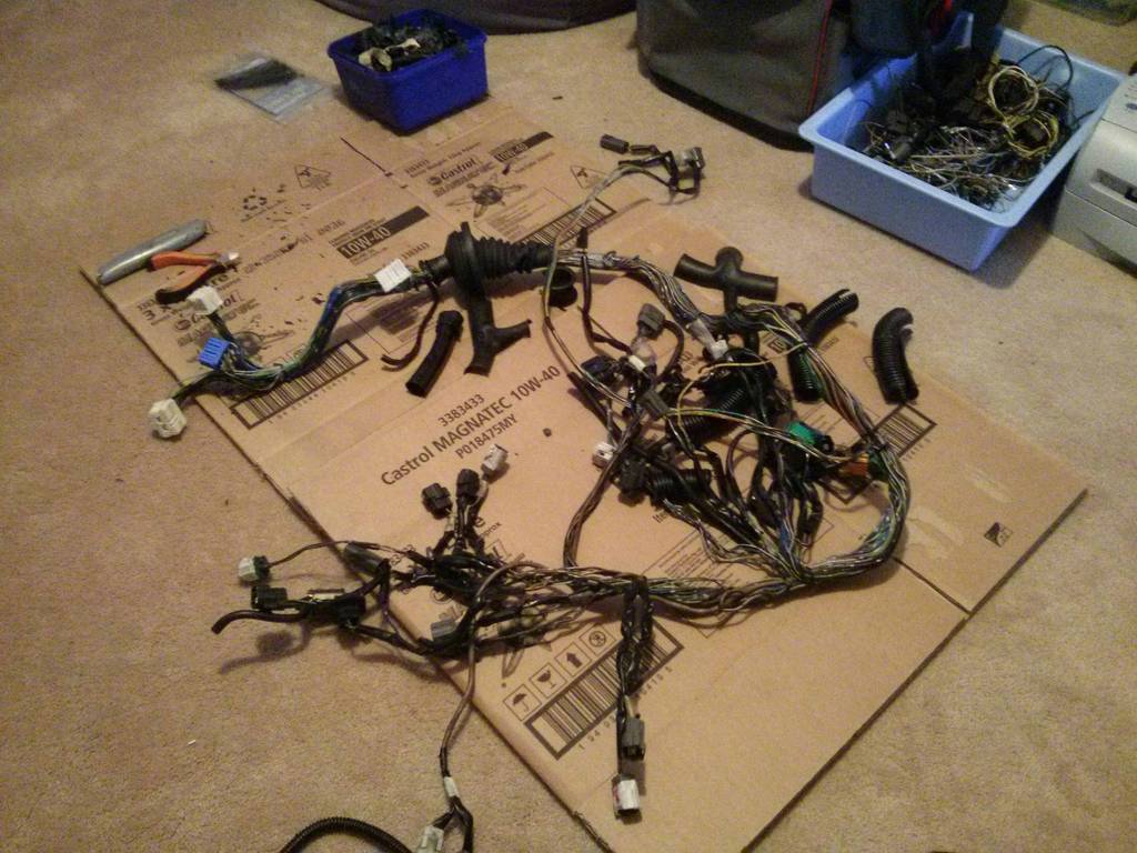
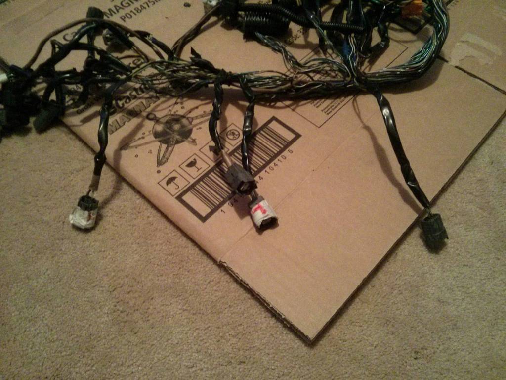
Got the loom out last night, while procrastinating about writing this report. I also did the dishes, two loads of laundry, and vacuumed. I'm sure any other students out there can relate. The covering was in a real state, super brittle and cracked, oil soaked and pretty stuffed. The actual loom itself underneath isn't in bad shape though, and will repair up nicely. Looks like quite a mess eh? It's not actually that bad, pretty simple as far as modernish looms go really. I also found something... Those are the four injector plugs, from right to left being Front Secondary, Front Primary, Rear Primary and Rear Secondary. I've confirmed this by matching the wiring colours, and toning the wires back to the ECU plug. I'm sure that when I pulled them off, the two with tape on them were on secondary injectors. Thus the two without tape were on the primary injectors, meaning the Rear Secondary injector was being fired instead of the Rear Primary, it supplies almost twice as much fuel, so it was never going to run right. It's possible the two with the tape were on the Primary injectors, not the secondaries I'm not 100% sure which way around it was, but they were definitely a pair, this would give the same result, but on the front rotor. ? I won the auction on a series 7 solenoid block, will grab it this week and try to get it apart without fucking it. Will tone out the rest of the loom too and figure out which solenoid is which . Now I might have to actually continue on with this report. Stink.
-
Chur . It's all the same stuff though, just what we're all used to we find easier. Thing about electrons is that you can't see em, so you have to have some tools that you trust to tell you what's going where, but it's just a different way of getting the job done .
-
Yeah, just the bits I've mentioned above for the moment. None of it can hurt, hopefully I'll find something interesting along the way. I think I've found the two dud control solenoids which are throwing codes. I'm pretty sure they wouldn't have been causing any of the problems with idling and fuel usage, but they need to be fixed nonetheless. There are two valves in the black solenoid box (only on series 7 and 8's) that measure open circuit, and do nothing when given 12v. This black solenoid manifold/rack thing actually looks like it comes apart, but suspect I'll have to make up some sort of tool/jig to sort it. The individual valves within all look like they're the same part. I've bid on another one from trademe with an eye to opening it up and hoping it has at least two good solenoids in it. Should learn how to open them, and get some spares, without fucking the original one from the car. Maybe I should recondition a bunch, make up an adaptor harness and sell them to the yanks for a massive profit? hah. Back to uni tomorrow, more work on FSAE car, and I have a report to write also, so will have to halt the fun for a few days . Alex, sort me some carbs? .
-
Puddles - Yeah, I was looking at the air pump system and wondering if it could be removed. The Cat.Converter is still there, I could maybe remove that at the same time if there is an easily purchasable solution... But I'm not sure about warrants if I do that? Plus, you know, I'm a little older and actually slightly care about the environment... I could probably justify hollowing it out to myself by saying that I'm not using the car as a daily anyway... I had also wondered about how to run the drive belt afterwards. I'll ask Aunty Google and see what pops up. The Cat.Converter needs the air pump to operate correctly doesn't it? Because of the type of Cat. It is? Downtrail - Oh how I hope you prove to be correct! All four hoses on the two turbo control valves were cracked wide open, can't have been a good thing.
-
I'm trying to develop a plan here. Unfortunately even with how far I've torn into things today, there hasn't been a 'smoking gun' as to what is really wrong. I'm left with putting it back together, and hoping for the best. It's logical to perform a few fixes along the way though, I think. The loom is in pretty average shape, and Puddles is right, it doesn't look too hard to remove from the vehicle. I'll do this, inspect it, repair a few sections that look a bit abused and tone it out too. I need to gather a bit of into on the series 7's, as there really doesn't seem to be a huge amount floating around. There were plenty of cracked vacuum hoses in the turbo control system, so I'll replace all those too while I'm at it. Toning out the loom will let me create a map of what the solenoids in the 'black box' actually do, as I haven't been able to find a clear picture anywhere. I suspect the system is the same in operation to the earlier 'rats nest' models, but just with a pretty plastic manifold. If I can relate the two, I should be able to troubleshoot it more effectively. I've got those two error codes still showing up in the ECU, so I can investigate those at the same time. Summary of shit I'll be working on: Injector seals replaced, possibly have the injectors re-tested depending on cost / finding a sweet hookup. Loom out, stripped, repaired, recovered. Vacuum hoses replaced. All solenoids / sensors tested against factory specs. All along the way creating a better knowledge base of the series 7 stuff, so hopefully someone else can find it helpful in the future. There is to be none of the 'while I'm in there I could upgrade this...' performance bullshit... That road will lead to disaster. You'll all keep me honest right? My M.O. previously has been to tear shit apart, make it too big of a project, give up. Really need to not do that.
-
UIM is off, injectors are out. They show no overt signs of any leakage, which is disappointing, but doesn't rule anything out. I'll put new seals on them anyway, and maybe have them test again while they're out, because its a bit of a bitch of a job to do! Found plenty of stuffed, cracked and broken vacuum hoses, which is apparently pretty common. Took lots of pics of how it all came apart, and pretty much everything was already marked. Will replace all the hoses one by one I think.
-
Yeah dude, #rotanglyfe? Checking timing, without fucking a brand new set of plugs: Seemed spot on, white mark on tone wheel lined up with the notch on the front where the FSM says it should, so that's confirmed as being good. Going to take the upper intake manifold off now, and have a look at the injectors. Most of my tests seems to be pointing towards them having some sort of sealing issue. The fun continues!
-
I pulled the main EGI relay and got Laura to crank the engine over, and plenty of vapour seemed to to come out of the spark plug holes. That certainly points towards fuel leaking past the injectors. So tired though, will re-do that test tomorrow. Could possibly be oil from the oil injection system? It was quite a bit though... Hmmm. According to the USDM series 6 manual, the injectors are supplied power from the EGI relay, so that should have disabled them Bed time.
-
Oh, durhhh, I'm a bit of a tard tonight and wasnt working it out properly. Everything agrees that fuel pressure is around 40psi. Forgot sensors have a 0.5V offset.
-
Hmmmm, 150psi pressure sensor agrees with 100psi pressure sensor, 57psi. The mystery thickens. Super high fuel pressure, or super shitty sensors? I can see myself borrowing one of the expensive ones from uni tomorrow!
-
Slightly frustrating evening. Plugged in a pressure sensor to the fuel feed line, and got a reading of 57psi, which is far far too high. I double checked using a friends mechanical gauge, and it reads as 38psi, right on the money. I'll do some back to back testing tomorrow to figure out whats lying and whats true. Maybe those cheap ali-express sensors are crap... But I did test them on the fuel system on the racecar at uni, and they gave the same reading as the genuine Honeywell sensors there. However, intermittently the fuel pressure would drop immediately to zero when the fuel pump connector in the diagnostic port was removed, on both the sensor and the gauge. Most of the time it holds within a couple of PSI of pressure with the pump running though (whatever that pressure might be... I hate conflicting readings! If it wasn't too late to charge up my air compressor now I'd sort it) I'll try and find a reliable way to replicate this fault, as it points to a leak issue. Oooh, idea. I'll screw in the 150psi sensor I used for the compression test and see what that says. If I can get two out of three to agree that might help / frustrate me even more.
-
Bah, to hell with checking, I WOOHOO'd, and cut my best pelvic thrust dance moves in the middle of the street!
-
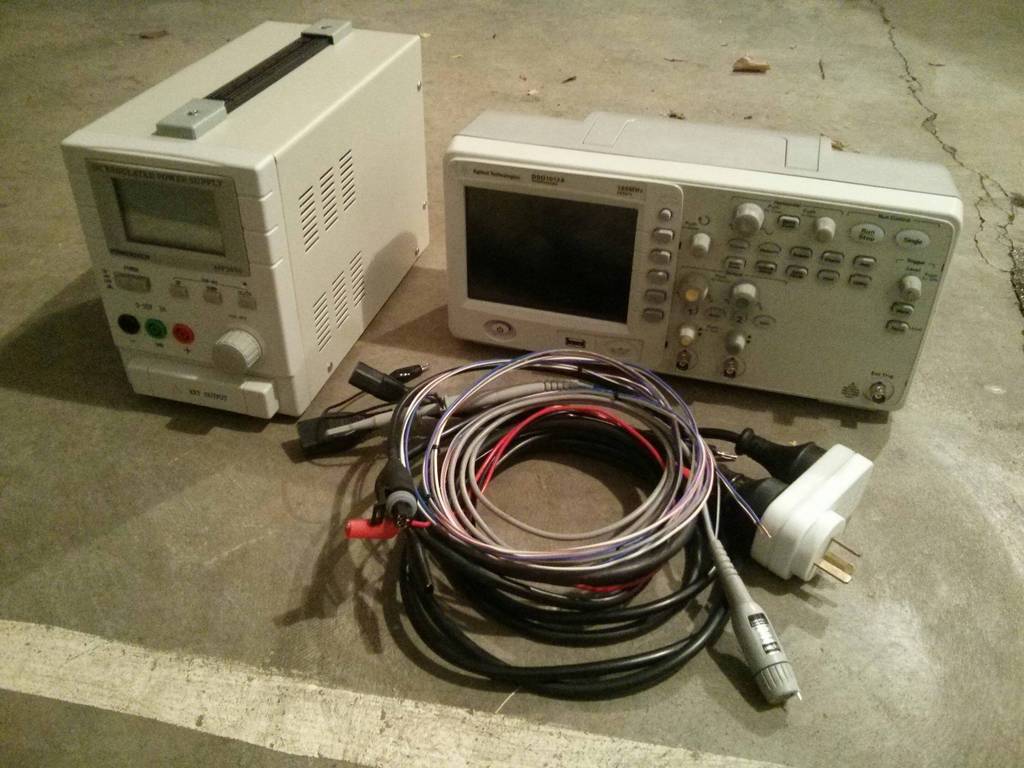
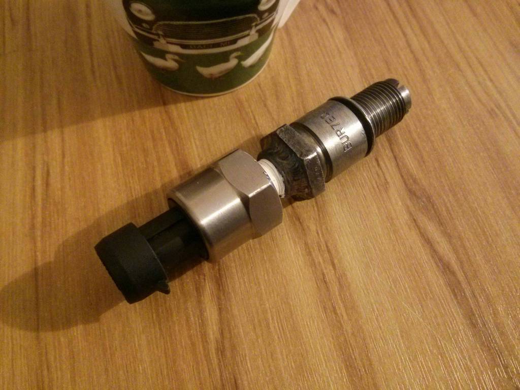
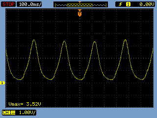
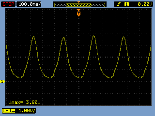
One rotary compression tester adapter: I cut away the crimp just above the sparkplug hex, and then tapped the porcelain out with a drift. Came out really easily. Spun up a bit of bar to sit in where the porcelain has been, tapped it for 1/8NPT, and welded it in place. Screwed the sensor in with some thread tape, and it's a good-un. The supporting gear needed to actually get anything useful out of the sensor: If I find time I'll make up a simple little box with a display to give the readings, but this lets me get on with fixing this car for the moment . Front rotor: Rear rotor: They look all good. The sensor measures 0-150PSI (not sure if gauge pressure, or absolute), outputting 0.5-4.5V. Working this back, the front rotor is showing ~130psi, and the rear rotor is showing ~140psi (subtract 15psi from each of these if it turns out the pressure sensor measures absolute pressure). The peak figures don'y really matter though, outside of the fact that they're all pretty even. I forgot to open the throttle when testing anyway, so they're not really accurate. What is good though, is that all the peaks are pretty even, meaning the motor seems to be sealing well. Fuel pressure testing next! [EDIT] - I didn't work out those compression number correctly. I have confirmed that the sensor measures gauge pressure, but didn't take the 0.5V offset they have into account (they output between 0.5 and 4.5V, not 0-4V. This gives peak compression values of 112psi for the front housing, and 123psi for the rear housing. Sounds much more reasonable .
-
AliExpress 100 and 150 psi pressure sensors arrived. Was pleasantly surprised by the quality feel. Back to back tested them against a $200 genuine honeywell unit, and they were only out by 4kPa max (0.5% of full scale), which is plenty accurate enough for my needs! Will get an adapter to m14x1.25 sorted and get a compression reading ASAP, hopefully I'll find some time over the weekend.
-
Once again puddles, excellent info. I was wondering how integrated to the body looms the ECU looms were in these cars, glad to hear it wouldn't be a major major to whip it out and tidy it up. My normal compression tester is fucked, and making a rotary one will be a fun little side project, but If I strike issues I'll just go get another regular one and do as you have said. Grabbed a new set of non-platinum (therefore cheaper) plugs this arvo, will have another play tomorrow morning. I hear what you're saying about turbo tech, I assume with how these engines are configured, they'd respond to a split pulse exhaust housing pretty well?
-
Nah, not yet. My compression tester is old and fucked. I've ordered a solid state electronic 150psi pressure sensor from China (Cheap cheap aliexpress special) so I can get a good reading on what the compression is doing. Will just read the value on my scope for now once it arrives, but might make up a proper interface box so people can have a decent cheap rotary compression tester.
-
Brilliant, good to know, will sort that out over the next couple of days .
-
Megasquirt you say? It's playing on my mind.... I tried checking the timing yesterday with Laura cranking it over for me. Couldn't get the timing light to trigger from the ignition lead. Could be because of the plugs being too fucked, but I had taken them out and cleaned them just before. I'm pretty sure there is a pretty simple modification that can be done to the Optilux timing lights to make them trigger off a low level signal. I'll try and figure it out and them hook directly into the ignitor signal.
-

Alex and Hannahs bushblock shinanigans. Look at my deck..
ProZac replied to yoeddynz's topic in Other Projects
I've only just visited, and I already want to return. Fuck it, I want to buy a section and move there! You guys have done, and are doing it RIGHT. -
Oh, you're giving me far too much credit! So far Brad's hypothesis that the car is cursed by a dread demon of the lower nine hells is proving accurate. I have naughty NAUGHTY thoughts of excising said demon with link ecu's and single turbo conversions..... Has anyone ever seen an aftermarket ecu setup that correctly ran the sequential twin turbo system? Not a Power-FC mind you.
-
OMGs IMTERWEBS DRAMA! Where's my POPCORN!? .