ProZac
-
Posts
1,255 -
Joined
-
Last visited
Everything posted by ProZac
-

Ted Huang's Starorion - 0R10N's 1988 Mitsuhishi Starion
ProZac replied to xsspeed's topic in Project Discussion
I know you're all about the OG, but an aftermarket radiator for an S13 that came with an SR20 is a pretty easy swap into these. Size is right, outlets are right, just needs some mounting points added to bolt to the front support, and a bottom support fabricated. -
Holy shit that's epic. What age group are you teaching?
-
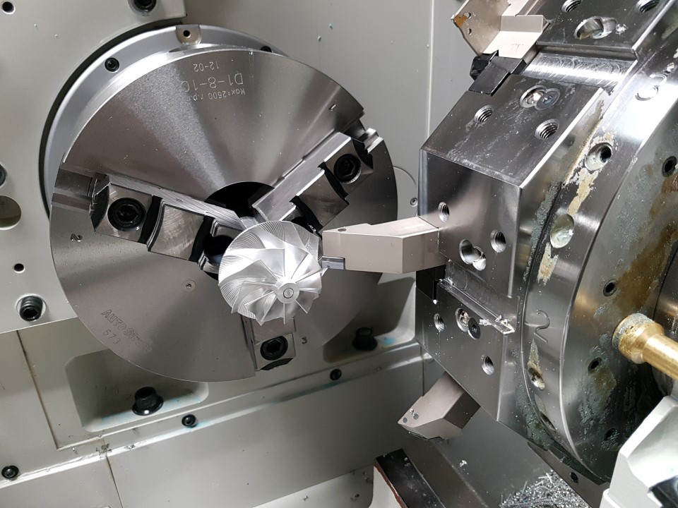
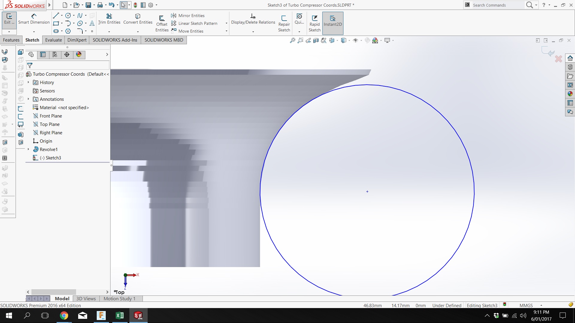
We've been using FeatureCam for CAM stuff at work, and its not to shabby, but I wanted to have a play with Fusion360. So far its far more intuitive, and there is a heap more support for it out there available on the interwebs. I cammed up a toolpath, modified the post processor a little to work better with our lathe controller and spun up the measure profile into a test piece. Its not bang on perfect yet, but its most of the way there. A few more measurements and tweaks, and that'll be the compressor wheel geometry sorted :-).

-
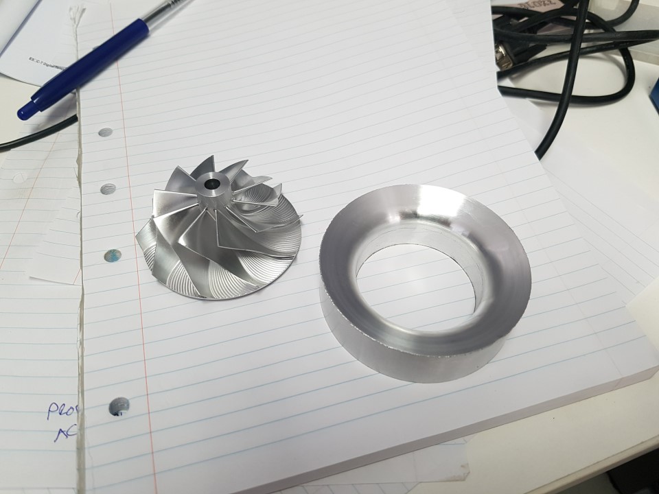
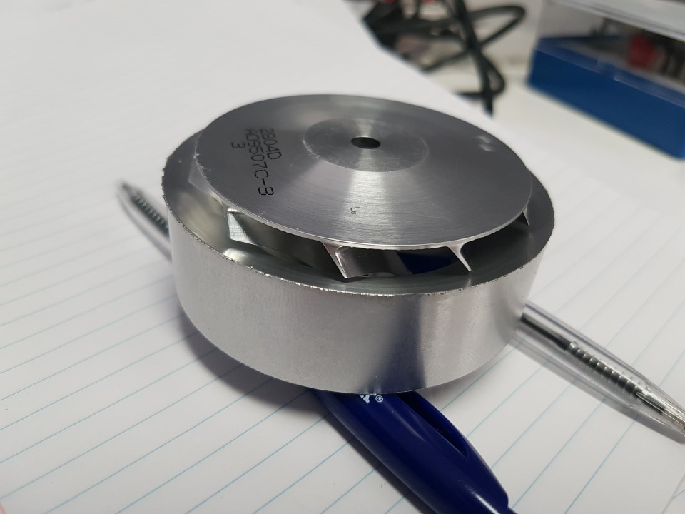
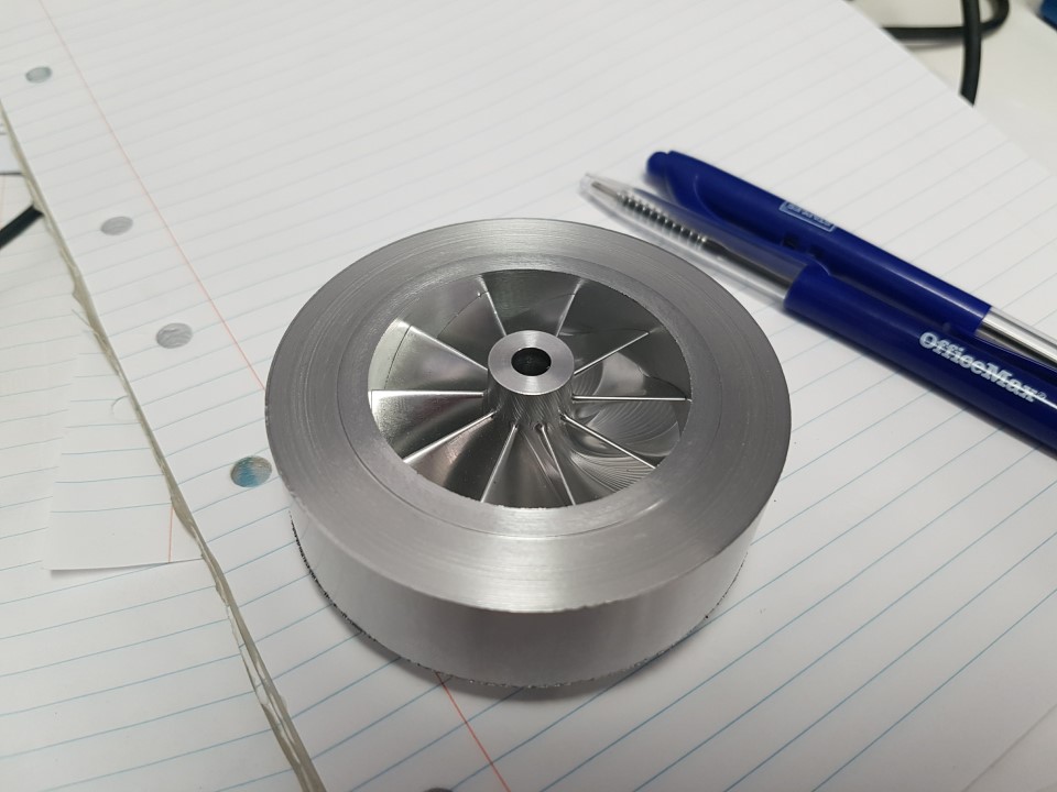
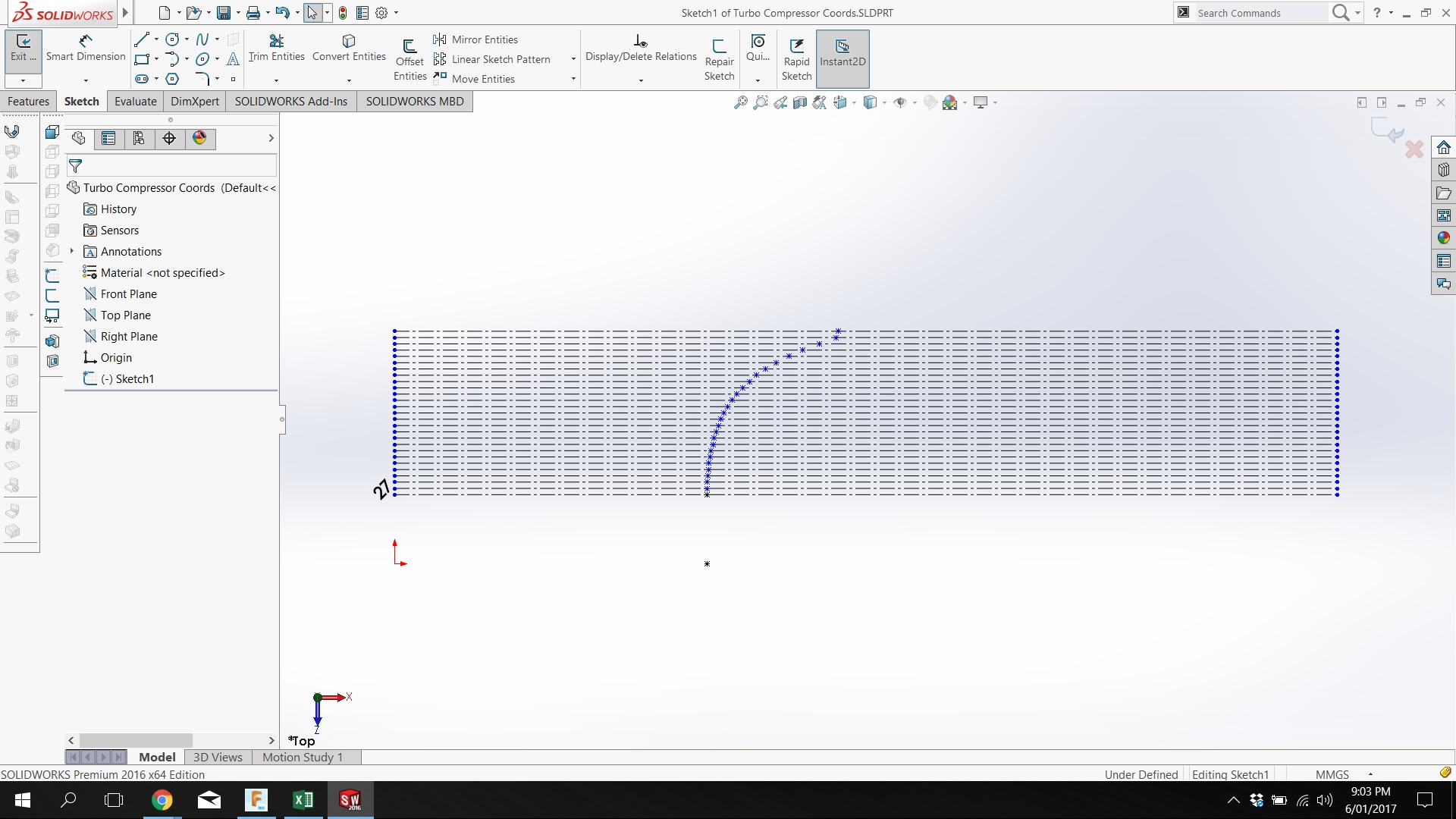
Next milestone I've decided to tackle is the measurement of the compressor and exhaust wheel geometry. I reckon this is probably the hardest part of the whole turbo endeavor as the data and machining has to be pretty damn close for the turbos to be efficient. I had a couple of ideas about this, but decided to start relatively simple and use the lathe. I spun up and arbor that the compressor wheel is a really good fit on, no wiggle, but it'll rotate freely. I started at the front edge, and moved the tool in till you could *just* feel the edge of it as you spun the compressor wheel by hand, and noted down this x-axis value. Moved back in the z-axis in 0.5mm increments, repeating the process till I got to the end of the blades. Not an ideal method by any stretch, but I got some data out of it to work with as a starting point. Popping the points into solidworks helped to visualize things, and got me here: I didnt expect this to be an ideal fit, as I hadent corrected my measured radius for the 0.4mm radius of the tool in the lathe, but as a starting point I rekon its a good one :-).
-
Chur buddy. One day I'd love to be that crazy math or science teacher at a secondary school ;-).
-
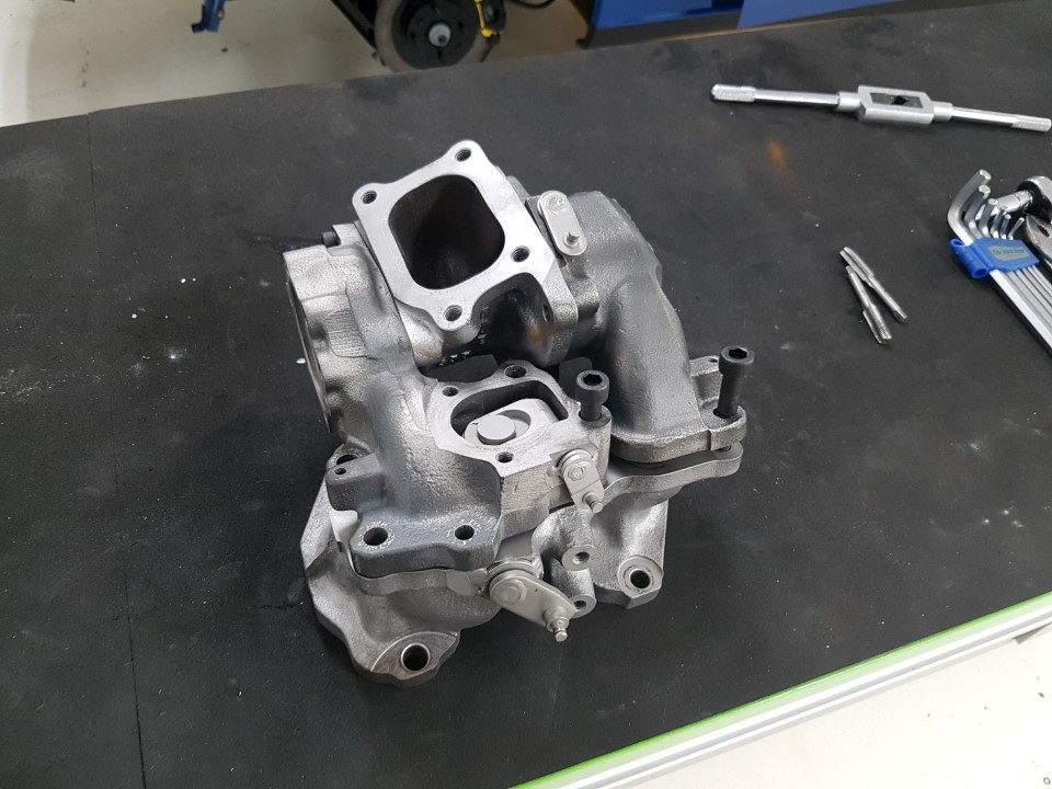
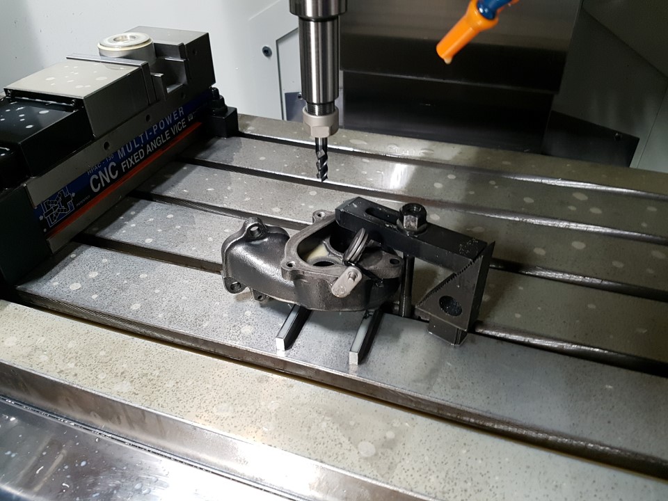
So part of the work I did while at work over the break was to clean up all the turbo housings, they all came up pretty nicely. The secondary turbine housings are well known for cracking really badly, but these replacement ones I've got are in really good nick, which is great That's the exhaust manifold, primary and secondary turbine housings, and the dump merge collector. It makes for a bloody chunky unit, and I'm sure contributes to a large amount of the heat issues under the bonnet of an FD. It heat soaks pretty quickly, and has such a migh mass it'll have heaps of heat to emit once the engine is off. Your engine bay stays warm for hours. With my plan to rebuild / upgrade the twin turbos I've got a few key milestones to hit: *) Increase size of factory wastegate port. Once you free up the exhaust a bit, its common to have boost control issues. A larger internal wastegate port should help with this. *) Measure and document geometry of replacement turbine and compressor wheels, so the factory Mazda turbine and compressor housings can be machined to match. *) Assemble garret T25 based CHRA's and have them balanced. *) Figure out what needs to be made / machined to fit the garret T25 CHRA's to the Mazda housings. The placement of the CHRA in relation to the housings will determine the location the measure geometry needs to be machined into, to make it all work. First to be knocked off was increasing the size of the wastegate port. I chose to do this on the mill as work, as its got a sweet probe that let me find the center of the existing port. Plus, it takes all the actual manual work out of it, because as well as being pretty simple, I'm also lazy. Yeah, I'm not a machinist, but this setup turned out to be rigid enough. I needed that much stickout on the endmill to clear the wastegate flapper. Took it out to 31mm. The flapper is 33.5mm, so leaves around 1.75mm of sealing surface each side. Not that these ever actually 'seal' per-say, but will still let it do its job. Was much easier than grinding them out by hand, which is how I've done it in the past.
-
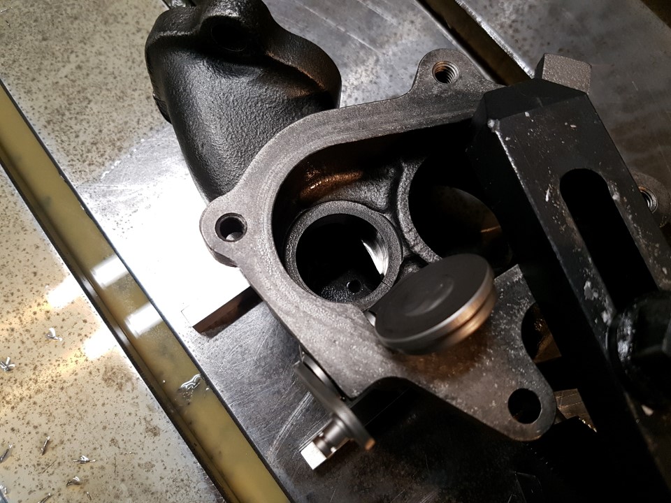
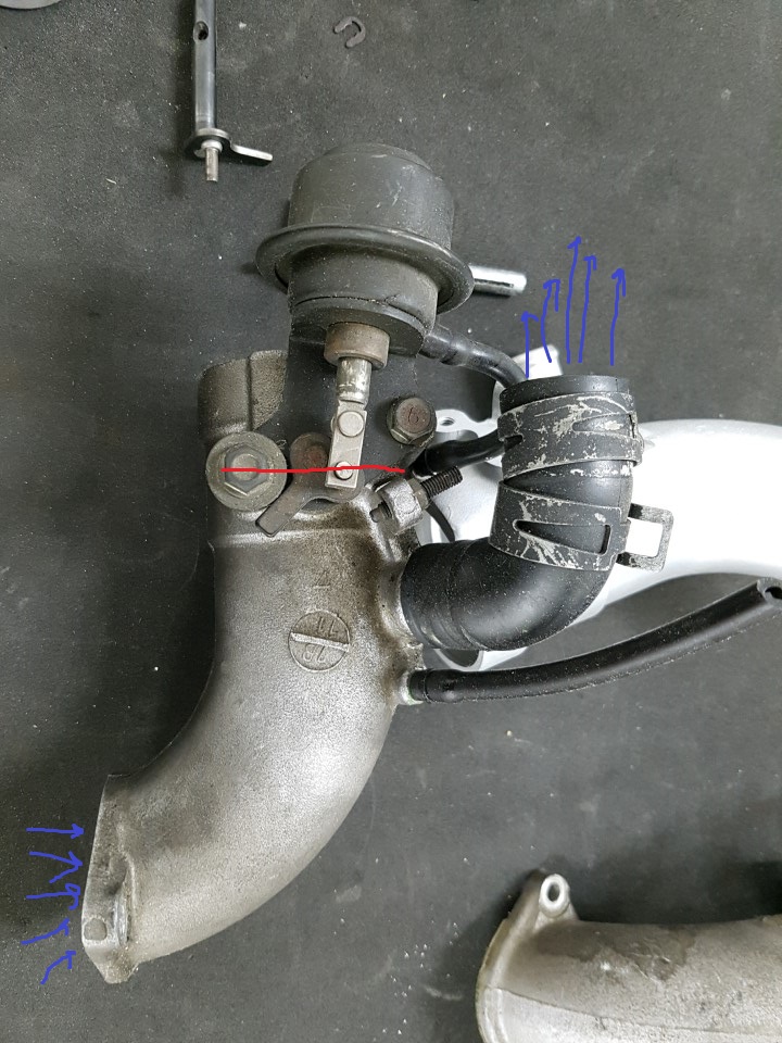
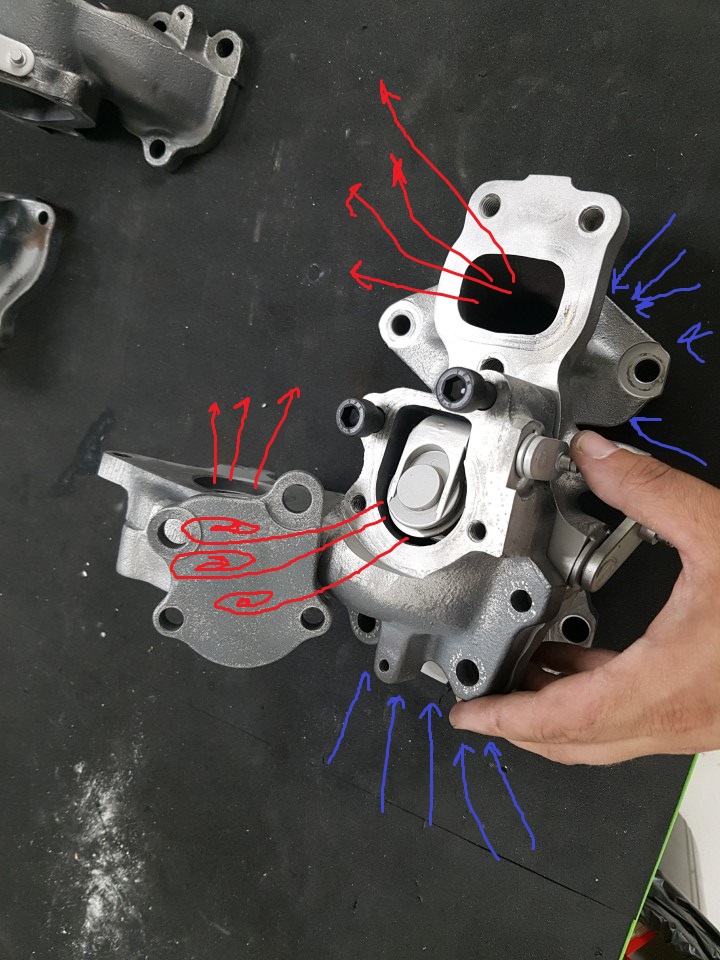
So what about boost control post switch-over, once both turbos are receiving a complete supply of exhaust gas and operating? Its a completely conventional internal wastegate system, with the wastegate flapper valve [FV3] located in the primary turbo housing. That's the primary turbine housing, showing inlet exhaust gas from the manifold, and where it can exit to the dump collector via either the turbine wheel, or [FV3]. Control of the boost both turbos create is achieved by just this single valve because at this point of operation, the exhaust manifold / primary turbine housing / secondary turbine housing system is one big open area essentially. Doesn't matter where in that area [FV3] is located, when it opens it'll bleed off exhaust manifold pressure, slowing down both turbos, therefore reducing output boost. There are bound to be a bunch of complicated airflow dynamics at play here also, but I choose to ignore those for simplicity, as I'm a simple kind of guy. Have you spotted the big missing link so far? To discuss that, we need to move to the compressor side of the turbos. The primary turbo has a completely conventional compressor side connection. The outlet of the compressor housing heads to the intercooler, and then to the throttlebody. Sweet, simple, my favorite. However, the secondary turbo needs some form of control on its output. If the secondary turbo compressor outlet was also directly connected to the intercooler, it is therefor also connected to the primary turbo compressor outlet. If the primary turbo is operating, and the secondary turbo isn't, the output boost from the primary will head back through the outlet of the secondary turbo, spinning it backwards and reversing the rotation of the earth. Now, as superman taught us, this is how you travel through time. I'm not a fan of being my own grandfather, so we need to avoid this at all costs. This is the pipe connected to the outlet of the secondary turbo compressor housing. Its in need of a clean up sorry, but I haven't gotten around to that yet. Its got another valve in it, which although you cant see, you can see the linkage and actuator. The valve looks EXACTLY like a throttle valve. There is yet another valve in this system which is missing from this picture alas. Its connected to the open end of the rubber pipe, and its a plastic valve that looks EXACTLY like a factory blow-off valve. So how to these work? Pre-switch over, the pipe is configured as above. As the primary turbo begins to build boost pressure, the throttlebody valve above is closed, preventing this pressure from entering the secondary turbo outlet and spinning it backwards, then being wasted back out to atmosphere. As [FV2] begins to open, bleeding off exhaust manifold pressure and begining to spool up the secondary turbo, the missing valve not pictured above (but connected to the open end of the rubber hose) is open, venting to the air box. This allows the secondary turbo to spool up, but without actually applying its output to the intake system. At switch-over point, the position of these valves is reversed. The secondary turbo is pre-spooled by the bled off pressure which is controlling the boost level currently, the throttlebody valve opens, connecting the output of the secondary turbo to the inlet system. The non-pictured plastic valve closes, preventing a massive intake system leak to atmosphere. Two turbo's, lots of exhaust flow, awesome! The pre-spooling of the secondary turbo is how Mazda manages to negate much of the 'Valley of Death' that sequential twin turbo Subarus suffer from. I've read some internet conjecture about the timing of the operation of these two valves. According to internet legend the non-pictured plastic valve closes before the throttlebody valve opens. This means the secondary turbo is spooling up, and its outlet air has nowhere to go. This causes it to surge, overspeed, and be spinning super fast in preparation for it being introduced to the intake system as the throttlebody valve is opened. Haven't read any literature from Mazda to that effect, but its a cool thought, and I read it on the internet, so its as good as being carved in stone I rekon. So yeah, sequential twin turbo system. Sick. Works bloody well when it works. There is of course the vacuum / boost / one way valve / accumulator / electrical system all laid on top of these mechanicals which has to be in perfect order for the system to function as intended... Sweet as!
-
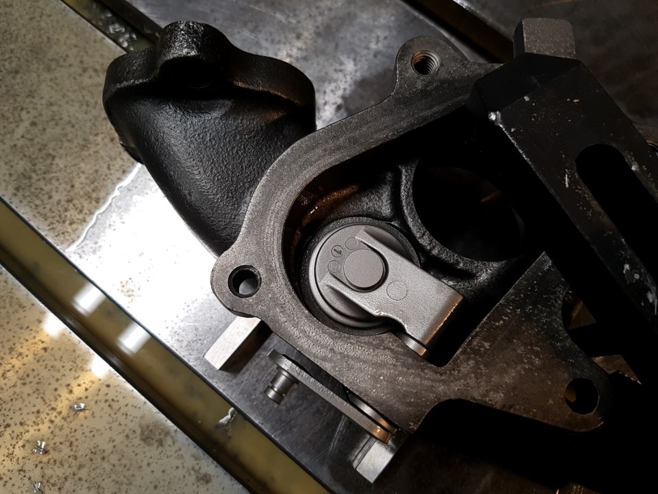
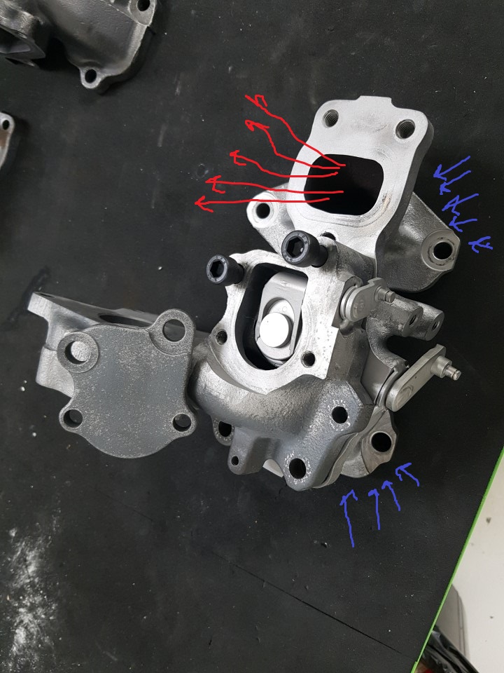
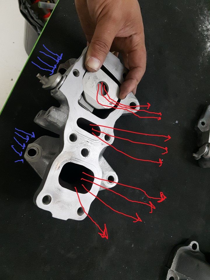
Which gets the system to this point. Everything is open, your turbos are both supplied with the rotary engines finest supply of exhaust gas. Max skiddage ensues till the redline, you're all happy. But what about controlling the boost level? Iiiiinteresting stuff there. The boost control system is split into a couple of phases, pre switch-over point, and post switch-over point. We'll start with the boost control before the switch over point. Mazda did something pretty clever here: That's the exhaust manifold with the secondary turbo turbine housing attached. I've removed the cast cover on the turbine housing to show another flapper valve, henceforth referred to as [FV2]. Pre switch-over, only the primary turbo is operation. We're about to have a surplus of exhaust gas in our manifold, which will push out primary turbo to extreme speeds and overboost our poor little motor. Best we relieve that eh? Currently the secondary turbo is sitting there idle, not receiving any exhaust gas. Late to the party it's probably having a cry and a quick masty. We need to get some exhaust gas to the secondary turbo ASAP! [FV2] and that middle outlet port on the exhaust manifold that I said to ignore earlier come into play here. The small passage feeds [FV2] which is now opened by (yet) another actuator. This has two effects, it relieves exhaust manifold pressure to control the overall boost level, and supplies the secondary turbo with a small amount of exhaust gas to begin spooling it up.
-
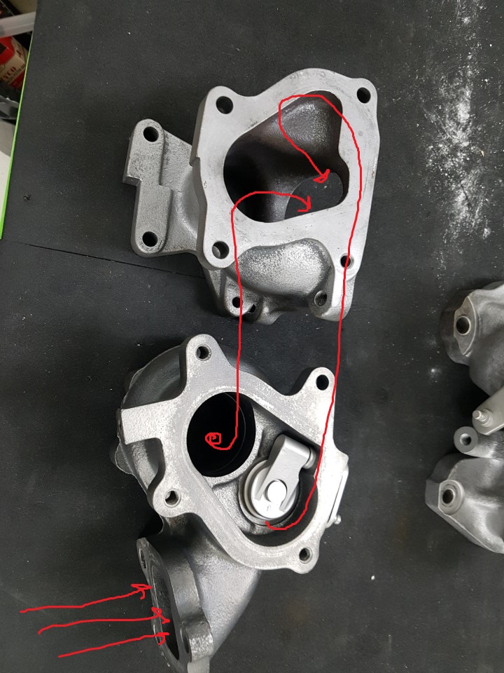
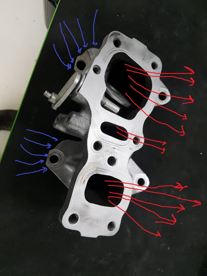
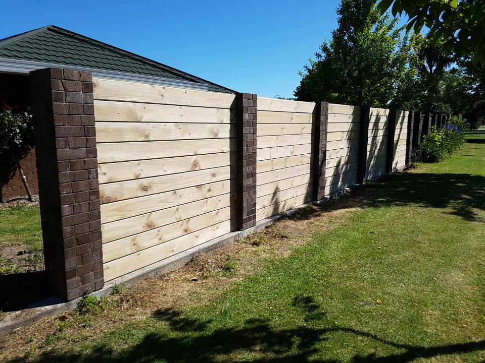
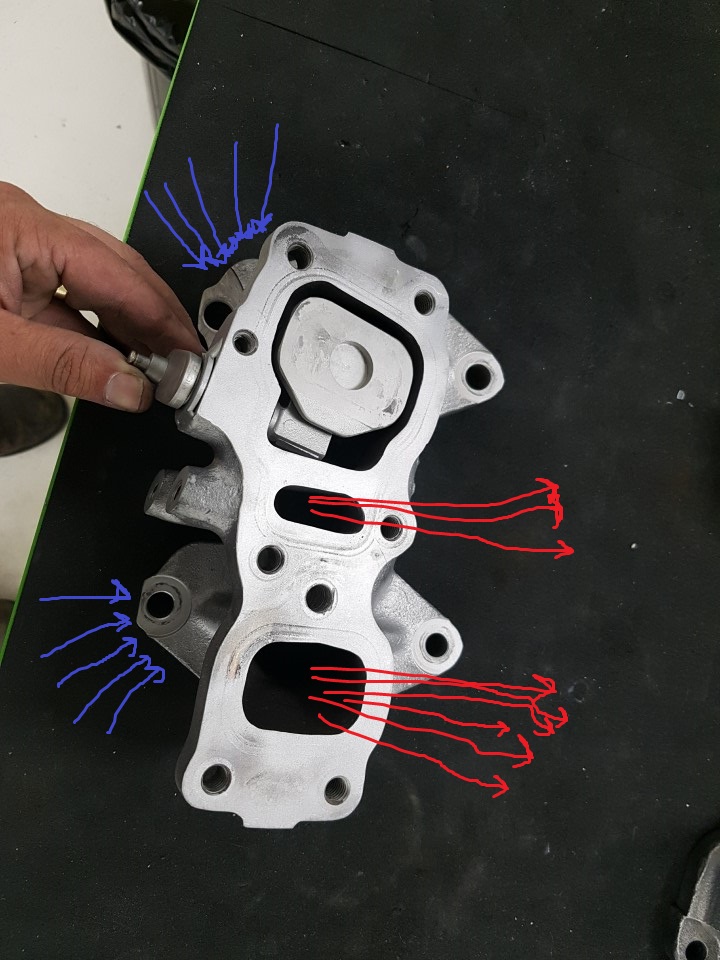
I've been doing some work on the 7 over the holidays. I had till the 8th off, so got a couple of days in at work before we went back to get some interesting jobs on this thing done. Not before i fulfilled a promise to wifey though, and got stage 1 (of about 10, eugh) of the front fence built: Brick columns are original (but were shorter), were shorter with brick panels in between. I cut apart the brick panels, cleaned off the bricks (the ones I didnt break, anyway...) and had the columns extended using these bricks to match the rest of the perimeter fence. New privacy / acoustic panels are 200x50 T&G retaining wall. Stout :-). We've had some really strong winds since, and nothing fell over, so I feel good about it ;-). But enough of home type stuff, more car type stuff. FD RX7's and their twin turbo systems.... For some reason I really like them. They're cool, weird, and kind of unreliable. I'm trying to cure as much of the unreliability issue on this car as I can, while giving it a little performance tickle up. First step was to actually understand how the system really works: As a quick run through of the operation, I'll look at the system as it would operate if you were cruising at around 1800rpm, and floored it, keeping it floored till red line in second gear. Remember, that's how you get sweet speeding tickets. Above is a picture of the stock exhaust manifold, with it's outlet ports that connect to the turbos facing up. The primary turbo bolts on the front (the bottom, in this picture) and the secondary turbo bolts on the rear (the top, in this picture). For the moment we'll ignore the little outlet port in the middle, and come back to its function a little later on. The passages inside the manifold are linked, so gas entering the rear manifold inlet port can exit the front outlet port, and vice versa. The manifold is a super nuggety piece of cast steel, with an interesting flapper valve, which we'll call [FV1] from here on out. Initially, at 1800rpm this flapper valve is as shown above, closed against the entry to the secondary turbo, preventing it from receiving any exhaust gas and operating. All the engine's exhaust gas is therefore exiting the front manifold outlet port, operating solely the the primary turbo. Sweeeeeet, fast boostage for max skids. As you can see, [FV1] is connected to an external linkage on the manifold, which is in-turn connected to a grunty double sided diaphragm actuator (not shown). When you hit around 3500rpm (not 100% on the exact figure, or if its solely RPM based) the system reaches the switch over point. At this time, the actuator connected to the external linkage is commanded to move... But the pressure in the exhaust manifold will be pushing against [FV1], keeping it closed. This is why [FV1] has a slightly odd construction, its a 2 stage unit. The first part of the actuator movement opens small orifice in the middle of the valve face, releasing enough pressure from the exhaust manifold to then allow the actuator to them open [FV1] the rest of the way...
-
I've read about people slotting the metal engine mounts 10mm in the engine side, and 10mm on the crossmember side to get the motors 20mm further forward so the CAS will clear the firewall. Probably a bit dodge though. With your engine being a turbo one from an RVR, does it have a CAS on the back of the head? I've also read about the turbo RVR engines moving the triggering gear to the front of the engine? It's all internet hearsay though, so take it with a grain of salt... If the CAS is your problem, there is a better way to fix it. With a bit of hunting, you should be able to source an intake cam gear and upper trigger sensor from a 2nd gen DSM Eclipse from the states. There is an aftermarket sensor solution that then puts the crank sensor a tthe front of the motor too, I cant remember the brand off the top of my head, but some googling and you'll find it. These bits then bolt to the front of your head / block and will allow you to do away with the CAS on the back of the head. The mounting bosse for the upper sensor will be there, but may or may not be drilled and tapped. If the gearbox you sourced is from a Sigma or similar, you'll strike issues with the shifter position, as its further rearward then the L200 boxes. The driveshaft output shaft outside diameter is also different (but I believe the internal spline is the same?). There is some info floating around from (I think) Trigger's ex lancer build thread about swapping the rear housing from the L200 gearbox to a sigma gearbox to get your shifter back in the right spot, and get the driveshaft sealing again. Isnt the internet fun? Giving you just enough un-reliable information to think something is a walk in the park.
-
I've only got the diff head, but a quick count shows 28 splines. Maybe the LSD nugget is swappable between the 8" and 9" models? Same number of bolts on the CW, will measure the hole spacing a little later on.
-
G'day guys. I promised I searched, but didn't find any really useful information. Anyone know the skinny on L200's and diffs? I've got an L200 LSD diff sitting infront of me, and wondering what model it would have come out of. It looks like all the pictures I can find of L200 diffs, but the crownwheel measures a good 225mm (9"). Its a 4.625 ratio, if that helps. Was purchased from trademe a couple of years ago as a 2nd gen L200 diff, but I have always been under the impression that 2nd gen L200's had 200mm (8") diffs in them. Muricans are always talking about swapping the 4.625 gears from dodge D50's (2nd gen L200's) into Starions, the majority of which over there have the 'big' diff, 200mm (8"). Because drag racing. Possibly this one is from a V6 4wd model or something? Weird. Kind of a bummer, as I wanted to fit the 3.54 cw and p from a US starion I have to it, and fit it to my 1st gen L200 for better open road revs. Anyone out there got an 8" L200 LSD diff they'd like to sell?
-
Cheers dude . Yes, go karts, quad bikes, all that fun stuff for sure .
-
Chur. Yeah, was good times. Hopefully it wont be too tricky to sell. It basically a completely stock, unusually tidy S7 Type RS. It'll have a couple of under the bonnet mods though, better intercooler, upgraded twin turbos, so should go a little better than stock, but still look really standard.
-
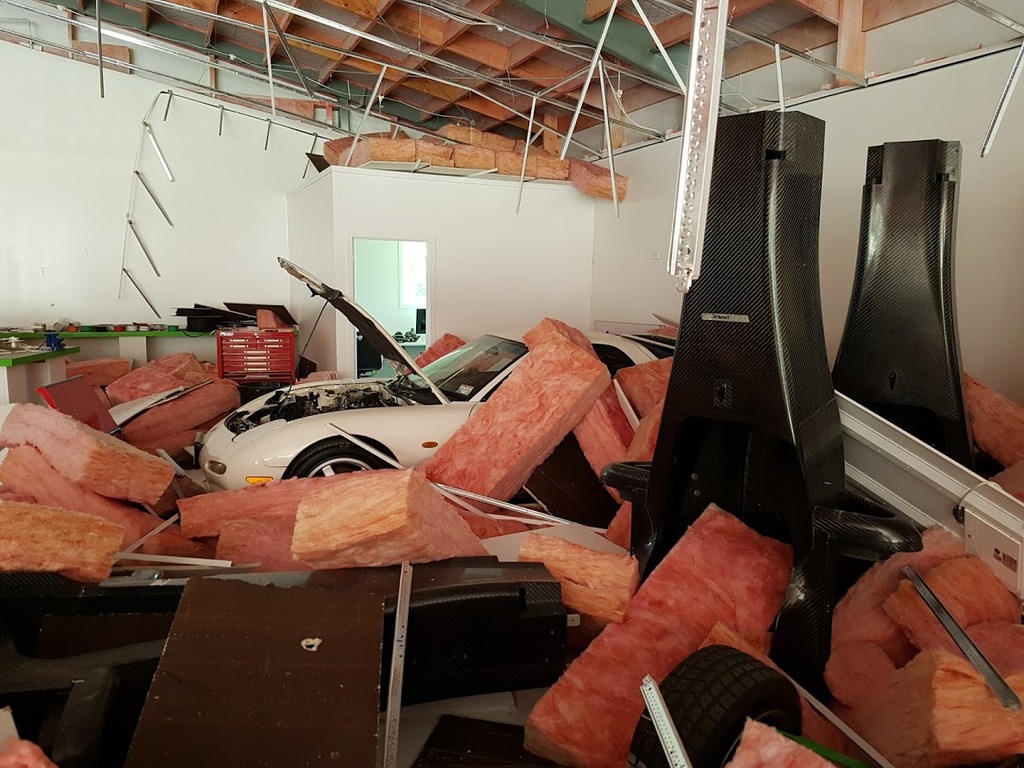
Yeah. Had it out at work to get some jobs on it done. We were only a few k's from the epicenter of the Waiau quake.
-
Well, that's not what you want. Lots of dings and scratches, but no real damage as far as I can tell. Punched the wall pretty hard, but hurt the wall and not the car. Luckily I updated the insurance on this thing just a couple of weeks prior to the EQ. Classic cover are purportedly really good, and their policy says the car is insured anywhere in NZ, so shouldn't be a problem to get it tidied up again. Then, I'm going to have to sell it. There is a mini-me on the way in a couple of months, so all the moneys is needed as we move down to one income for a while. Dang grown up issues!
-
Ted Huang's Starorion - 0R10N's 1988 Mitsuhishi Starion
ProZac replied to xsspeed's topic in Project Discussion
These could help. From an 86 starion electrical manual. 86 was a change over year for a bunch of electronics, but with yours not having climate control, should match up. -
In a completely non creepy way, I feel like you and I should be friends. . Super interested in what you're doing with the spark computer. I put some time into a crank / cam trigger setup for my Starion motor a while back, with the aim of having it all hidden behind the factory covers, and completely deleting the original distributor. Got as far as making the cam trigger setup, but needed some machinery I didn't have to get further. I should really pull it back out and continue with it.
-
Ted Huang's Starorion - 0R10N's 1988 Mitsuhishi Starion
ProZac replied to xsspeed's topic in Project Discussion
The lcd ones aren't a straight swap alas. Fuel sender and speedo sensor are different, plus a bunch of wiring changes, and the need for climate control hvac to make it all work factory like. The earlier LED part digital dashes are really laggy in the tacho department, you can rev the engine, the dash will begin to register it pretty much as the engine returns to idle. What you want is the analogue tacho from a gsr-v, they redline at 7' and go to 9 . At least being an 88 you'll have a vaguely useful volt gauge instead of a perpetually broken amp gauge. let me know if you have any issues with it, I've got a heap of parts still, and heaps of factory misty doc too. -
Ted Huang's Starorion - 0R10N's 1988 Mitsuhishi Starion
ProZac replied to xsspeed's topic in Project Discussion
Lovely purchase. I know you're all about the JDM, but the EX model Starion had some great features Atleast someone has already swapped the front bumper for a JDM one with the smaller license plate protrusion! Tasty car, love the widebody wheels on the narrowbody. I recently re-purchased my black car with the aim if turning it into a racecar for work. Should be fun to kick about in one again . -
Nah, I don't think so, there isn't anything super complicated or revolutionary on the cars. Most of the actuation systems (clutch, gearbox, etc) are from third party suppliers and pretty commonly used.
-
The cars are apparently really good, but no ones liked Lotus' marketing strategy. You had to buy the whole 'Exos Club' experience, involved a trainer, nutritionist, race series, etc... Plus you didn't get the car, Lotus prepared it and took it to the track for you. We'll offer support for them (both existing ones out in the world, and the ones we sell moving forward), but the owner actually get to keep the car they've bought and use it as they like.
-
Thus the reason for little work on the 7 in the last couple of months... The very last ever Lotus T125 ships to its new owner next week... Busy busy! Nothing outrageous on the motor front as far as work is concerned, power is much more efficient to just buy .
-
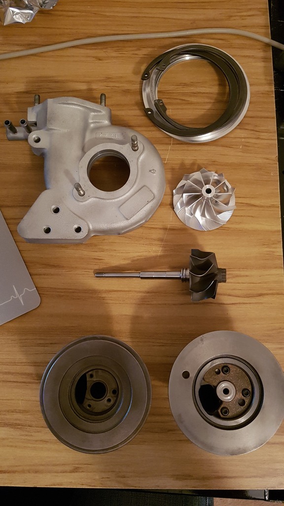
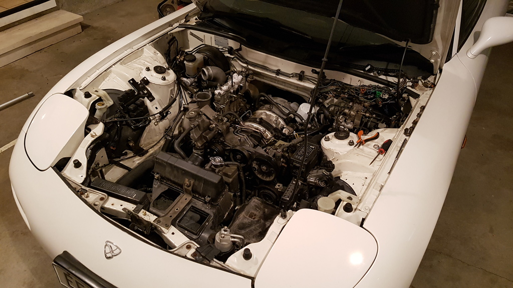
Hah, fat chance old man! Work got a little interesting in the last month... Bossman bought a Lotus T125 (google it, its cool). Actually, he didn't buy just one, he bought the complete defunct Lotus project, lock, stock and two huge fucking smoking barrels in the form of 40-foot containers, that then arrived, with said project contained within. Things at work are therefore a little busy, and haven't left me much time/motivation to tear further into the 7. We got one semi-complete rolling car, but it had no plumbing, or electrical system whatsoever... I run the Electron Management Department at work, so I've had to spend the last month trawling through Lotus documentation (which is SHOCKINGLY appalling / completely absent, by the way) figuring out their initial design intentions, which pieces of the puzzle we have, and getting the rest of the bits on the way... Then actually assembling the electrical system and building the wiring harness in a way that will keep the smoke on the inside. Massive challenge, massive fun, massive time-sink. I'm the fat one. But, in the evenings when I finally do get home, I wrote up a plan of the minimum I really need to do to get the car back and running it's finest: Rear suspension pillowballs. Re-seal the sump. Replace / rebuild the turbos. Replace all the injector seals. Replace the headunit with a factory cd-player from an NB MX5, for that factory clean look. Wire up the airbag on the NB MX5 Nardi wheel I've installed (again, for that factory look). Build a new wiring harness. I've started by removing the turbos. No real damage to them, just a bit of shaft play and obviously pretty leaky. If anyone ever asks you to come help them remove the turbos from their FD RX7, with the motor still in the car, you go tell them to fuck themselves, right in the ear. What a cunt of a job. Additionally, even more annoying, as I'll pull the motor to re-seal the sump anyway, so the struggling was completely moot. Pricing up rebuild kits for the Hitachi HT12 turbos on the FD was a little frustrating, as the RX7 versions of these turbos don't use a dynamic piston ring seal on the compressor side, they use a friction carbon seal. Makes bits harder to find, and ass-puckeringly expensive. I'm going to try something cheaper (and cooler) first. A buddy had a stuffed pair of R32 GTR T28 turbos kicking about that had both spat their ceramic turbine wheels. I pulled them apart, and there isn't really much else wrong with them, so I have a plan to rebuild the cores with some new bits, and try to cludge them into the factory RX7 exhaust and compressor housings. I ali-expressed some rebuild kits, replacement steel turbine wheels and some fancy billet compressor wheels. I did a lot of boring staring the compressor and turbine wheel maps, figuring out that, yeah, all the sizings should be in the ballpark for some increased efficiency at slightly higher than stock boost levels. We've got a CNC lathe at work which I've been getting rather intimate with... It uses a pretty orphan controller (Anilam), which I've gotten to know pretty well, as I had to write the post-processor our CAM software then uses to output G-Code which will make things not crash into one another. It's all working pretty sweetly now, and was a great learning experience. I'll use that to both measure the profiles of the curves of the compressor and turbine wheels, then machine the housings to match. Simple in theory, but as I'm quickly learning, fixturing this shit so its actually possible to machine is a real ball-ache. Also, we don't have a 4-jaw, so I'm not 100% on how I'm going to get everything completely concentric, but some custom fixturing devices will be made and I'll see how far I can get. Replacement GT28 wheels(Compressor 49.70 / 67.40mm, Turbine 46.95 / 53mm), Hitachi CHRA bottom right, Garrett T28 CHRA bottom left. Then I did some more googling and it turns out a place already does almost exactly this modification and calls them the BNR Stage 3's. Damn, I thought I was being cool and original. Still I'm only into the modification for around $180, so if I can make it work it'll be pretty sweet .
-
Deja Vu! After many, many k's (around 20,000 of them) of trouble free motoring... The seven developed some.... Problems. Nothing too serious though. Turbos are very very leaky, causing lots of smoke, and a 1/2" puddle of oil in the bottom of my intercooler (no exaggeration). The sump leaks from the interface to the block, very common issue, and the rear suspension pillowballs are a bit clunky. I've settled into my new job pretty well now, and have a good routine going, so I can squeeze out a little time to get this thing sorted and running its best again. I had been commuting to work in it (around 1250k's a week) and it was surprising frugal! That is a complete lie. It was costing $300 a week in fuel... Not really a long term dooable thing. I got all boring and went and bought a B7 Audi A4 TDI sedan. Its got leather, good stereo, and cruise control, oh and does 1200k's to a tank easy on the open road, so I only have to fill it once a week. So with something reliable to daily (reliable-ish anyway, there is a story there, but is a good argument for purchasing from a dealer sometimes), I've put this in the garage, given it the clean of its lifetime (best to work on a clean car ) and torn into it. There will also be some light modification this time, so really get the best out of this car. I miss driving it already, so hopefully I can knock this out within a somewhat reasonable timeframe. Work Ahoy!