zep
-
Posts
4664 -
Joined
-
Last visited
Everything posted by zep
-
When I first got started with this, I measured how low the mount would need to be from the axle centre to make parallel lower arms that bolt directly into the stock chassis trailing arm mount - answer: it was MUCH lower than the 2.5" drop suggested in the Escort manual. More like 3.5-4" from the axle centre. I guess what I'm trying to say, is that I have plenty of room to slope down towards the diff if I'm remaking the mounts at both ends. I will also be developing this with the car in it's already lowered state, so it should stay pretty much where it is. Although I'm not sure why it's harder to run the lower bars up to the chassis, rather than parallel. Surely going up is better for clearance (assuming you making all the mounts in the locations you want). I need to do some more reading up about roll steer, etc. This setup will have a panhard rod. In the end, this is a street car and I'm more interested in putting down power out of corners on the back roads than doing a 10.
-
It's just an excel one that I found somewhere. Yeah, it seems like half the internet is saying, just put something together, it'll most probably work VS 1mm difference and there will be DRASTIC changes to the handling.
-
Thanks Tom. The 4 link was always something that I wanted to do. The ladder bar was just the easiest and most cost effective method to get the diff in at the time. Also, Clint came by for a chat about a few other cert things and mentioned that my current setup would not be certifiable these days. It's to do with all the forces trying to pull and push the single joint at the chassis up and down. I've read that the best thing to do is to try get the IC to lie on the anti squat line. Unfortunately, getting an accurate line is difficult as measuring the CG height is not easy without a good industrial scale. If I angle the top bar down, it's there an optimal height or should mount above the lower bar at the chassis end? Because the car is relatively short wheelbase, getting the IC inside the wheelbase would mean quite a steep downward angle. If the upper bar is left longer it would end up very close to the lower mounting point, bringing the movement closer back to a ladder bar, wouldn't it? I'll have another play around with my 4 link calculator. Haven't managed to find a metric one yet though!
-
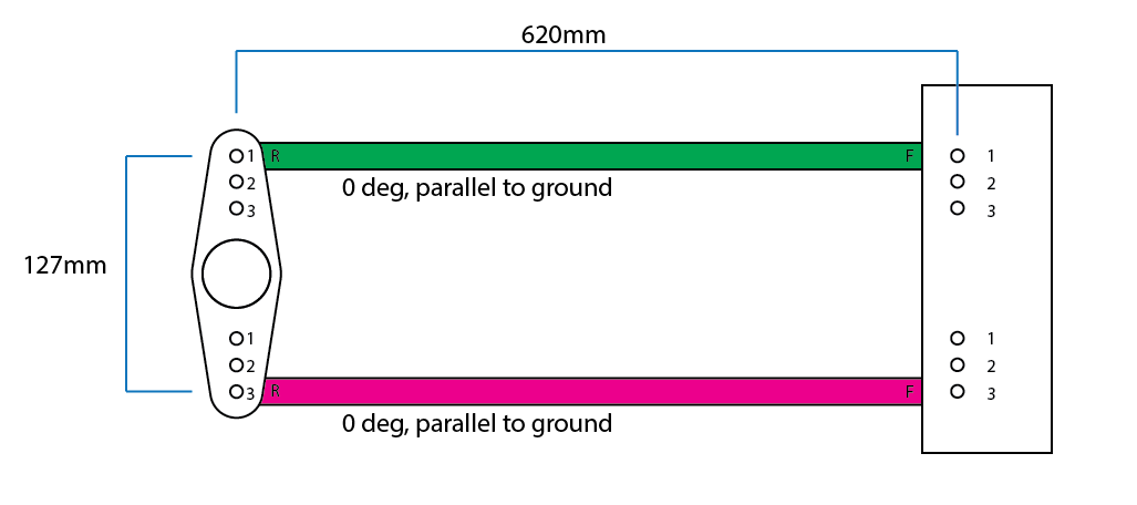
I am working on figuring out how to 4-link my Gemini and I need some guidance around arm lengths and angles. I'm basing it off the Escort Rally prep manual as the Gemini and Mk2 Escort share the same wheelbase. In this, they run 23" arms, mounted 2.5" from the axle centre, both parallel with the ground. I am aware that the length and angles of the arms can have significant affect on anti-squat and roll steer. At the moment, I've designed it as seen below: 620mm is the stock length of the Gemini lower trailing arm mounting point to the axle centre, 127mm is the same as the Escort setup. However, I have read varying warnings about running the bar angles every which way. Both parallel; lower parallel, top angled down; bottom angled up, top angled down; etc. And then some people run different length bars, or the bars mounted forward or rearward of the axle centre. There is a lot to think about. I've worked out that if I run the lower parallel and the top angled down 25mm at the front or 2.346°, I'll get a figure of 30% anti-squat and the IC will be about 500mm in front of the front wheel. I don't know exactly where the centre of gravity line runs in the car, but after playing around with a 4-link calculator I'm struggling to get the IC inside the car without some quite funky arm angles. Bear in mind, this is not a drag car looking for that 1/10th of a second grip off the line, so I'm not overly concerned with some squat to get grip. I guess what I'm asking is - and I know every car is different - what would you do? The Escort seems to be pretty well proven, although it is a rally car. Just allow my self enough adjustability to make any changes I might need to?

-
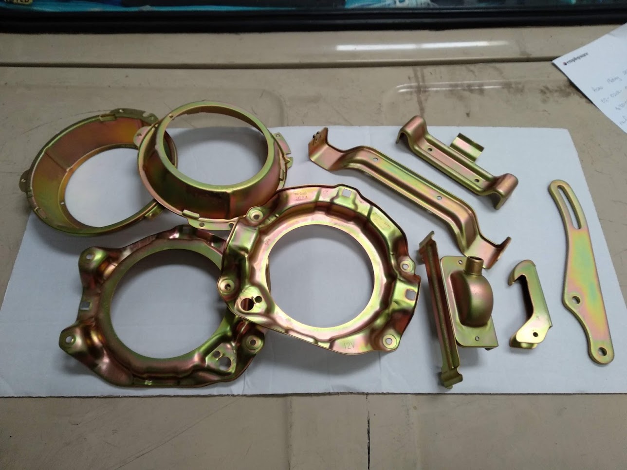
Got some bits back from the platers. Thanks to Brett for vapour blasting them first!
- 73 replies
-
- 15
-

-
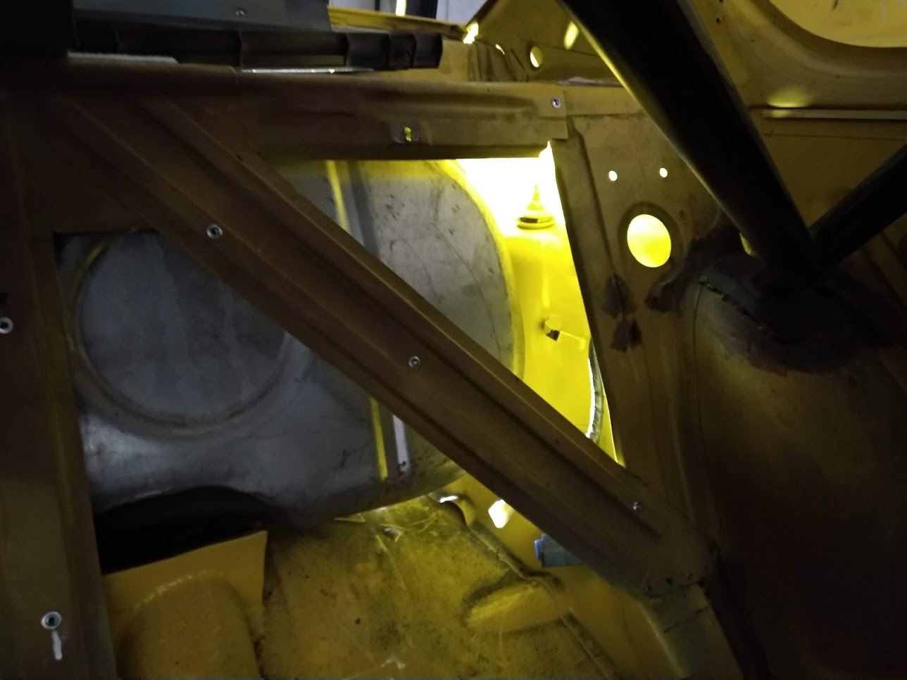
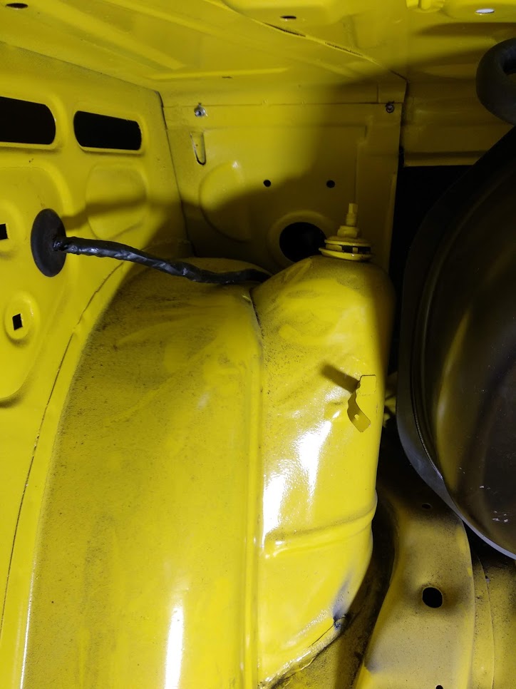
I'm really spamming this thread these days. I'm interested in converting my spring and shock rear to coilover. What needs to be done in terms of strengthening the turret and the mount on the diff. Here's how the shocks mount to the diff normally: Here's the turret: And I also have the cage in the rear that I could potentially tie it in to (sorry for this shocking photo, I hope you get the idea): Cheers boys.
-
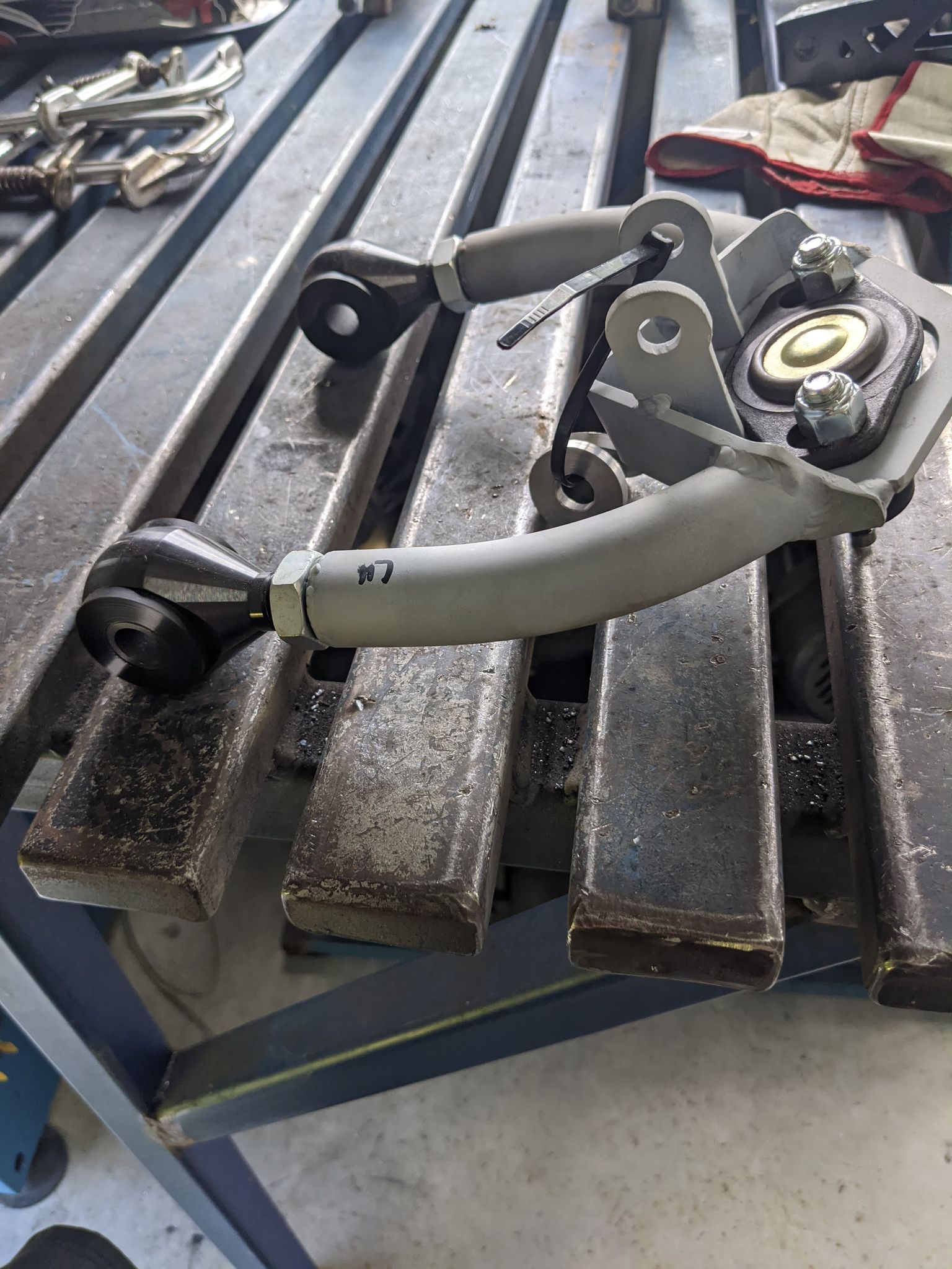
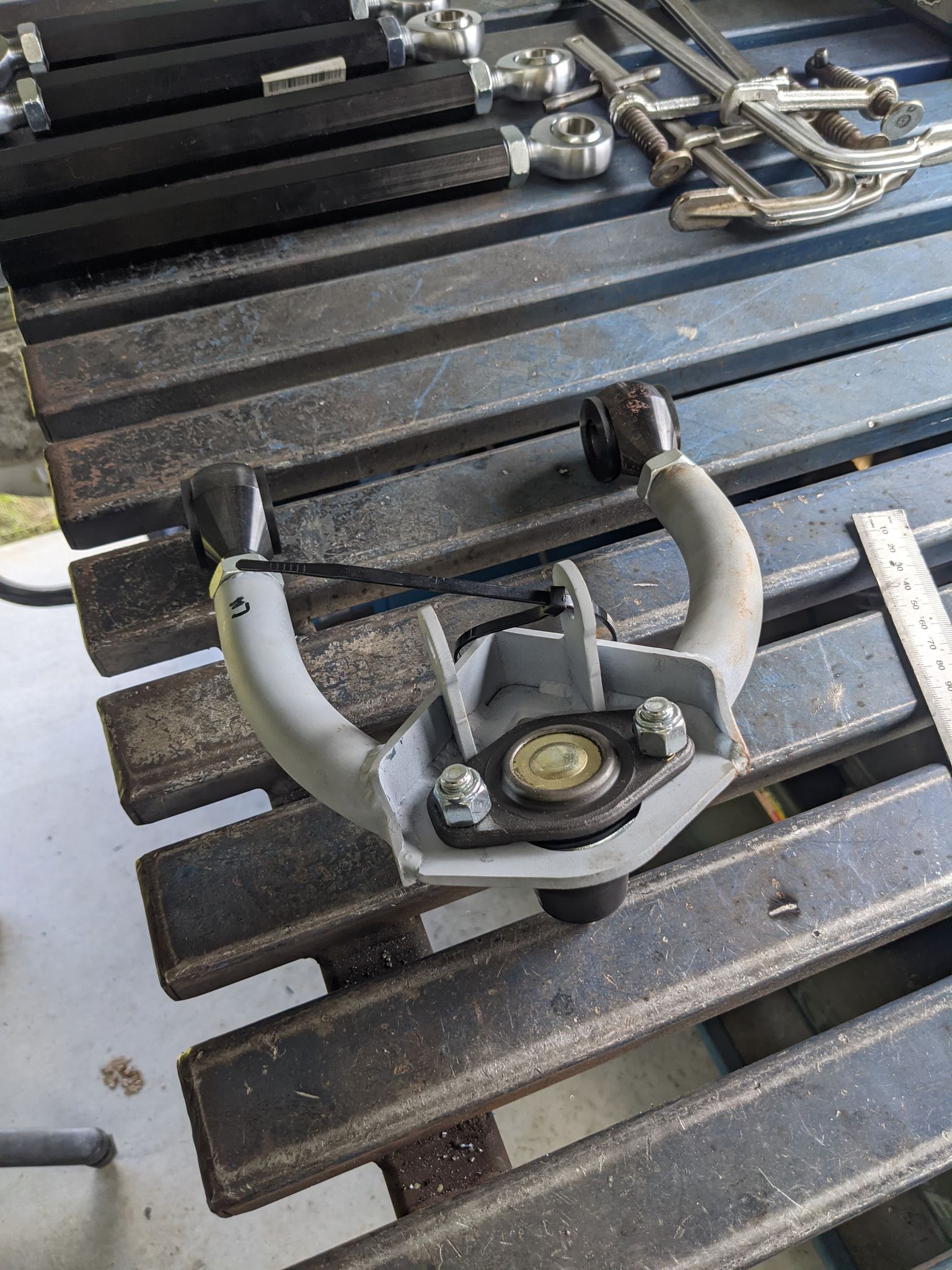
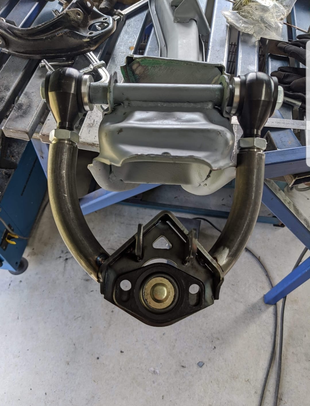
Hey @cletus The place that makes them is called FabHouse: https://www.facebook.com/FabHouse05 Here are a few more pics and some info the owner gave me: "They are made from 3mm CDs tube all tig welded uppers are factory length with adjustment rubber bushes heims joints and fit the slotted ball joints for extra adjustment"
-
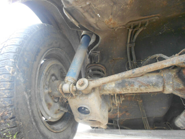
Hey @cletus, these upper A arms are being made in Aussie and will be "engineerable in QLD". Assuming the welding and clearance are good, do they look certable in NZ? They are bolt in and give more caster and camber adjustment than the stock arms. Stock arm for reference:
-
Sweet. I need to double check that 10mm wont mean the bolts interfere with the hub, but it should be okay. I am still in the planning stage of working out the shape, but yes, they will dogleg back like the stock ones, maybe 10mm further back. I may be able to have a mate CAD them up and CNC cut them so they are one piece with no welding needed.
-
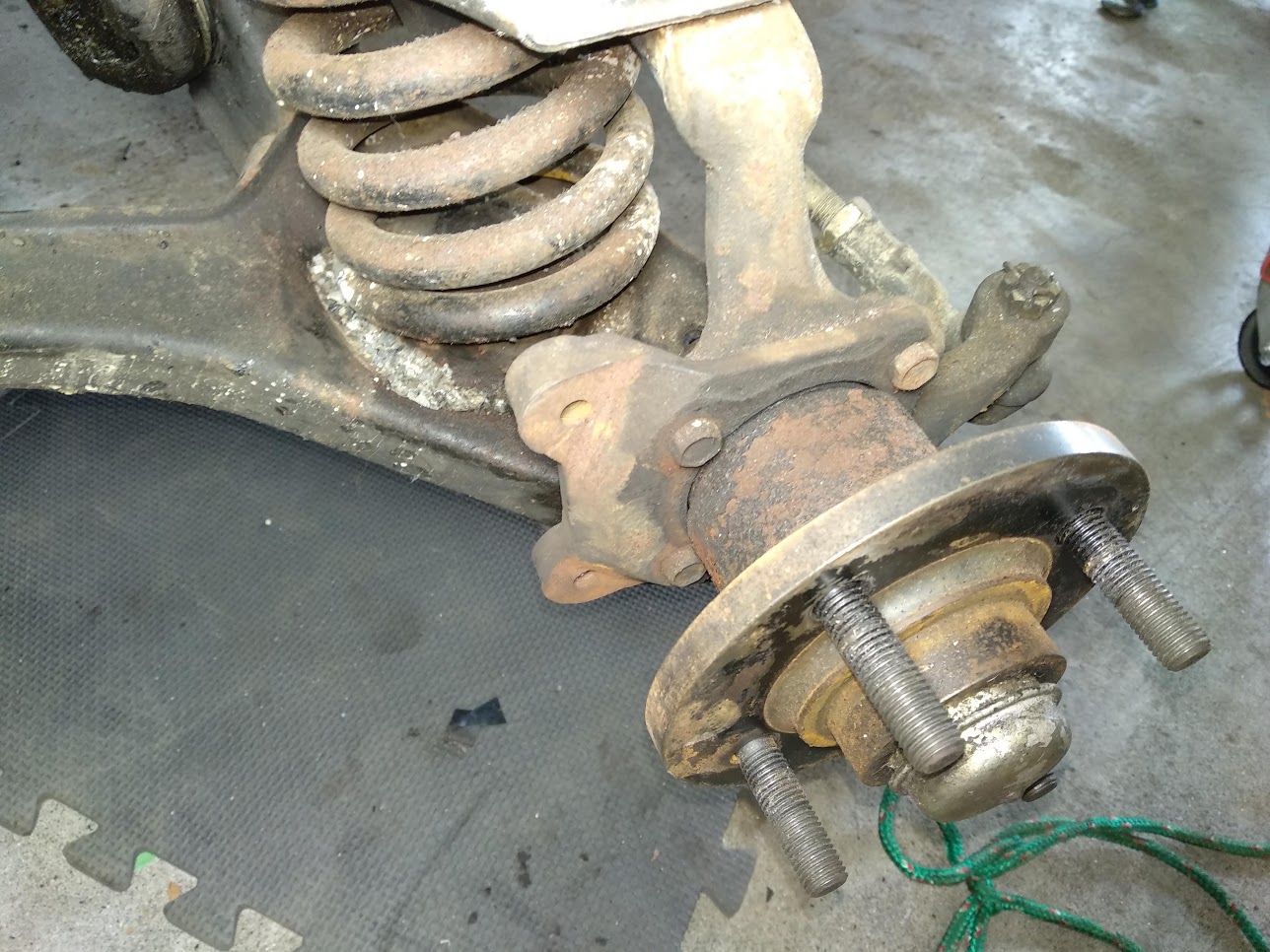
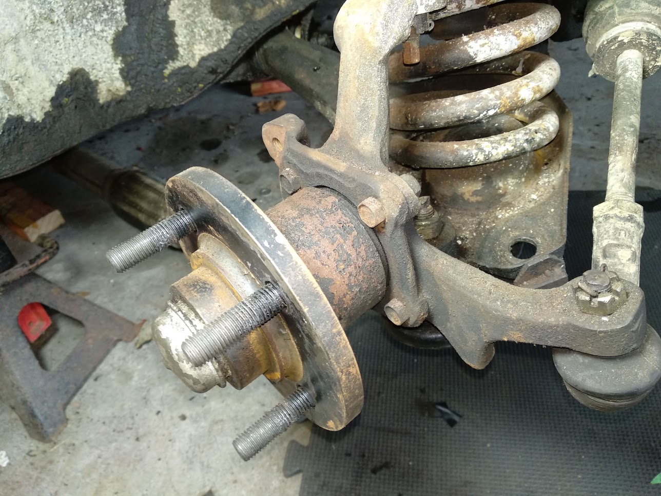
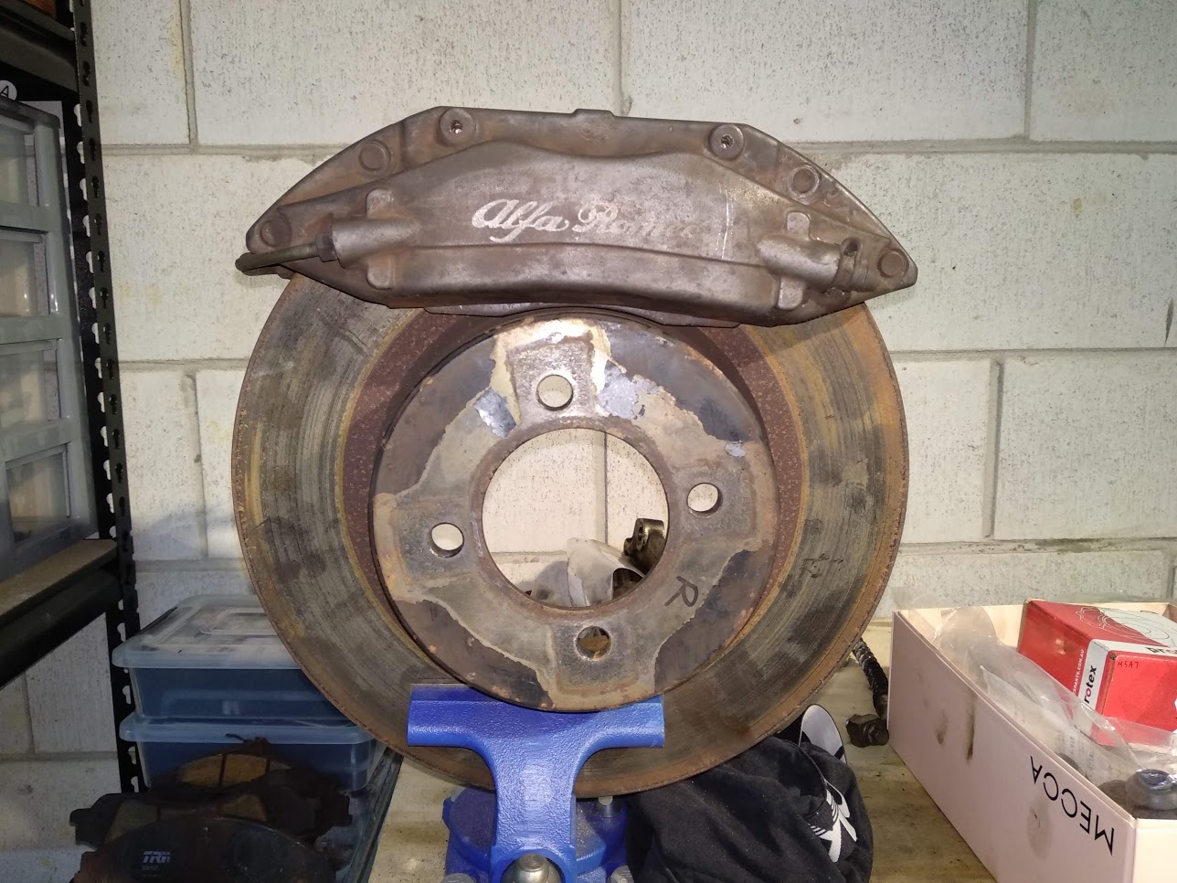
Hey @cletus - I'm looking to fabricate new caliper mounts for some Brembos I've got my hands on. Essentially, they will be similar to those in the pics below, but the bolt holes will be spaced wider apart and will sit back towards the car about 10mm more than current. Is there anything I need to be aware of in terms of metal types, strength, thickness etc?
-
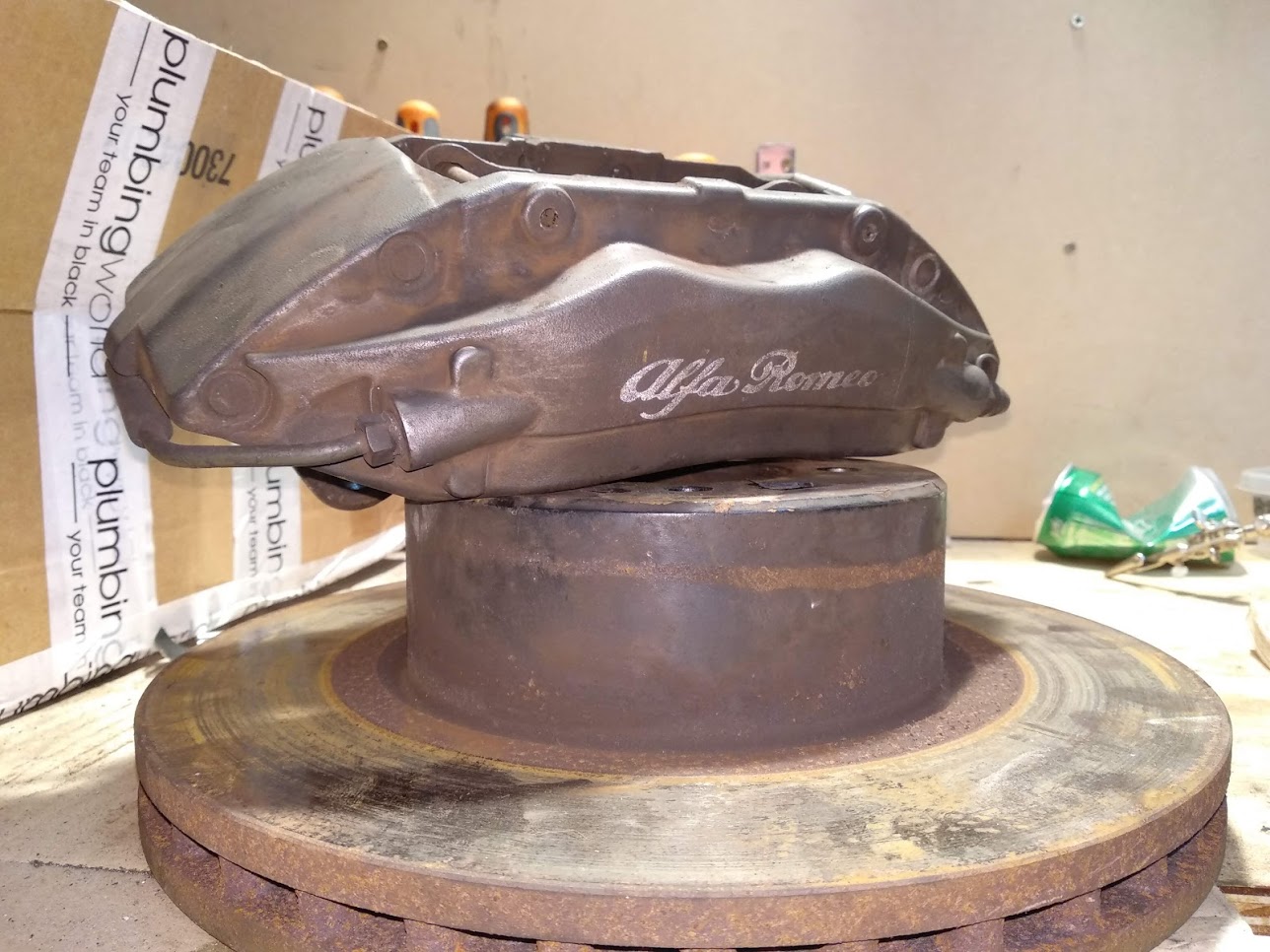
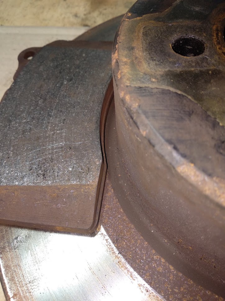
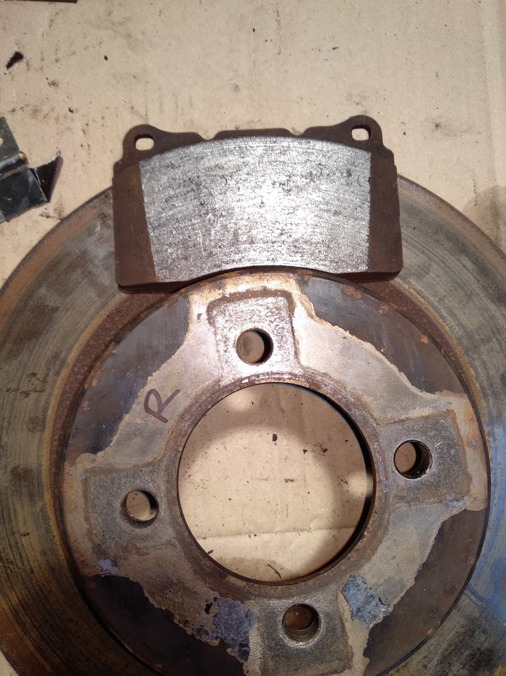
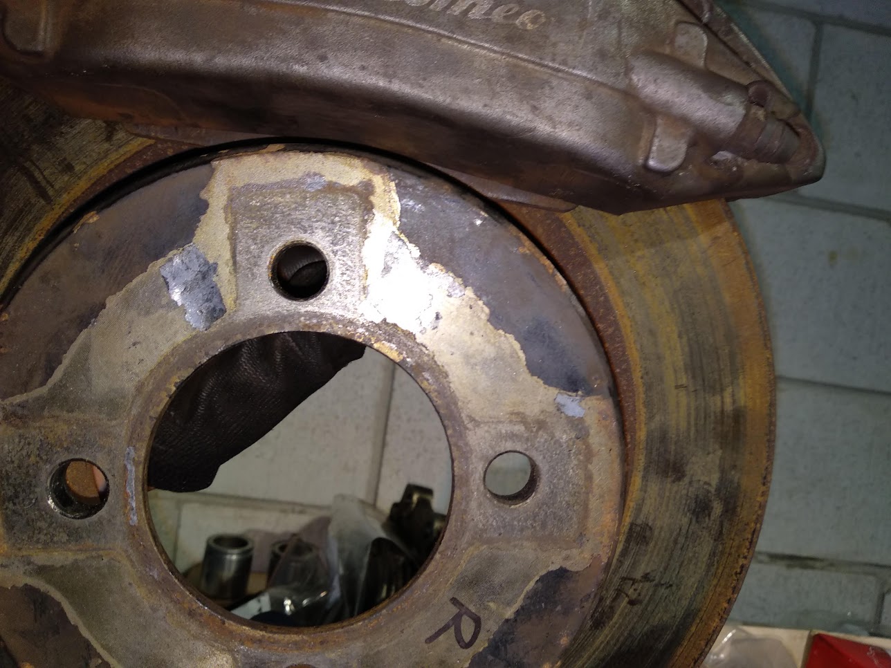
So @Abarthand I were out at Pick A Part last weekend failing to remove a Fiat crank when we stumbled across an Alfa Romeo 159 3.2 V6. Some guy on my street has two 156 GTAs and I have been eyeing up the brakes. Fortunately, the 159's brakes were still there, and yep they are 4-pot Brembos. For $49 a caliper I figured I'd see if I could make them fit on my current setup some how. Obviously some machining/engineering is necessary but it looks like they *just* might! It is super close though. The pad material uses 100% of the braking surface on the rotor. The total pad hangs over by like 1mm. Bear in mind the 159s have 330mm rotors and mine are 296mm. Here the pad is lined up with the outside of the rotor. It's hard to see but it is literally perfect. You can see how much larger they are than the VT Commodore pads. Here's the bottom of the pad: Is this acceptable? Will I run into any issues? Pretty hard to take a picture on my own holding up the caliper, but you can kinda see the clearance here. And here's what they look like on the rotor. They are not in the right position though, would move up a few mm. I measured about 8mm between the inside of the rotor and the pad.
- 73 replies
-
- 16
-
-
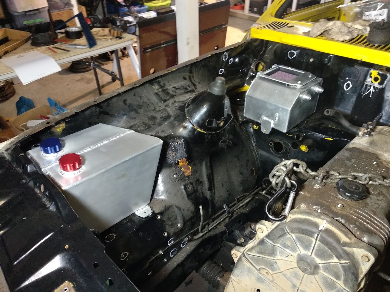
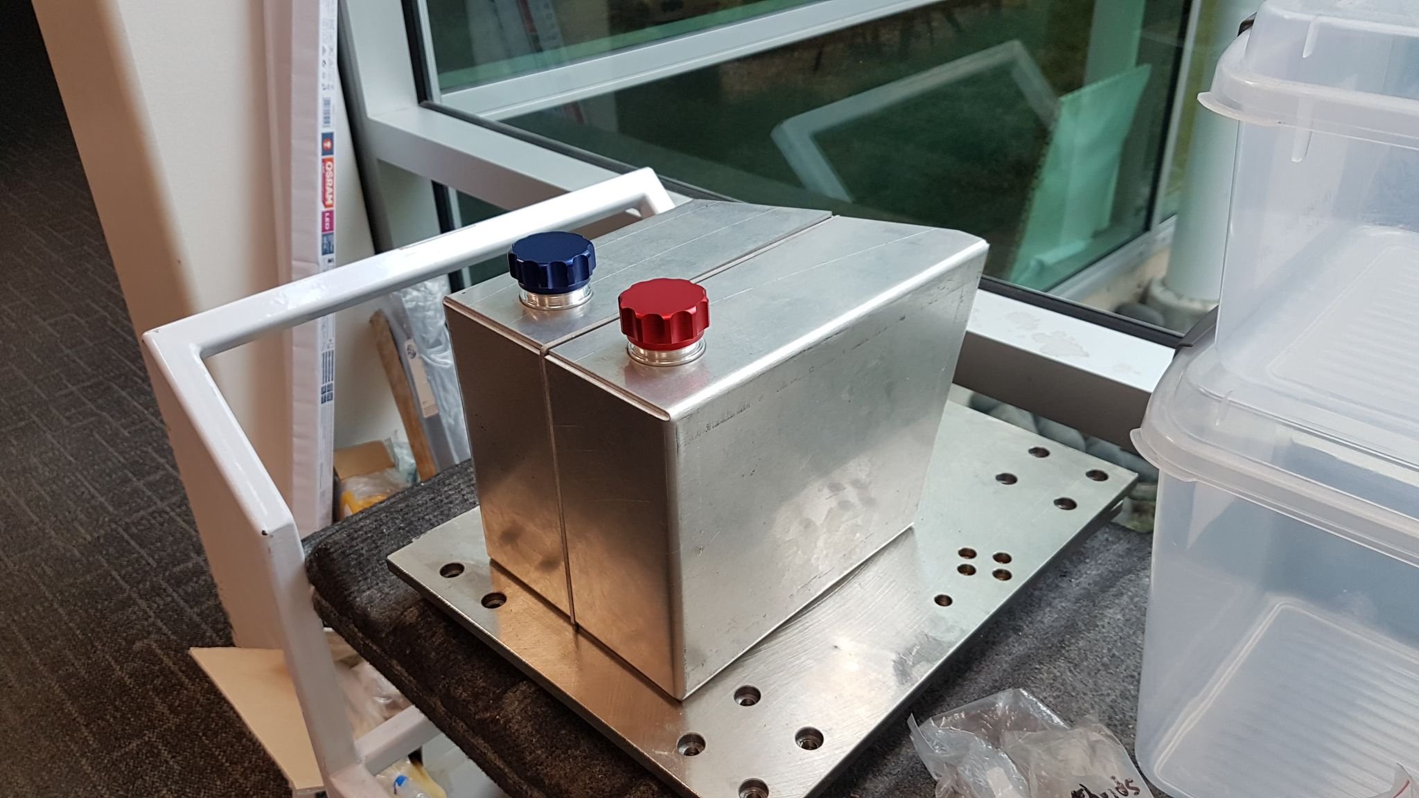
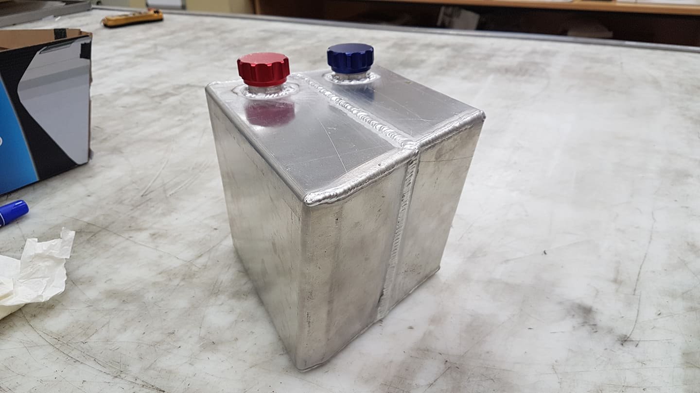
Both the catch can and the dual reservoirs have finally been completed! I just need to get them mounted in their spots and I'm pretty much ready to start on panel and paint. I've found an old boy who's keen to do so am pretty happy!
- 73 replies
-
- 16
-
-
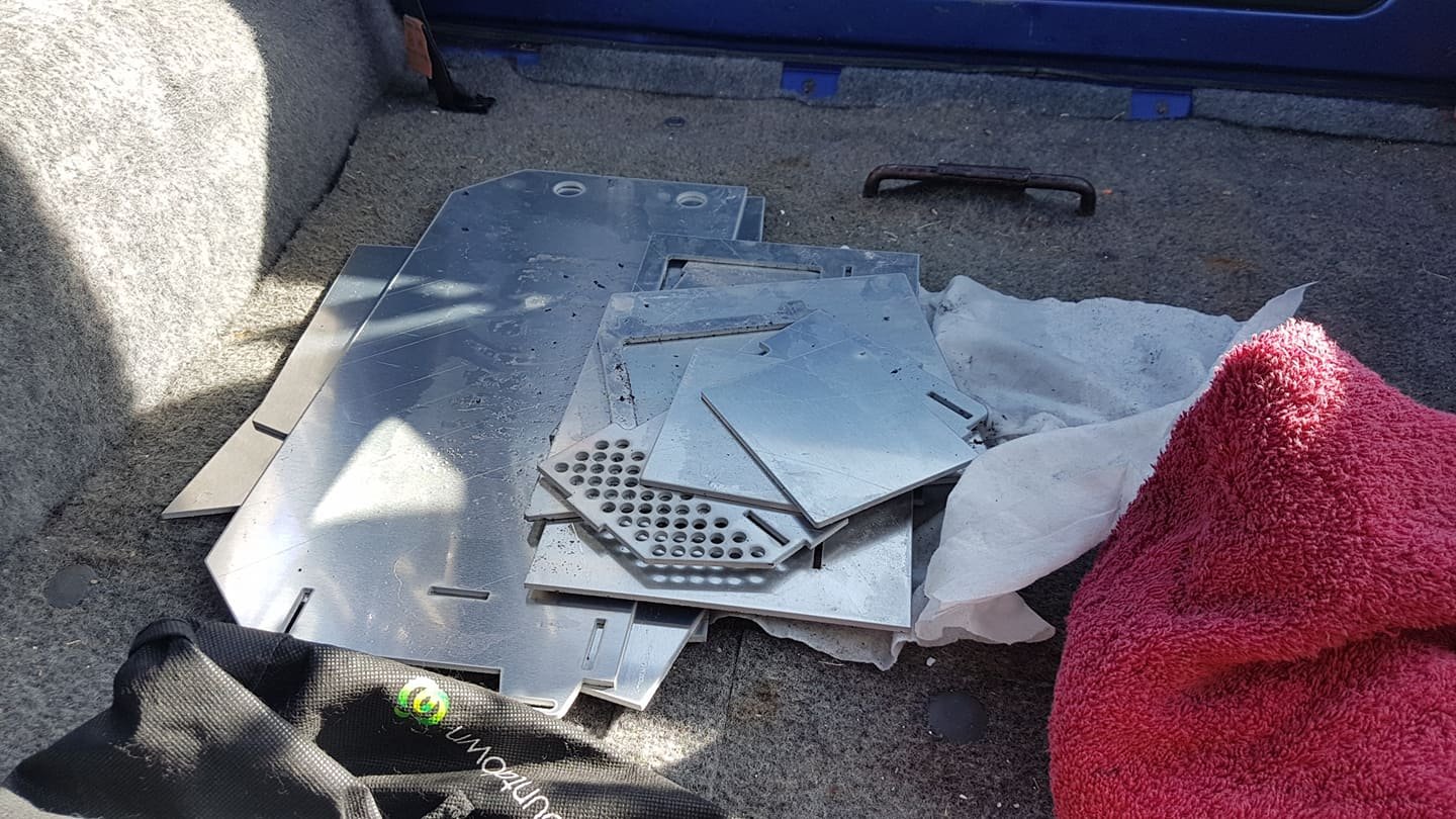
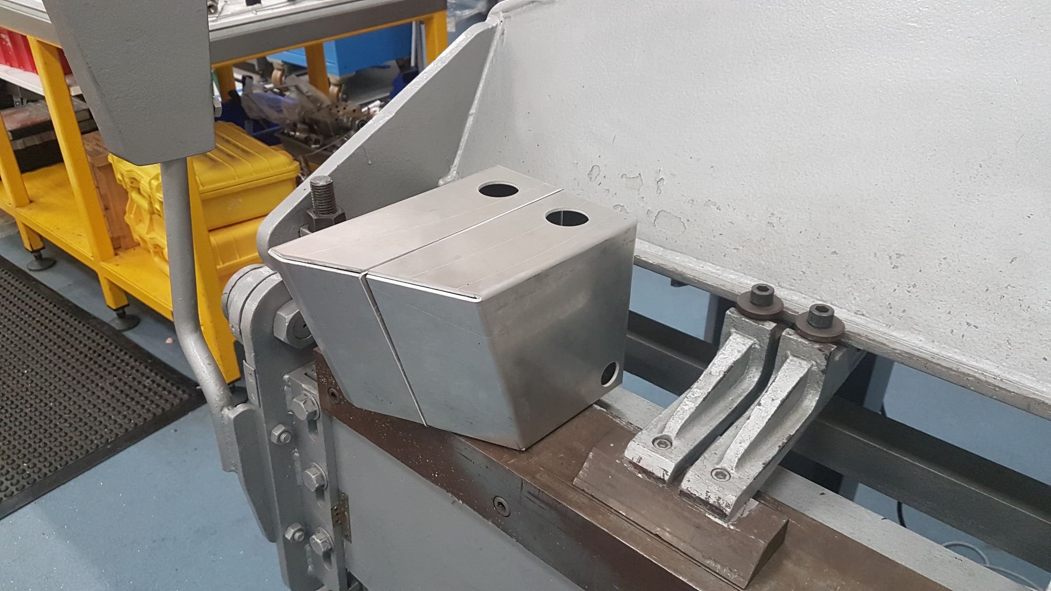
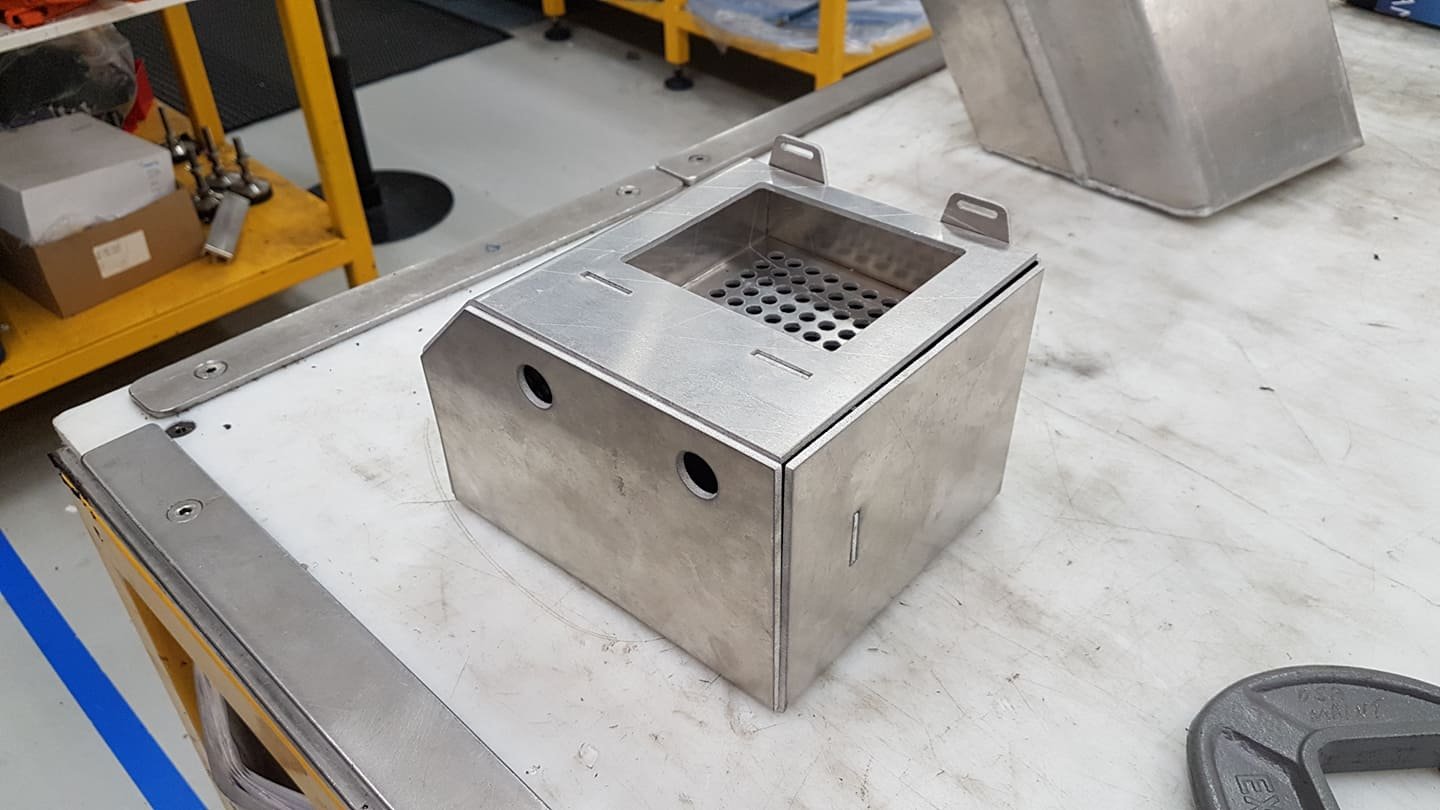
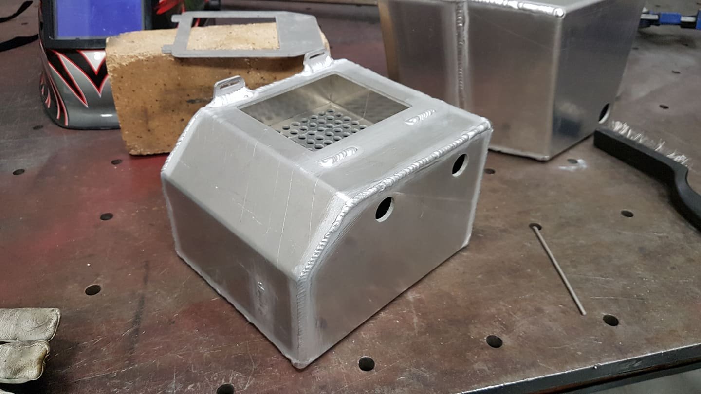
This update has been a very long time coming - just due to life and covid etc. Ages ago I got in contact with a friend of a friend who was willing to help me make an oil catch can and a combined sprayer reservoir and radiator overflow. All the parts cut up: Reservoir/overflow bent and mocked up: He warned me that he was newish to TIG welding, but I'm happy enough with how this came up: There are still a few bits to do on it to get the washer motor and overflow inlet attached, shouldn't be long now. The catch can bent up: And welded: Both items need to be blasted and scotched up, but I'm pretty happy with how things are going. Once these are sorted I can start thinking about starting the panel work in the engine bay!
- 73 replies
-
- 20
-
-

-
Cheers man. Will be keen to have a chat about a few different things that need a cert soon.
-
Looking to do some chassis strengthening up the front of my car. I'll probably buy this kit, or make up my own version. https://www.retrofication.co.uk/338.html Mostly keen on the A pillar gussets and the chassis to bulkhead gussets. Am I going to run to any issues?
-
I probably haven;'t really addressed it. But it is a similar build to the g-series I had in there before. It's just a slightly more modern (barely) engine. Saying that, there is at least one dude in Aussie with a 10.5:1 comp g-series running 35psi or something. So it is doable.
-
With a turbo on an engine designed in 1980?
-
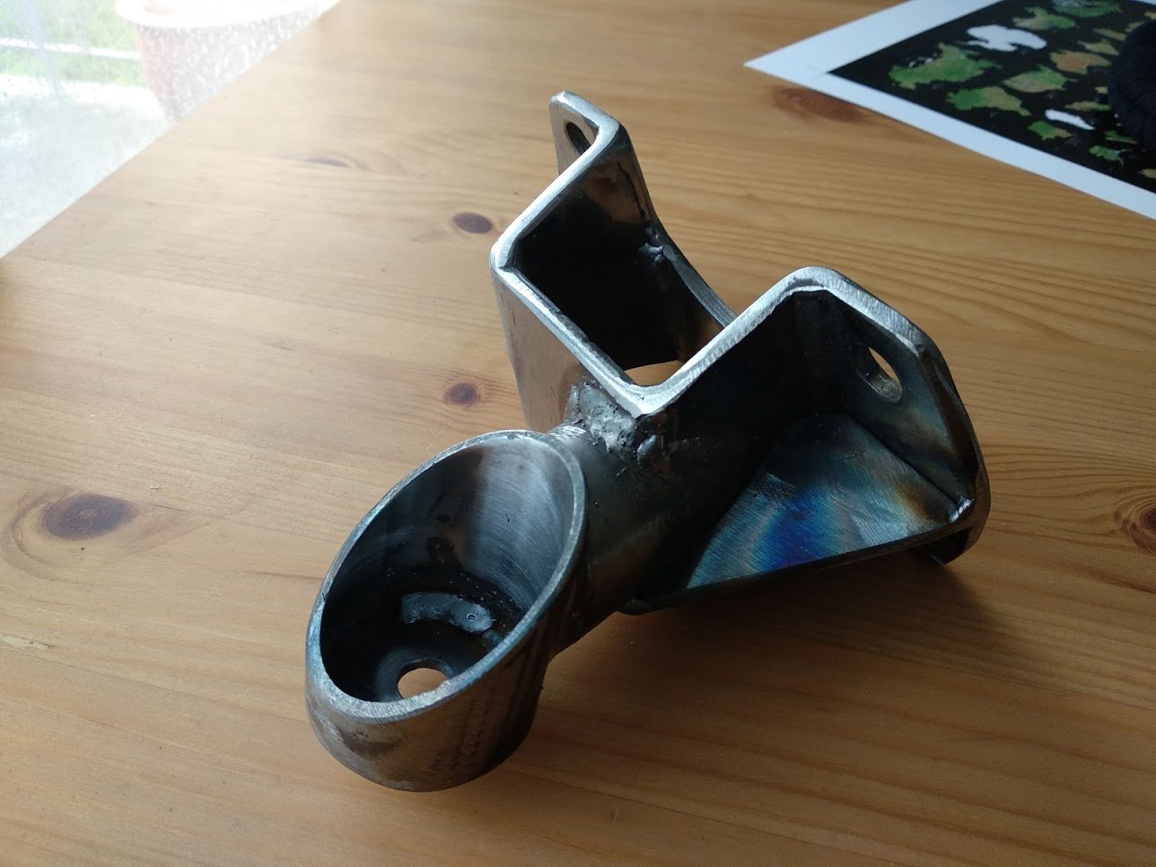
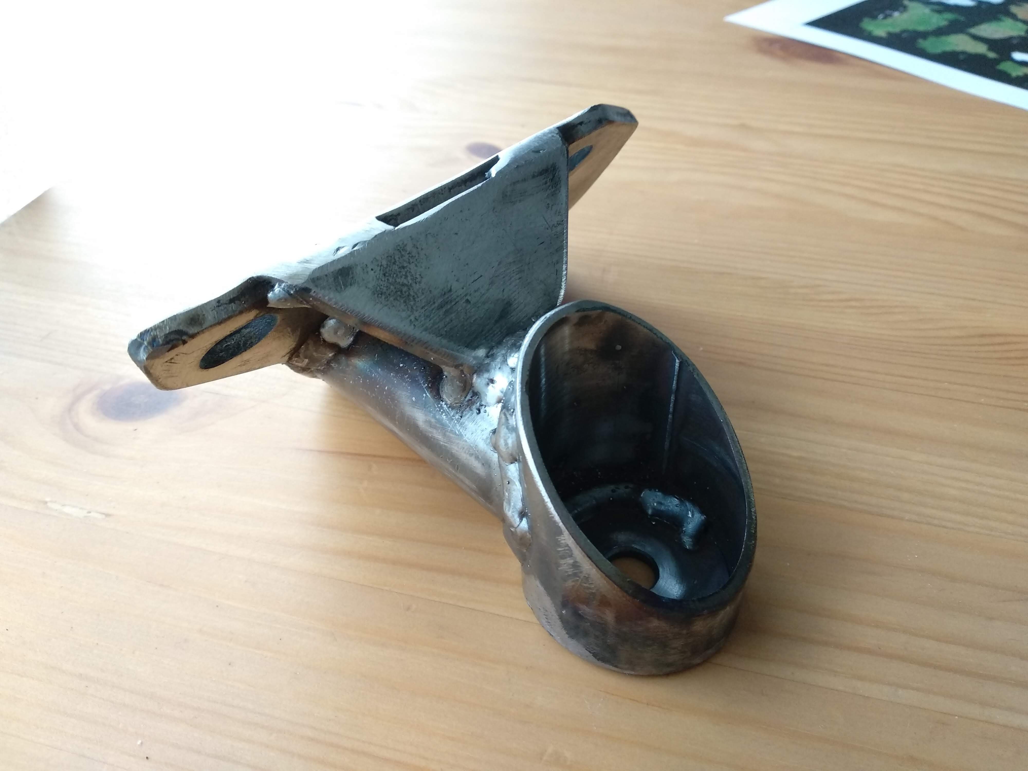
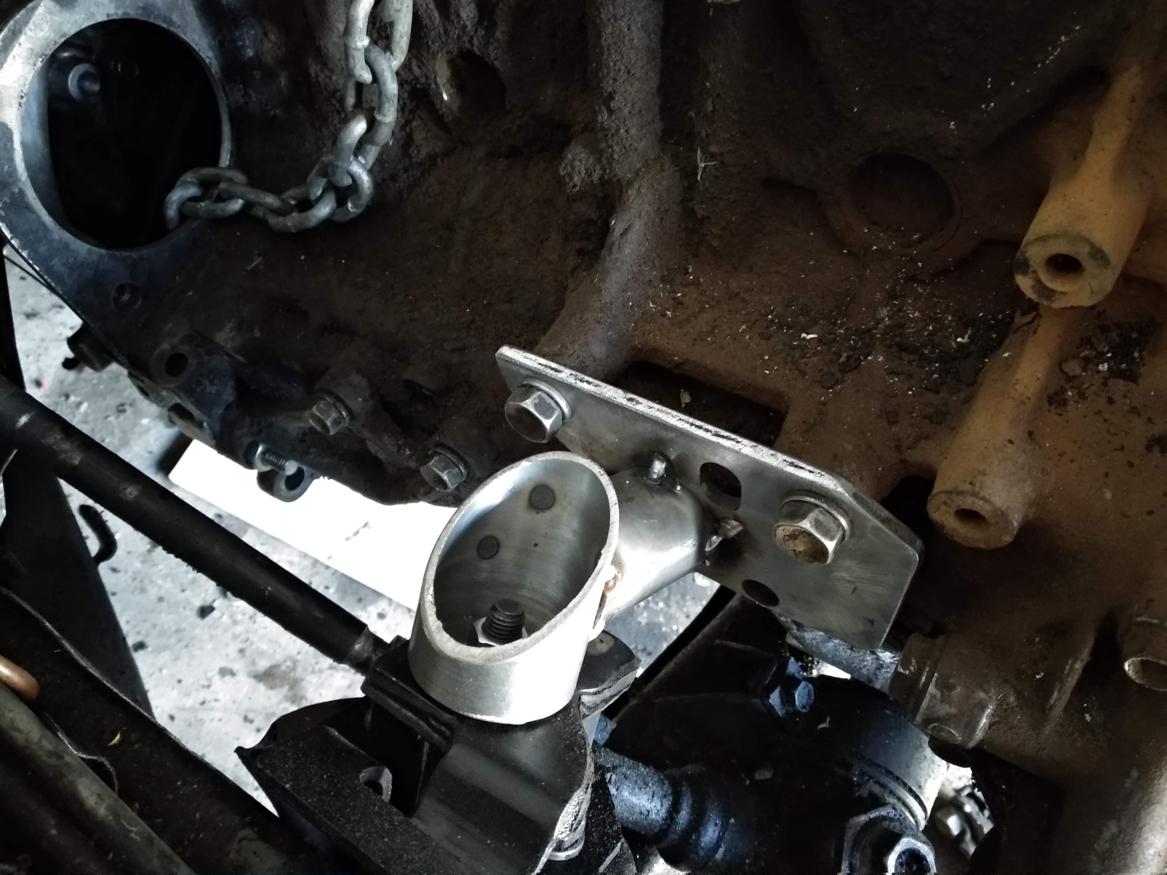
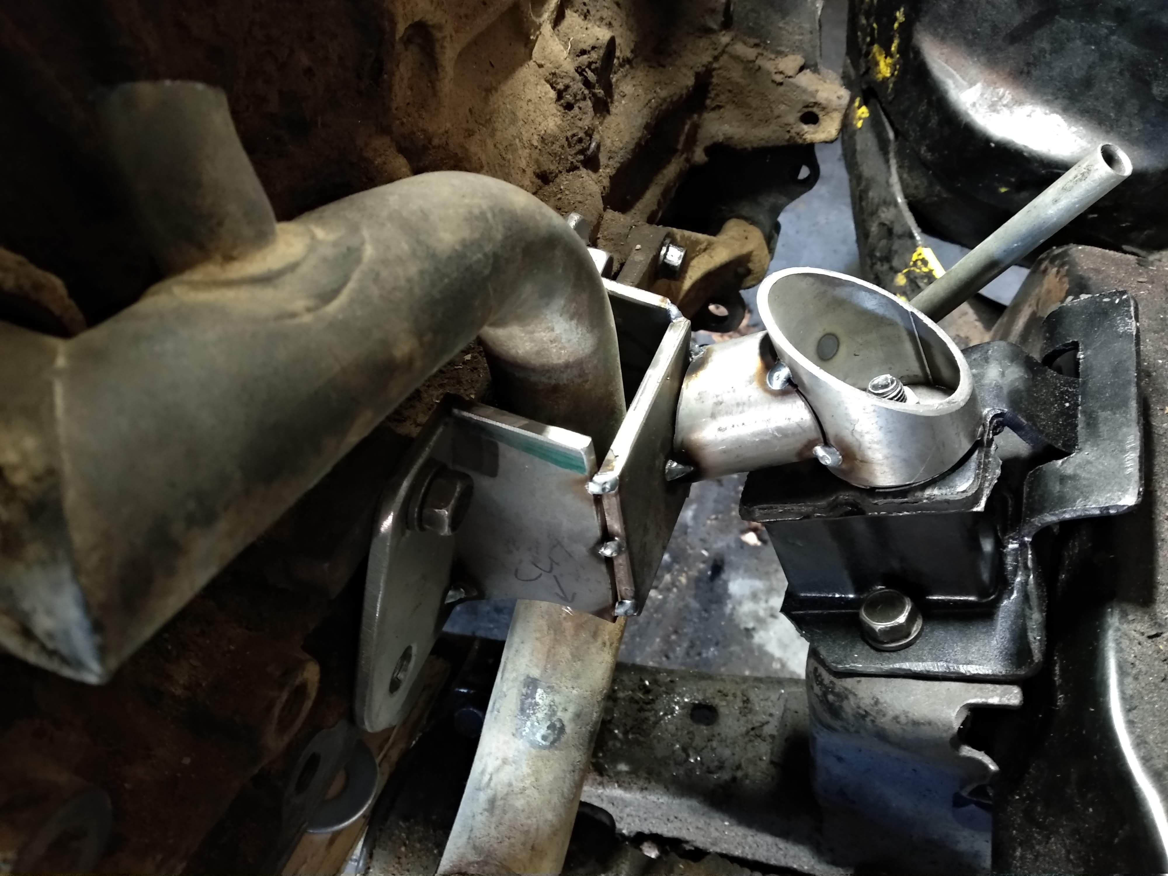
Chris finished welding up the mounts, just need to be cleaned up and coated now. Should be super solid. Now I can get back on to sorting the sump out.
- 73 replies
-
- 14
-
-
Whoops! Yep.
-
Did you ask for real progress? @EURON8 and I (mostly Chris) have got the engine mounts for the D1 tacked up. Chris will weld them up and then I can get back to sorting the sump. At this point I could pretty much have put a better engine in. At least it's still Isuzu? Also, thanks to @Snoozin @Spencer and @Thousand Dollar Supercar for their help with the AE101 brake kits. They turned up this week
- 73 replies
-
- 14
-
-
Cool. Thanks man!
-
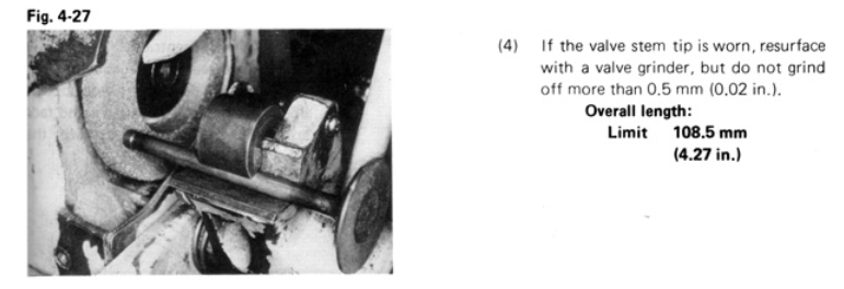
Just to reply to myself further, I found this in a 2T/3T workshop manual. Can I assume from this that the factory length is 109mm? And if so, if the 110mm valves are good on the exhaust, should I go for 109mm or 111.54 on the intake?
-
I wonder if any one reading this knows the factory length of a 2TC/3TC valve stem? I was assuming that they were 110mm based on these, which I've been told will be fine for my head (https://www.speedfactoryracing.net/products/supertech-tivn-1063-supertech-performance-valves-toyota-2tc-3tc-intake-valve-44x8x110mm-ss-backc) But there are all sorts of other aftermarket valves with different lengths. Basically I'm trying to find out what "factory length" means for these valves: https://www.euroexportinc.com/toyota-3tc-2tc-45mm-stainless-steel-intake-valve-set/ If it's 110mm then I'm good to go.
-
Thanks for the offer but I think I'll be okay. I have a head and also you can buy new ones still, so if I mess this one up I should be okay!
-
Hopefully I don't need to cut anything then! That could be an decent option too.