

PedRac3r
-
Posts
87 -
Joined
-
Last visited
Posts posted by PedRac3r
-
-
Looks good dude. Good call on shifting that engine back.
-
Here is the fuel pump cradle, complete with a sealed electrical bulk head from MSEL.

Here it is installed in the tank through the cut out I made in the floor. Makes it a lot easier to work on, means I dont have to drop the entire tank just to get to the lift pump.
Added some -6 bulk head fittings. Fuel in from lift pump, surge tank overflow, fuel rail return and fuel out from the Bosch 044 pump. Had to make some 3mm thick aluminium washers as the sheet metal was too thin for the bulk head nut to do up tight.
I had my mate Graeme at SMS fabrication tune me up a surge tank that I drew up for him. He's got all the gear to cut and fold sheet metal, and hes a bit of a whiz on the TIG welder when it comes to aluminium. Here it is mocked up.
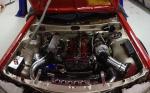
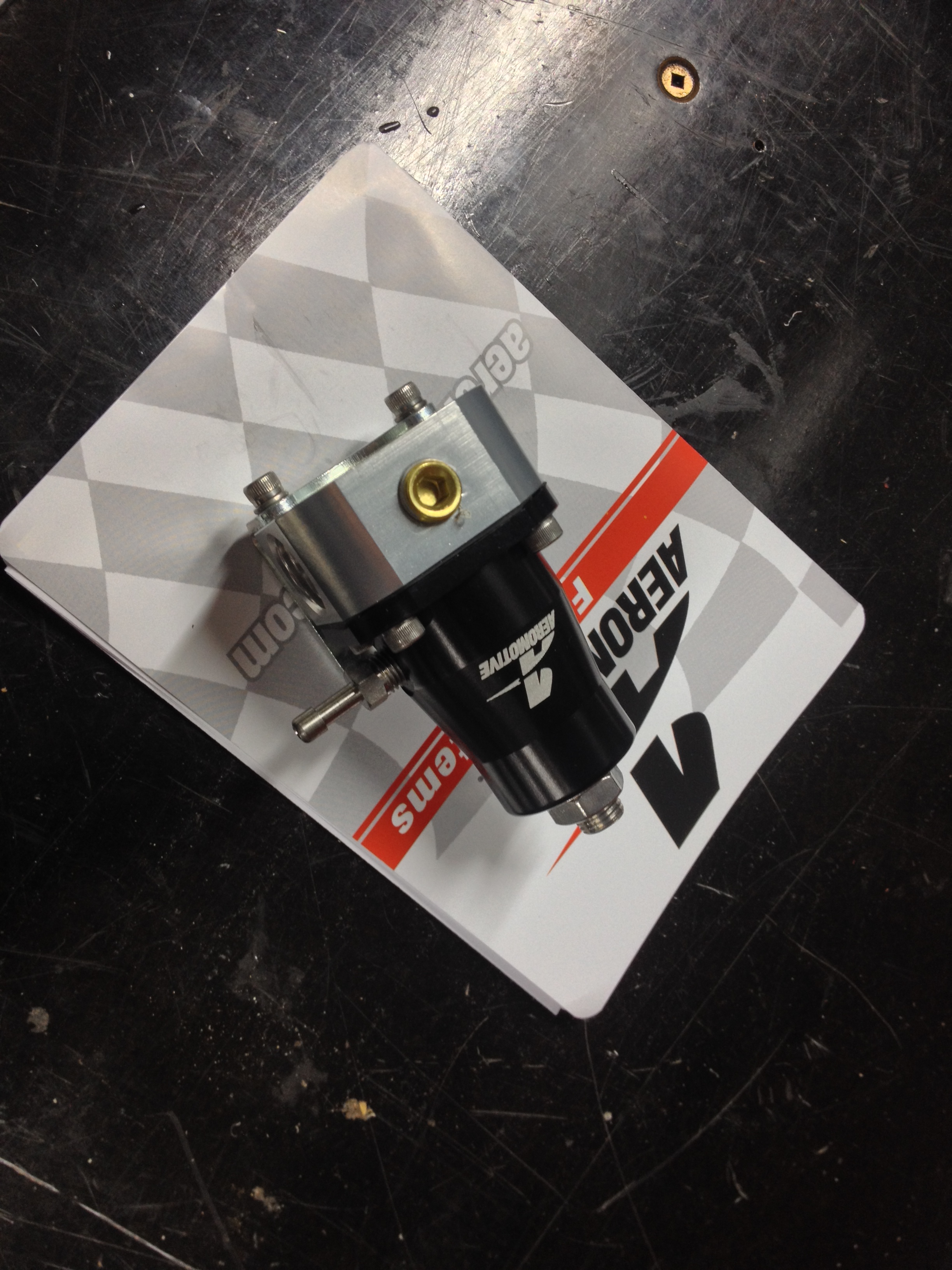
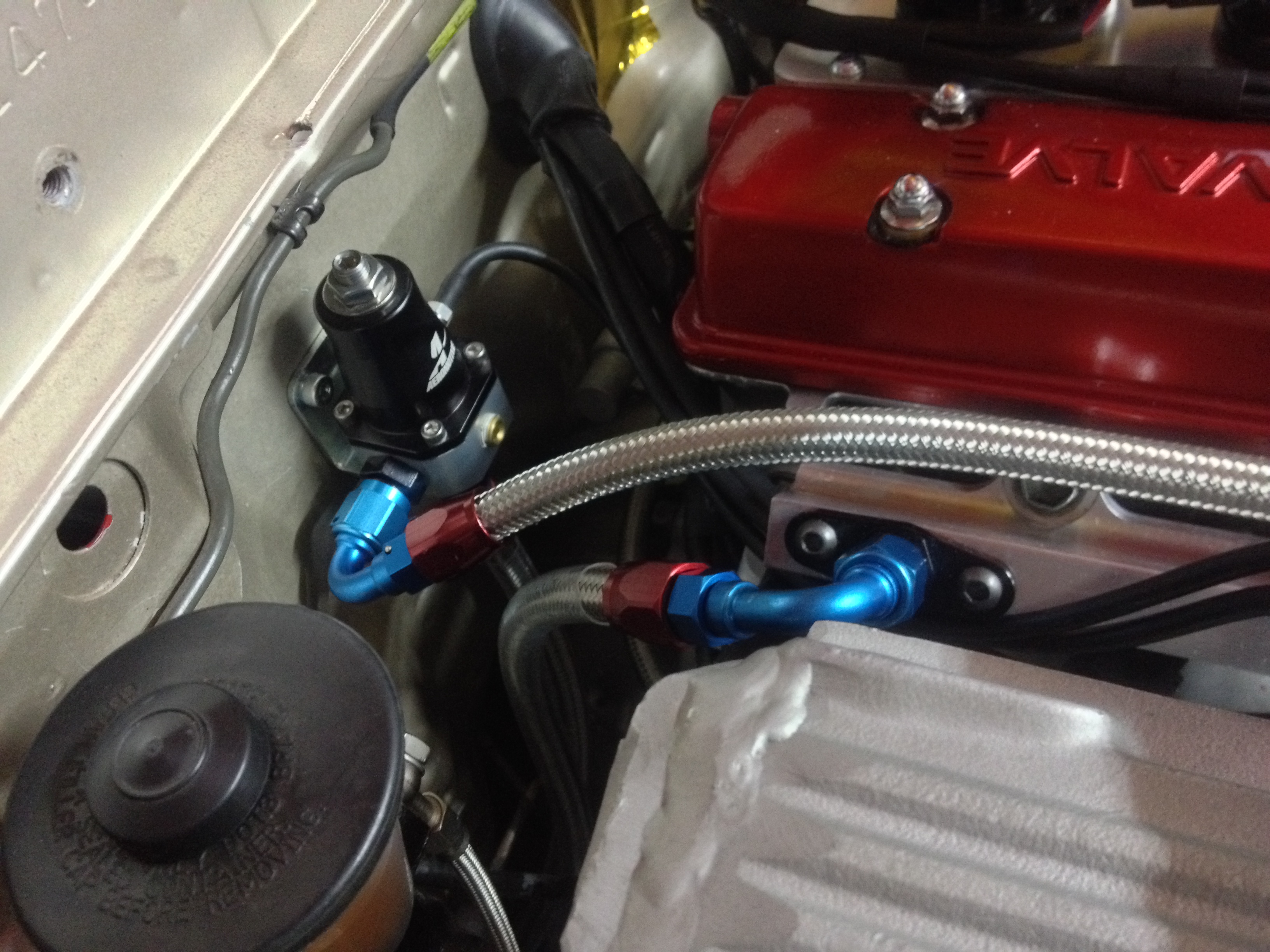
Brought an Aeromotive fuel regulator, mounted that on the fire wall. Made a few changes to the fuel rail to make it easier to make up the fuel lines. Decided to go with braided lines through out, although a little more expensive it was going to be easier to plumb up and make it alot simplier.
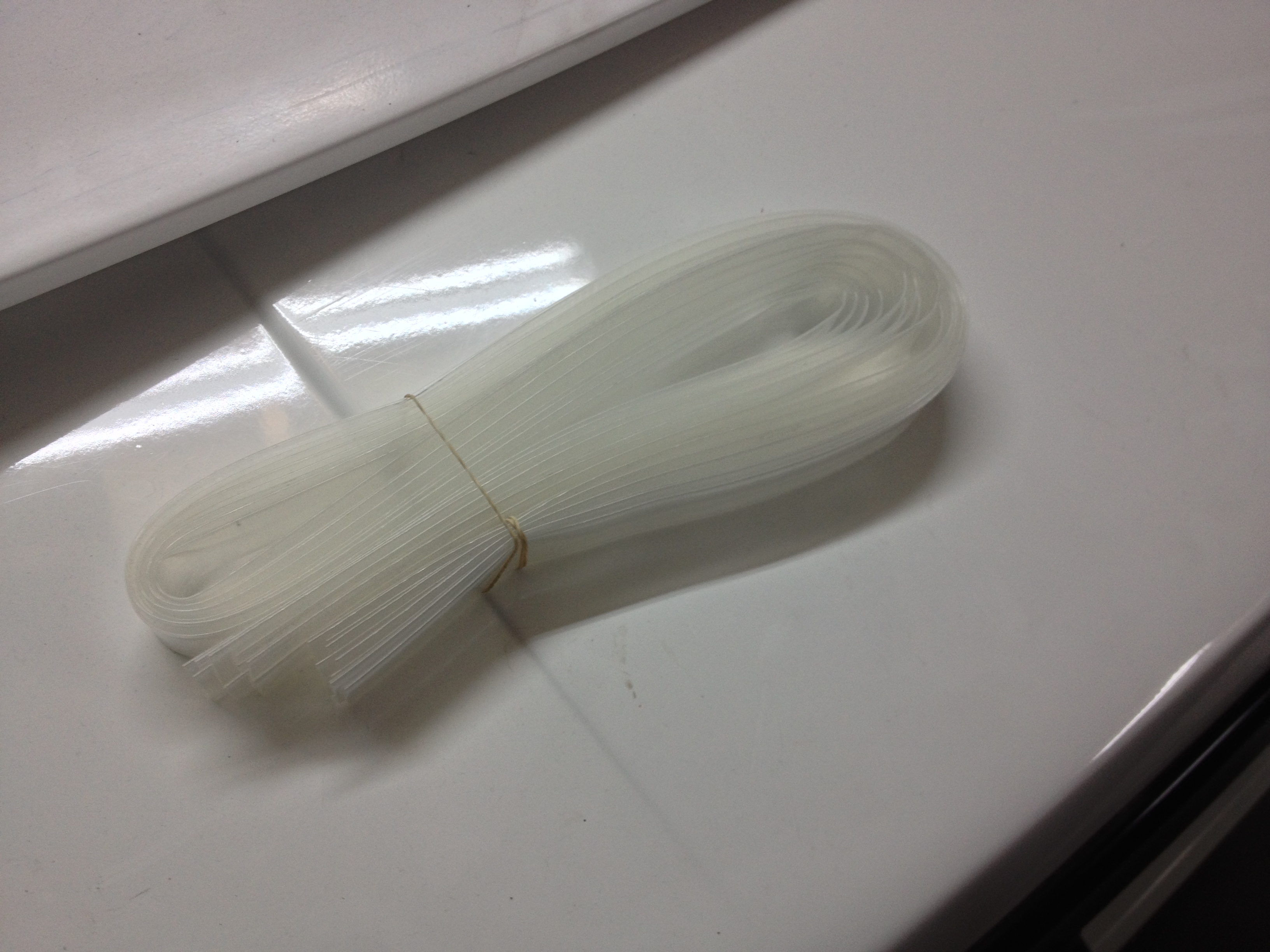
With the fuel rail back on, regulator mounted and bulk heads to the surge tank fitted I started to make up the main and return fuel lines so I could get the car back on the ground. I wanted the fuel lines to hug the underneath as much as possible, but with the stainless braided being quite abrasive I was worried that it would rub on the steel causing all sorts of shit. I ended up ordering 10m of 20mm clear heat shrink to cover the fuel lines to act as an insulator.
Hard to tell from the picture below, but the lines have been covered in the heat shrink.
Underside and engine bay side of things were all sorted, dropped the car back on the ground and began working in the boot to finish it off. Purchased a rivnut gun to mount the tank and fuel pump as well as the block off plate. With those mounted I could make up the remaining fuel lines, so after mocking a few lines up and getting an idea of what fittings I needed to purchase, it was done!
Primed up the surge tank and checked for any leaks, which there were none, so plugged the Bosch 044 pump in and checked for any leaks in that circuit, which there was, and see where the fuel pressure was set at. I had to tighten one fitting a touch more, and replace a copper washer on the fuel rail. No leaks, but the fuel pressure was still at 5 bar (what the reg was set to out of the box, atleast I know it can handle 5 bar!) so I dropped that down to 3bar.
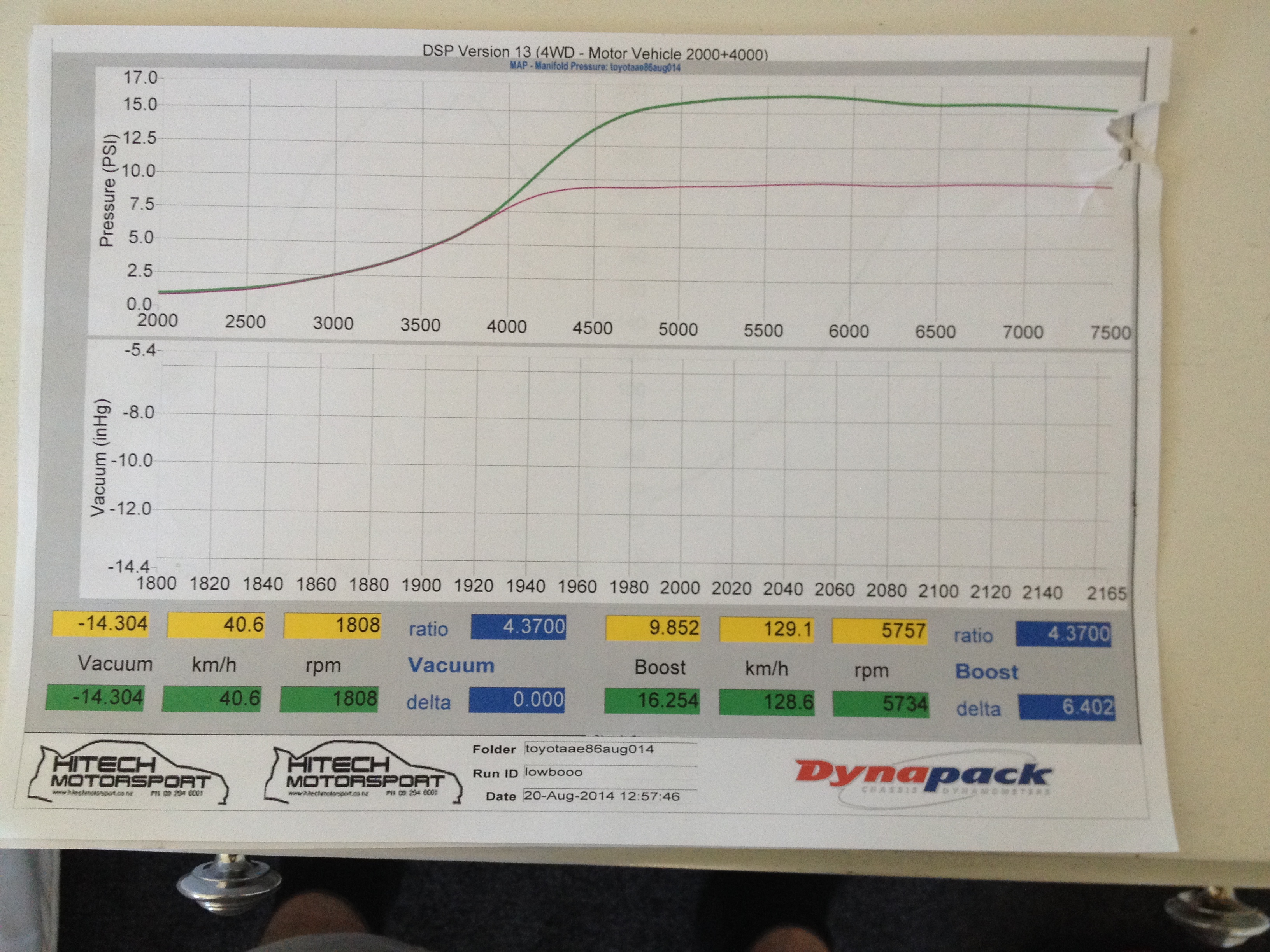
So a few weeks later it went out to Hitech Motorsport again to have the engine tuned on the Link Atom G4+. Got them to setup 2 boost maps to switch between, low boost is 9psi, and high is 16psi. Green line is high boost and pink is the low.
Power curve gets a little peaky on the high boost map after 6500 compared to the low boost which holds the power right through to 7500. Could be to do with the boost dropping a 1psi or so up there, or maybe turbo inefficiency? Still plenty of power though! Probably need one of those fancy new billet comp wheel turbos to spool things up quicker. Saying that, and even though boost graph looks dull, it doesn't feel like there is any lag. You can put your foot down in any gear and it will pull hard, and the power curve definitely confirms that.
-
 7
7
-
-
So exhaust done, I had to finish of the changes on the hot side of the I/C piping. I machined up another one of these adaptors
This rotates the intercooler elbow that bolts to the compressor housing 60 degrees, so that it points to the front of the car, instead into the manifold or strut tower. Welded a boss on to said elbow, added a 90 deg hose barb for a pressure signal to the wastegate.
Bolted it up to the adaptor I machined earlier and fitted it on the turbo, which meant I could finish installing all the hose joiners and clamps. Ditched all the blue joiners and went for black stuff, also went to an 3" intake pipe instead of the 2.5" I was using previously.
With that done it means its pretty much all sorted, except I decided to relocate the boost control solenoid to reduce the length of the lines. Oh and because race car, I made a racing light weight race pipe for racing because race car loud race pipe tip... yeah.
Basically just a 3" tip, I put a V-band on it so I can swap back to the muffler if noise became an issue (which it was)
With everything back together and ready to go on the dyno again, in typical fashion, I decided to pull some more shit off it so it wasnt going haha. The AE85 fuel tank has always been a pain, from mounting the fuel pump, to the lack of baffling and the surge you get below half a tank of gas... Made the decision to finally sort this out by putting a proper surge tank setup in it. Bought a Bosch 044 and a 10 micron Aeromotive filter from NZ Performance. Always a pleasure dealing with them!
So after talking with NZEFI about whether I'd be able to use the Bosch 044 on the same electrical circuit as the DW300 pump (which shares with the ignition), we came to the conclusion that I would be pushing the current draw to high, and also the fact the DW300 pump wouldnt be suitable as a lift pump I purchased a low pressure lift pump to replace the DW300. The good thing about this lift pump is that it only draws 1amp, so it drops the current draw to much more suitable level. NZEFI have been really helpful with any questions and queries Ive had since purchasing the Link G4+ Atom from them.
Pulled the tank out to drop the new lift pump in, and I could see a fair amount of sediment in there, aswell as really small fragments of what looked like rust in the DW300 filter sock... Not something I want going through my new pumps or injectors! 15mins researching of how to clean a fuel tank and I found that hydrochloric acid was recommended, which was good as I had 15-20L of this. So stripped the old paint off the outside of the tank, filled the tank up with hydrochloric acid diluted with water. For anyone doing this at home, make sure you're wearing suitable protective gear, dont want to get any of this stuff on your skin or breathe in the fumes! Let the acid do its thing for a few hours, added some baking soda and let it sit for a bit then drained it, then filled it back up with water and a few cups of baking soda to further neutralise the acid. After draining that, the tank basically looked like new inside, stoked! I filled it back up again with water and some "Super Ripper" cleaner, let that soak to remove anything left behind and went through a lengthy drying process which involved pumping hot air through it with a heat gun. With inside clean I masked off the holes and removed any rust on the outside, painted it with a rust kill etch primer and then finished it in satin black.
I just needed to get the lift pump in there now, but I was sick of staring at this old fuel pump cradle...
Soooooo I made a new one. Machined up a few pieces and welded the lot together, added some Fragola -6 adaptors so I can run braided line from the tank to surge and vice versa.
Ill leave it here for now
-
5
-
-
Oxy sensor thread is M18x1.5. Can get bungs from Chase Exhaust, Pitstop, Trademe etc. When I bought my Innovate wideband it came with the socket and bung. What G4+ ECU are you using, Storm?
-
1
-
-
Awesome work guys. You can never have a shed too big!
-
- Popular Post
- Popular Post
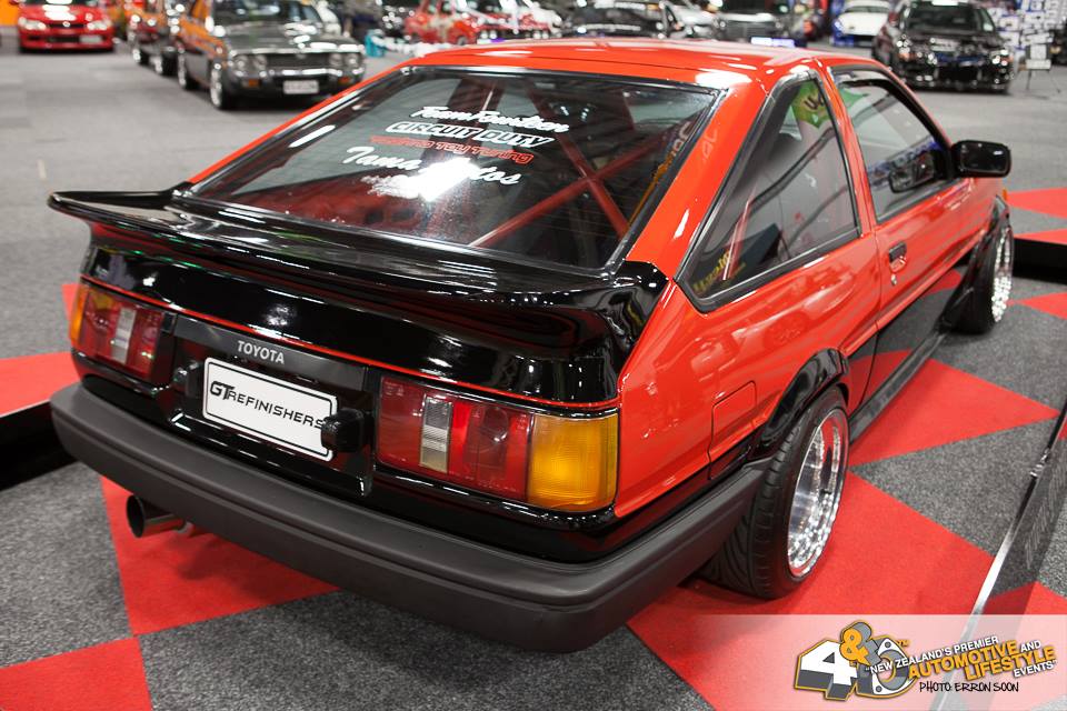
Grant from GT Refinishers asked if I would have my car in his stand for the 4nR nationals, engine was back in and going through the running in process so I figured why not. Turns out the judges deemed it worthy enough to award me the Best Toyota trophy. Here's few photos from the 4 and Rotary Show and Shine
With the car back home, and the running in process almost done after a couple open days at Pukekohe, I decided there was a few things I was gonna change before it went for its final tune. Picked up a new steering wheel (obviously doesnt effect the tune but trying to keep a constant timeline happening) to replace the bent 330mm wheel. 330mm always felt a little too small so went with a 350mm dia 90mm offset wheel from Velo so its all matchy matchy with the harnesses.
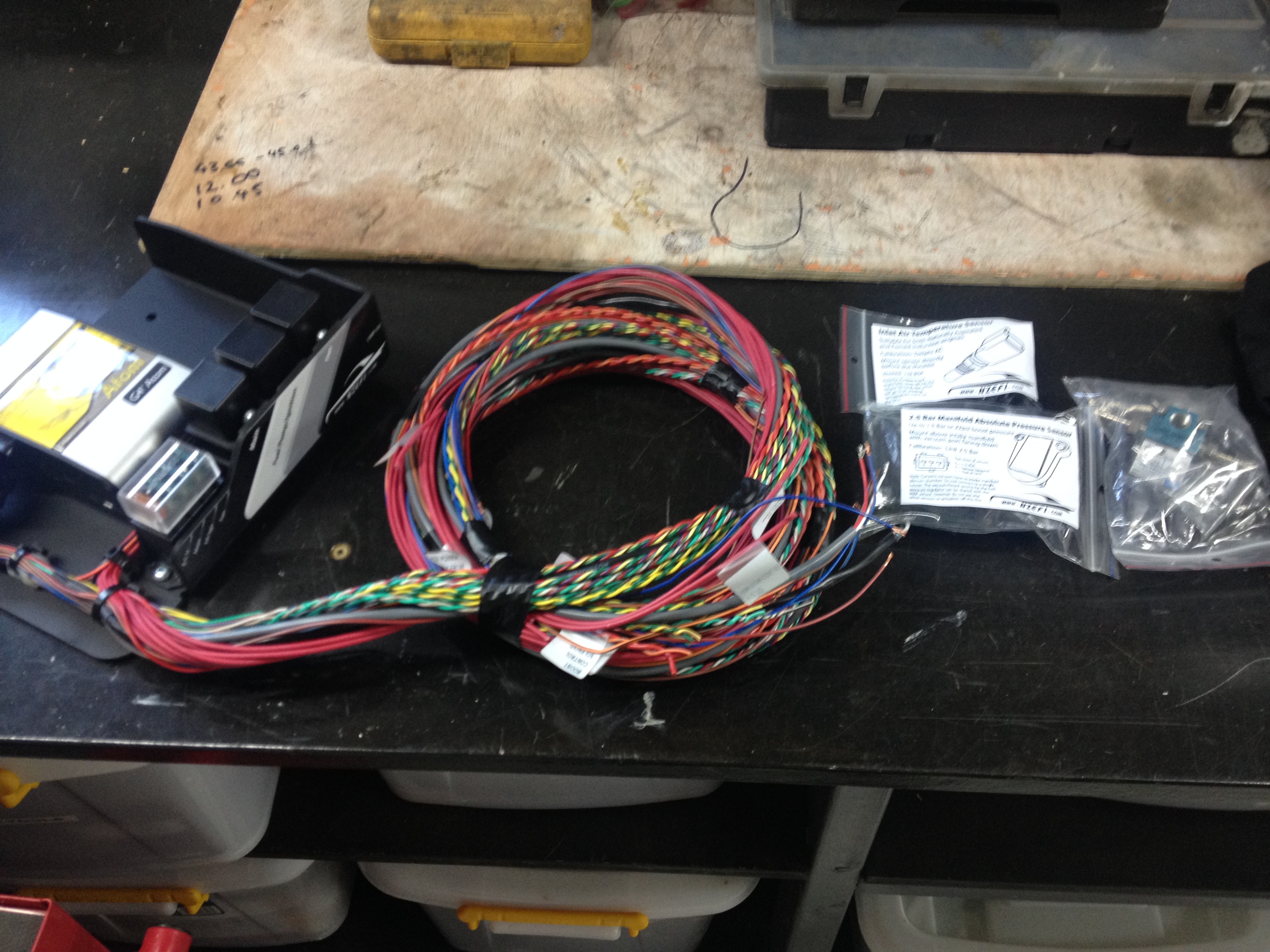
Bought a new G4+ Atom ECU and NZEFI wiring kit/bracket. While there was nothing wrong with the G1 ECU, figured it was time for some new technology and now was the time to do it seeing as I will need to retune the engine since the rebuild.
Got a 2.5bar MAP sensor, Bosch IAT sensor and a boost control solenoid also. The NZEFI mounting bracket is a neat bit of kit, Id say its worth paying the extra few dollars to have all the relays and fuses already wired, sensor wires twisted and labeled, makes the installation that much neater and easier.
I really wanted to go for a full Mil-Spec loom with all the fancy Autosport connectors and Raychem DR-25 heat shrink, but after pricing up a few of the items, it was going to cost me what I spent on the ECU alone... So went for Mil-Spec "inspired" loom instead, seeing as none of the automotive plugs Id be using for injectors, coils etc arent up to MIL spec anyway. Put an order through Jaycar for a few metres of each size of their heatshrink (seems to be the better stuff without breaking the bank), along with some switches and crimping pliers.
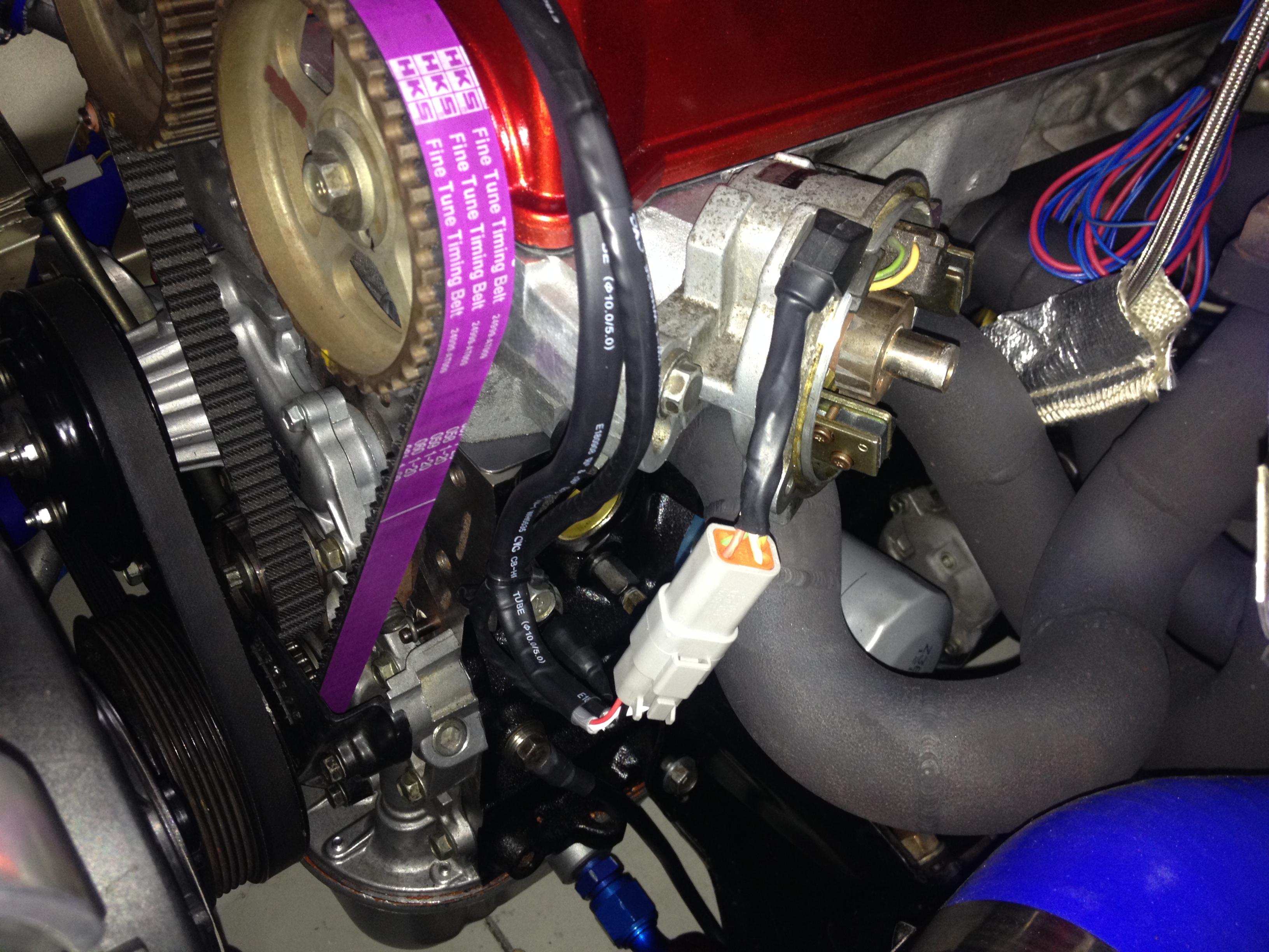
Coolant temp sensors, Injectors, TPS, IAT sensor all done, with just the CAS and coil wiring that need to be finished off to complete the engine bay side of things. Also picked up some 1NZFE coils to replace the dated distributor setup.
Purchased a bunch of Deutsch connectors for various things, mostly so I didnt have to cut and solder old plugs back on etc, and to make the engine and chassis loom independent of each other, something that always bugged me was not being able to remove a section of wiring without having to remove everything. DT 4 way connector terminated to the CAS and trigger wiring.
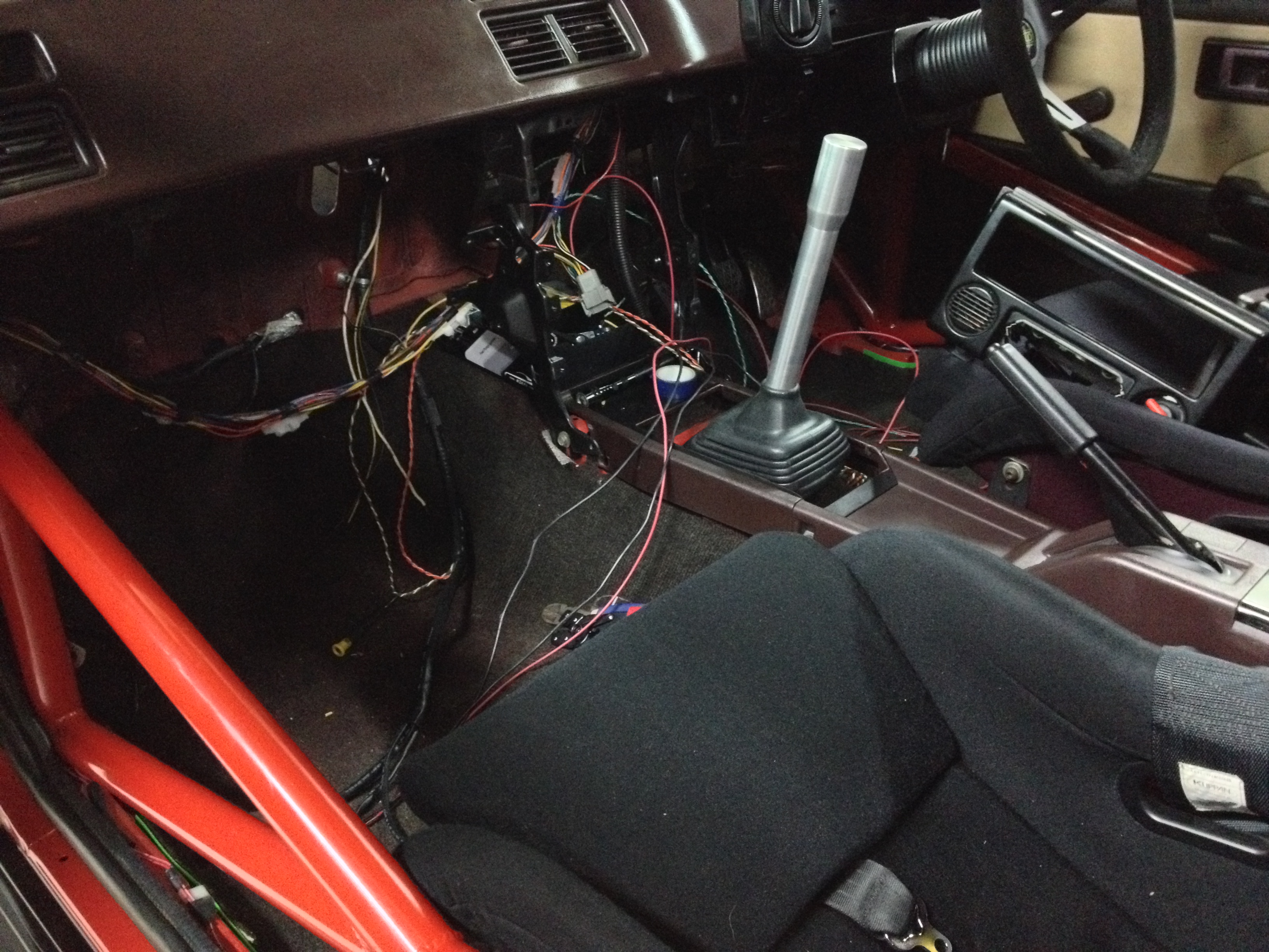
Also in the picture are the sensor grounds and oil pressure sender which makes the engine side of things complete minus the coil wiring which I was still waiting for connectors to finish. Moving to the interior, it has been looking like a bit of a mess lately with wires going everywhere.
Here are a few more of the Deutsch connectors on the chassis side of the engine loom. You can see one of the mating connectors in the background. These have the fuel pump/fan wiring, dash sensors, boost switch, ECU supply etc going through them.
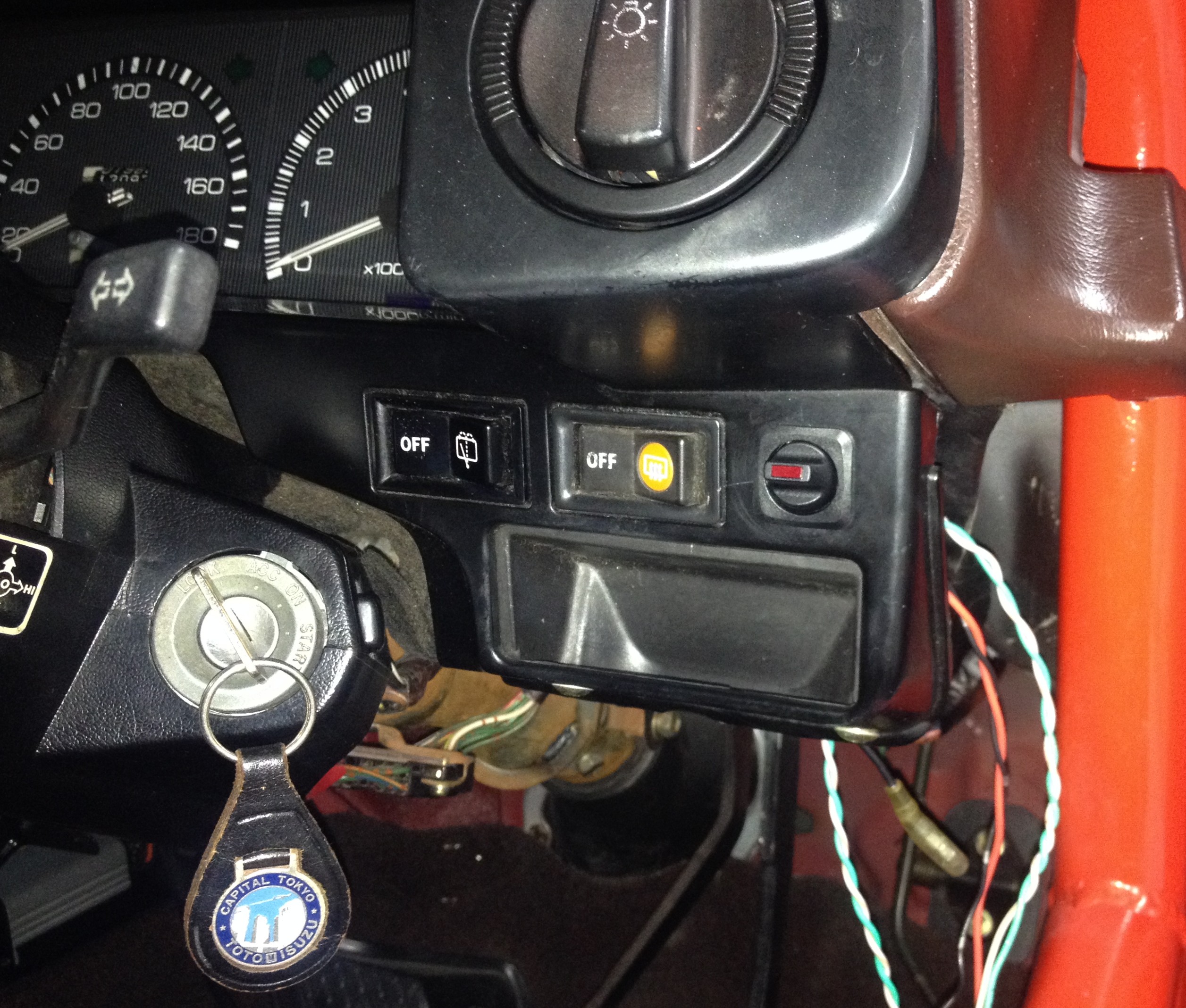
Got this neat little switch from Jaycar, illuminates red when switched on. This will be used for activating the boost control solenoid to switch between high and low boost. There was already a switch mounted there so I used that hole rather drill another, I think it was originally for the fuel pump when I first brought the car.
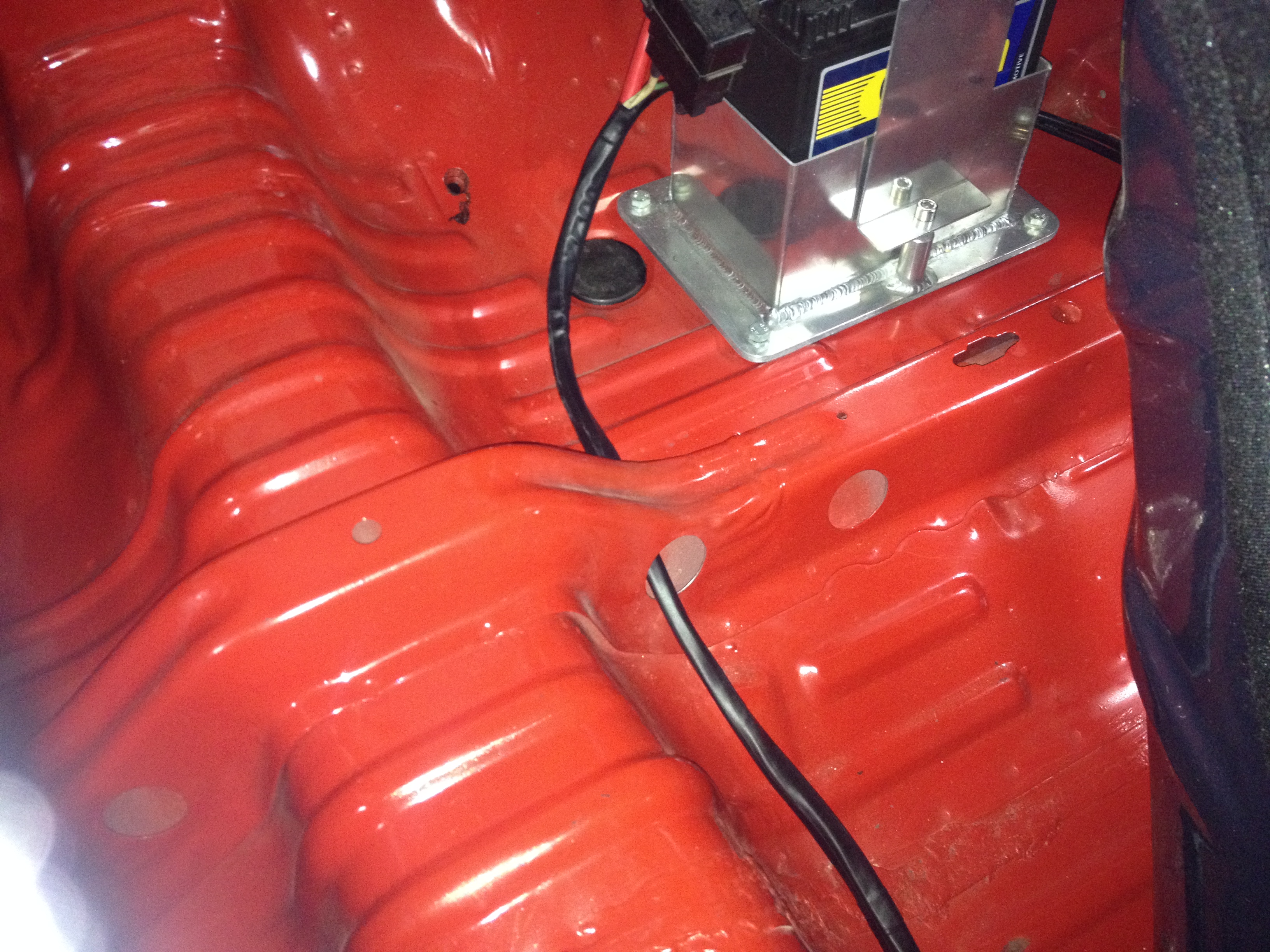
Also when I bought the car a few years back now, it had an Isolation switch mounted in the dash like this pretty much. I removed it when I re-routed the power wiring because it wasnt installed properly, so alot of the electrics still worked with it off... Ended up putting it back in, as I can have my main battery wire attached to one side, with the starter, alternator and chassis power wires on the other terminal so it should work as it suppose to, and eliminates the use for a distribution block to feed power where it needs to go.
Tidied up the battery wiring a little with some heat shrink instead of the split corrugated tubing.
The coil pack plate and distributor blanking cap arrived, spent a few minutes and got those installed.
Got all the wiring done for the ECU, but I left it disconnected and started to check through all the chassis wiring making sure all my lights and wipers etc still worked. I did have an issue where the head lights have been intermittent and I have had no dash lights aswell. Started at the headlights working my way back checking all the components, and after several hours of fault finding I had found nothing out of the ordinary and I was only left with the switch on the dash to check. Grabbed the light switch out of my brothers Notchback and plugged it in mine... Sure enough everything worked as it should. So pulled my light switch apart to find some broken solder joints, easy fix with the soldering iron, was pretty stoked to have all that working again!Started running the G4+ Atom through the configuration. The ECU has a feature to test all your circuits to make sure they work before the first start up, so went through that and seems my wiring was spot on as the fuel pump, fan, injectors, coil packs, boost solenoid etc all works perfectly. So with the new ECU all wired up and working, but still yet to start the engine, there was a couple more things I decided I could do before the tune... My brother had decided he would turbo his Notchback Levin, I figured he could have my old turbo manifold and Ill fabricate a new one for myself. As usual, started to take some pictures at the beginning, got involved and forgot to take any more. Here is the start of the merge collector after the first cut on each tube.
After that, I tacked a pair of the tubes together as above, and made another cut, then tacked the pairs together to form the merge collector. This one has a nice shallow angle for a smooth merge into the turbo. Several hours later I had 3 runners tacked up, all equal length, with just cylinder 1 to finish.
Looking back at this now, I should have had the runners enter the collector in firing order, but it was going to be a little more difficult having to overlap runners and still clear everything, and I really liked the almost symetrical look. Anybody done any back to back testing with merge collectors to see if entering the collector in firing order matters or not? Anyway, I've positioned the turbo in a better place with this manifold. I originally made the first manifold for the T25 turbo, but with the T28 being a little bit bigger it ended up sitting up higher and closer to the strut tower than I wanted, so I have dropped it down about 45mm, moved it forwards and away from the strut tower 20mm.
Finished off tacking up the last runner, machined up a new flange as that one on the manifold I basically just use for setting up so I can tack and cut as I need to without worrying about cutting into the flange with the grinder etc.
Same deal as the last one with the 30 to 35mm port taper and a 1mm recess which makes locating the runners concentric with the ports a lot easier. Added a 2 braces between the runners and collector, aswell as the wastegate port and flange and then finished in the same high temp flat black Dulux paint. Seems to be the best paint out of all the VHT and other "high temp" paints I have used.
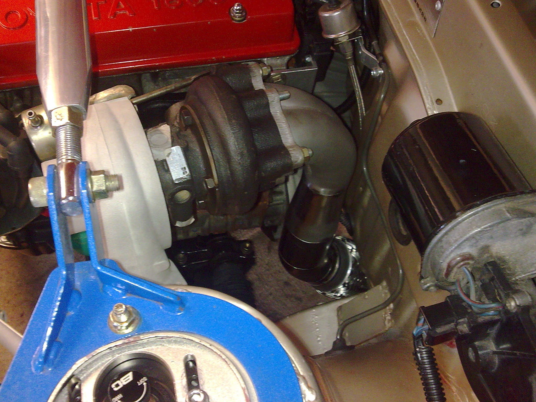
Got the turbo bolted on with new studs and lock nuts, but something I had been fearing for a while had finally become a reality... There are 3 bolts and 2 studs which seal the exhaust manifold to the head, and since Ive owned the car, 2 of the holes/threads in the head have been a little iffy and Ive always taken extra care to do them up. When bolting this new manifold up, they've finally given up and wiped the thread out completely, which was gut wrenching. Purchased a Helicoil kit from Trade Tools, they're not cheap as I found out, but everything worked out perfectly in the end. Was pretty stoked!
With the manifold and turbo now bolted up for good, I made the wastegate pipe. Ended up being pretty funky!
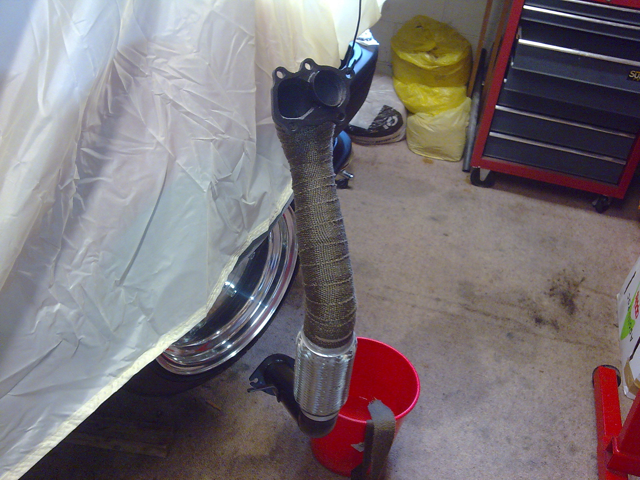
Fabbed up a new down pipe, pretty much the same as the old one which my brother is going to be using, just a few different bojangles as I cut and rewelded a section of the down pipe to make room for the wastegate pipe.
Machined up an o2 bung, welded it onto the bottom of the down pipe, and said cut and welded section.
That basically wraps up the exhaust side of things, just need to make a few changes to the intercooler piping on the turbo side.
-
11
-
Cheers guys! www.2eight6.wordpress.com, hasnt been updated in a while, but have a heap of things to add. Yeah brother still has his notchback. Made quite a few changes to that too, its also running turbo 4AG aswell.
-
Pretty much building a trophy truck... haha.
-
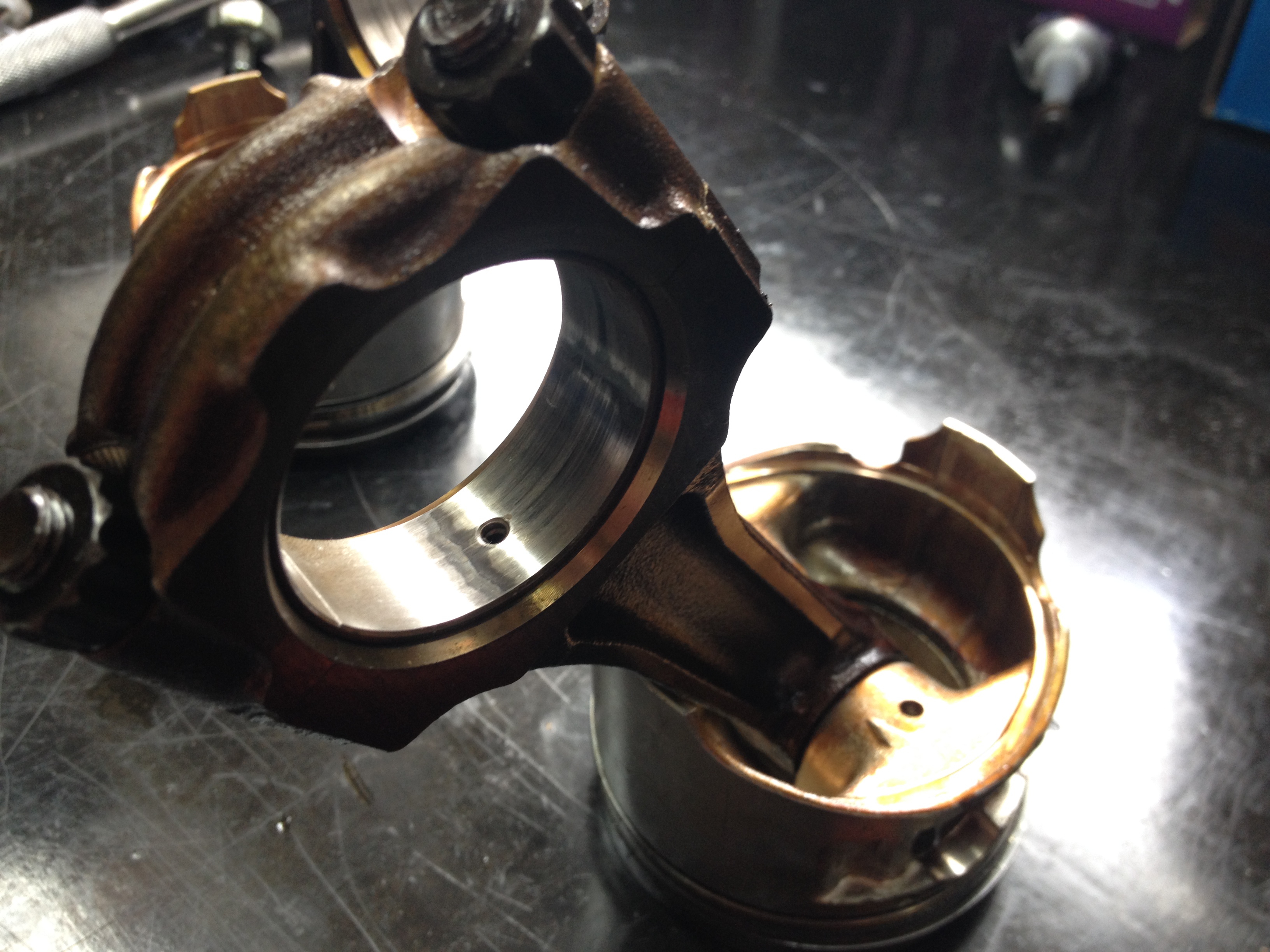
So a few posts back I made a comment about the engine sounding a bit noisy. So after pulling it down this is what we found.
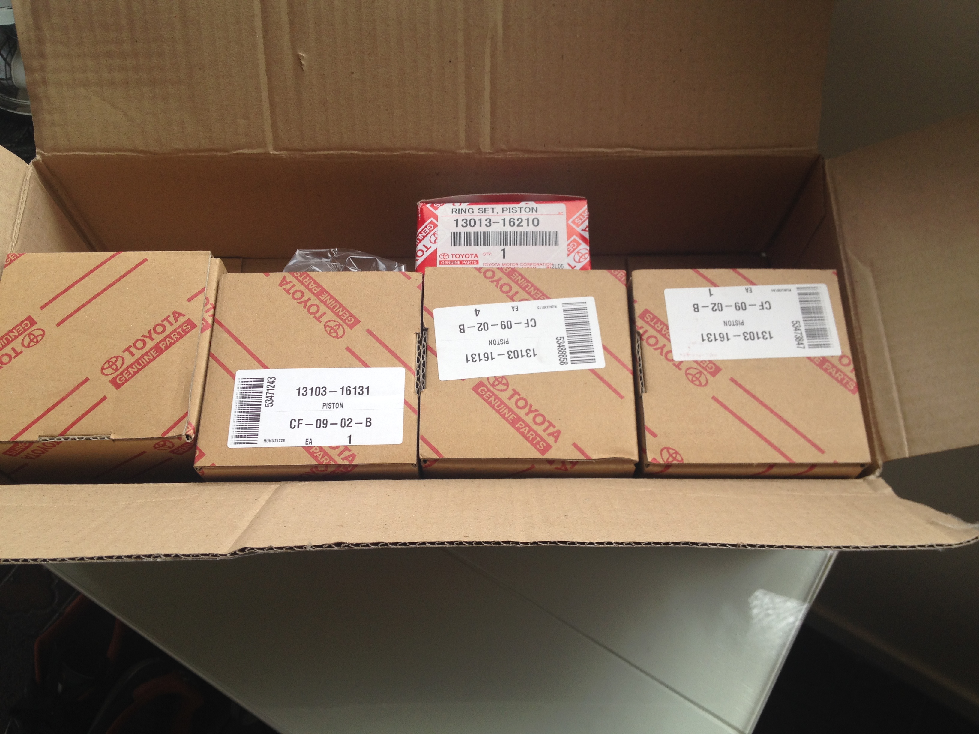
All four top shells on the rod bearings were like that. Not incredibly worn, but enough to open up the clearances and make some noise. So the rebuild began, I let the guys at GER take care of that for me. We went with .5mm O/S 4AGZE pistons, MRP forged H-Beam rods, ACL Race main and big end bearings, ARP main, head and rod bolts, 1mm MLS Toda head gasket and Toda valve springs, tidied up the intake and exhaust ports a little. I hopefully have a fairly solid and reliable engine now
On to the head work I did. Didnt go crazy with it, basically cleaned up the factory casting/machining misalignment and flaws.
Before:
You can see the misalignment between the casting for the actual port and where the valve seat/guide have been machined here on the intake port, probably about a 1.5mm step you can see there.
Exhaust ports were a lot better, apart from the port floor radius into the valve seat being very sharp, almost a bottle neck. Little bit hard to see due to the carbon residue and angle
Also noticed after poking around the head and having a bit of a look, that there were a lot of burrs and casting flaws around the valve train area, and majority of them would fall off if you gave them a scratch with your finger nail leaving small pieces of metal to fall back into the sump. So I deburred the lot, didnt want to run the risk of that happening.
Intake and exhaust port bowls done, as well as removing the shroud around the valve seats in the combustion chamber. Only did the valve bowl area for the intake and left the rest of the port as is. Exhaust port I polished as much as I could, although couldnt quite get in around the valve guide.
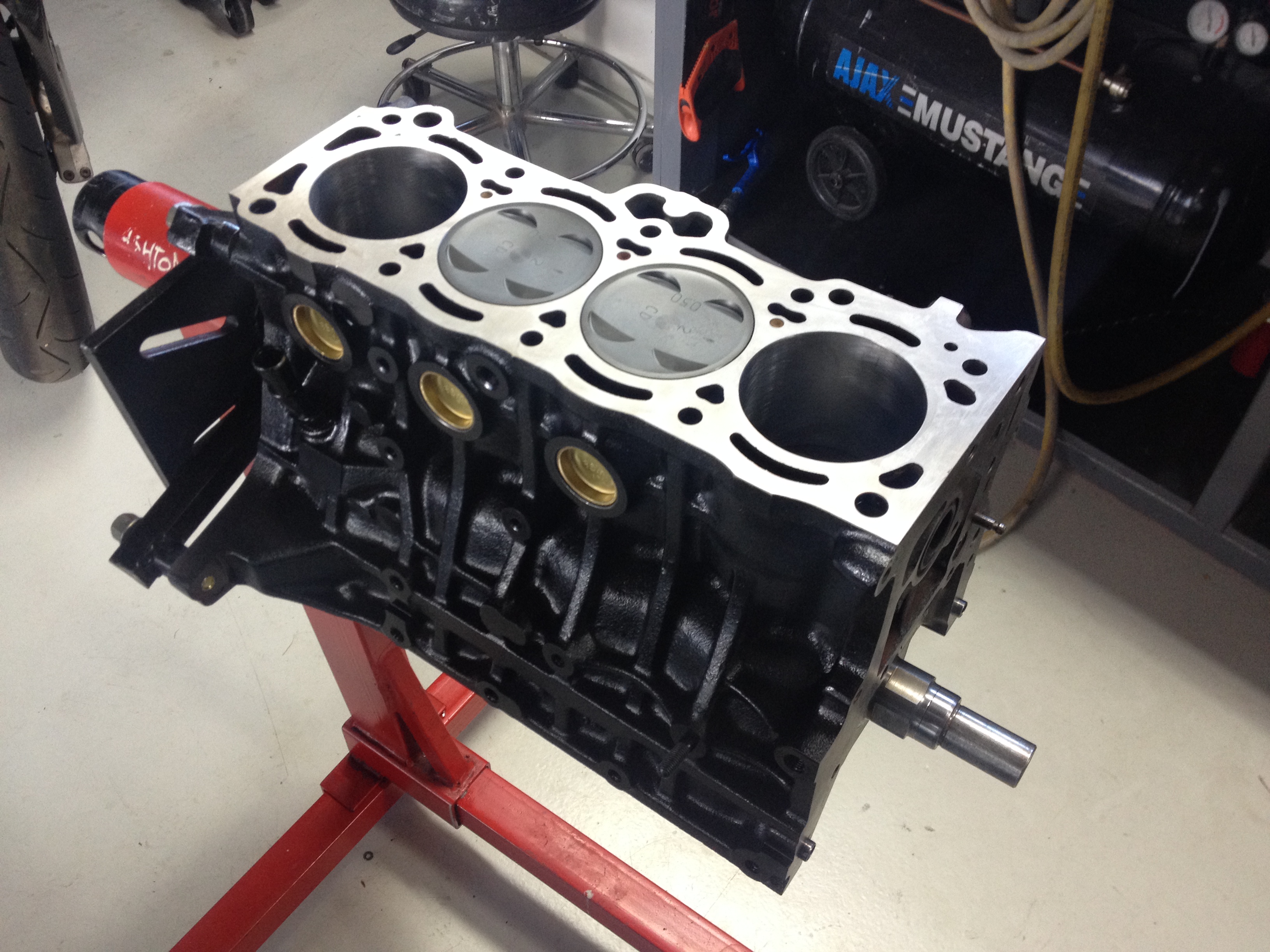
The guys at GER had the block and head ready to pick up.
ARP head studs in, Toda 1 MLS head gasket
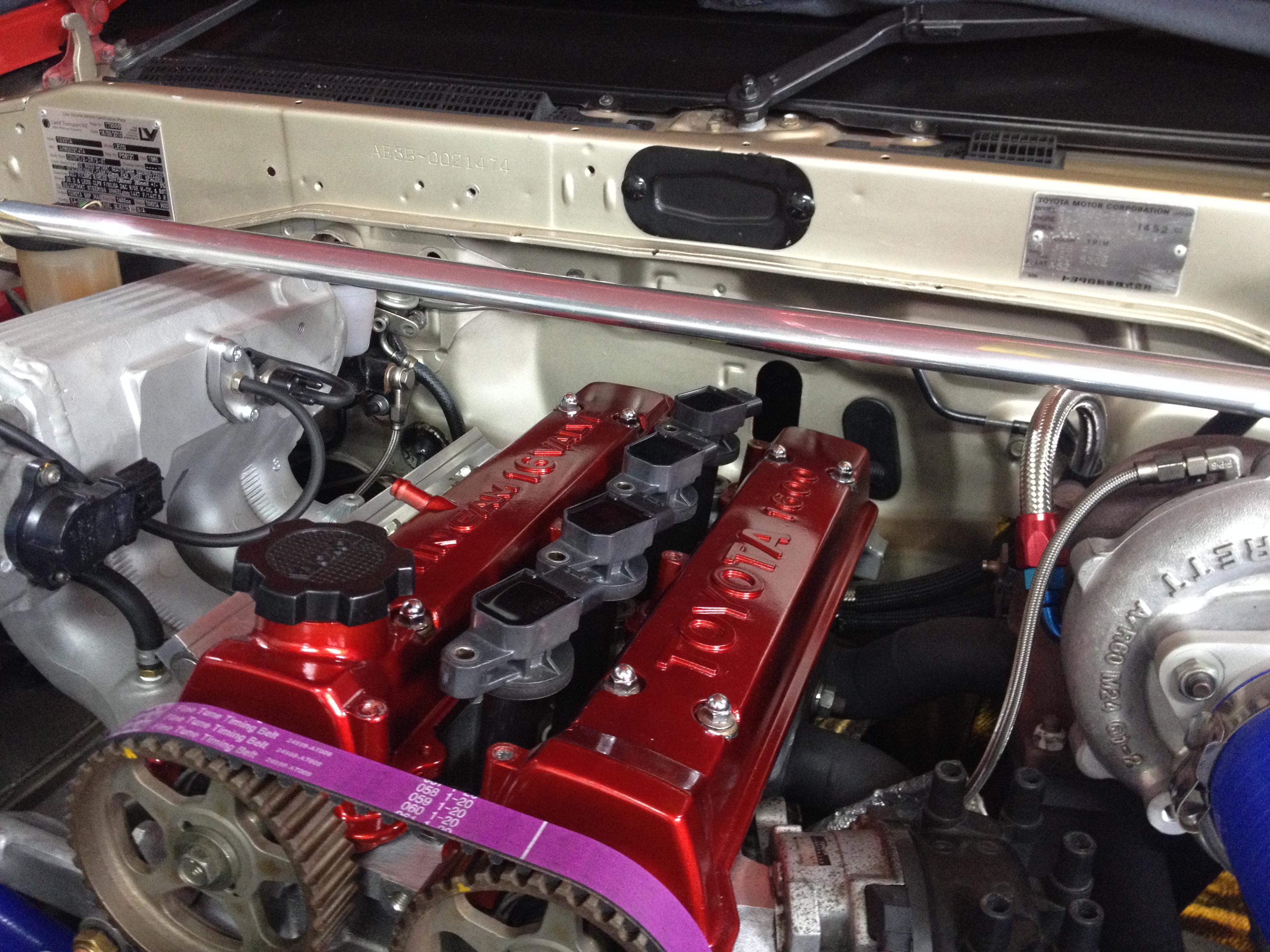
Was messing around with valve cover colours
-
7
-
-
Decided to finish off some loose ends before I pulled the engine, free up some bench space and all that. I had started on a brake upgrade before the last track day but ran out of time to finish it. I had been talking to Barry Manon about his Wilwood setups, but he didnt have anything to fit a 14" wheel, so I grabbed his 15" brake kit to see how it would fit. Ended up having some other adaptors laser cut to bring the caliper in towards the center more. Picked up some BMW Mini 276mm Brembo blank rotors, re-drilled them to suit the hubs, opened up the centre bore to 68mm and added 8 curved slots to each face.
Had to machine a 7mm spacer to sit between the rotor and the hub to get adequate caliper/wheel clearance.
Gave the hubs a bit of a paint and put everything back together.
From the inside, pretty close to the wheel center. If it wasnt for that radius on the inside of wheel, I could have fit a 300mm rotor. Had to take a little off the lower control arm to clear the rotor too.
Also noticed when I took this picture that the bolt heads for the castor arm and knuckle were actually hitting on full lock, could of only been cause the suspension is drooped but never the less, decided to do something about it. Removed the castor arms and countersunk the holes. Hellaflush yo.
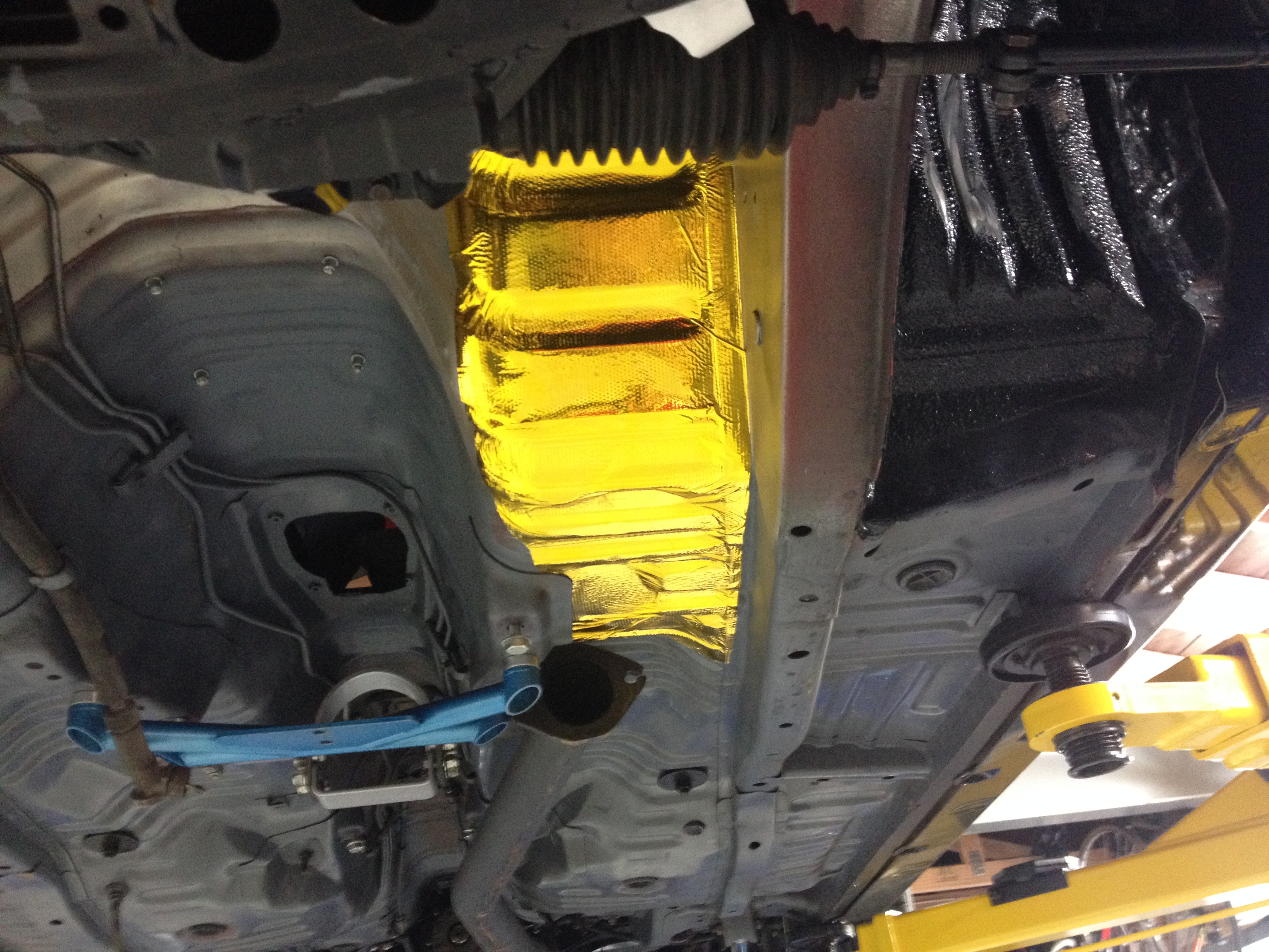
With the brakes all done it was time to look at pulling the less than healthy 4AG from its place. I was off work for 4 weeks stuck in a sling, recovering from some shoulder surgery, so I tried to keep busy by doing little things. Had a heap of this gold reflective vinyl left over so decided to stick it in the engine bay where it gets a fair bit of heat from the turbo and exhaust etc.
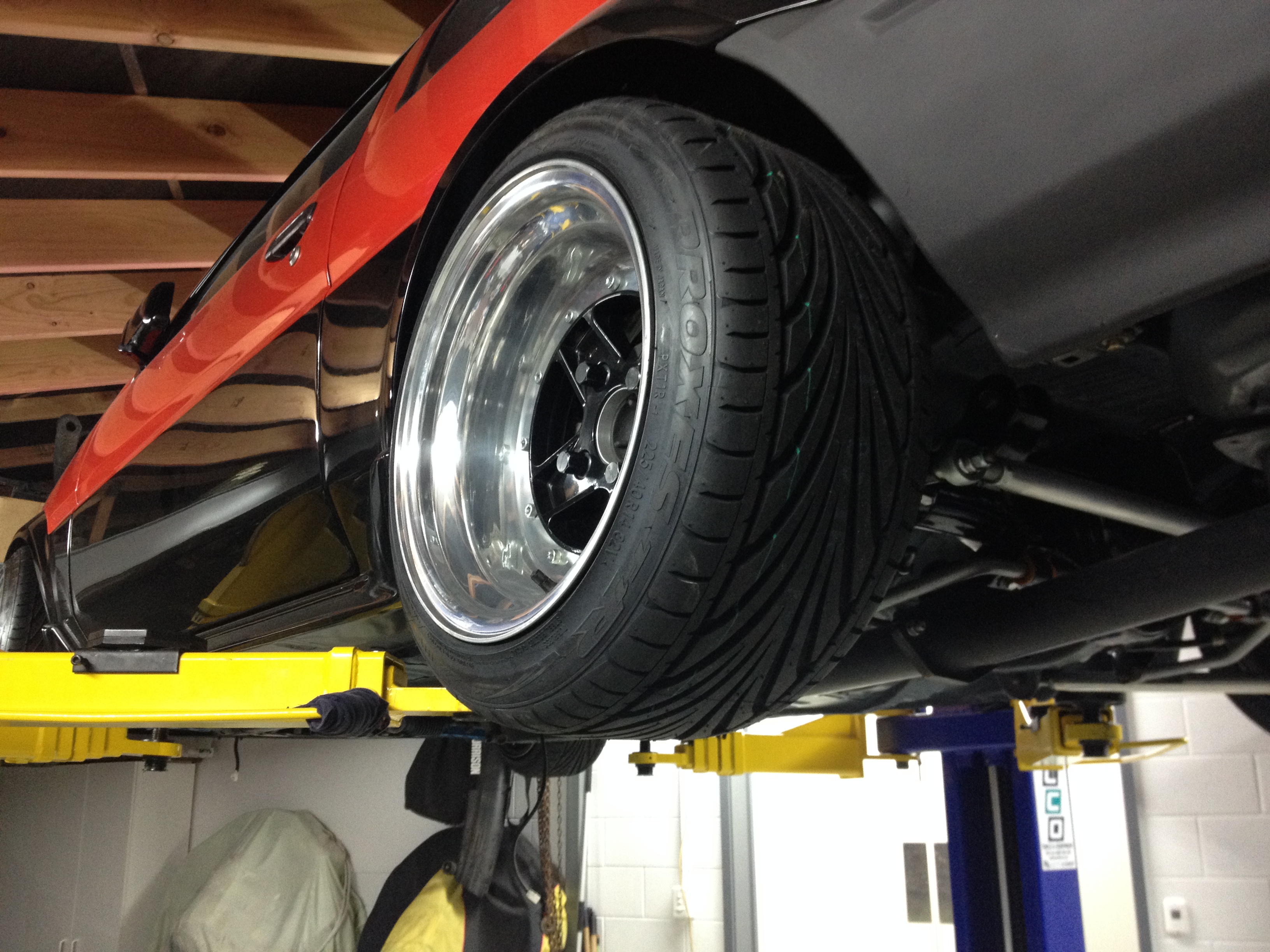
Also had a little front tyre issue at Pukekohe, wheels were getting caught on full lock on the inner tubs making it quite hard to turn off from full lock. So decided to go back to the 195/45 T1R. Id much prefer to use the Bridgestone as I think its a better tyre as far as grip goes, but its just too chubby in 185/55 with no other size options in 14". Anyway, with 195/45 T1R upfront (took them off the rear wheels), there was plenty of clearance everywhere but I needed some new rubber for the rear now. T1R also come in 225/45/14, so I grabbed a pair off those to go on the rear. They sit nicer on the 9j rim.
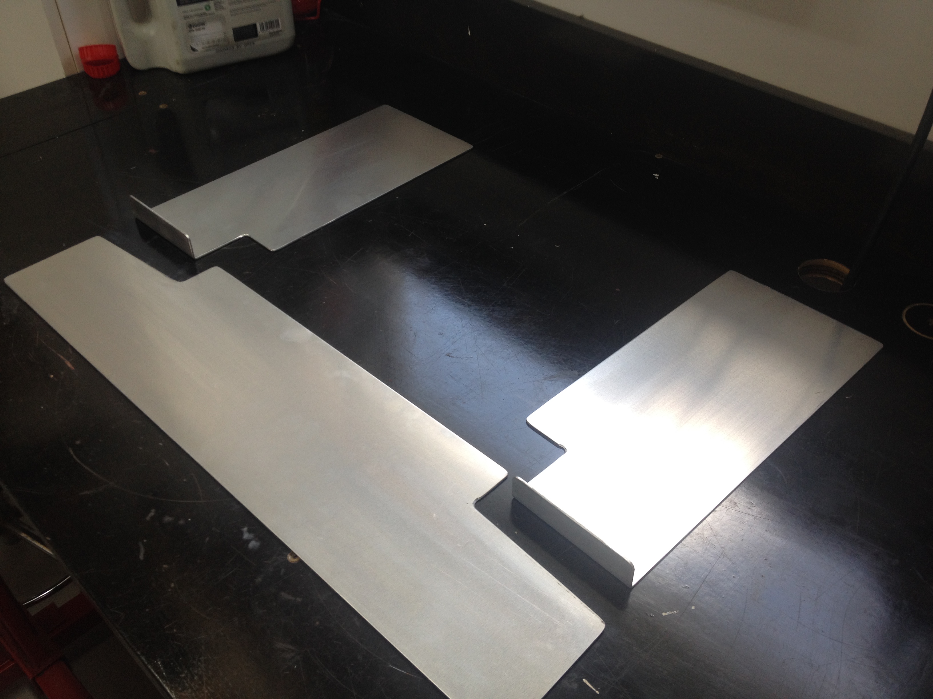
Tuned up some ducting for the radiator and intercooler as well. I made some cardboard templates and had my mate Graeme at SMS fabrication cut them from aluminium for me.
Drilled a few holes, bolted them together
-
3
-
-
I did a track day at Pukekohe with the new power figure, car ran real well all day. Only issue being that the AE86 brakes were a real let down and that there was a high speed vibration. So I pulled the drive shaft out to get it checked/balanced. Turns out it had approx critical speed of only 7000 rpm and in 5th gear at 7500 rpm (engine speed, which I was almost getting to in 5th) the driveshaft will be turning 9500 rpm so I was pushing the limits of it. Decided to make a 2 piece drive shaft instead which puts the critical speed in 12000 rpm + range. Purchased a second hand 2 piece Hilux drive shaft and a hanger bearing/mount to suit the AE chassis.
Here is the center mount with the right hanger mount on it.
Took a few quick measurements and cut up my drive shaft, front half here. Left a little extra on to machine off once I had turned the spigot on the center mount to guarantee I got the right length.
And here it is all bead blasted and tacked up making sure it fits.
The drive shaft went to get balanced, so decided to make a new gearbox cross member (again) to raise the gearbox 25mm, which puts the output shaft back to factory location and reduces the working angle on the front UJ down to around 2 degrees instead of 6 degrees. I thought I had a few more pictures of it as I was making it but this seems to be it
Notched a another bit of pipe and added some flat bar for the gearbox to mount to. Had to make a V shaped mount to bolt to the gearbox, allows me to bolt the gearbox to the cross member and shim it if needed to fine tune the drive shaft angles.
Drive shaft back, painted and in the car. Ended up making some 10mm spacers for the cross member, just helped to reduce all the working angles on the UJ's down to 3-3.5 degrees.
Brother and I went to another track day at Pukekohe, the drive shaft worked well for me which was good. Brothers car ran faultless all day. Kris sent me this vid as he was there in his red KP Starlet
Was a pretty good day, but by the end of the last session the engine wasn't sounding that flash. It had developed a light knock in the bottom end unfortunately. I wasnt expecting it to even last that long to be honest. So the engine build begins...
-
8
-
-
Oh right. It all looks pretty good though, will be interesting to see how it goes once its all sorted.
-
Is it just me or is the I/C and rad on the piss?
-
What are your plans for the rear tray? Looks the bidness.
-
So, I had been thinking about making a new exhaust manifold, proper merge collector, equal length etc. I had never made one before so thought it would be a good challenge. Did a bit of research and got some advice from some people (thanks Kris!) and thought Id start with making a merge collector. I made a jig so I could cut the angles I needed in my saw at home, I went with a 15deg cut just to see how it would come together and I am a little limited for room.
Skip a few steps
Finished welding the collector, shortened it up too
Machined an exhaust flange
Picked up some bends. These are 1 1/4" SCH40 short radius bends. Got the first 2 runners tacked up and equal length
Finished welding up all the runners. The last two I thought were going to be the easiest, but trying to get them equal length and still clear everything was a little tricky. Managed to get them pretty much all equal length (within 5mm from the longest to shortest), thats why the runners look a little funky.
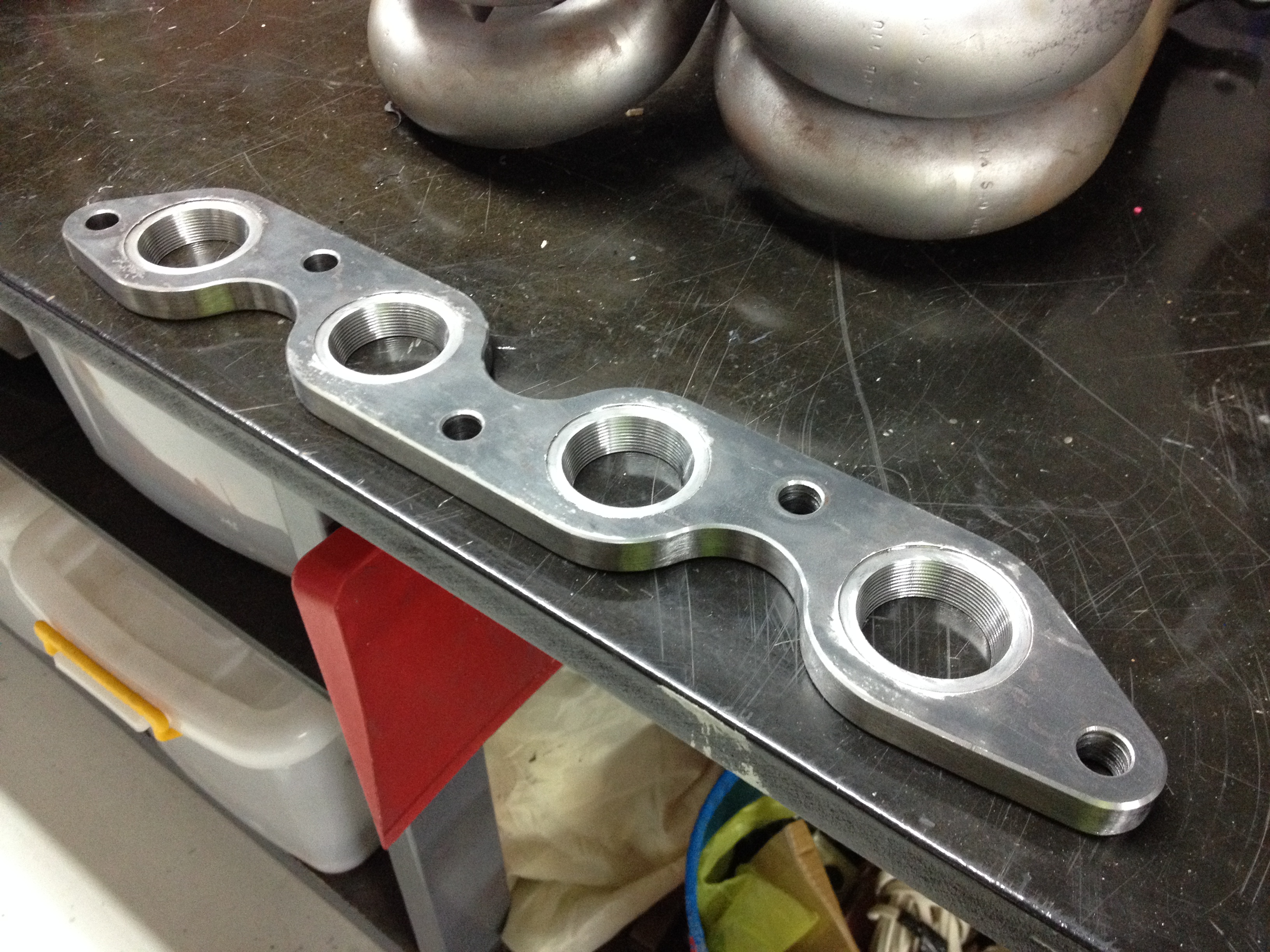
Decided to machine a new flange. The DXF file I got off a forum for the other one wasnt overly good interms of fitment and decided I wanted the ports to taper from 30mm to 35mm to match the pipe and exhaust ports.
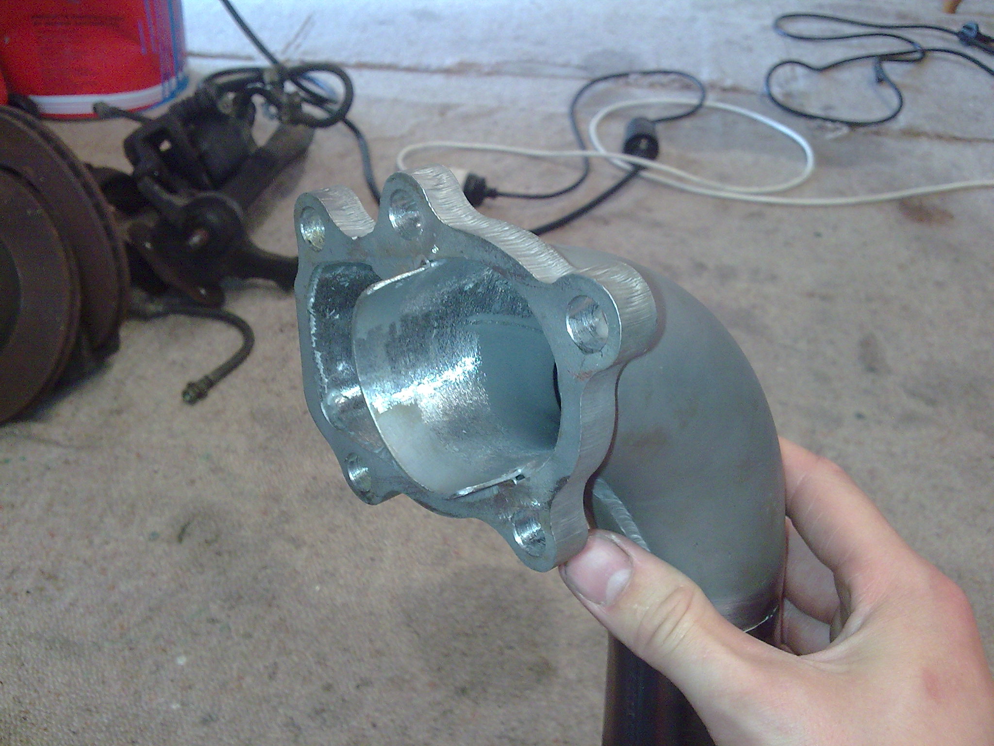
New down pipe, a lot simpler in design now that I am using an external waste gate and probably a lot better flowing than my original one. Instead of welding it to the rest of the existing down pipe, I did a slip joint that this slips into which makes it alot easier getting the turbo on and off not having to go under the car and bolt the whole lot.
After adding a waste gate port for the Tial gate and some heat proof paint and bolted it up
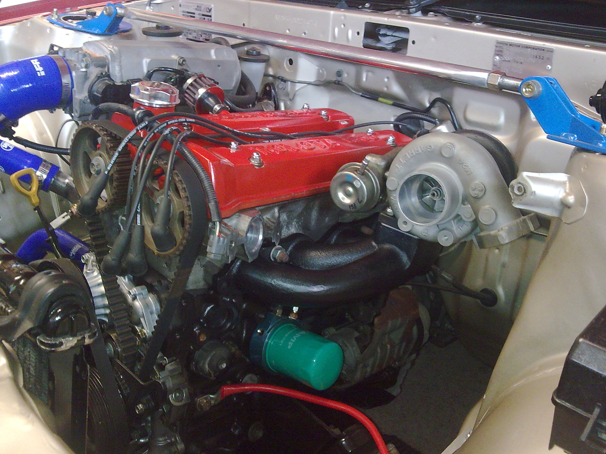
The T25 turbo had some weird issue where it constantly sept oil pass the oil seal, after adding an oil restrictor, bigger oil drain and even replacing the seal (turbo was rebuilt already) it kept leaking. Decided to upgrade to a T28 Garrett turbo from a Nissan S15. Got it tuned with the new manifold setup and T28 turbo. Ended up going with 470cc Siemens Deka Injectors and upgraded the fuel pump to a DW300 unit. I was pretty suprised with the results to say the least! Found some complete pics of the manifold too. Anyway, less talk moar pictures.
I wasnt expecting to make 180kw at the wheels, I was hoping for atleast 150kw. It went bloody good though!
-
9
-
-
Yup same car, Peter from NZPC (at the time) had his datsun at Grants shop at the same time I had mine there, so he was keen to feature when he saw it all "finished". Made heaps of changes since that photoshoot, so I'll continue updating and get it to present day.
-
This is awesome. I love it!
-
So the next logical thing I should of done was get it tuned, but I put that on hold for a while. During the change to the turbo setup I picked up a fibreglass bonnet and a pair of side skirts from Mike Shaw Fibreglass, figured I would address the exterior. Like his other products I have (the duck bill and front lip), fitment was good! The bonnet was pretty much just so I can shave a few kilos off the car, only weighing 6kgs and factory steel bonnet is 14kgs. Bought a pair of carbon fibre flush mount bonnet pins as the bonnet doesnt use the factory latch.
And after breaking my right corner light nearly a year ago now I think, I finally got another! Had a bit of over spray on it, and the lenses were a little dirty on the inside but it cleaned up okay. Front end looks a little more complete now
Also picked up a pair of front guards, which werent mint condition with some small amounts of rust in various places, but they were perfect for what I wanted to do with them...
I cut off the flare section on the front gaurds and use it on the rear of my car to fix the damage. Pictures speak a thousand words, so here is a post from Kris's blog where he has already performed this: Guard work | Garage 4AG. Like I said, my next step was supposed to be dyno time but I changed my plans and decided to see Grant at GT Refinishers. Initially it was just to sort out the rear guards and leave them in primer, but after thinking about it for a week I decided Id get the whole car paneled and repainted. It had been at Grants for a few weeks and was coming along nicely. Managed to get a few photos of it mid paint. Here it is with some black on it, waiting to be masked up and the red sprayed on.
Then a few weeks later after picking it up, got all the final pieces back on
Got it tuned after that at last. Was hoping for 120kw, but 114 was still a huge improvement and was stoked!
Although the T25 didnt stay on there for long, had some issues with it... More next time.
-
8
-
-
Yeah, would of liked to been able to bang 4th on the apex of the sweeper, Ill locktite these wastegate banjos in from now on and have crack at it on high boost. Ill try some faster and more interesting entrys next time too!
-
Did you have it at taupo this weekend? how'd it go?
I need to get to one of those days.
Yeah I made the trip down, was a good day! I wasn't driving properly for the two sessions in the morning, then decided to man up and drove like I should and it was all good! Had the banjo bolt for the wastegate fall out so didnt have any high boost, 160kw wasnt quite enough to grab fourth on the exit.
Heres a quick clip
Jealous of fab skills.
How much power you make with the turbo?
Cheers mate. Back then with T25 it made a 115kw, probably one of those low reading dyno's... It gained 35kw, but it felt like alot more than that haha.
-
3
-
-
- Popular Post
- Popular Post
In the quest for a little more power I got my hands on a rebuilt T25 turbo. I didnt want crazy amounts of horse power, so this size turbo is just about right
Picked up one of these cheap bolt on cast manifolds
Exhaust fab began
Wasn't a lot of space to work with
Welded in a small divider to separate the turbo and waste gate to reduce turbulence
Some heat proof paint and some heat wrap applied
Then started to mock up the intercooler
Carrying on with the rest of the turbo setup. I machined some new lower rad mounts, to space the radiator back to give me a little more room for the intercooler.
Bought 2 slim 10" fans to replace the 12" one I had, made a little bracket to hold them
Little bit more done with the interfooler setup and radiator mounts. I was going to try and fold something up for the upper rad mounts but decided to machine them instead. Started off with a solid bit of 32x32mm aluminum like so
After about 1 1/2 hours of drawing up, tool pathing and machining in the CNC mill, the solid blocks looked like this
Machined off the rest of the stock material off, gave them a quick polish and glued some rubber to the inside of them
Still need to drill some holes in them to mount them properly. Intercooler sort of in with some temp brackets
Fast forward and
-
14
-
So carrying on, I got a chance to really test the new rear end setup (as well as the whole car) down in Taupo. Got an alignment on the Friday arvo to set the rear end up. I was expecting the housing to pull and bow from the welding and throw the alignment out, but came out okay at 0.5 degree negative camber in the rear and 1mm toe out each side. After that the car was already for the weekend. Headed down to Taupo early Sunday morning for another drift day held by Chris/Zero Class. Was a really good day, car went really well too so I was stoked about that.
Have a few pictures here:
Had a few tires delaminate and do some damage, first one tore the side skirt off and I must of ran it over, and did some damage to the already fucked guard. Second tire made it worse haha. I wasnt too fussed, needed fixed anyway.
Some moving pictures from that weekend
-
2
-
-
Decided to do a track day at Pukekohe. Was heaps of fun, car went really well with the 4.9 diff ratio, although I was at 7300-7400 RPM in 5th gear at the end of the front straight (rev limit is 7500). Was the first time I got to test out the gear stick properly and it was perfect! Suprised at how much grip it still had for street tyres too. I put a muffler on the rear for the day as I know how hard they enforce the sound limit at Puke, but still got a warning at 97dB haha. Ended up leaving the muffler on, sounded much nicer anyway.
Got my mate Goob at Herbert Fab to weld up this over flow for me before the track day. Gives me a little more room for the intercooler piping in the future.
Decided I was going to look over the rear end of the car again, make some improvements where I could. So I made up some new rear diff control arms using 6061-T6 grade aluminium round bar, and QA1 chromoly rod ends and machined up the spacers as well. Panhard rod not pictured here, but I used the 3/4" ($$$) rod end instead of 5/8 for the panhard. Here's some pics
And the spacers to compensate for the difference in width between the factory control arm bush and rod end, and a neat fit for the bolt so they dont slop around.
I went to fit these arms up, and I had to make them all different lengths to get them to fit due to the fact that somebody had made a mess of the diff swap. Decided I would cut all the brackets off my diff and re weld them back on in the factory location, how they should of been done to start with. So first step was to get a factory diff and make up a jig to get all the mounting points off. Luckily I was able to get my hands on a factory AE86 diff that hadn't been modified or bent. After measuring up the factory 86 diff, I could really see how far out the mounts were on my Hilux diff... Top control arm mounts were 25mm further apart than they should be, lower arm mounts should of been 40mm further apart... I had to make a jig that would locate from the centre of the hub so the wheel base would be as per factory, allow for the difference in overall length from hub to hub as the Hilux rear end was just a little over 20mm wider overall and have the right orientation of the housing to get the pinion angle correct.
86 Diff and jig pretty much finished here. Parallels between the RHS and the machined face for the diff head gets the orientation right.
The threaded rod with the point machined on the end allows for the difference in overall length, center the diff in the jig and locates nicely into the factory center drilled hole in the end of the hub.
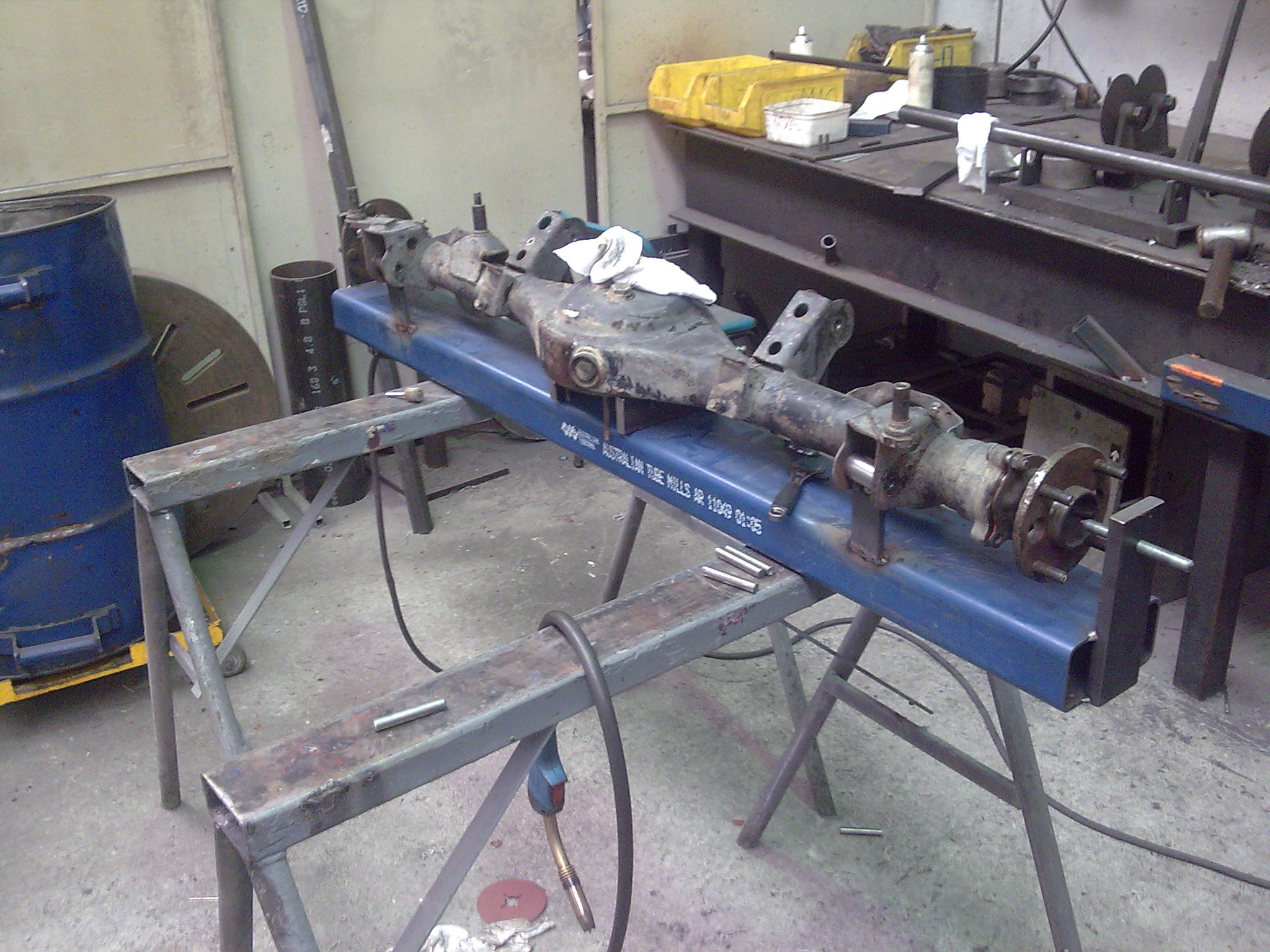
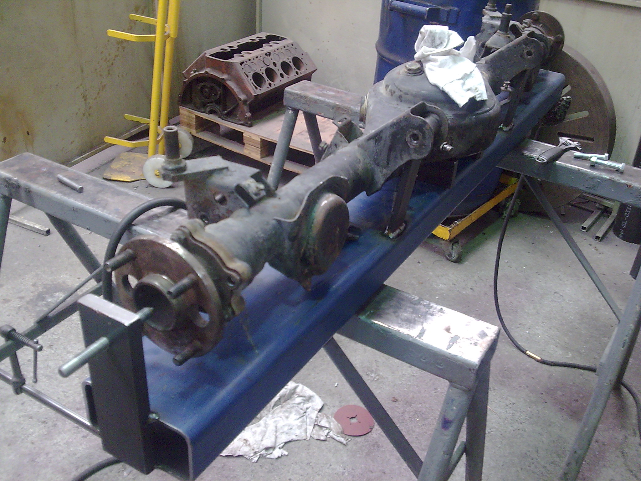
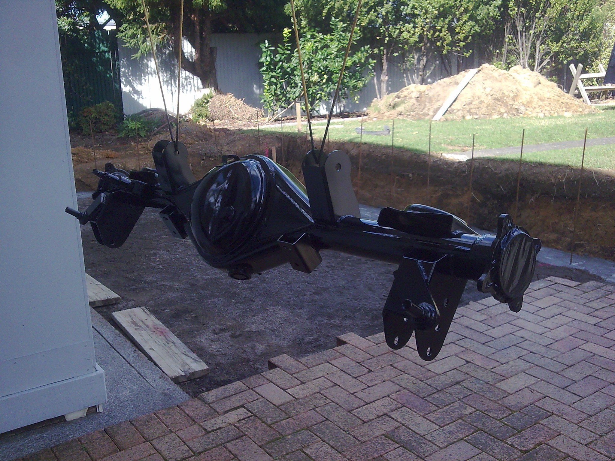
Here is the Hilux rear end after cutting all the mounts off and paint stripping it.
Started to make up some new bits and pieces, new pan hard mount and pin waiting to be welded together
Sort of how it will look once together. Different length spacers to get a bit more clearance around the diff housing.
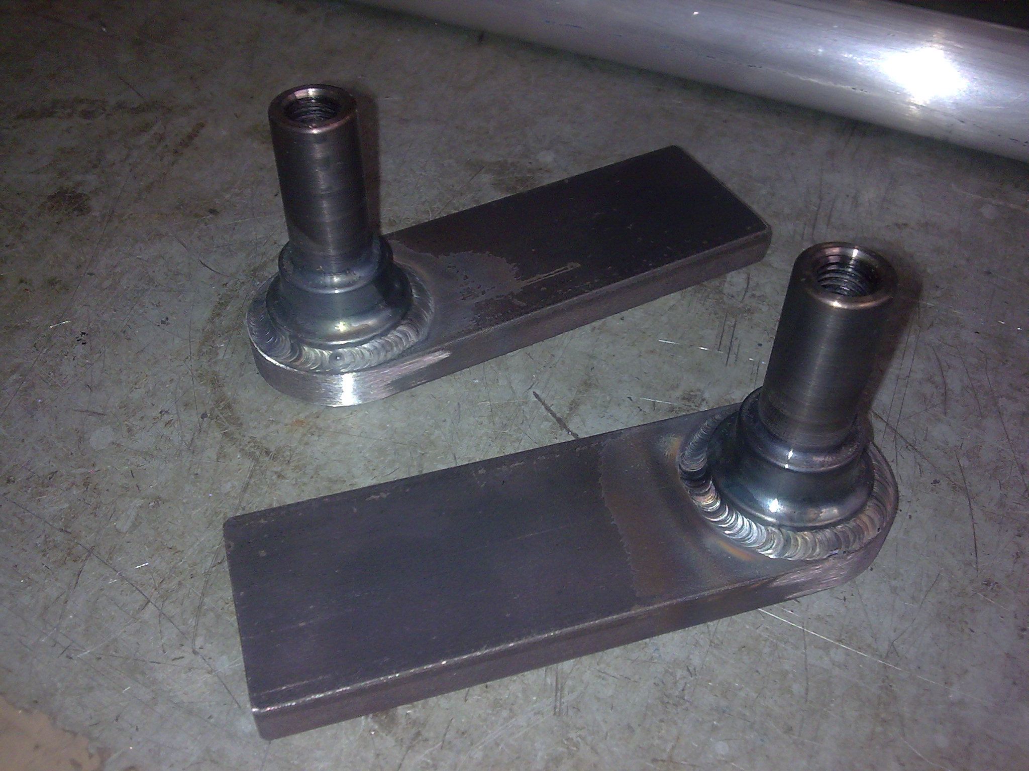
New shock mounts machined and fab'd. These should be a fair bit stronger than factory, so if I want to go to a coilover setup in the rear I wont need to make any further changes to prevent the shock mount from bending or snapping off.
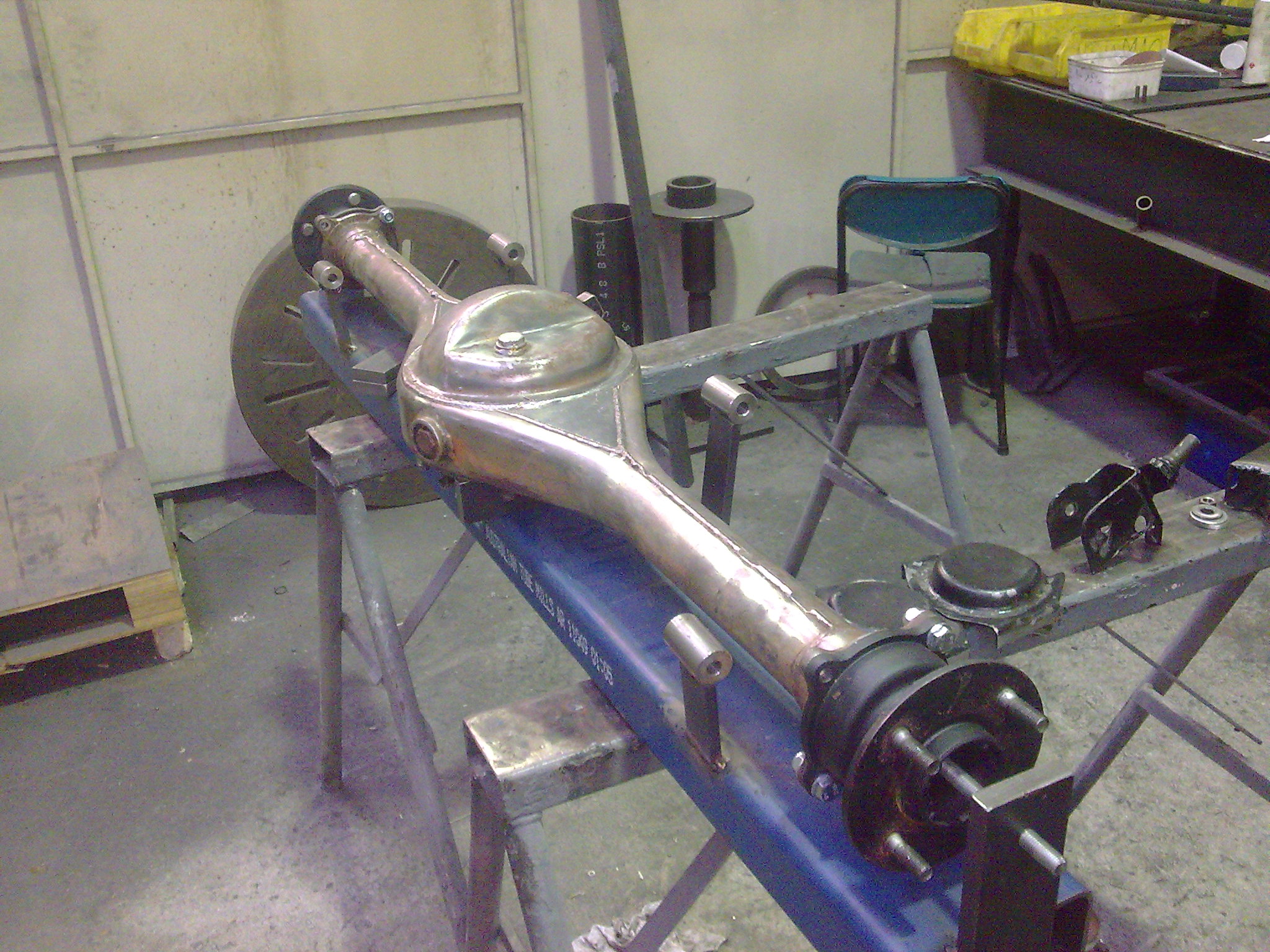
Heres all the new brackets and mounts I had made tacked up on the diff housing.
Got some more filler wire and finished welding up all the new mounts. Cleaned out all the grinding dust, masked it up and put some paint on it
The Hilux diff is quite a bit bigger that the 86 gear, so with the ride height Im running I was having a small issue with clearance. The diff head was hitting where the factory 86 diff bump stop would be just at the end of the drive shaft tunnel.
Forgot to take some pictures before hand, but you can see the shiny mark on the diff head
Which was hitting this piece here I cut out to make room.
Got about another 20-25mm of room to play with now, might be able to get a little more tweaking the adjustable arms also. I was lucky for it to be double skinned where it needed to be cut so I didnt have to weld in anything to cover up holes etc. I put some sealant on to stop water from pooling between the two skins. No picture of the painted outcome though
-
9
-
-
That 4 link setup looks pretty good! What you going to do about the crossmember thats in the way?


PedRac3rs 1985 AE85 Levin
in Projects and Build Ups
Posted
Not sure if I posted these wheels up before, but here they are. They're a Dunlop TE, 14x6.5j. Got them quite cheap off Trademe. They have an unsually big center in them for a 14" wheel, almost a like a 15" center with 14" shells, which I quite like because my SSR MK2's have a small center and you cant see any of the brakes behind them. Anyway, decided to widen these too. Here they are with the raw 3.5" shell from Gavin Bateman after drilling a new PCD through the lot.
Had the lips and spokes polished, centers painted.
Would love to have a full set of these!