


Hyperblade
-
Posts
347 -
Joined
-
Last visited
Posts posted by Hyperblade
-
-
- Popular Post
So onto the next problem, I've had warped rotors for a while (low down on priority list), so i had them skimmed ended up with 0.12mm taken off of one side...
So went out again, car was braking amazingly, I could brake so later and with huge confidence, then they started warping again.
Ok need to sort that out as the rotors aren't cheap. They have also been hitting 600c+ which is not good for rotor or pad life.
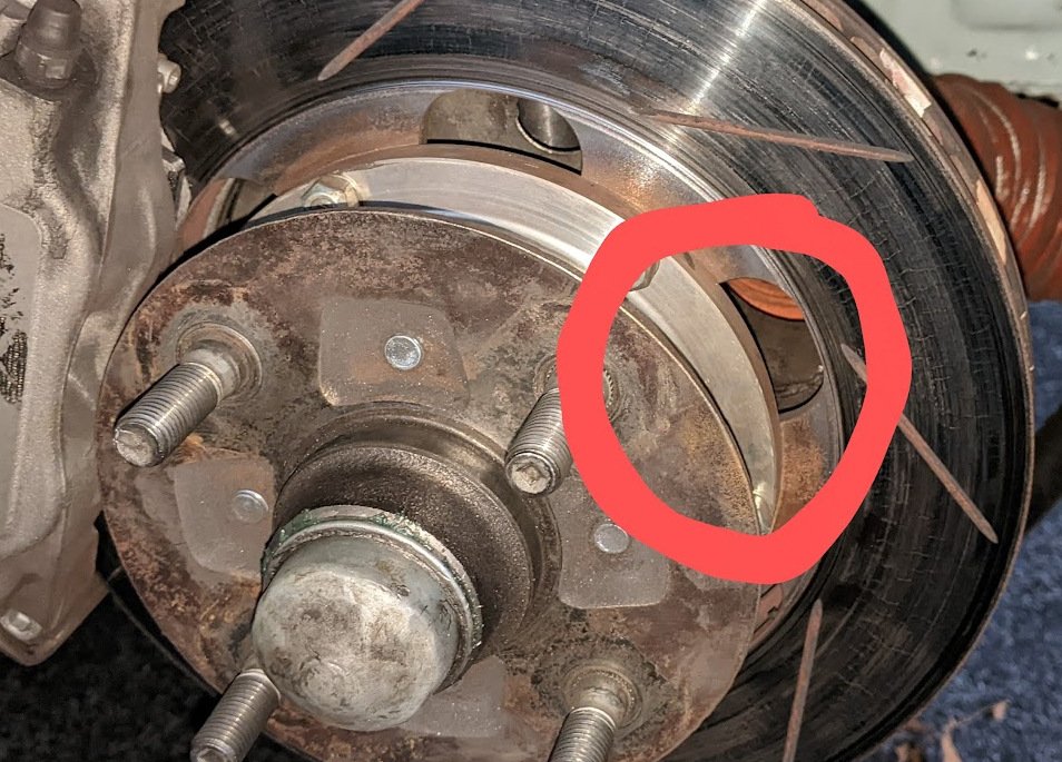
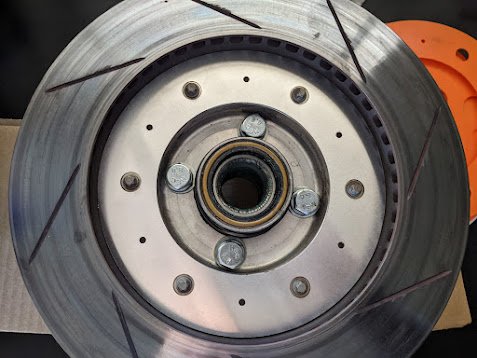
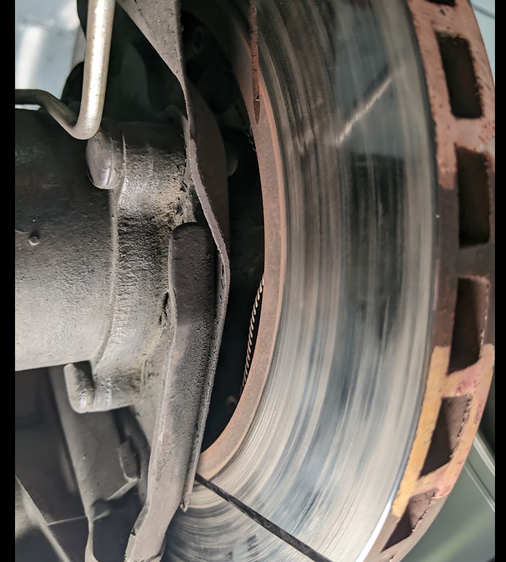
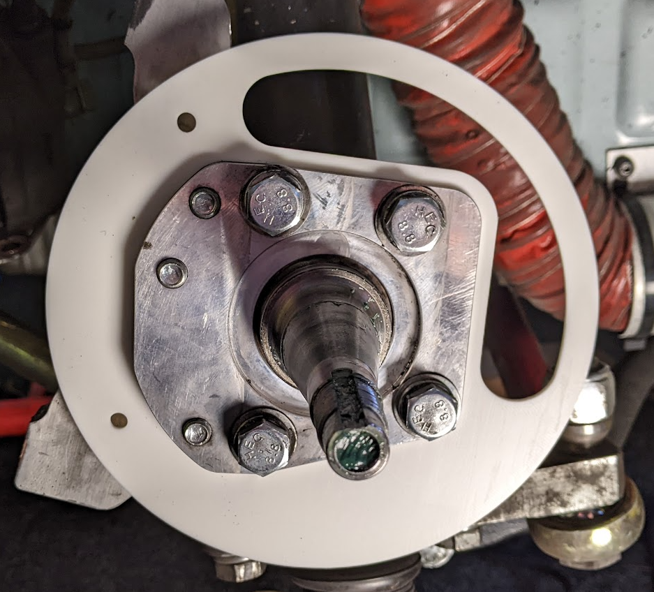
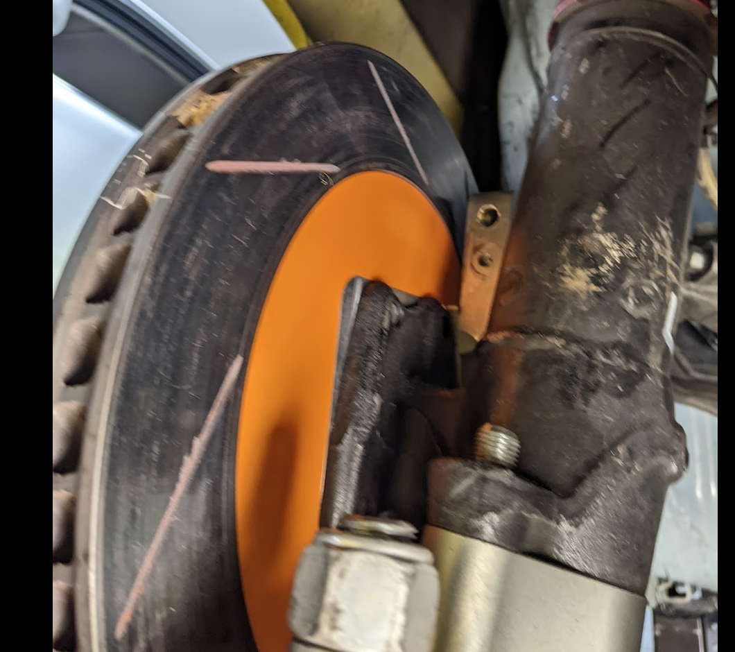
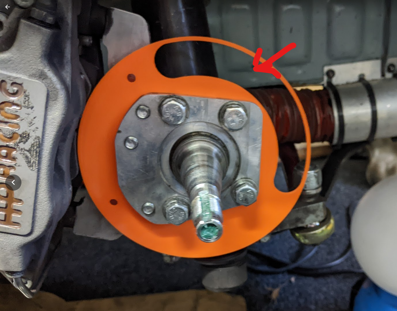
I brought knockoff makita blower and I put it on the intake to the brake duct and measured where the air was coming out.30kph straight in and 10kph straight out the rotor at the red circle, 0 out the vanes.

Granted in hindsight, its bloody obvious, but just hadn't really through through the ramifications and how bad it was.
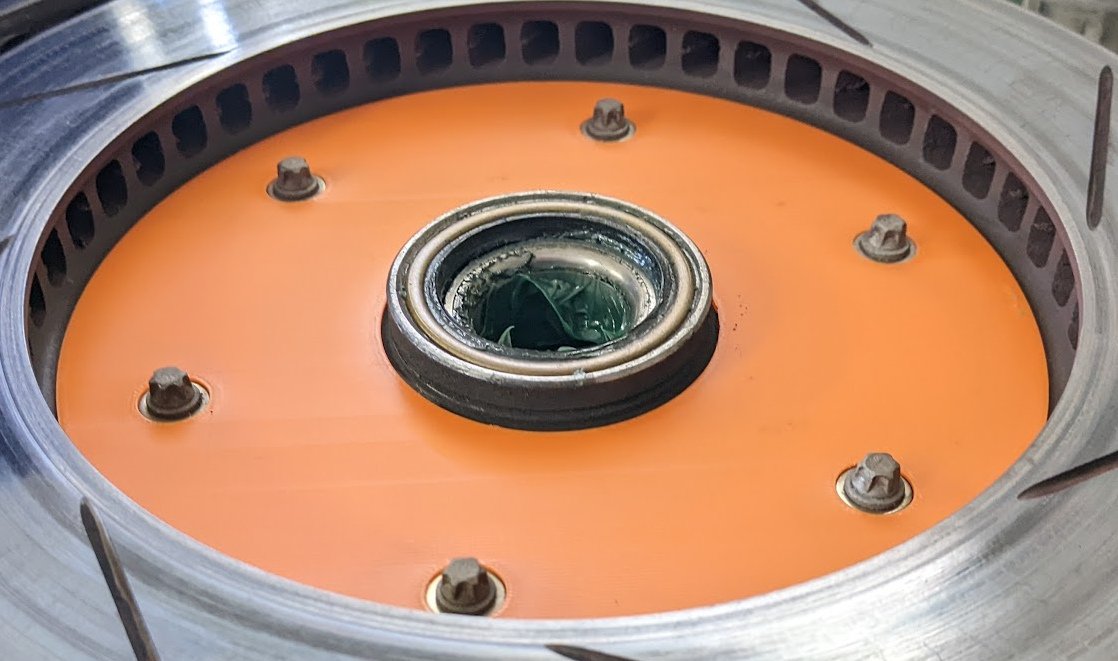
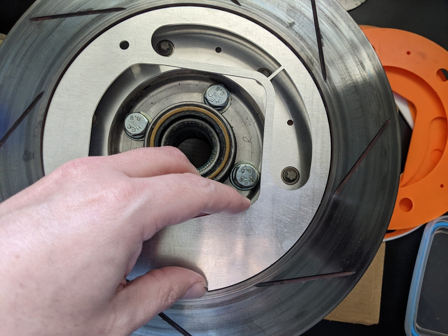
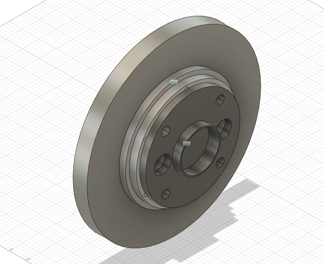
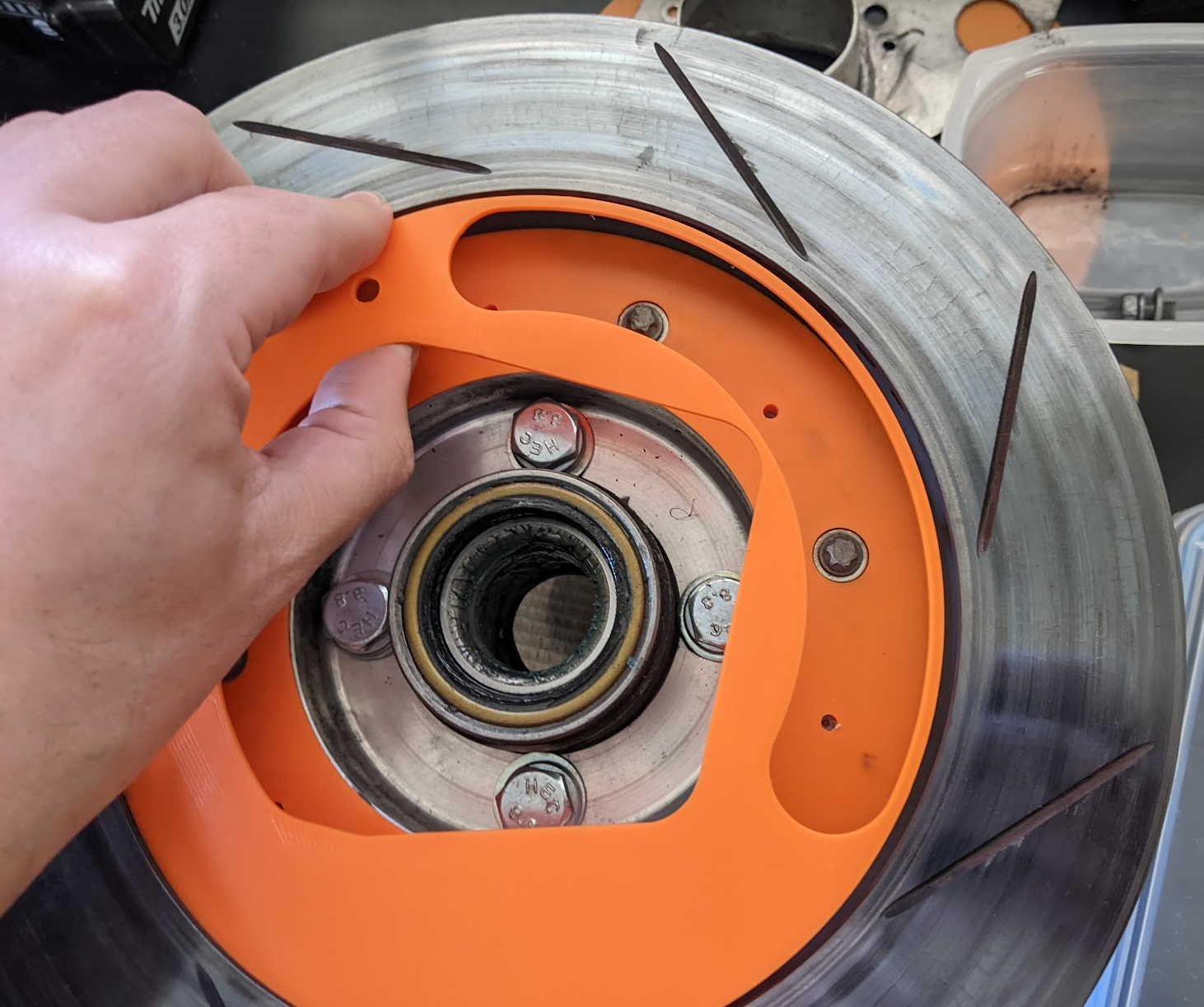
Fundamentally the hat (GP4 Fabrications Kit) is just not designed correctly it should have no holes in it.One 3d print later I had
Testing that alone made a massive different to the airflow (naturally, it's so fucking obvious now) with air coming out 1/4 of the vanes.
Here's the old cooling, so while I'm there i may as well do the job properly and make sure the air doesn't come out the other side either as that could cause warping as well.
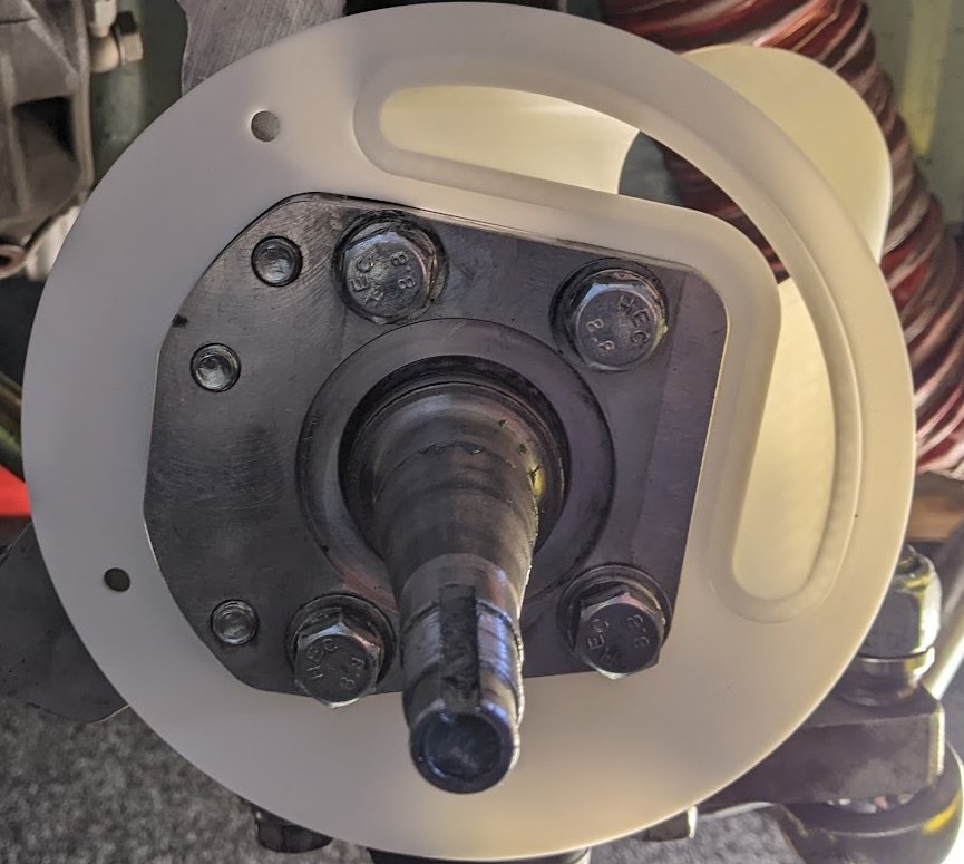
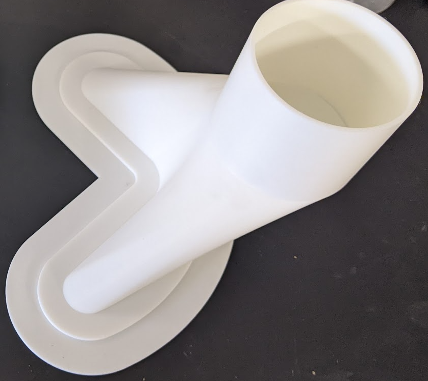
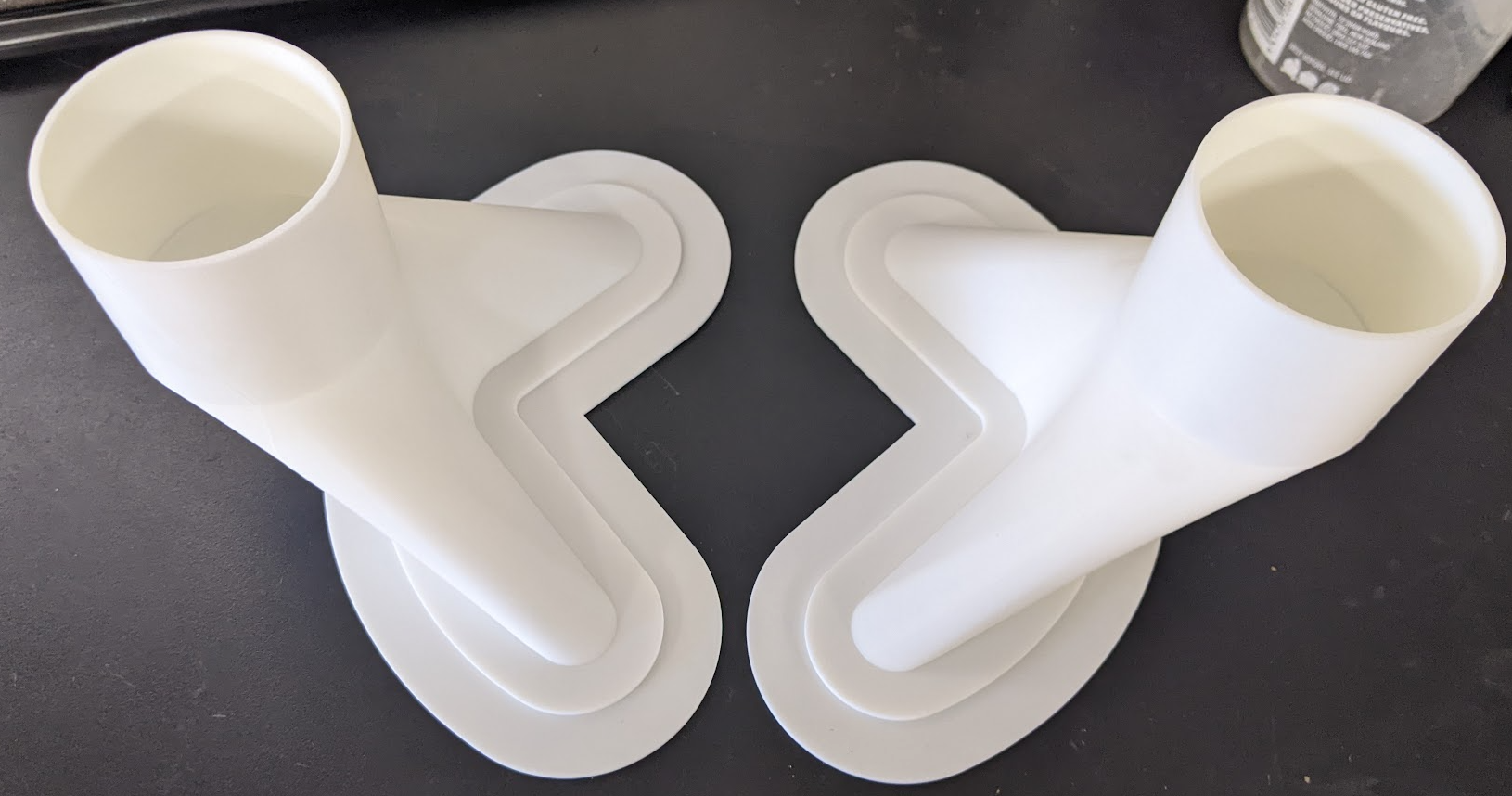
Multiple iterations later we have this
So after getting laser cut we end up with these
Clearance to disk will be adjusted if it requires it.
That's the simple part done, hard part is now ducting the air into it nicely/safely.
You can see the technical chat on that here:
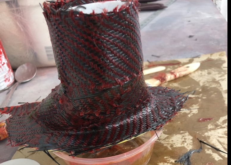
Fundamentally current plan is to go with a PLA mould and fibreglass/carbon/Kevlar on top of it, then softening/melting it out, I have someone doing the work for me whos an expert in fibreglassing.
Heres attempt number one (carbon/kevlar).
He had a go at getting the Mould out but it put up a fight. So I've printed some thinner moulds to see if that makes it easier for him.
However I think if I put it in the oven at 70c it should melt out, so going to try that too, if it works it's very cheap and easy to make the moulds for complex shapes.
Now naturally while the front brakes were working amazingly (being straight and all) the rears are now starting to get up past 600c as there is not a lot of room to get air into them, 258mmx21mm disk with AP Calipers.
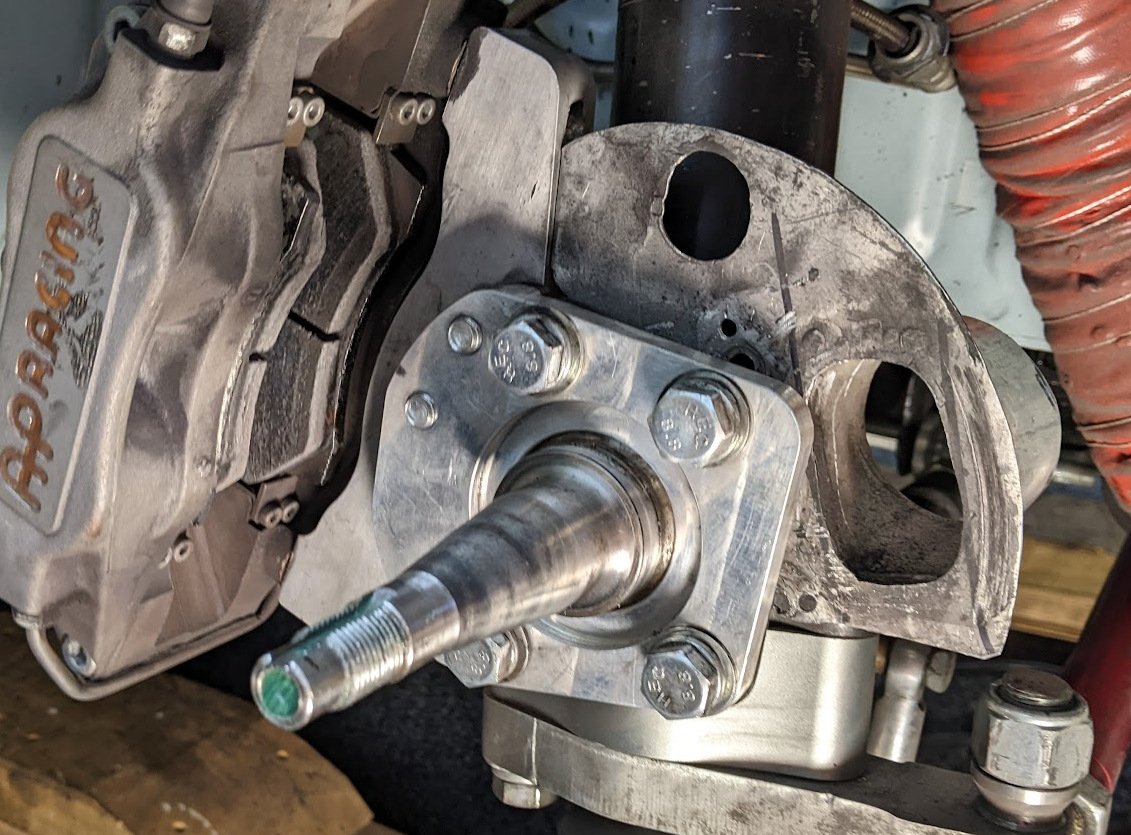
So work is proceeding to see what can be achieved with redoing the caliper mount and/or moving disk outboard for easier maintenance/replacement.
-
 19
19
-
- Popular Post
Haven't posted much as been working through annoying gearbox issues.
So in one of the races I was going into the hairpin and instead of selecting 3rd it went into 1st.
In a honda that would have been engine gone, but as it's RWD it immediately locked up the rears and i had a bit of a moment, but no damage.Additionally in the last race on the last lap as i crossed the finish line I attempted to go from 5th into reverse...
Not ideal...
S2000's run a reverse lockout where you have to push the gearlever down, for some reason it was already down when i went to go from 5th to 6th and so it smoothly tried to shift into reverse (to right of 6th).
The issues:
- The gearstick had always been slow to recenter if you let go, so while braking your trying to pick the center gate, rather then just letting it go then moving it straight forward.
- I probably forgot to lube the ball and the shift lever worked it's way down at some point over the laps so the lockout wasn't in effect.
Solutions
- Pull apart gearbox and double check its ok and put a put a stronger centering spring in and a install an upgraded detent kit (near disaster).
- Lube the gearlever, and get an 80% stronger reverse lockout spring made (works well)
Go back out, and just as i'm starting to do a fast lab in quali shift from 5th into
6th4th...Well that's an even bigger issue, it literally just smoothly went into 4th no complaints and felt like it was going into 6th.
Thankfully I had dropped the shift point from 8800 to 8000 to see if it would improve the overall laptime, so the engine only hit 9550rpm...
So some head scratching later, and pulled some of the upgraded detent springs out, which improved it from going into 6th 10% of the time to 95% of the time just sitting in the garage.
Went out again.
Unbelievably did it again, but it took until race 3 (good footage of me dodging a stalled car on grid as well).
So at this point this has to be sorted properly, the engine will not take much more of that.
Looked at hand position, concluded I hadn't really changed it between good and bad.
So the Issues
It turns out the detent kit was not installed as per the instructions (plus there was a last minute change to where a couple of springs were put then it wasn't tested), so that's a big issue on my side. However one of the springs puts an insane amount of pressure on the selector shaft (hence why it wasn't put in), to me it's just been poorly designed. So all upgraded detent springs removed, the center spring stays.
But one of the issues is that their is so small amount of movement needed to go from the 3-4 gate to the 5-6 gate.
What do i mean?
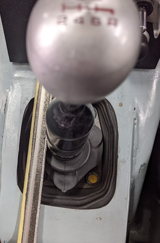
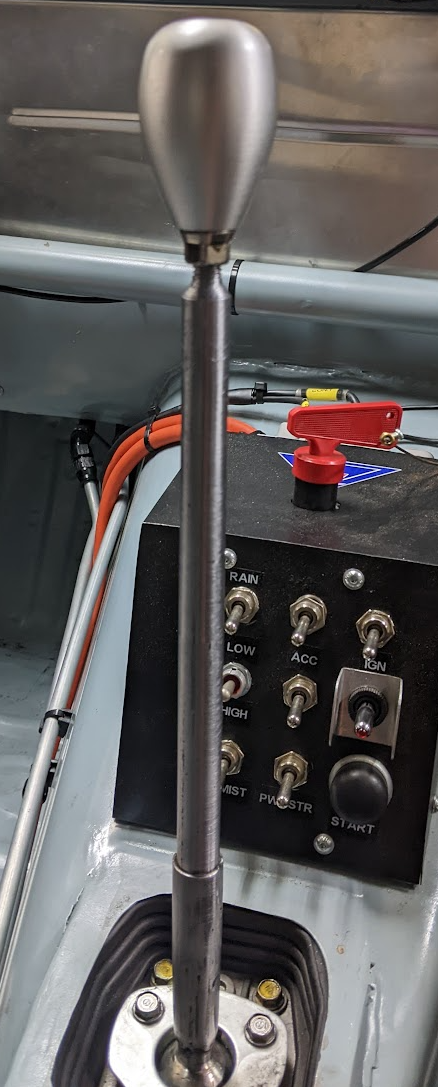
Here's the lever in 3rd,
Here's it in 5th
That and I think the kinematics of my position is not helping the engine/gearbox are on an angle in the car, engine more over to passenger (left) side, so as you pull gear lever back, you have to put more pressure to the right. I think the detent springs accentuated this with the amount of pressure they required to hold it across.
So solutions:
- Make the gear lever longer to give more throw between gates
- Remove the rubber isolator in it to remove any play in it.
- Find out the gear lever is also bent to the right, so straighten it... (this makes the kinematics worse)
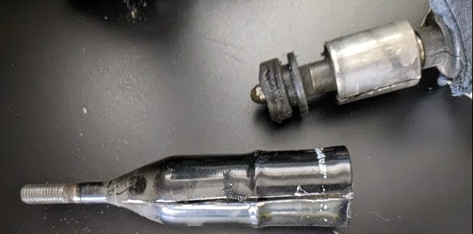
So here's the inside of a Honda S2000 gearshift lever (aluminum sleeve has rubber bonded to it)
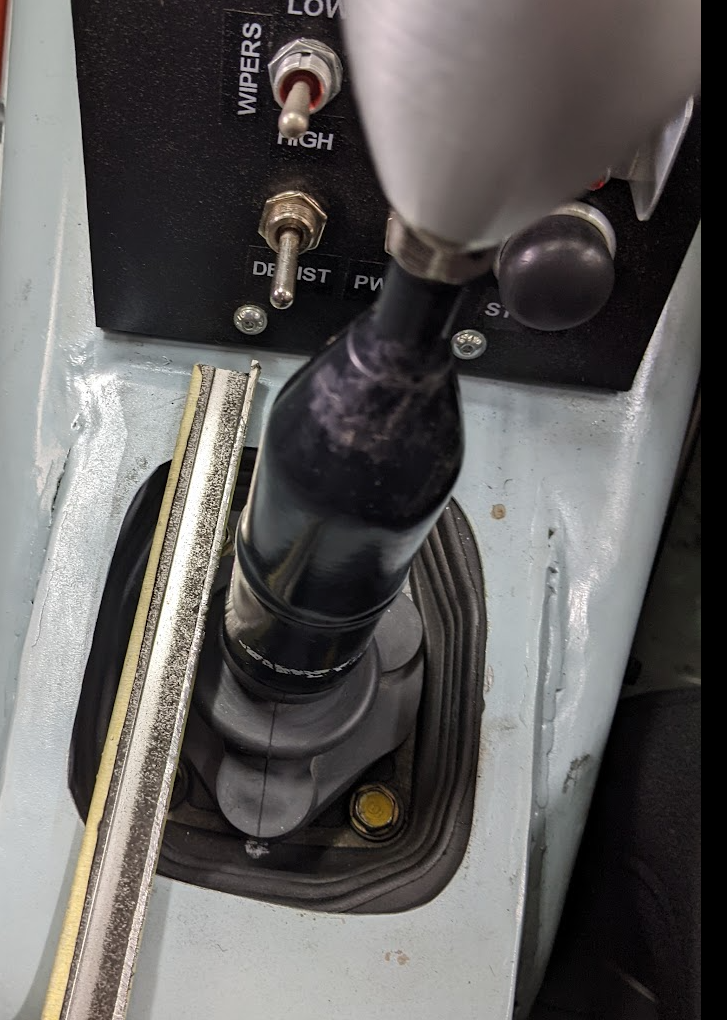
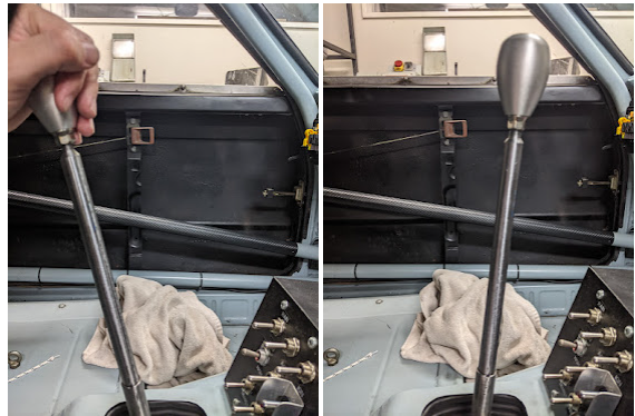
Spend time making up a longer shaft and end up with this
Throw wise it's going to slow me down a bit, which is a good thing.
It puts the lever height wise in the middle of the wheel, which is perfect.
So fingers crossed all those changes finally give me some confidence to be able push it hard again.
-
12
-
58 minutes ago, Bling said:
When do you need it done by?
I have a couple of scanners (Revopoint Mini and POP2), but I don't tend to lend shit out after being burnt too many times. I'm local to you but can't do anything for a couple of weeks I would say as recovering from surgery. Could bring your bits over to scan. Flick me a PM if that works.
Completely understand your position on lending stuff
")
it's a bit much work to take the entire rear axle assembly (AE86) out of the car, but i'll see how I go with manual measurements and hit you up in a few weeks if i get stuck.I definitely have another item you could easily scan (headlight surround) which would make my life a whole lot easier but it's way down on my priorities list at the moment.
I have technical drawings of the calipers etc, it's more just working out where in 3d space they sit compared to housing.
I want to see if it's worth remaking the hat and moving the caliper outboard within the wheel and tolerances are very tight all round.
-
1
-
-
3 hours ago, NickJ said:
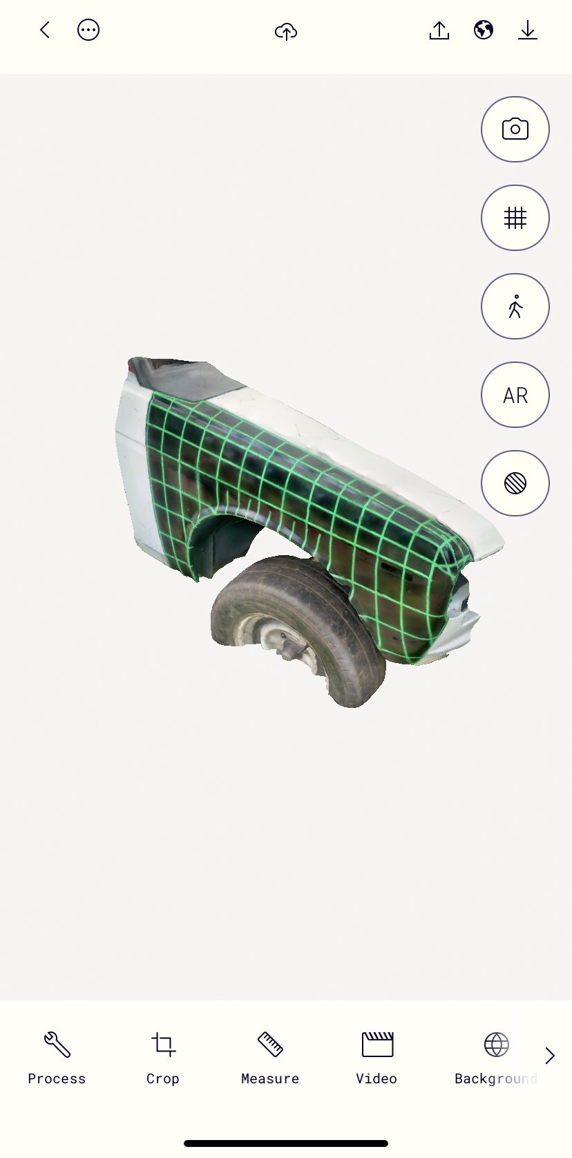
I've been messing around with Polycam on Iphone, $40 for the full app but also has a 7 day free trial, so far the results are pretty good
Lidar on the iPhone definitely helps quality. Unfortunately I'm running android and I was not impressed with the photo scanning.
-
27 minutes ago, Roman said:
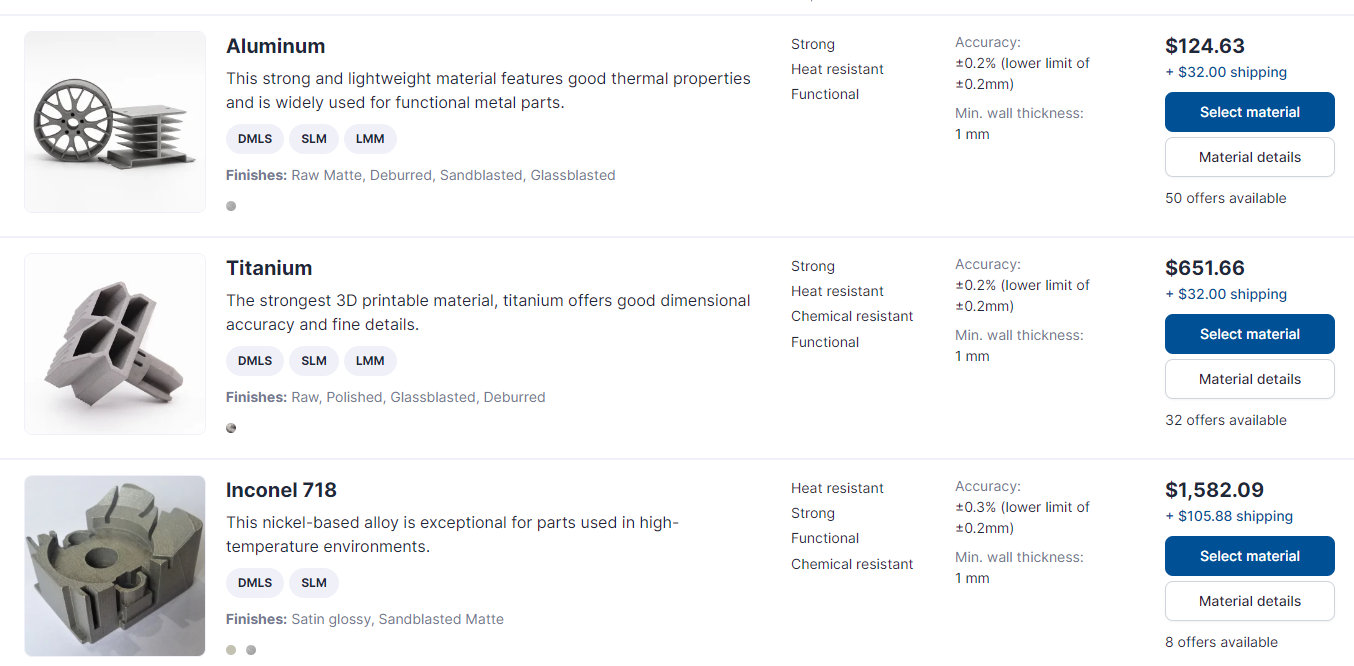
@Hyperblade yeah inconel was more like $1200 each and then well and truly out of my depth to try weld it.
But I doubt i could even make a stainless collector like that for that price.
Especially when you add up all the time spent designing some of this stuff, then tweaking to actually be manufacturable. You end up skipping a lot of steps and saving time. We live in amazing times.
It certainly makes me think twice about 3d printing my intake manifold in nylon, when i can just do it straight to aluminum.
-
3
-
-
Long shot i know, but does anyone in Chch have a decent 3d scanner they would be willing to lend me (I have a decent PC).
I want to scan the inside of a wheel, caliper brackets, rear axles flanges. as I want to remake the caliper mounts, and i'm thinking it would make life easier to see where it is in 3d space.
Happy to pay some money your way for the hassle. -
What a tease, i'm reading "3d printed inconel" and think this is really starting to get interesting, then you understandably cheap out by talking about stainless, lol.
I'm surprised at the prices they are quoting, I thought it was just wishful thinking on my part, but 3d printing metal has to be seriously considered as an option when making a complex part now (assuming they produce a quality piece).
-
1
-
 1
1
-
-
19 hours ago, Truenotch said:
^ This is the method. Fibreglass shoild be ok? But if you do it with carbon it'll be great.
I think the SR86 ones were carved out of foam and just wet laid over top, then dig out the foam afterwards:
Those are interesting in their design, generally my understanding is you don't want to cover the rotor face as it can mean uneven cooling of each side so can promote warping.
Although AP racing say you want 10% of air up each face and 80% through fins, but that's pretty hard for your average punter to design for.
I'm hoping I can skip the foam part and just use pla, that's cheap and easy to produce at home, so if it works is a good solution for other similar parts.
-
So after some reflection on this, I decided to make my life easier by going for 2.5", while I could have fitted 3" in, it just wasn't worth the effort at the moment.
This allowed me to thicken up the outer edge of the plate, and move the air more inwards which is better.
So plate ends up as this.
For the ducts themselves, trying to get aluminium around them was proving too difficult for my skills, there was a couple of compound curves making life really difficult, even when I altered the ducting to be as simple as possible.
I looked at casting but they would have been minimum thickness of 4mm and $1000 odd.
I got a quote for 3d printing them in metal from https://craftcloud3d.com/ (min thickness 1mm)
Actually not to badly priced $262nzd delivered for the 2 of them (in ali).
But the current plan is to take these moulds in PLA and just wrap them in fibreglass, then melt the moulds out (found a friend willing to try it).
-
9
-
-
On 08/04/2024 at 17:23, xsspeed said:
Whats a k24 do in n/a guise compared to the 2ar?
Race motor (cnc head, cams, pistons) on npd100 300hp odd (think that was at wheels too) designed for endurance racing, few $$$ involved but not crazy money.
-
1 hour ago, mjrstar said:
could you maybe make 2 halves from some MDF, then use that to press the shape into aluminium and then weld together, if you get some O state alumimium its very workable...
Good idea, I have seen something similar done with 3d printed molds.
38 minutes ago, Unclejake said:One small thing we used to do when I was racing was to move the car (hand push a few hundrend mm) in the pits a few times after each race.
Our thinking was the hot calliper reduced heat dissipation from the hoy rotor so if we pushed the car further back into the tent every few minutes after the race the rotor would cool more evenly.
I have no idea if that really helped or not though. Ha.
This is actually a thing, pads create a hot spot, or so I've been told. Have been moving it after racing, but believe warping occured during race.
-
17 minutes ago, NickJ said:
Yeah/Nah/Maybe
Not really an easy short answer cos the variables are huge in composite design, more shape complexity just means more nasty tooling design!
With CF, rule of thumb, anything under 2mm precision needs post machining, of course with specific part experience and process/tooling/layup development that can be shrunk but this is a safe start for a one-off.
If I was making this for you, I would be going for a sheetmetal solution first to get further clarity on air flow requirements, its a dicky subject so before investing in tooling and materials, getting a good idea the plan works (just heavier) is a good start, Aluminium also gives great track day modification options when things don't work out as planned! In one day I could CAD and manufacture both left and right from 0.8mm Al sheet. In one day of design for carbon i'd be lucky to be unloading the first tool from the mill.
As for manufacture, not currently sure who would take this on sorry, most of the suppliers I have worked with would want to be making 100s. Technically I have all the gear here to do it, (mould making, vacuum pumps, ovens etc) but the cost might be prohibitive?
Are you still WFH? i've got plenty of free time, happy to discuss in depth over a coffee/beer
Yeah was figuring all of that would be the case and was wishfully thinking it might have got easier, nothing is ever cheap being 1 off.
Sounds like I'm going the aluminium route, i've take the time pressure off myself as i want this done right, so I can spend some time mucking around and see how far i get.
Yep still WFH most days, thanks for the offer, but i'm probably ok to proceed at this point (but if you ever want to pop round and check it out just sing out), if not will give you a yell
Thanks everyone for the thoughts/advice appreciate it!
-
3
-
-
6 minutes ago, ajg193 said:
Is there a particular reason to stick with 13" wheels? (Cheap supply of tyres?)
Going up a size or two would remove a lot of bottlenecks
I run the ex TRS Michelin slicks which are 13" and have amazing performance and cost me bugger all (new are $450 a tyre).
I have a fairly large stock pile of them and the car looks and handles better on them.
Yes, my life would be a whole lot easier if i ran 15" but it's worth the pain for the performance.
-
1 hour ago, NickJ said:
I've designed and had made exactly this from carbon, it can be done and CF is no dearer than the other options, its the tooling, time and consumables that add up...
Fiberglass would probably be fine, its the resin system that generally defines service temps, no real structural reason to use carbon over glass either.
I love sheetmetal, cheap easy and fast, thats where i'd be leaning as a first off, a diffuser cone to go from the 3d print to feed duct desn't look too hard? Not too hard to CAD, print A3 and then cut out.
Do you think it would be possible to do the duct and the plate as one piece in carbon/fibreglass? Does it have to be machined afterwards to give the tolerances required? Can you use PLA as the one time mold or does the resin eat it?
Anyone you recommend in Chch for the carbon/fibreglass work?1 hour ago, nzstato said:Choice of materials just depends on your comfort in fabricating them as such?
I think making it out of alloy sheet from a basic wireform is ideal. Once you have the pattern you can flip your sheet to mirror the same on the other side.
Keep the alloy section is small as your can get away from otherwise could cause some local cracking.
Correct, was planning to do this myself (i have limited experience), but running out of time before race day and current thinking is to take a step back do a proper job on this.
-
3 minutes ago, GARDRB said:
Two questions,
One, does the larger aperture on the plate help if you're still only using the same-sized tube to get the air there? Could you achieve the same with a hole the size of the pipe and then vanes coming off the orange plate to distribute the air around the inside of the area?
Two, have you considered/can you go to a thicker disk to give yourself more material to dissipate the heat
Current hole size is 1500mm2, tube is 2.5" (3100mm2) however the inlet on spoiler is 2" (2000m2)
New hole size is 4000m2, I'll be upgrading the tube to 3" (4500mm2) and the inlet to match. If i was 3d printing in metal or maybe doing it carbon fibre it's possible to get the hole on the plate to 4500mm2 but it's a more complicated shape.
So i really do need to increase the hole size, no room internally in the rotor for vanes, only have less than 20mm to play with and there is bolt heads in there as well. also don't think it would help, i need to get air into the center of the rotor and let the rotor vanes then pull it out.
I'm already running maximum disk size you can in a 13" wheel. there is 2mm of clearance between caliper and rim, to go thicker would require new calipers and going to larger rim.
Background: I'm warping rotors as the hats have not been designed large enough and so the air is going straight through and up the outside face of the rotor, I have a solution for that, but that means any air will escape where this plate sit, and that means there will be cool air flowing over one face of the rotor, creating a temperature differential which will cause them to warp again.At $600 per rotor I can't afford to warp another set (If i can get temperatures into the correct zone they will last many years), so I have to make sure the air goes out the vanes evenly, hence the tight fit, but then I need to ensure enough air gets in, and larger is better in every way as you can always blank off the inlet.
I also only want to do this once, so prepared to spend time/money getting it right.
-
1
-
-
3 minutes ago, HumberSS said:
Youve got two radiused ends on the plate, I would start with two split tubes at each end of the curved slot then curve some flat to stitch in between then duct from there. 3D printing something would be a good way to get a feel for the shape but analog is sometimes easier to figure out on the fly to start with.
Very true, good idea on an approach.
1 minute ago, ajg193 said:Just use your brakes less you hoon
Sometimes when you racing cars with 500hp the braking zone is the only time you will ever get close to feeling like you can pass them

-
2
-
-
11 hours ago, Unclejake said:
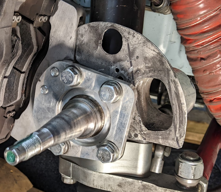
With respect: I think you're on the wrong track as a rigid assembly connected to the sprung chassis (even with flexible air conditioning duct) but then attached to an un-sprung rotating strut will fail in alloy.
There doesn't look like much strength around the aperture of the orange template and if I'm looking at it correctly it isn't designed to force air onto the rotor??? Perhaps I'm interpreting it incorrectly and you're trying to suck air out?
Is this a street legal car? If so I have no idea of the legalities.. but if it's a track only car air conditioning flexi-pipe and cable ties works pretty well for blowing air onto the rotors.
Always open to feedback.
Old one seemed to be ok for 5 + years? It's AE86 front struts so hose goes straight to chassis mount, so hose is taking all the flex. There so some pressure on the plate, but there is a tiny bit of flex in it? I am considering bracing the inlet against the strut to take any movement out of it.
Yeah the aperture is one concern i have, but i really need the biggest hole i can get. (Guess one option is to get the whole thing made out of carbon)
Air is coming in from the strut side from high pressure zone on the front spoiler through the orange pipe.Race car only, rotors are seeing sustained 600c +, this is a 267mm x 25mm disk all under a 13" rim with a 12 lap race where i'm often in traffic, so getting rid of heat is a big problem, so it needs more than your typical race car.
5 hours ago, RXFORD said:Might help to make a wireframe buck/template first. Can do it with tig wire or gas welding 'panel' wire.
Bend the wire to the shape you want, tape/tack weld them togethor, then you can lay paper over in sections to transfer onto Ali sheet.
Good idea! hadn't considered that approach.
-
1
-
-
I need to go from this hole at a 45" angle up, right and inward towards engine bay and then adapt shape to to a 2.5" or 3" outlet to attach the hose on to, space is very tight.
Orange plate will be 2mm ali, currently thinking of having it laser cut instead of doing it by hand.
What options are there for achieving this relatively quickly and potentially at home?
One I option i had thought of was to 3d print the inner and just hammer the aluminium around it, then get the seam welded (or try to do it in one piece), either way I would probably use a separate ali ring for the hose to clamp to. would end up being welded to the plate
2nd option might be the same inner but get someone to lay up carbon fibre around it (don't know anyone who does carbon fibre, or what that would cost me), but high temp area and not sure how specialised that is.
I can't see fibreglass withstanding temperature?
Any other thoughts on how to solve the problem?
-
18 hours ago, Mitch.W said:
4.9 will be great for drifting though…
would love to have a easy setup that works for grip and drift, I can get 2 different sets of front knuckles so that makes changing the alignment easy. Just always so tempted to run trs slicks but that requires big guards which makes it hard to make cool wheels fit for drifting
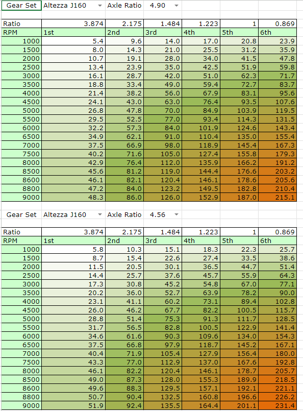
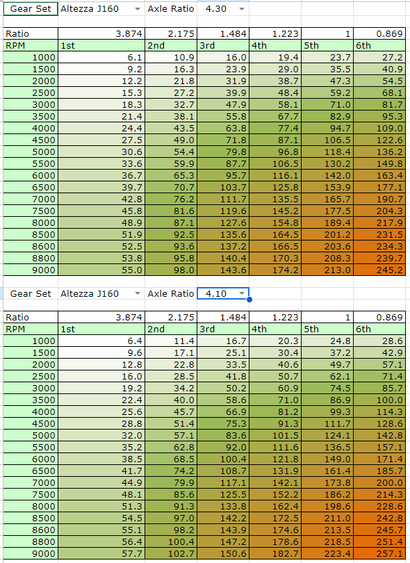
19 hours ago, Truenotch said:4.9 will be relatively short with 13" slicks. Ruapuna's straight is long - @Hyperblade can probably chime in here with the Starlet's diff ratio, RPM and 6th gear ratio to give you a better idea.
So the only TRS tyres you can still get secondhand from the series are the old rears, (now the new fronts) which need 10" wide rim, so most cars require substantial modification to run them. Those charts were based off the smaller TRS slicks that runs on 8" wide wheels. so you need to think carefully about what tyres your going to run, it may be that 15" might be the more economical option (even though I don't like the look of them on old cars)
For grip, you will be wanting to aim for 185 - 200kph at the end of the straight which should be doable with your weight and power.
I went with 2nd-6th gears which meant launching in 2nd and using 3rd for hairpin 4-5 everywhere else then 6th for straight.
But the alternative (and much nicer if you street drive) is to use 1-5th which can be beneficial for N/A cars as not using overdrive 6th.
Here's some diff/speeds (based on 54cm trs tyres) to give you an idea of where it would sit
You have lots of revs available which gives you a few options (let me know if you want me to calculate any other options).
-
2
-
-
SIL were bloody useless for me.
Try Pacific Seal the main guy is pretty knowledgeable.
-
1
-
-
On 08/03/2024 at 17:46, Tiger Tamer said:
I still haven't sorted the fuel system delivery. I had a look on K powers web site to see what they were recommending for there K power swaps.
They recommended this pump a Walbro 255L perhr pump for $255 US. Walbro 255lph HP Fuel Pump – KPower Industries
I did a google search on the pump and found I could buy the pump here in NZ for half the price in NZ dollars from this company. MSEL
and the pump price TI Automotive GSS342 255L/hr Intank High Pressure Fuel Pump Kit - Motorsport Electronics Limited (msel.co.nz)
Half the price in NZ dollars ,
I think I will be checking out K Powers recommended fuel pressure regulator as well.
MSEL are great to deal with. Shipping is slightly more expensive but it's always next day delivery. Definitely can recommend them.
-
1
-
-
16 hours ago, kpr said:
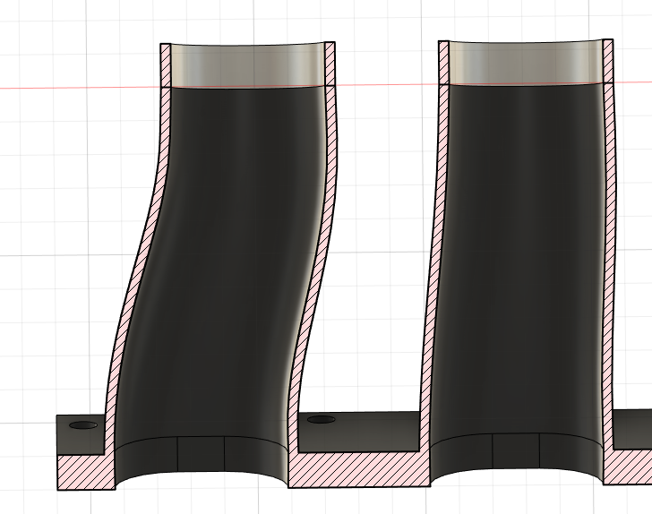
probably fine long as the bends arent super aggressive. assuming you are still using the 47mm throttles. probably best to have them on the shorter manifold, then can taper up in diameter sooner
Interestingly i just tuned a k20 on my dyno. had really short intake with big plenum and big short headers. done as expected. made 202hp and weak through the middle.
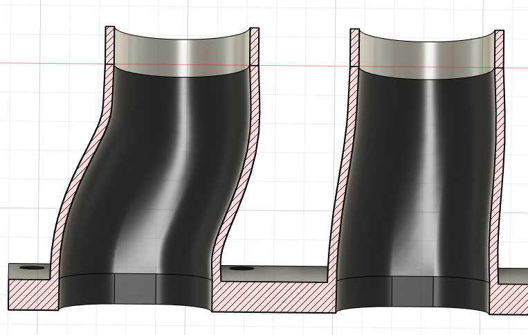
85mm long =
To me that looks to sharp on the inside of the outer runner (middle runners look fine throughout).
100mm long =
110mm long
120mm long =
5 hours ago, kpr said:Also just looking back at your vct/vvti map. seems a bit low. yours should have the 50degree vct pulley. All the ones Ive done like more advance through the middle, pretty much max it out to 50.
Yeah haven't changed pulley so will be 50 degree one, interesting, might have to end up putting it back on the dyno after the ITB's to look at all that. I have been offered the use of one, just need to upskill in being able to tune.
-
1
-
-
10 hours ago, kpr said:
probably fine long as the bends arent super aggressive. assuming you are still using the 47mm throttles. probably best to have them on the shorter manifold, then can taper up in diameter sooner
Interestingly i just tuned a k20 on my dyno. had really short intake with big plenum and big short headers. done as expected. made 202hp and weak through the middle.
48mm throttle plate, 46mm (same size as port) outlet to runner. 53mm inlet to velocity stack.
Are you going to remake the intake for it? Would be interesting to see another back to back but on k20.
-
On 23/05/2023 at 17:15, kpr said:
Yeah most people don't try anything that long, due to fitment / too hard basket in a lot of engine bays. But its really where the advantage is. when it comes to getting it dyno tuned. Id suggest having a way to try 20-30mm either way from that 320 length. is enough to see the power curve move around, to see if your in the right place. even though can shuffle it a bit with the vct , there still a litte bit to be had getting it bang on.
If going to make a plenum for it. make it big as possible. same deal with feed pipe.
Yeah kinda re the skunk2 manifold, the runner length thing works just the same on turbo stuff though. It keeps coming back to the packaging thing and being a diddle to make. shiny parts sell.
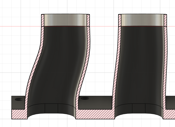
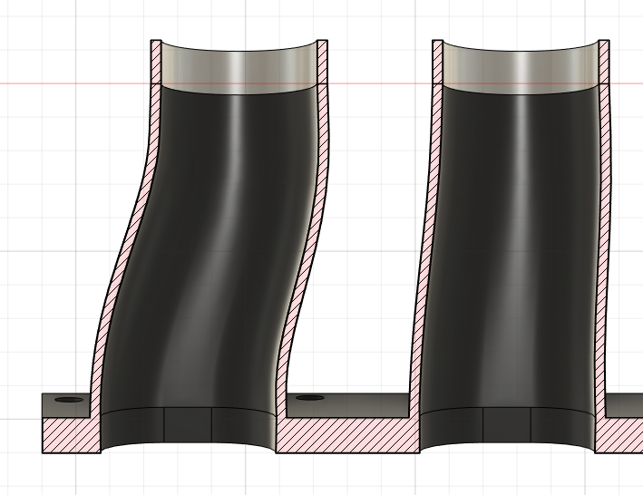
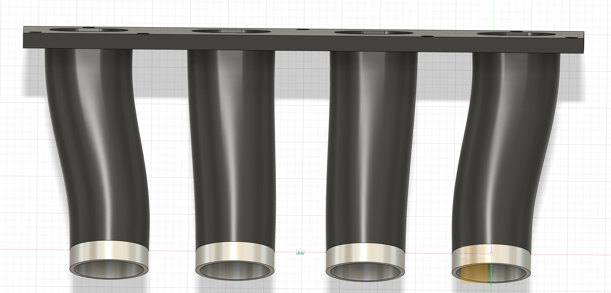
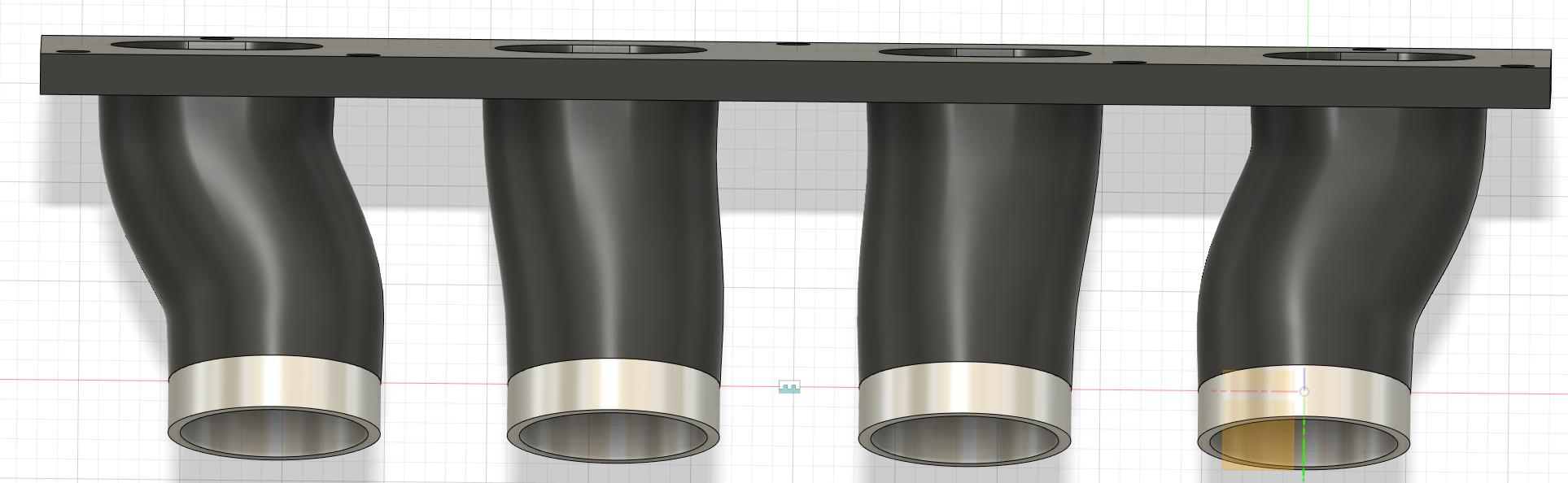
How important is getting the runner straightended up before the port?
e.g. 150mm length
vs 85mm
Obviously the longer I make them the smoother it gets, but do need to take into account velocity stacks and potentially having to go 90 degrees with them to fit the total 320mm length in.

Advice required: Making complicated brake duct out of aluminium sheet
in Tech Talk
Posted
They look good!
Unfortunately mine are fairly complicated due to the size of the rotor and wheel. It's made it challenging to get air the in, but i'm pretty confident what i've done will have a pretty big impact on temps.
First Prototype:
My original version probably would have worked with the rotor hat holes blanked off, but while i'm busy fixing those I may as well do the job properly and hopefully for the last time.