Flash
-
Posts
1,719 -
Joined
-
Last visited
-
Days Won
2
Content Type
Forums
Downloads
Events
Gallery
Everything posted by Flash
-
Spent this morning working on the MK2 version of my gear shift mock up and I'm much happier with the proposed position of the gear stick. I then disassembled the shifter one more time, drilled the first of the mounting holes in the intermediate tunnel panel and bolted the panel in for a quick test fit. The good news is that it clears my accelerator mechanism and the gear change cables look like they will clear the radiator. So now I need to take a courage pill and start cutting up my intermediate tunnel panel.

-
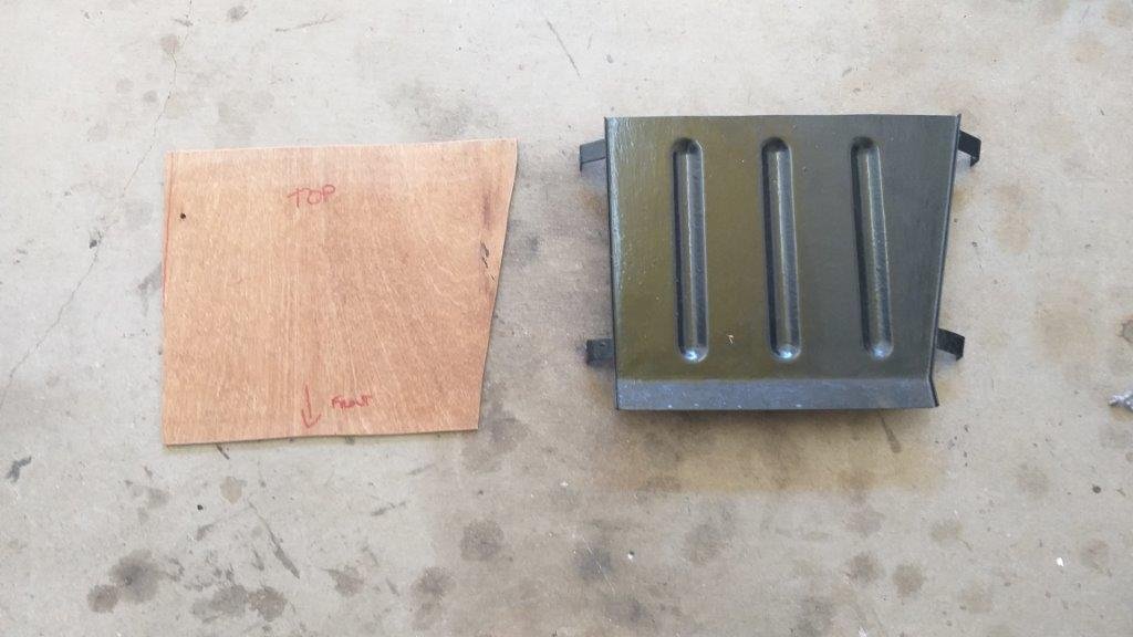
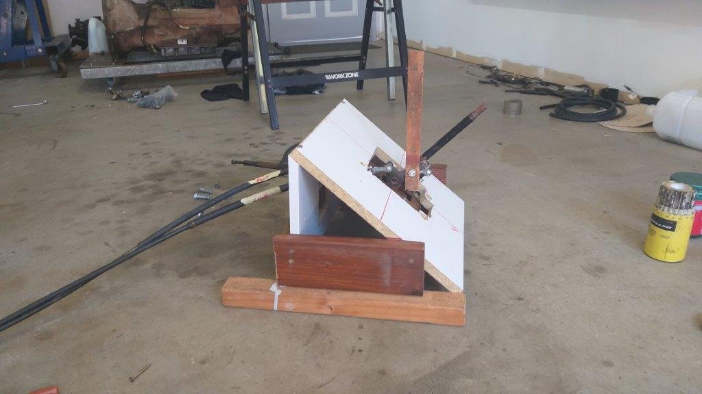
Thought I'd start the process of converting the plate, by creating a mock up in wood. This will allow me to have a few goes at getting the position of the mechanism exactly right before I start hacking up the real deal. So, this morning I put together a MK1 version. The angle of the base plate is pretty good and the cables now point downwards in order to clear the radiator core. The angle of the gear stick will need to change and also the gear stick has ended up further up the tunnel wall than I would like. All good learnings so tomorrow I'll crack into the MK2 version. Thanks for reading.
-
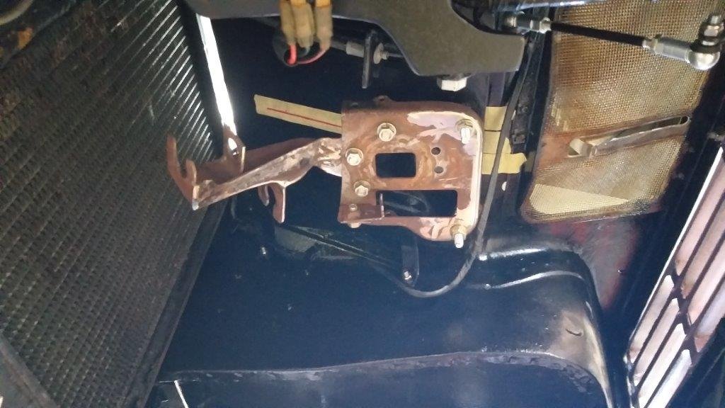
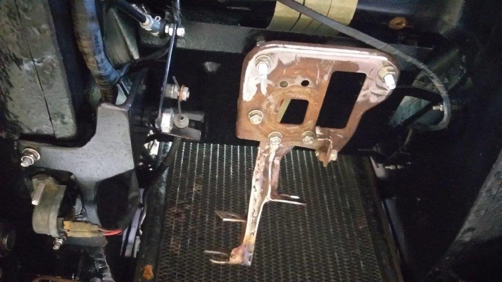
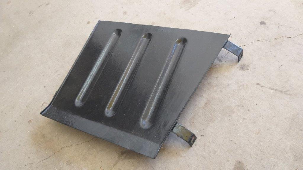
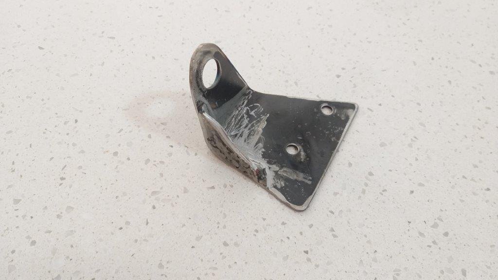
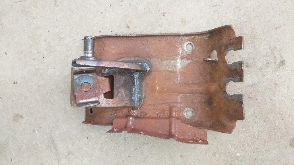
The purpose of this plate is to deflect a stream of incoming cool air over the top of the radiator. This air gets blown into the hollow void that exists between the inner and outer skin of the engine box lid. Back in the day when heat reducing materials were pretty poor quality, the propeller heads at the Dagenham Ford factory came up with this brilliant idea to use cold air drawn in through the front grill to keep the engine box lid cooler to the touch. Those who have driven a Thames in warmer climates will attest to the fact that the plan didn't work all that well. Anyhoo, since the plate is still there on my van and I have a plan to fill the void in the engine lid with heat resistant expanding foam to keep temperatures down, I figured I could re purpose this plate and use it as a mount for my floor shifter. Photo of the plate in situ:
-
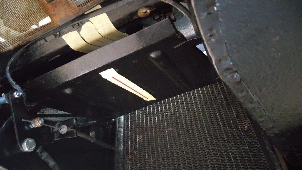
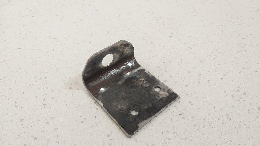
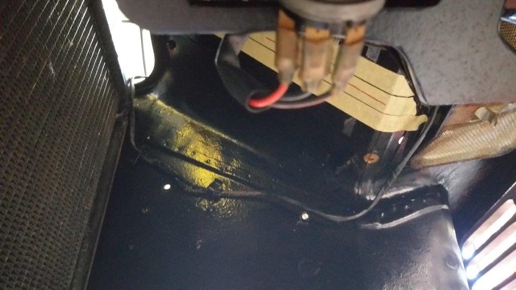
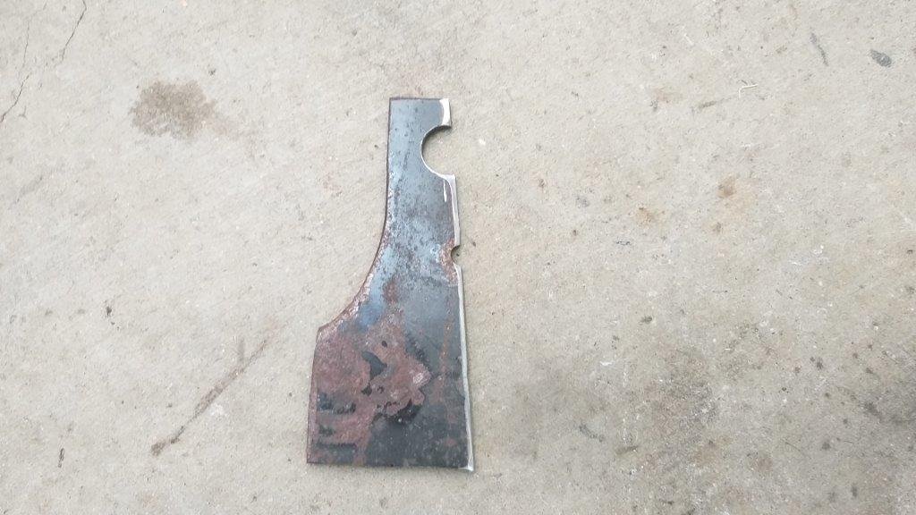
Over the past few days I've been giving some thought to how I'm going to mount the gear shift mechanism under the floor without any visible fixings from inside the cab. Then in the wee hours of this morning I had a eureka moment. Running up underneath the angled front wall of the engine box is a second steel plate that looks like so:
-
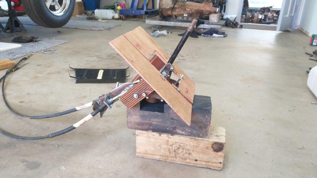
Even although I'm 100% happy with the shift operation, I still need to work out how I'm going to mount the bloody thing. My OCD tendencies will not allow for any fixings visible from inside the van and there is also no way I'm cutting a ruddy great hole in the Thames, until I've got the mounting sorted. So in my first step towards finalising this I proceeded to make a wooden mock up of the tunnel wall complete with replicated wall angle .... yep its a sad, sad life I lead. I've just clamped the shifter base to the inside face of the slope for now, but my plan is to drop the back so that the cables will face downwards and that should bring the gear stick back to as close as possible to vertical as currently indicated by my rusty old flat bar, but that is for another day. I'll need to extend the gear stick anyway so it should be easy enough to incorporate a bit of a bend if needed I admire your staying power if you've managed to reach this point in my story without falling asleep. Till next time.
- 740 replies
-
- 12
-

-

-
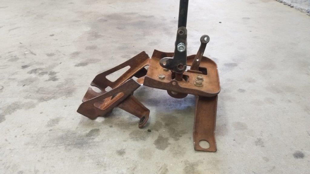
Chucked everything back together and crawled under the van to check clearances. All looking good. Made up and mounted some permanent outer holders for the gearbox side - my 3rd or 4th set to date as I'm using existing chassis holes because ... OCD. Gave it all another test and I'm happy to report that I'm getting consistent results. Got Mrs Flash to give it a go too and she is a very happy lady. Happy wife, happy life, so its on to the next step.
-
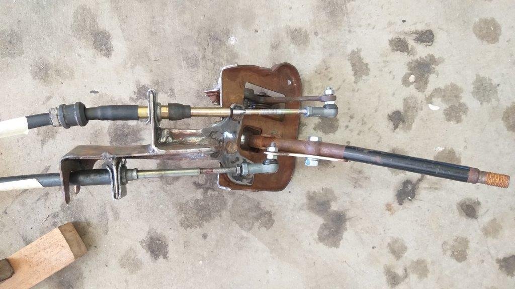
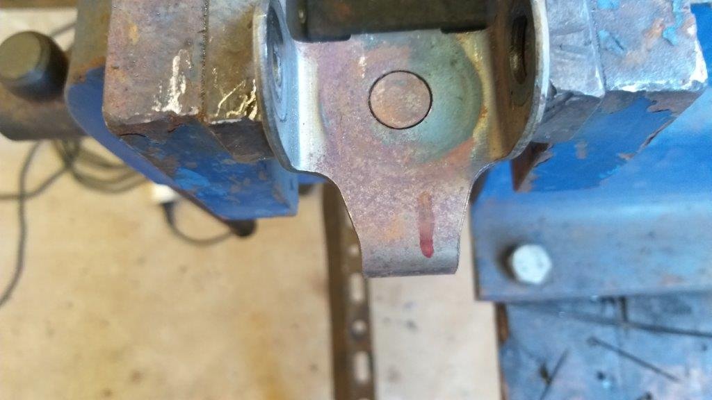
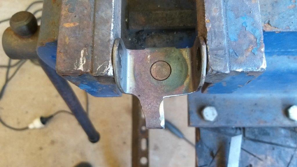
Okay, so on to making the mechanism a bit more robust. A bit of metal carving and a few tack welds and I'll let the photos tell the story. Still looks a bit nasty and I cocked up one of the holder brackets the first time around, but I'll trim that off when I tidy the whole thing up. For now I just want to prove the functionality.
-
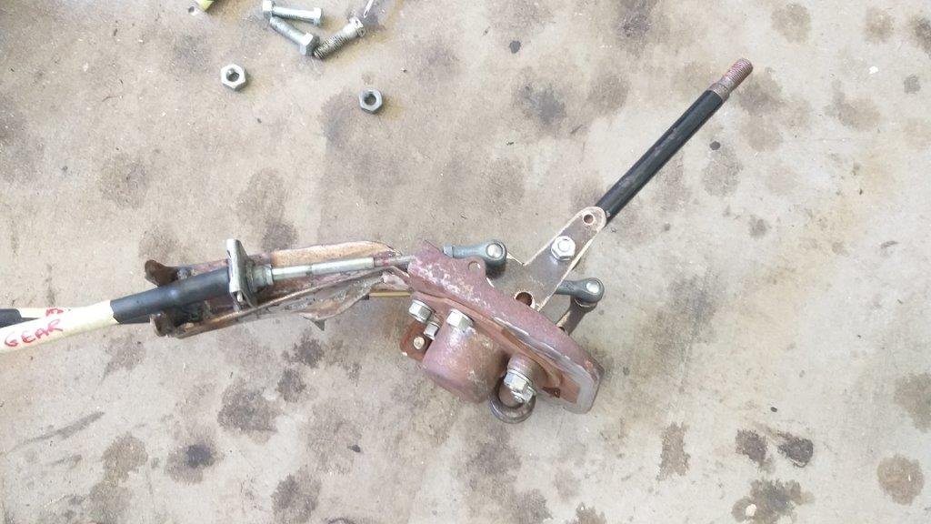
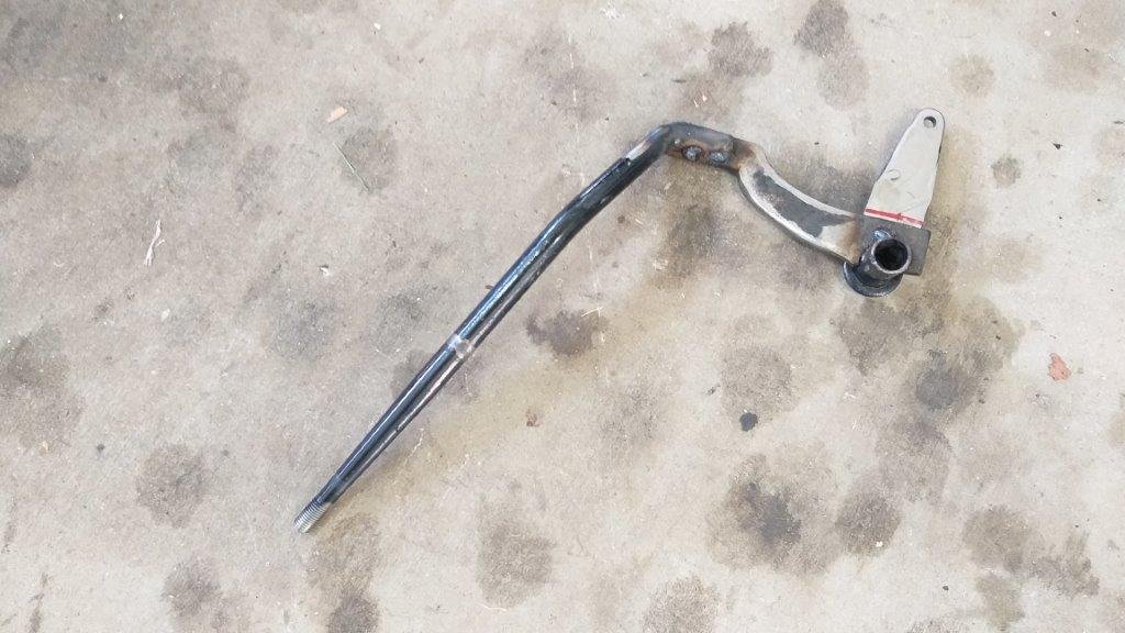
The first challenge is that there isn't enough space to mount the shifter complete with cables as the cables clash with the radiator core. Gave it a bit of thought and decided to try angling the cable holding section downwards to allow the cable to clear the radiator. Quick cut and bend to prove the concept. Looks nasty and its flimsy as hell. Chucked the cables back on and put it through the gears and it still works smoothly. So far so good.
-
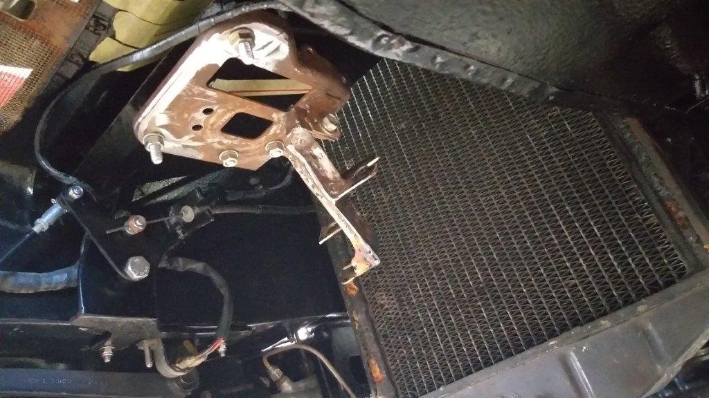
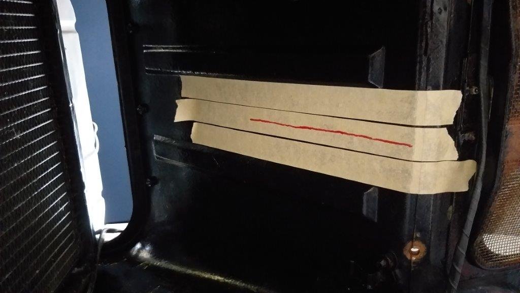
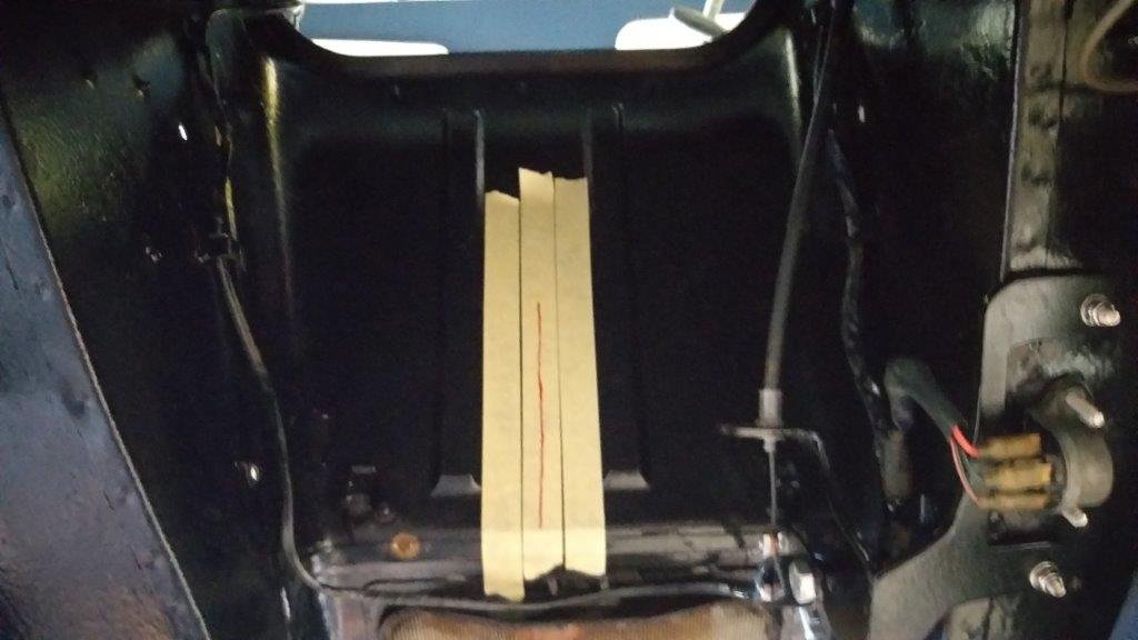
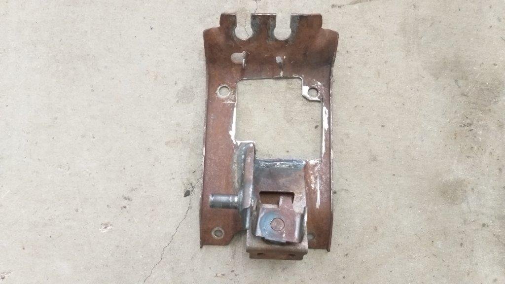
The eagle eyed amongst you would have noticed that the front wall of the engine box rises from the ventilation flap at an angle. The reason for this is that looking from underneath the van it creates a little tunnel that funnels cold air from the front grill to the radiator that is mounted in the engine box forward of the engine itself. So in essence I've got a little triangle of space that measures about 250 mm long by 350 mm wide. View from underneath with centre point marked up in tape.
-
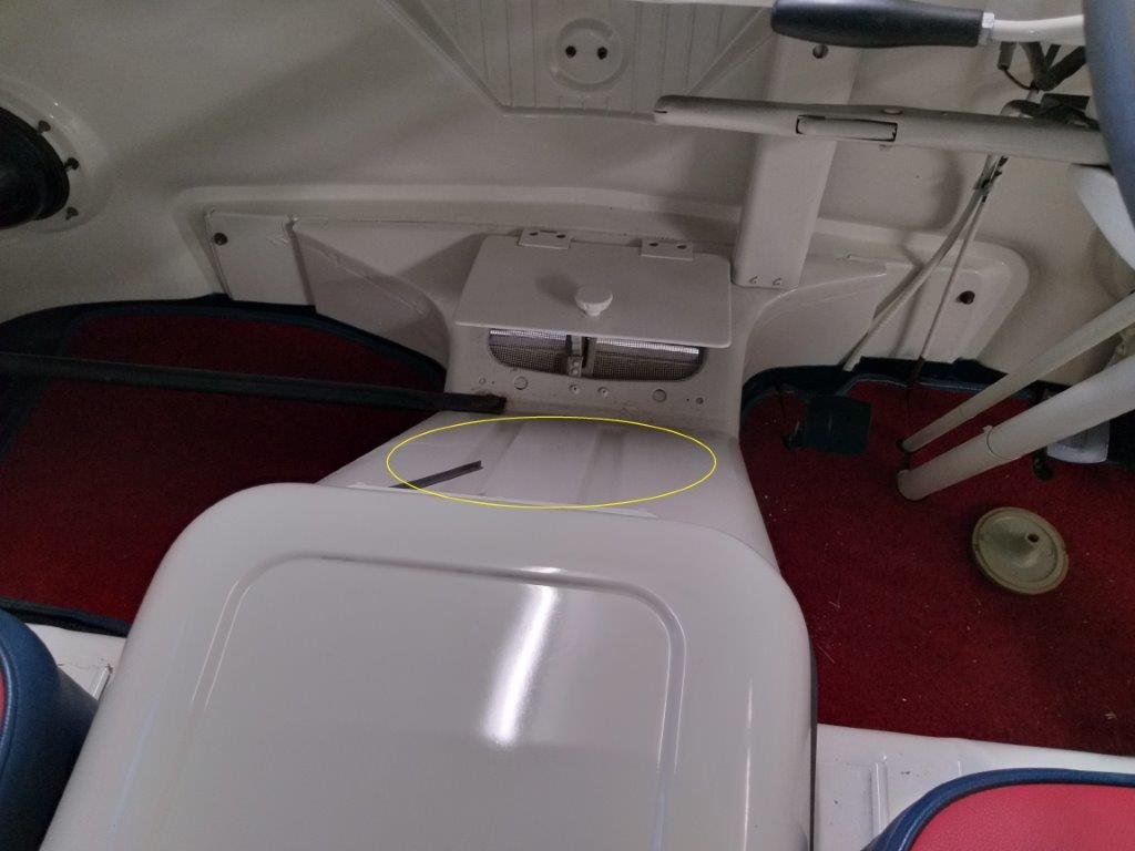
In the Tarago the gear stick mechanism sits inside the van and is covered by a plastic console. My plan for the Thames is to hide the mechanism underneath the floor with just the gear stick poking through and surrounded by a rubber gaiter. In this way I'm hoping to to keep the cabin looking as "old school" as possible. Sounds easy enough, but the floor space available is pretty limited and ii is not without its own set of challenges. The only available real estate is the area circled in yellow:
-
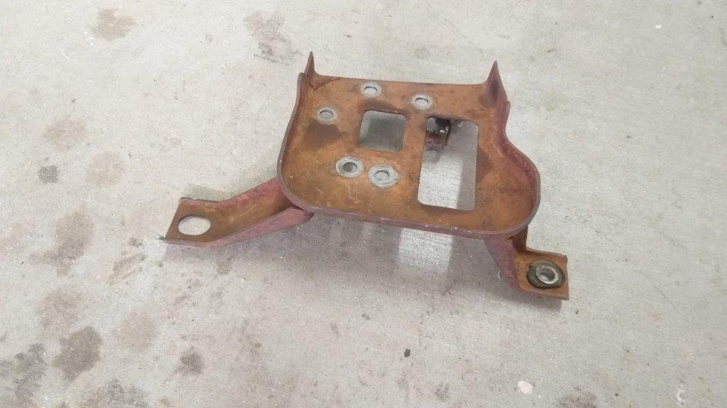
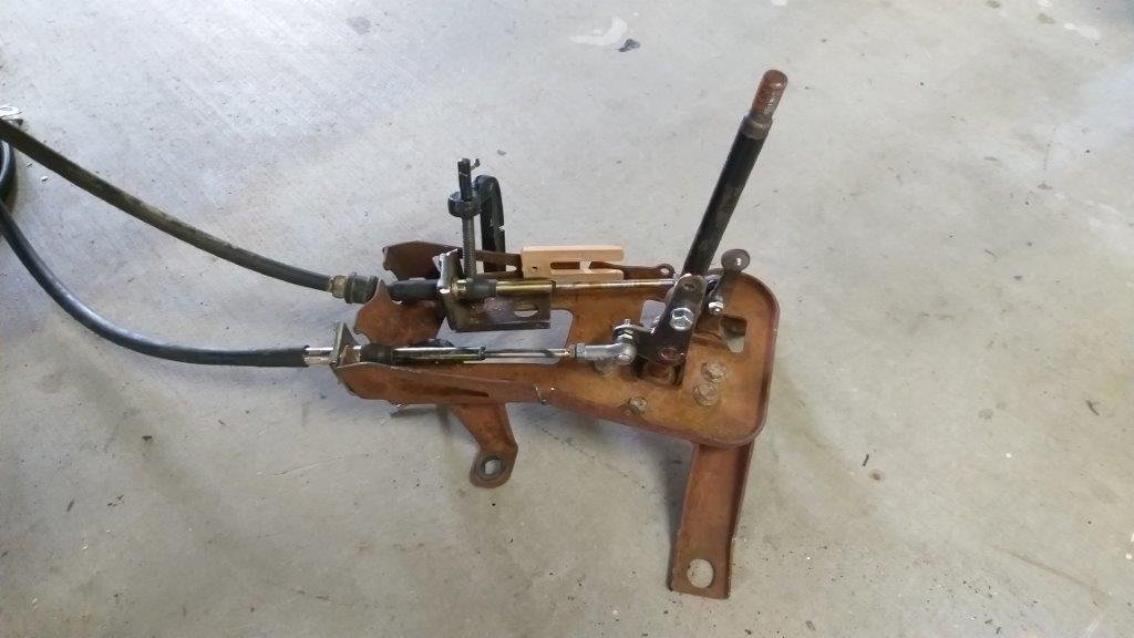
For the next version of my floor mounted gearshift I'm going to use the shifter out of a mid '90s Toyota Tarago that I sourced from my local wreckers. The good thing about this shifter is that the linkages work in the direction that will provide me with a standard shift pattern using a shorter set of Morse cables. So the first thing that I did was to throw my cables on the loose shifter using some temporary clamps and other bits and bobs to fix the outers in the correct positions. With the other ends of the cables attached to the gearbox - again using temporary holding brackets for the outers - I proceeded to put the new shifter through its paces. Despite it looking a bit like a dog's breakfast the first test results were pretty positive with the gear stick consistently returning to the centre gate when dropped back into neutral. So far so good.
-
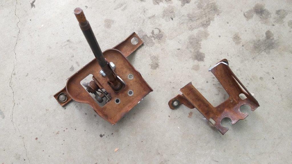
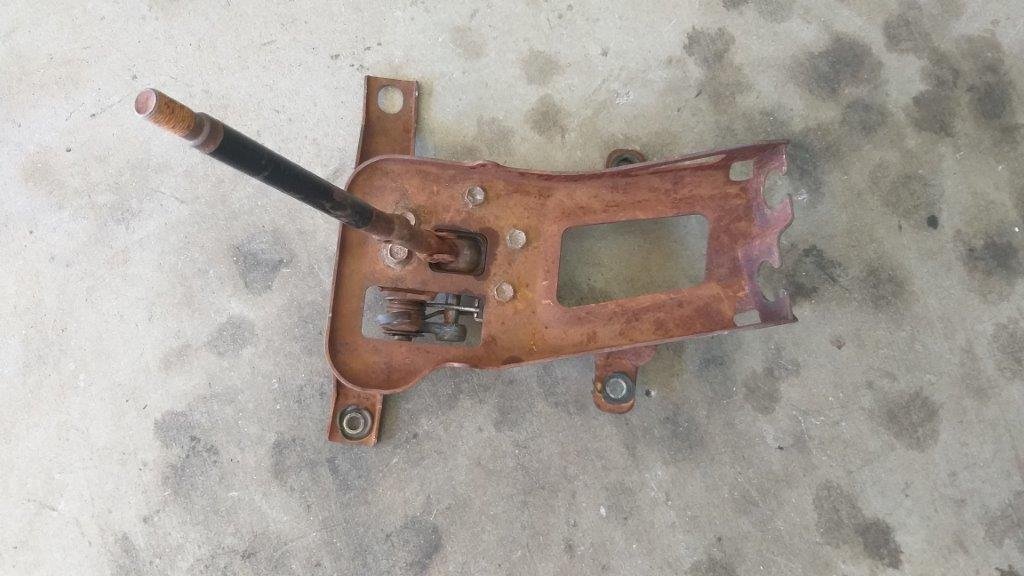
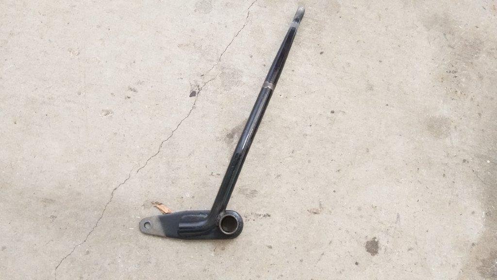
Assembled it all and ...... ........... another fail. Waaayyy to much movement at the business end of the gear stick. Selecting gears felt a bit like stirring porridge and I'd be likely to poke my passenger in all kinds of intimate places whilst trying to select gears. So, after sending the well butchered Express mechanism to the naughty corner to let it think about what it had done wrong, I moved on to my next plan of attack, which involves this crusty looking bit of kit that I sourced from my local wrecker for the princely sum of $20.
-
and more :
-
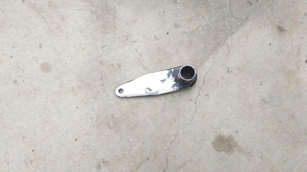
A good few years ago a mate of mine had a lawn mower that broke down. After heading into town and buying a new one, he came home and proceeded to fix his old one. Well now that I have my two auto gearboxes safely tucked away in the corner of my shed, I'm now feeling a bit like my lawnmower mate as I'm moving forward with renewed vigor to get the manual gearbox working correctly. Sad, I know, but at least I've secured a fall back position should everything turn to custard with the manual and all it cost me was a tank of fuel and some other junk manual parts that I had lying around. So back to the manual gearbox. By now you are all sick and tired of hearing me rabbit on about my battle to get the original Thames column shifter to work with the Toyota 5 speed. I can get it to work, but it's just not smooth or consistent enough for my liking. All it's going to take is one miss shift at revs or speed and it will all end in tears. Mrs Flash has given it a few test goes and has declared that she is reluctant to drive the Thames as is for fear of scrambling the box. So that leaves me with either doing the conversion to auto or doing a floor shift conversion on the manual. A while back I tried the floor shifter out of my Mitsi Express donor van. Because of the way the shift mechanism worked I had to use long Morse cables that I looped around to get the shift pattern correct. While this worked okay the "latency" in the long cables meant that the "gate wouldn't automatically return to centre when in neutral. I was able to remove this latency using shorter Morse cables, but this resulted in a reversed shift pattern. Not ideal at all. So earlier in the week I decided to try modifying the Express shifter to provide a normal shift pattern. My cunning plan was to mount the mechanism upside down and then rotate the gear stick by 180 degrees. So got out my grinder and welder and I'll let the pictures tell the story
-
Thanks for the suggestion. When I first started piecing together the steering/gear change column I discounted the HiAce option, but there has been a lot of water that has passed under the bridge since then. So, yes you have raised a very valid suggestion and it might be worth my while dragging the HiAce one out for another look. All it's going to cost me is a bit of time. I really appreciate your input. Sometimes its difficult to see the wood for the trees, so its good to have a fresh approach suggested.
-
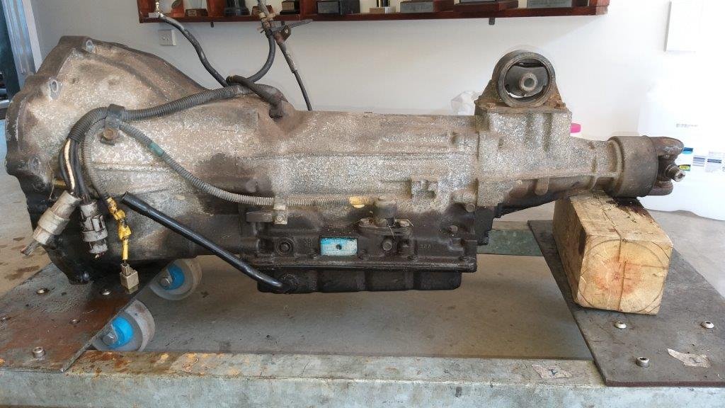
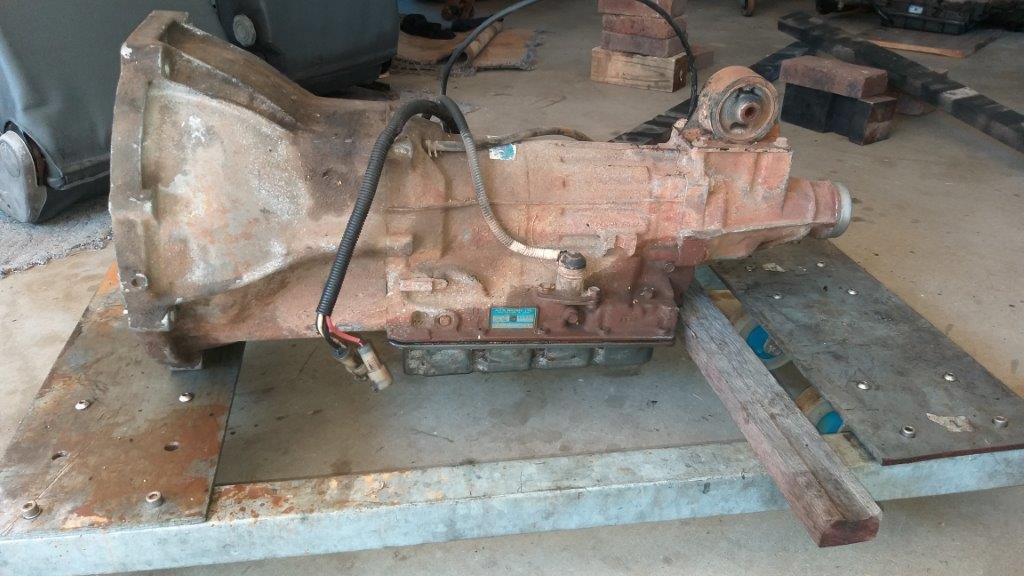
You know that things have slowed down a bit when it is almost two months since my last update. To be fair most of my free time has been taken up sorting out other members of our vehicle fleet. Needless to say I've missed working on the Thames and I really need to get back on it. So my last Thames related update was all about the challenges I was facing trying to get the Thames column shift to work properly with the 5 speed Toyota gearbox. In one of my updates I was even considering fitting an automatic gearbox if I could find one. At the time I asked for some advice on the Tech Forum page and the general recommendation was that I should be hunting for a A44DL auto box out of the mid 80's HiAces as this would be equipped with a Y bell housing to match the Toyota 3Y engine that I am running. At the same time it was pointed out that these boxes are getting pretty thin on the ground. Anyway I have been keeping an eye out for an auto and about a month back I was swapping a few yarns with a fellow Queenslander on the Book of Faces and he happened to mention that he had a few spare auto gearboxes lying around for his Y powered HiAce camper. After a few messages back and forth a deal was struck. I would swap him a 4 speed manual complete with flywheel, pedal assembly and clutch hydraulic pipework for two A44DL auto boxes. On Tuesday morning Mrs Flash, the hound and I loaded all of the manual stuff into our modern daily van and headed off into inland Queensland to visit my new FB mate. After a round trip of 878 km, I now have two auto boxes languishing in my shed. Both are 0372L models but one has the Y bell housing and the other the newer RZ bell housing. Apart from the bell housing difference the only other difference between the two boxes is the position of the dip stick outlet on the oil pans. The RZ has the dipstick on the opposite side for some reason. First prize is still to get the 5 speed manual to work, but at least if it all turns to custard I now have a fall back position. Photos of my two new boat anchors : Thanks for reading.
- 740 replies
-
- 12
-
-
Thanks for the suggestion. I've got a few spare engine earth cables lying around. Should be easy enough to fit an extra for peace of mind.
-
Yep, the bellhousing one on my Moke goes straight to the body. It's the flat braided coppery looking type. I cleaned up both ends and even took the fresh paint off the body under the fixing bolt. It broke my heart to do it, but in the past I've experienced earthing issues through fresh paintwork which took me forever to diagnose. Good tip about the jumper lead, so thanks for that. I'll give that a go and recheck voltages just to make doubly sure my earth strap is good.
-
Yeah, I was reading your build update this morning and noted the improved voltages you achieved with your upgrade. Bloody good outcome, so well done. I'm getting 14.28 volts across the battery when the engine is running. Its been upgraded to an alternator with internal regulator so I can't complain about those results.
-
Good advice. Much appreciated.
-
Thanks Tory, it's been upgraded to an alternator.
-
Okay Team, Some interesting results from further testing that I carried out this morning. So as a bench mark I used my multi meter to check a few voltage readings across the Moke's 325CCA battery : Moke battery at rest - 12.96 volts across the terminals (so still showing the benefits of the night before last's trickle charge) Moke battery under cranking - 10.13 volts across the terminals Moke battery under cranking - 9.57 volts at the coil's + wire I then removed the Moke battery and chucked in my 9 month old ute 650CCA battery: Ute battery at rest - 11.94 volts across the terminals Ute battery under cranking - 10.15 volts across the terminals Ute battery under cranking - 10.10 volts at the coil's + wire I then plugged the coil's + wire back into the coil and attempted to start the Moke using the ute battery. It fired up almost instantly, something the Moke has never done during my 4 year ownership. Its always needed around 20 seconds of cranking before it would fire. So it looks to me like the electronic unit inside the distributor is a lot happier when it receives a higher voltage. Does a 1.8 volt loss during cranking sound excessive ? Or should I just replace my existing 4 year old 325CCA Moke battery with a brand new higher rated battery and calling the job done ?
-
Thanks to everyone for the additional info shared. I'm going to chuck the battery from my ute into the Moke first thing in the morning and see what voltage I get at the coil during cranking. The ute battery is less than a year old so I know its a good one compared to the one currently in the Moke which was already installed when we bought it almost 4 years ago. It's got no date stamp on it so I've no idea how old it actually is. Talking about the Moke battery I see its rated at 325CCA. Does this sound about right ? If I'm still getting low voltage at the coil even with the good battery then I'm thinking it might be my starter motor that is getting a bit tired and might be sapping to much energy from the battery. I've already cleaned up my battery connections, all of my earthing points and the connections on my solenoid and starter motor, so I'm pretty confident that its not a wiring related issue. I'll report back in the morning.
-
Thanks heaps to everyone who has responded thus far. So I'm thinking the next step should be for me to check the voltage across the battery whilst cranking the starter. If its around the 9 volt mark then its probably in questionable condition. If that's the case I might just connect up a good battery from one of my other cars and see if that resolves the issue. I'm also starting to wonder if I should be replacing my old GT40 coil with something else.
-
Ta for running that test @nominal. I should have checked the voltage across my battery when cranking. I'll do that next time I'm out in the shed.