Flash
-
Posts
1,719 -
Joined
-
Last visited
-
Days Won
2
Everything posted by Flash
-
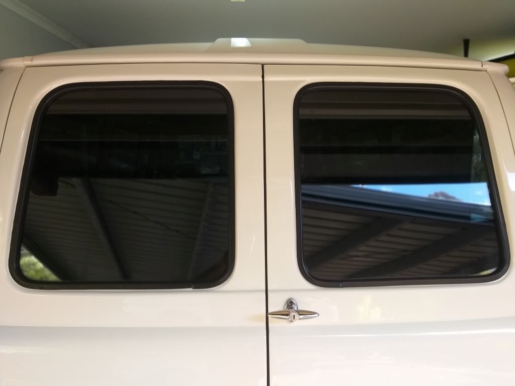
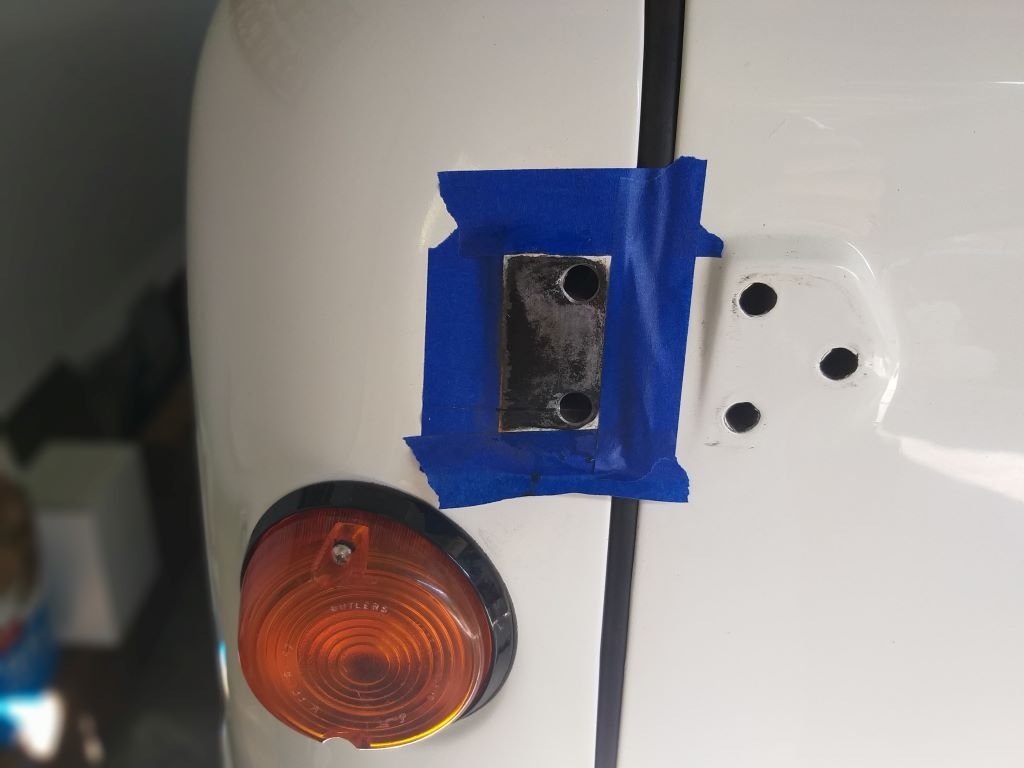
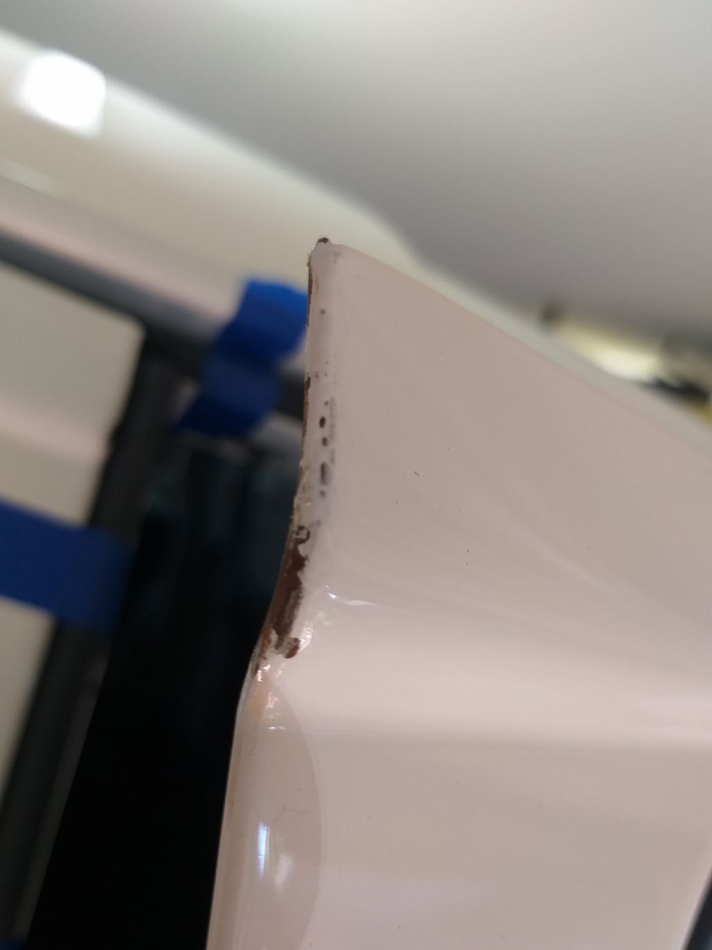
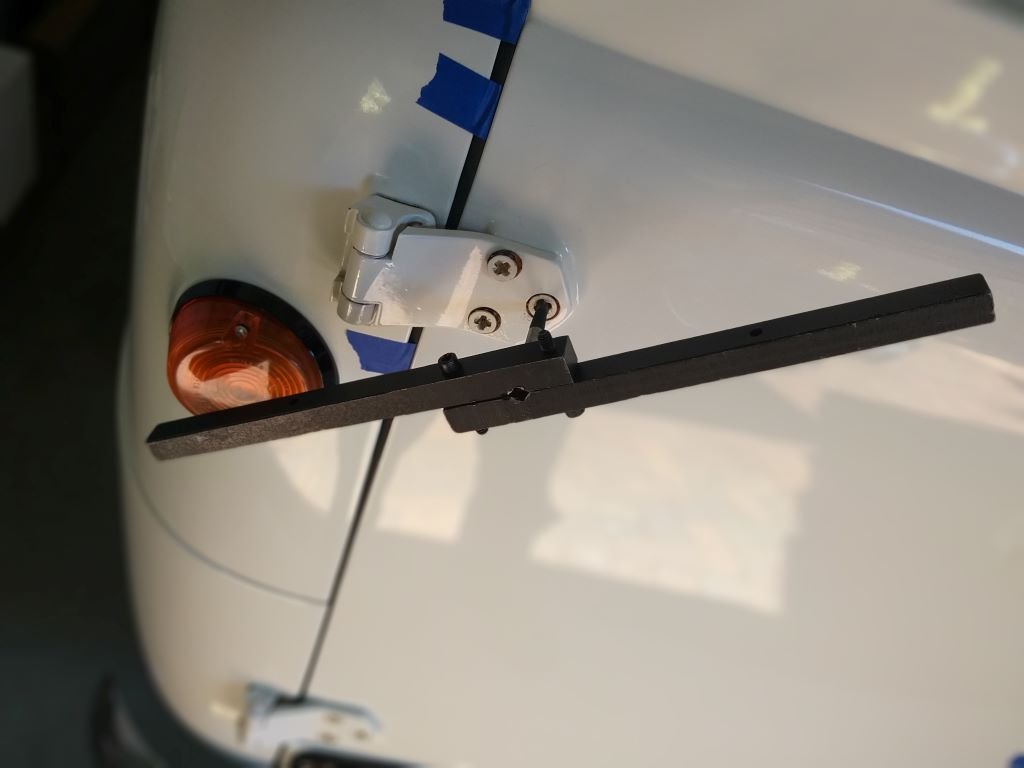
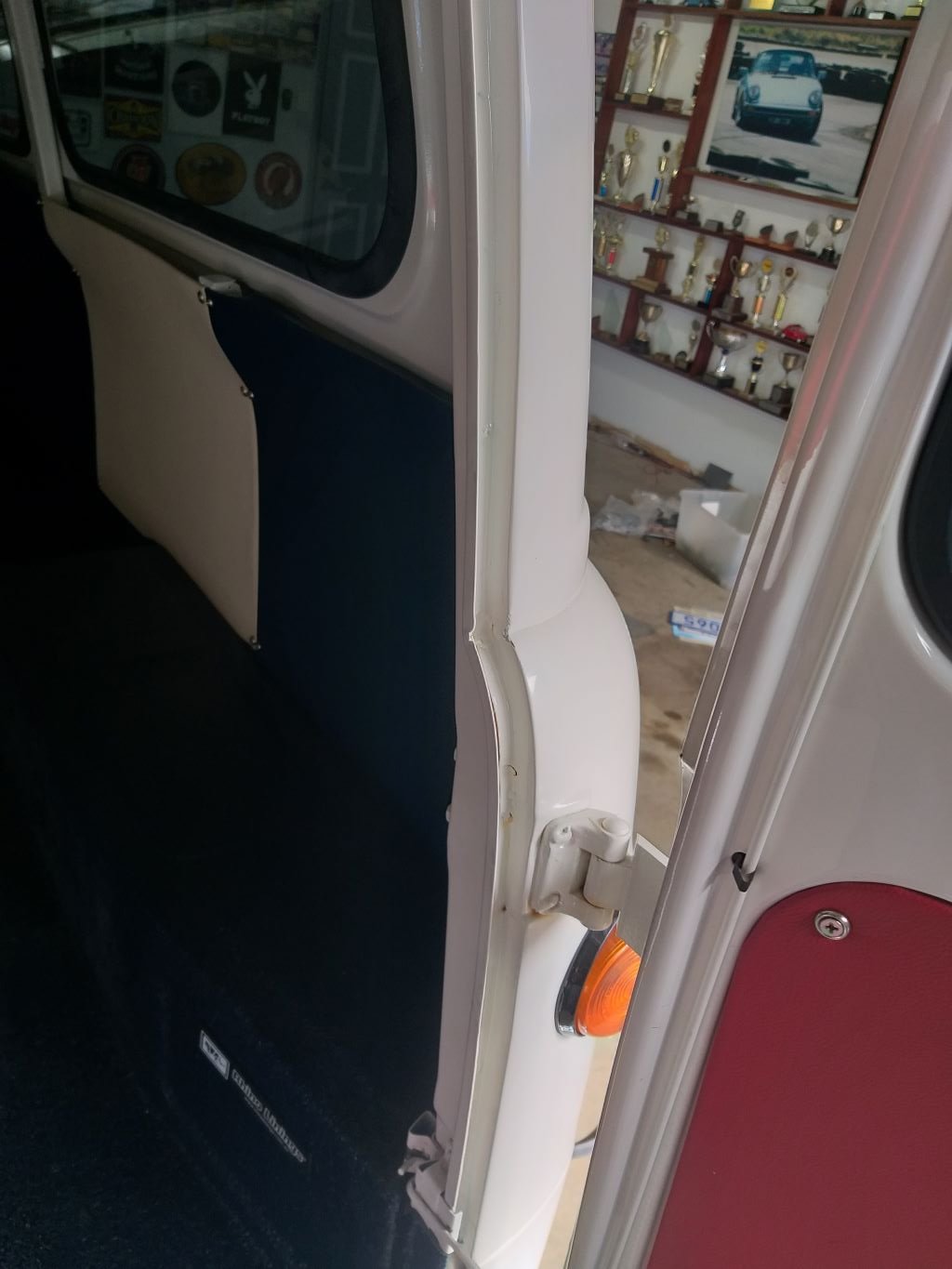
Rear door alignment - Chapter 3 I had to elongate the mounting holes in the body in order to move both top hinges out slightly. But after a bit of fiddling about I'm much happier with the door gaps and the top corners no longer touch, so I'll take the win. Luckily, I've got some touch up paint, so I'll give the grazed corners a go, but that's for another day. Thanks for looking.

- 740 replies
-
- 15
-

-
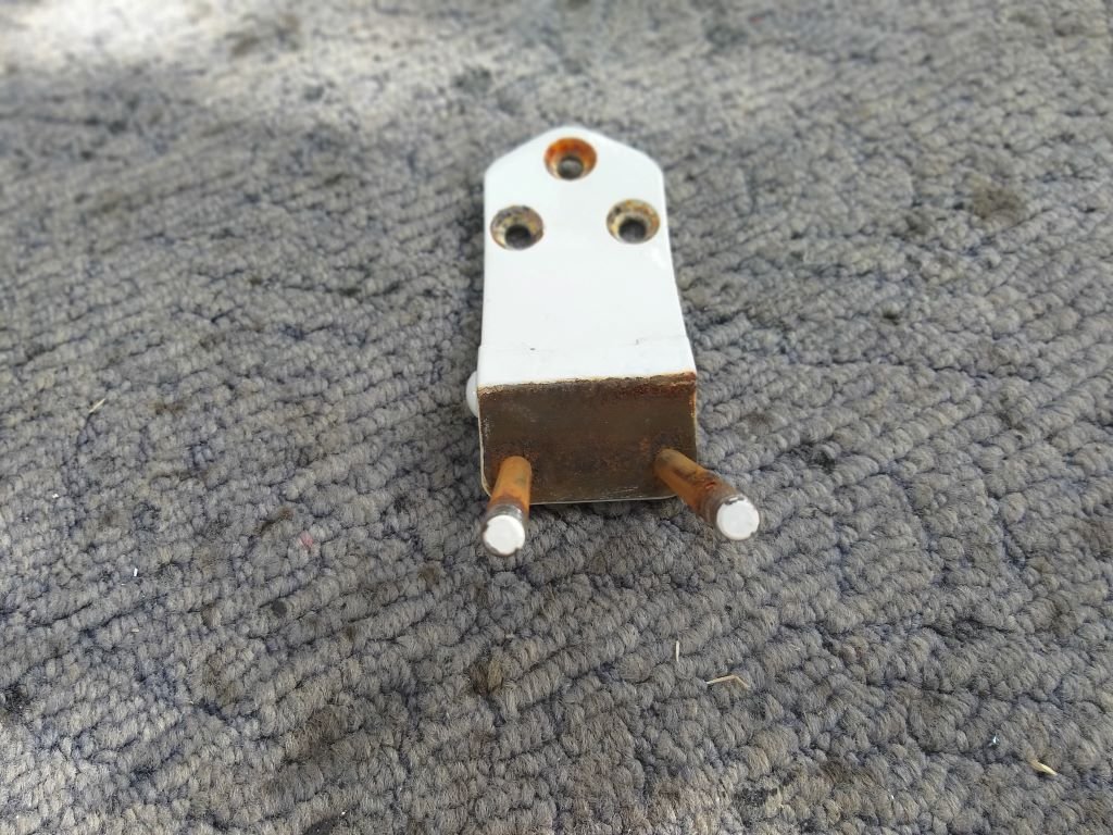
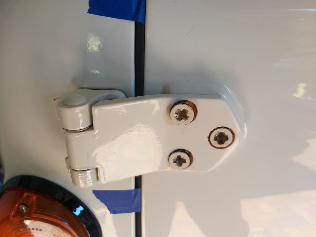
Rear door alignment - Chapter 2 Removing the hinges revealed that the painters had left bare steel under the mounting surfaces ... nice. Gave it a bit of a scuff and a splash of rust converter and did the same to the back of the hinges.
-
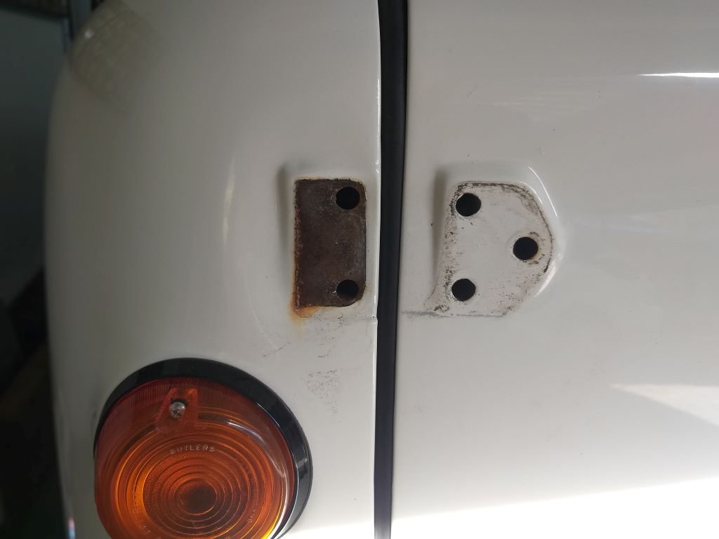
Rear door alignment - Chapter 1 While I'm focusing on the rear barn doors, I figured it was time to see if I could sort out the door gaps. From day one they have been all over the show with signs of rubbing on the two top corners where the doors meet. Now in hindsight this job would have been much easier without having to fight against new rubber seals that still need to bed in, but it's too late for that now, so I just had to crack into it. First step was to loosen off the old door bolts. I hate these things with a passion as they always look crap with bits of flaking paint and weeping rust and the star heads make them a real bugger to get out if they haven't been moved in a while. Long term I'm thinking I'll do the same as I did on my Bedford van and replace them with stainless steel machine screws, but that's for another day. So as is typical with these things all but one of the bolts backed off okay. Ended up having to use an easy out for the last bolt. Did I mention how much I hate these bastards.
-
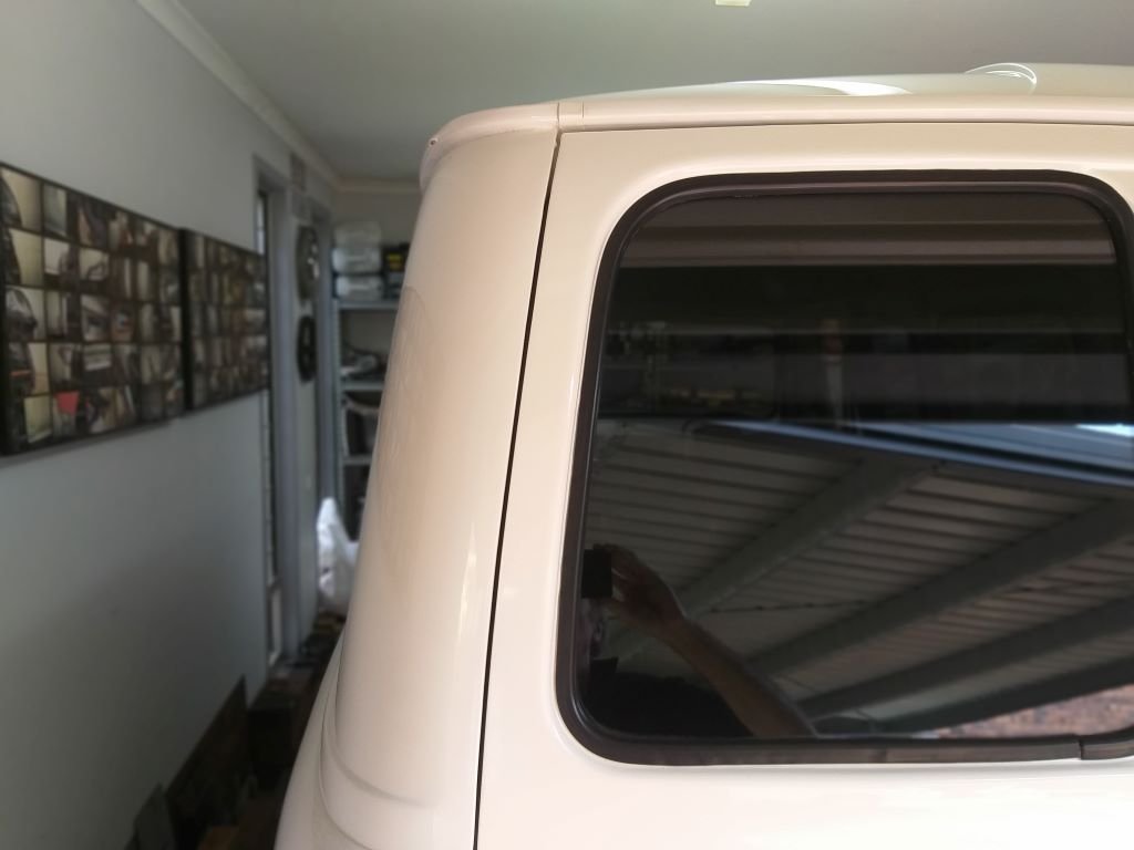
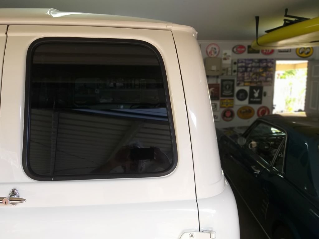
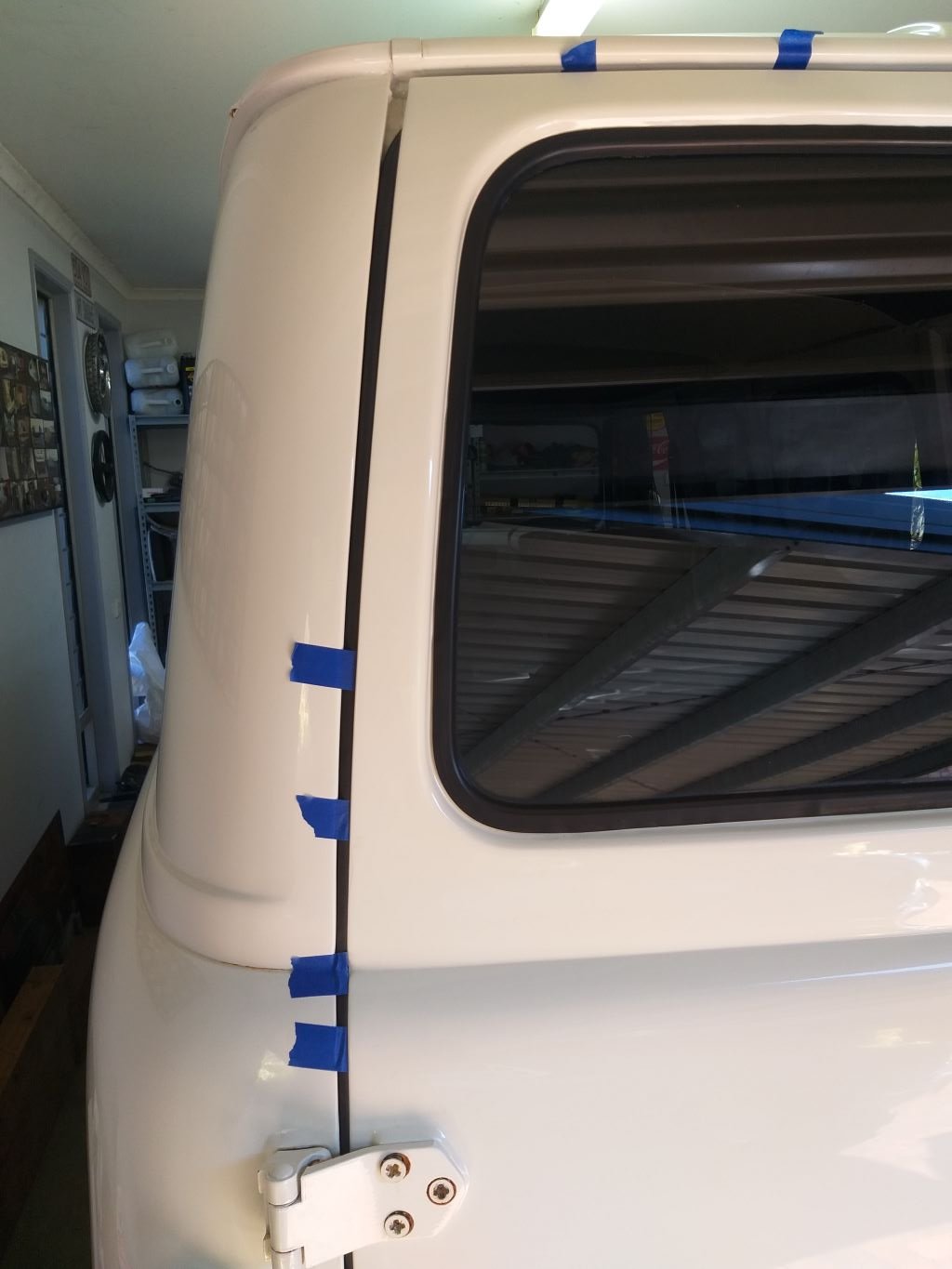
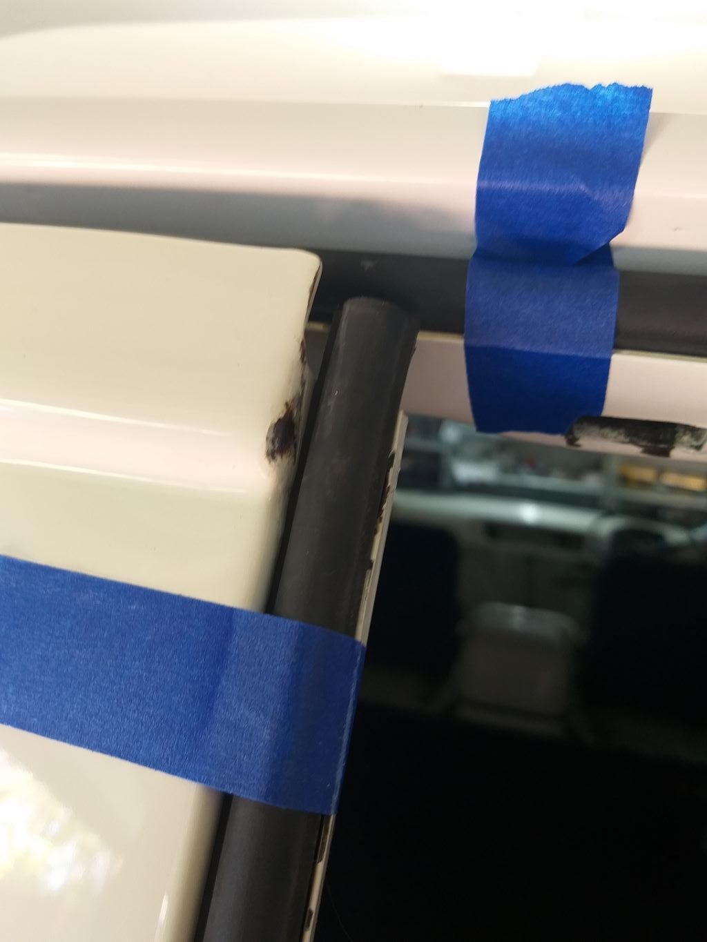
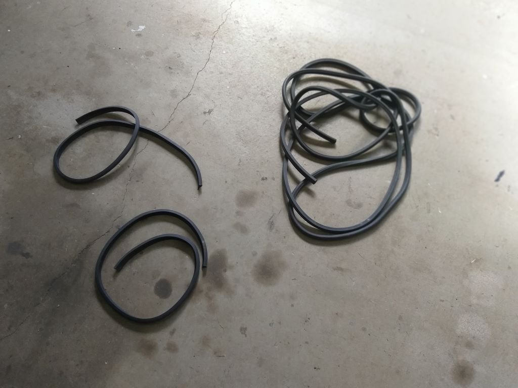
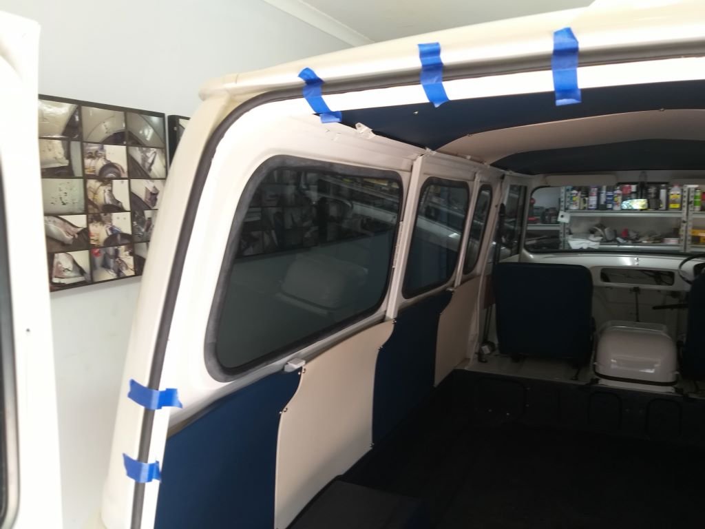
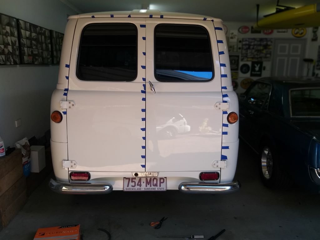
While cruising around the neighbourhood I couldn't help but notice how rattly the rear barn doors are. Then when I gave the old Thames a bath the other day the back was absolutely saturated, so I figured it was about time that I fitted some rubber seals. that will hopefully solve both issues. I rummaged around in the box of spares that came with the van when I bought it and sure enough there was a length of seal with what looked like the perfect profile for the job. Offered it up to the door surround channel and it was perfect. Only downside being that it needed gluing into the channel. Yuk, not my favorite job. Anyway, took the bull by the balls and armed with a tube of contact adhesive and a few other bits and bobs, I cracked straight in. I'll let the glue go off overnight and can then strip the bits of masking tape that I used to hold the seal in place. Thanks for looking.
-
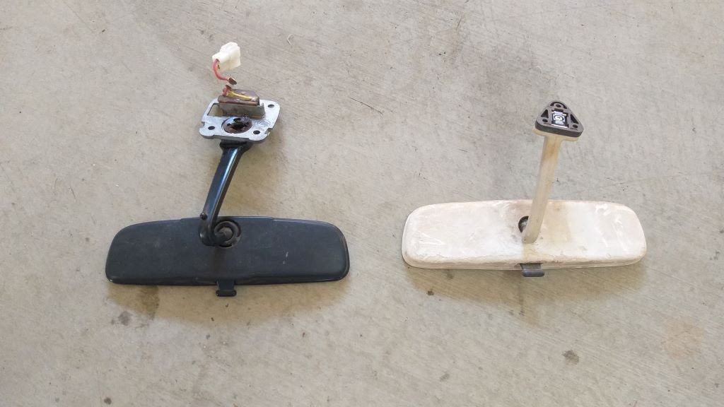
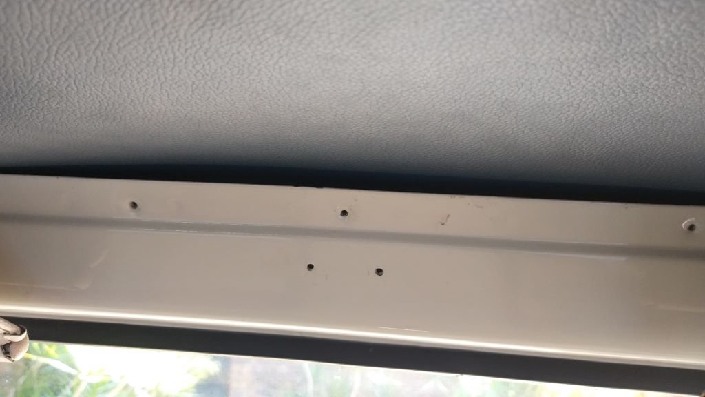
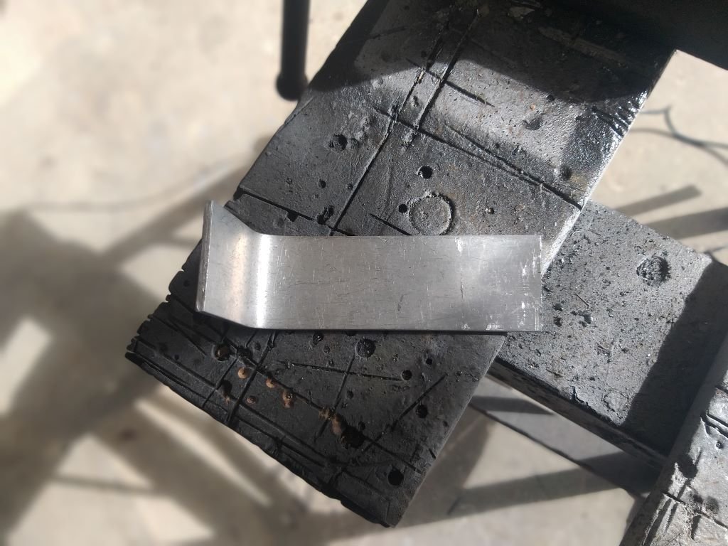
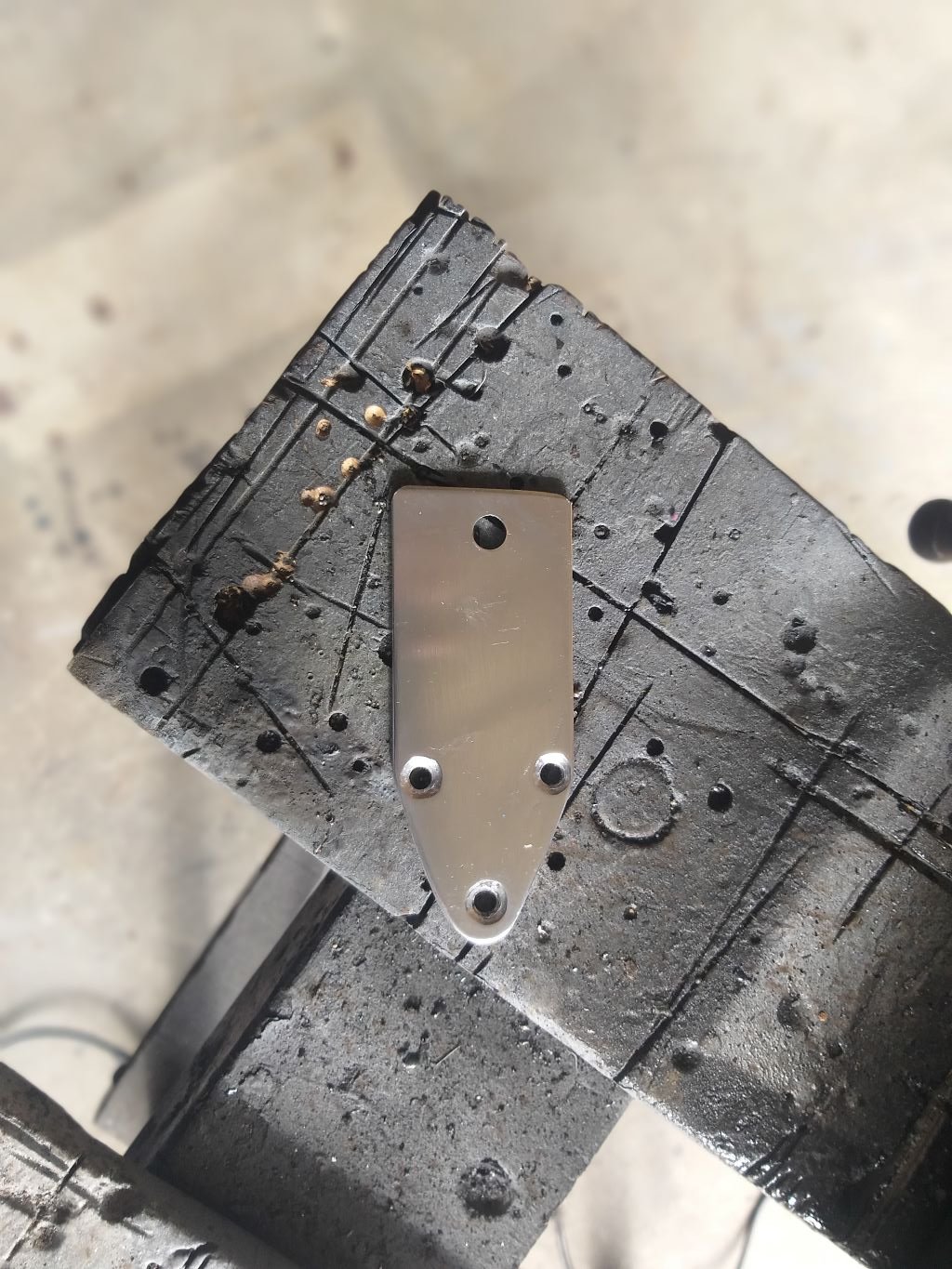
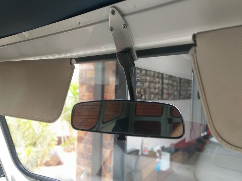
It's a bit disconcerting driving around without an internal rear-view mirror, so I dug through my spares pile and found two likely looking candidates. I chose the black backed one as it is in better condition than the flaky looking brown one. First step was to remove the little interior light from the mirror stalk as it won't work for my setup, and I then offered up the mirror to check fit. Drats, the stalk is too short so I'm not getting a view through the rear windows. Dug around in my scrap pile to see if I could find something suitable to extend the mount. Found a little aluminium offcut that looked like it would work. Managed to poke some holes in the offcut that lined up with the Thames' existing mounting holes, then shaped the offcut so it is more pleasing to the eye. Was going to give it a splash of satin black, but then decided to polish it up instead. Works well and doesn't look too out of place. Bonus is that the extended mount gives me heaps of room to build an overhead console which is planned for further down the track.
- 740 replies
-
- 16
-
-
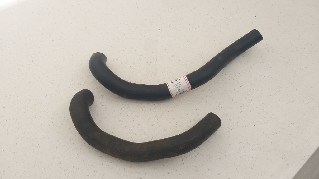
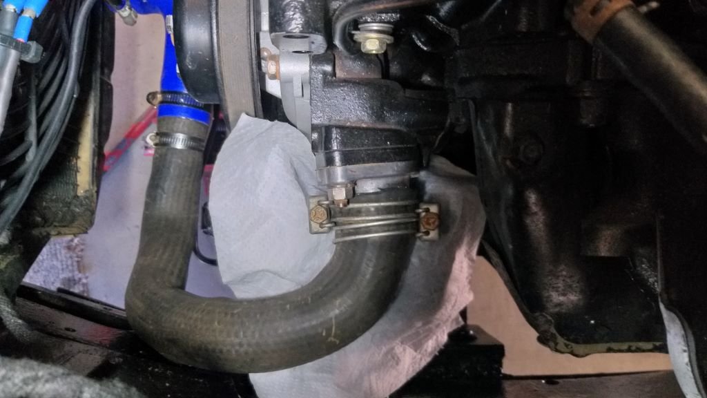
Now that I've cured my water leaks it's time to drain the water and fill the system with coolant. Thought I'd best replace the second-hand radiator hose that I was using for mock up purposes with a fresh one. Only problem is I couldn't remember which donor van this hose came from. I had a suspicion that it was from the newer Express van, so yesterday while I was in town to fetch the new wheels, I did the tour of my local parts shops with my sample in hand. Turns out my suspicions were correct. It's a slightly butchered lower radiator hose off a 4G63 powered Mitsi van. Trimmed it down this morning and clamped it up before adding some liberal splashes of coolant to the system and it looks like I'm good to go.
-
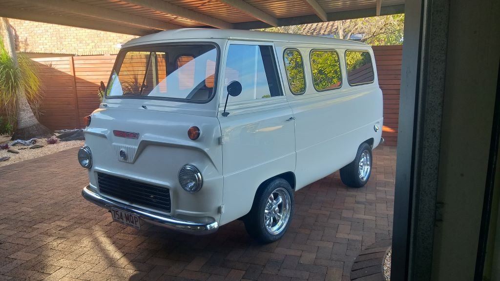
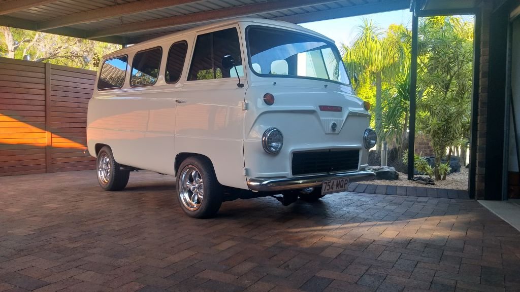
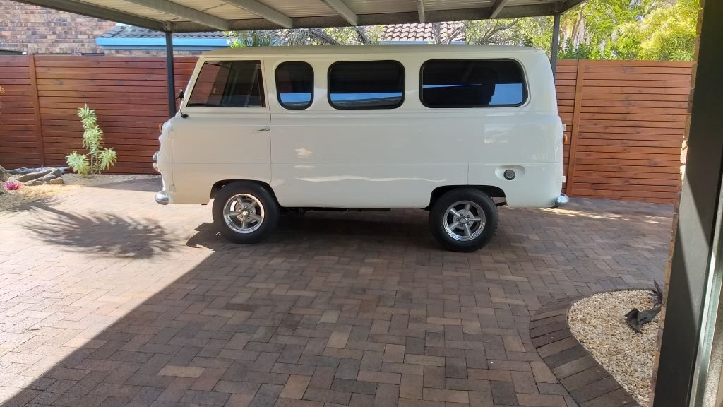
Thanks fellas, I'm pretty chuffed with the new look.
-
Mama's got some new shoes !
- 740 replies
-
- 20
-
-
And we are back on the road. New wheels must be taking the scenic route from Perth as it's been two weeks since we ordered them. Hopefully this is the last photo of the Thames with his old shoes on.
-
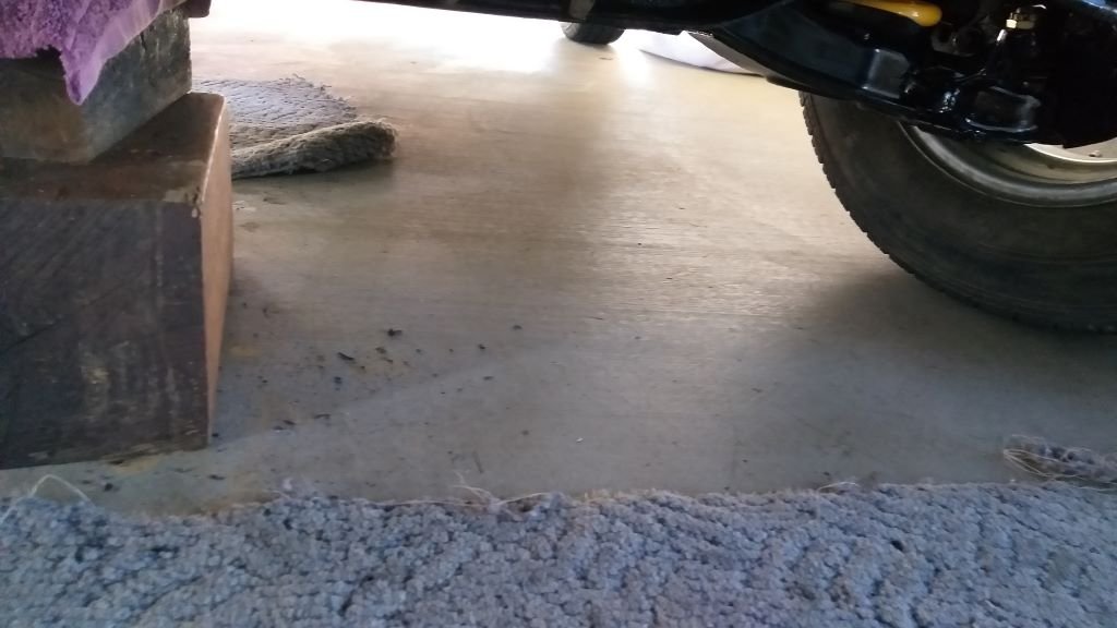
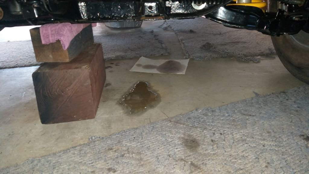
First thing this morning I slapped in my new thermostat and water neck gasket and filled the system up with sky juice. Over the course of the morning, I put the system through a series of heat cycles and so far no signs of any further leaks. It's nice to see a dry patch under the van for a change. I'll leave the water in the system for a few more days and if I'm still leak free, I'll drain and then refill with coolant.
- 740 replies
-
- 13
-
-
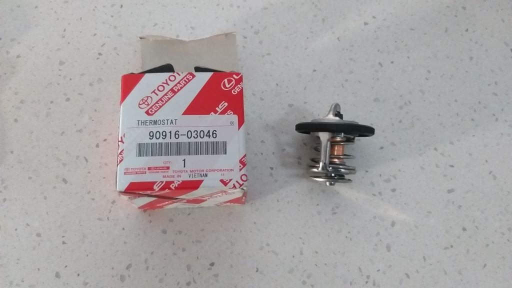
As mentioned in my last cooling system related update, my water neck seal had hardened and was really brittle so a replacement was needed, and I figured I may as well source a new thermostat while I was at it. Reading up on the Toyota van technical forum that @tortronintroduced me to there is a really good thread that talks about the thermostats used on the early HiAce vans and the fact that they are mounted horizontally rather than vertically. For this reason the writer of the article highly recommends sourcing a genuine thermostat from a Toyota dealership. I'm not totally convinced, but figured it was worth doing for extra peace of mind. Yesterday I headed into town for supplies and dropped in at my local Toyota dealership. My first visit there and I've got to say I was suitably impressed. Ordered a new thermostat and water neck seal which they sourced from Brisbane for me. Arrived overnight and the price was comparable to the stuff stocked by my local supercrap. Comparing the Toyota thermostat to the aftermarket one that was fitted to my engine, there are noticeable differences in the design, so there may well be an element of truth to the claims made on the Toyota forum. Anyway, I'll chuck them in tomorrow morning and hopefully I'm one step closer to a leak free cooling system.
- 740 replies
-
- 11
-
-
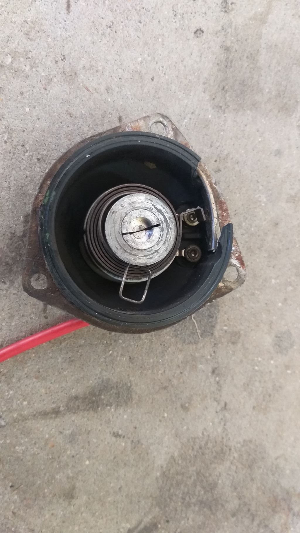
Well, I'm not exactly proud of today's hackery, but I thought I'd share it with my old school mates anyway as I guess we have all been reduced to taking short cuts at some stage. So, the long-term plan is to replace the knackered Aisin carby with either a new repro or possibly upgrading to a 32/36 Weber. I'm leaning towards the Weber as it isn't blessed with the electrically operated shut off valve and coil activated little computer control as well as the million and one emission related vacuum outlets that the Aisin has. Keep it simple I say. Anyway, I've sent an email to the Weber supplier asking them to confirm the overall height of the 32/36 together with its adapter plate as I'm headroom poor in the engine box. My existing Aisin with the factory snorkel just clears the cab floor. Fingers crossed that the Weber dimensions will work, but in the meantime I need to keep the Aisin limping along. During the start-up and initial test drive I could tell that it was running rich and I knew that this was likely due to a combination of the automatic choke and the shut off vavle that I hadn't wired up. So today I tested the choke with some temporary wiring and it's not functioning. Pulled the carby off to take a closer look at the choke and there are definite signs that it has taken a knock somewhere along the line as the choke housing has a chunk missing. No need for chokes here in the tropics and I'd rather not waste valuable time on something that is likely to be binned in the next few weeks, so I've just removed the choke coil thing for now and have cable tied the choke open. Time will tell if it's improved things or not. Easy enough just to remove the cable tie if not.
- 740 replies
-
- 13
-
-
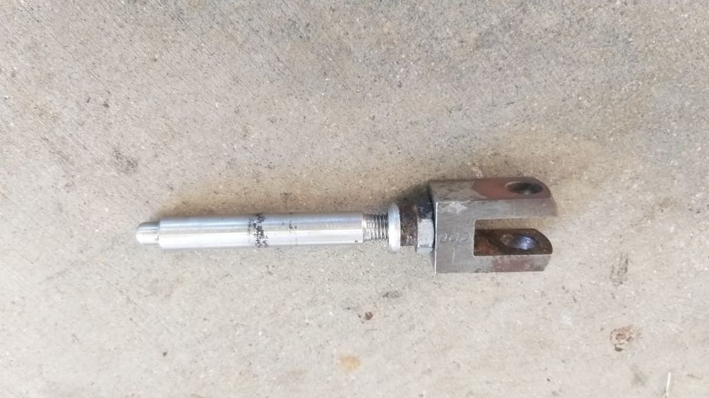
I'm going to leave the thermostat housing off until I can source a new o ring on my next trip into town, so moved on to the next snag item being the brake pedal adjustment. As previously mentioned, the brakes performed really well during my test drive, but the pedal travel was a bit more than I felt comfortable with. First thing I did was to double check the adjustment on the rear brake shoes, but they were spot on. I then pulled the master cylinder actuating rod out. It's a custom fabricated job to mate the Nissan master cylinder to the Thames brake pedal, but luckily, I got the threaded end made a bit longer than the original Thames one, so I was able to wind it out another 5mm. Slapped it back in and the pedal feels bloody good now. And that's another item ticked off the list.
- 740 replies
-
- 10
-
-
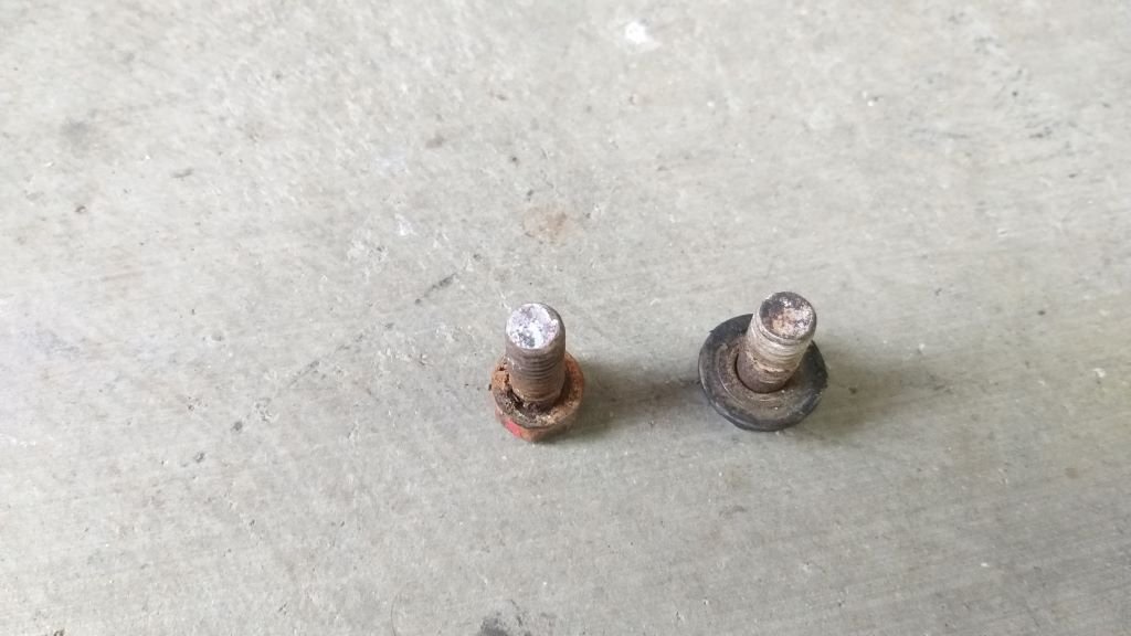
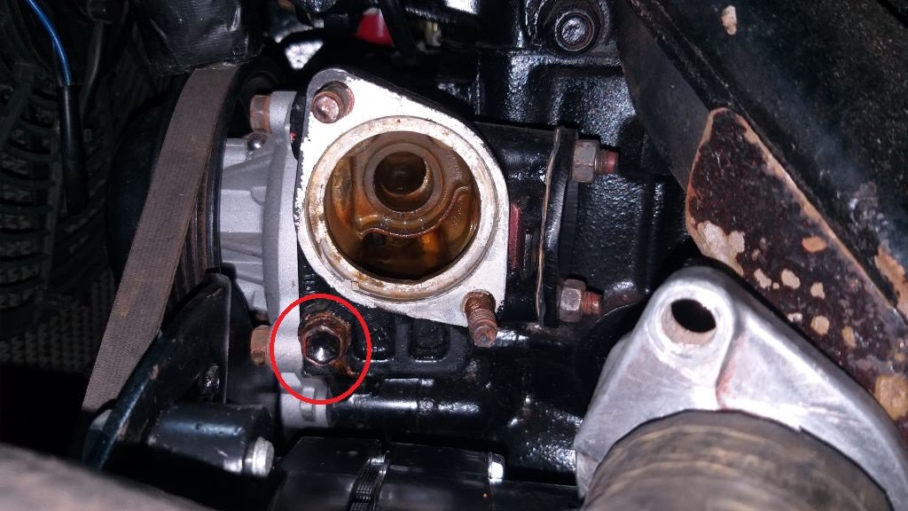
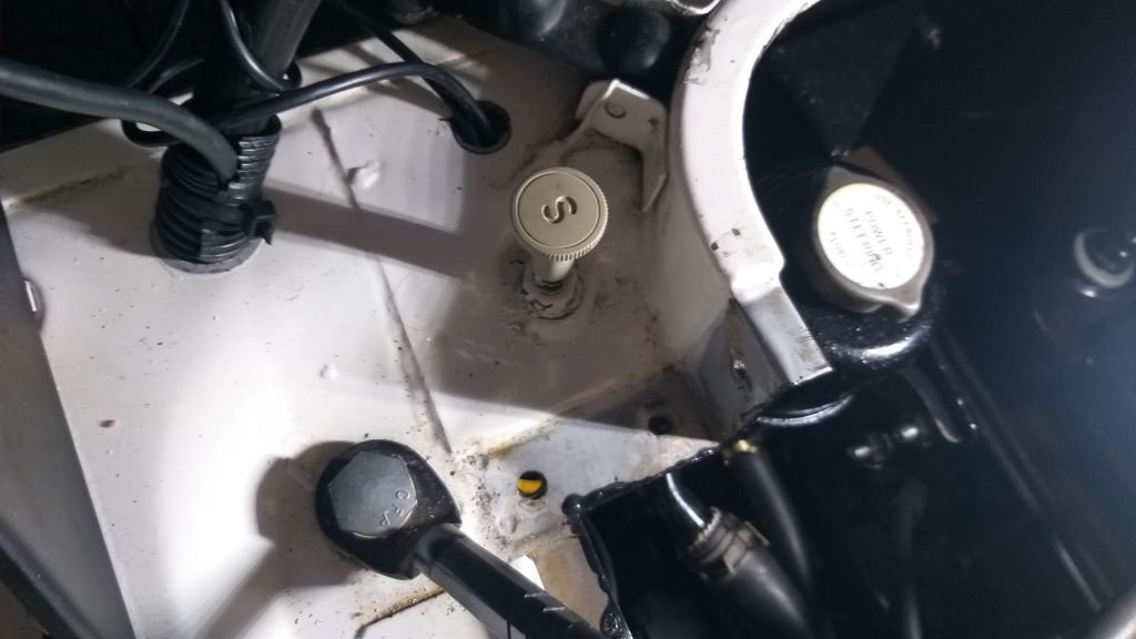
Coolant leak - Chapter 3 Well, it looks like some good "old schoolers" have come through for me again. And that's why even though I am a team of one out here in the sticks, I know that I have the support of the old school community who willingly provide valuable advice and guidance whenever needed. So, a big shout out to @tortron and @Raizer for suggesting that the rusty bolt that I highlighted in yesterday's post might well be a "wet" one and the cause of my leak. Thanks fullas! Armed with this advice I headed under the Thames once again this morning to focus on that bolt. Sure enough the thing wasn't all that tight. Pulled it out to see if I could see any signs of wetness on the threads. Not that easy to see since it has a good deal of water around it for the last week or two, but then I remembered the mock up engine languishing in a corner of the shed, so I moseyed on over and pulled the same bolt out. The spare engine has been dry for a good few years and although it's difficult to tell just by looking at the photos below, but there are definite signs that the bolt hole has been wet at some stage. So, I reckon Tori and Raizer are spot on the money. The bolt from my working engine looks a bit manky, so I'm going to replace it with the one from my spare engine. I'll chuck a bit of thread tape on it just for a bit of added insurance. I was intrigued by the photo in Tori's post which led me to the Toyota van tech forum - something that up to now I didn't know existed. Checked out a few thermostat related posts on that site and it turns out that the housing doesn't use a conventional gasket, but rather a rubber o ring type gasket that fits around the edge of the thermostat. Might pay me to see if I can source a new gasket next time I am in town.
-
Thanks for the suggestion @torton and @Raizer I'll check it out.
-
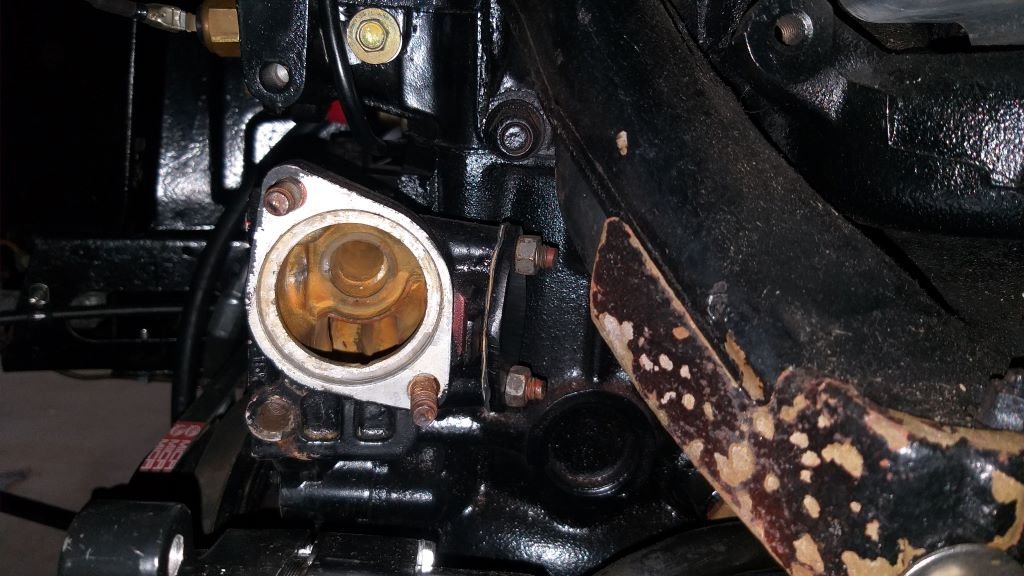
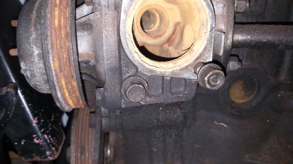
Coolant leak - Chapter 2 After fitting the new Mini ignition switch, I fired up the old Thames and let it idle for a few minutes. Tidied away a few tools and then took a peek under the van and lo and behold I was greeted with a steadily growing puddle of water. Bugger. Grovelled around under the van and although it's not that easy to see past the alternator, I now suspect that the source of the drip is the thermostat housing itself, so I've pulled that off. With the alternator swung out of the way and peeking into the engine box from the wheel arch I can see definite signs of rust on the head of the bolt below the housing so I'm taking that as evidence that I'm on the right track. Even although the existing gasket is new, I fitted it dry, so tomorrow I'll make up a new gasket and will add some sealant this time around. Stay tuned for the next exciting episode.
-
Coolant leak - Chapter 1 I've been working on the coolant leak in tandem with my wiring efforts. I was getting a steady drip running down the left-hand side front corner of the engine. My first thought was that it might be coming from the joint where the lower radiator hose meets the trimmed down thermostat neck. The thermostat neck is cone shaped and the hose is rather stubby so I figured that I may have positioned the clamp too far up the hose. As a "proof of concept" I chucked a second hose clamp on further down the neck, filled the system with water and placed a bit of kitchen paper under the joint. Let is sit for 48 hours and not one drop. Thought I'd solved it.
-
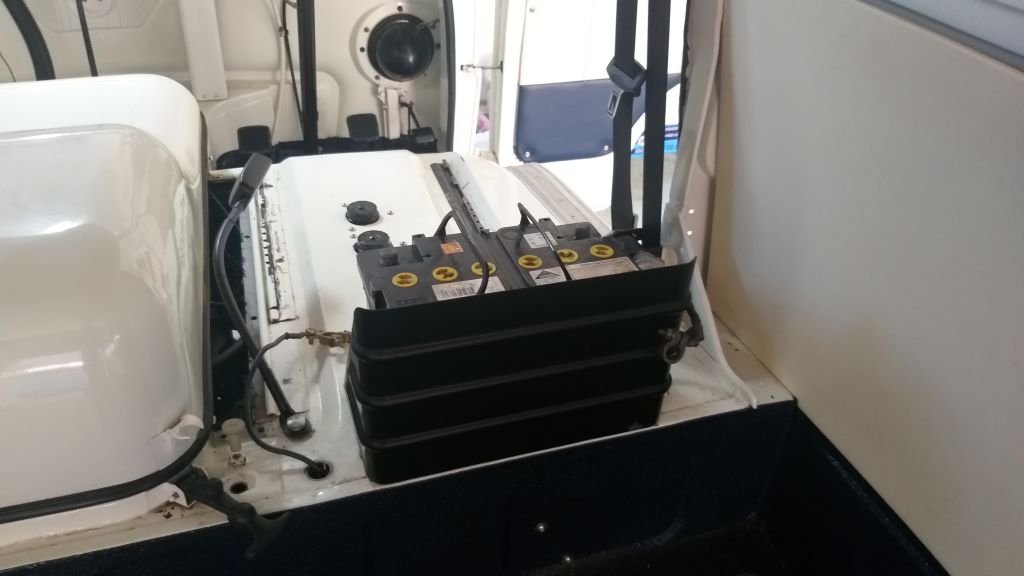
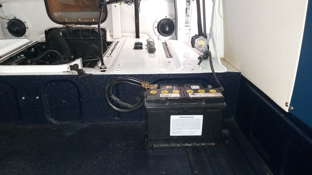
Electrical gremlins - Chapter 2 Whilst I am extending wiring to replace the starter button with a conventional ignition switch, I figured I may as well relocate the battery at the same time. Sometime in the future I plan to build a rock 'n' roll bed just behind the front seats. It will have a little padded shelf facing the front of the van for our wee dug and a rear facing sofa type seat so we can enjoy roadside smokos in relative comfort. The base of the sofa will double as a storage box running the width of the van and will be a handy place for the jack, wheel brace and emergency tool roll as well as space for a house battery. The sofa and dog box will fold down to create a queen size bed for lush overnighters. It's kinda all planned out in my head at the moment. Anyway, the factory battery position behind the driver's seat will clash with this plan, so I decided to drop it down onto the rear cargo floor so that it will also live in the storage box once this is built. Drilled a few holes for the battery leads, chucked in a few rubber grommets and its basically done. I'll work out what I'm going to do from a battery hold down perspective as part of the storage box build.
-
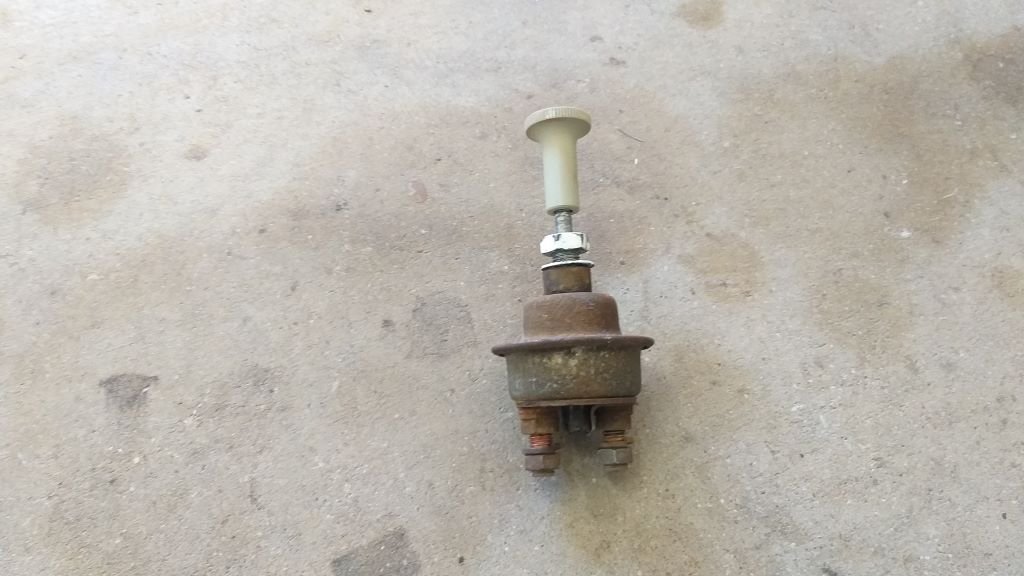
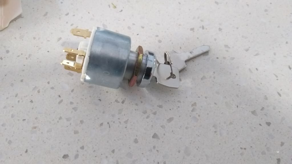
Electrical gremlins - Chapter 1 Next items on the snag list to address are a few electrical issues. Now I've never been a fan of the factory fitted starter button. For one thing it's tucked away in an awkward place and I keep forgetting to turn the key on before hitting the button. Doh So, in a way I'm glad that the thing is stuffed as it forces me to make a change. I previously mentioned that I was planning to replace the key switch with a proper ignition switch from a Mini MK2. The new switch arrived earlier this week, so I thought I'd get it fitted today. Started off by pulling out the offending starter button. Ford in their wisdom have used one of the terminals on the switch as a common point for the main power feed with a loop wire up to the positive terminal on the battery. This means that I need to extend the main wire to reach the battery as well as extending the thicker wire that runs to the starter motor. Rummaged around the wiring left over from my donor vans and found a long enough heavy gauge wire for the starter motor. Winner. That's now cleaned up and fitted. Tomorrow I'll break out the old soldering iron and extend the rest of the wires. Thanks for reading.
-
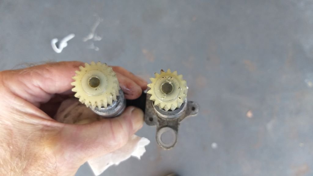
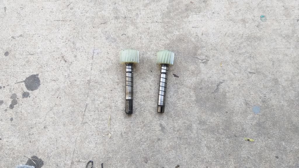
Had a few minutes spare yesterday so thought I'd best fill the gearbox with oil before I forget. Remembered that I needed to fit the little speedo drive while I was under the van. And that is where the fun began. Pushed and shoved and fiddled about but the little speedo drive just wouldn't slip into the hole. Headed over to the original gearbox that is languishing in the naughty corner and the drive slipped straight in. WTF. Back under the Thames with a little lube but still no luck. Eventually pulled off the inner shaft with the attached nylon gear and then offered the housing up to the hole. Slipped in perfectly. And it's at that point that I started to smell a bit of a rat. So, after lunch with the speedo drive in hand I headed over to Grant's place and grovelled around in the back of his HiAce where I had stashed the 1RZ bellhousing, clutch fork and electronic speedo drive that I had removed during the big swap over. And ... bugger me, the nylon gear on the electronic drive is way smaller. Pulled the little circlips that hold the shafts into each housing and sat the two side by side. Shaft on the electronic drive is shorter. Back home I chucked the shorter electronic shaft into the housing and offered up my speedo cable. Luckily the cable still engages even although the shaft is shorter. Offered the drive up to the gearbox and it slipped in like a charm. Not sure what the smaller gear is going to do in terms of speedo accuracy, but I'm probably going to need one of those calibration boxes to match the Thames speedo to the gearbox anyway, so it's not a big deal.
-
Well, looks like I have solved the brake fluid leak. No drips in the past 24 hours. Gave the brakes a few good pushes this morning and it's still dry as a bone, so I'll tick that of the snag list.
-
Brake fluid leak - Chapter 3 With the reservoir outlet ruled out as the cause of the leak, I turned my attention to the joints on the adapter and the barbed fitting. There is no pressure at this point in the system, so it's just a case of the fluid leaking under gravity. Bizarre I know, but there you go. Checked out the mating surfaces on each of the joints and they all look to match and are in brand new condition. I'm using PTFE pipe to feed the master cylinder, so I'm assuming that PTFE pipe tape would be brake fluid friendly as well. So chucked a bit of tape on each of the threads and gave the joints a good cranking. I've put everything back together and filled up the reservoir. I've placed another piece of kitchen paper under the joints and will leave things as is for the next 24 hours. Fingers crossed that I've solved the leak. Thanks for reading.
-
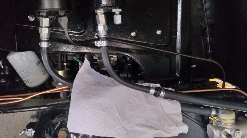
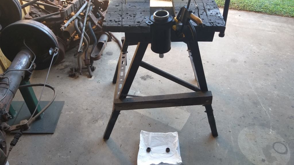
Brake fluid leak - Chapter 2 In terms of the source of the leak there are three possibilities: Firstly, the outlet nipple is crimped into the bottom of the reservoir with a little washer providing a seal. These washers have been known to fail if allowed to dry out. The next possibility is a leak from the adapter that goes between the outlet nipple and the barbed fitting that takes the hose. The third possibility is a leak on the barbed fitting where it screws into the adapter. I've ruled out the leak being on the rubber hose joint for now. Looking at the image in my previous posting you will notice that the reservoir has two outlets, one of which has been blanked off. The reason for this is that in factory mode with a single circuit brake setup the reservoir services both the brake circuit as well as the hydraulic clutch. Since I'm using two reservoirs on my dual circuit brake set-up, I'm feeding the rear brake circuit and clutch off the other reservoir and have just blanked off the clutch outlet on this one. To rule out the issue being with the crimped nipple I removed the reservoir from the van and clamped it to my dodgy work bench. I then moved the blanking off fitting from the clutch outlet to the brake outlet and then filled up the brake portion of the reservoir with brake fluid. Put a bit of kitchen paper under the reservoir to make it easier for my poor old eyes to spot any drips. Left everything for 24 hours. Checked it this morning and no leaks from the outlet. Phew, that is a relief.
-
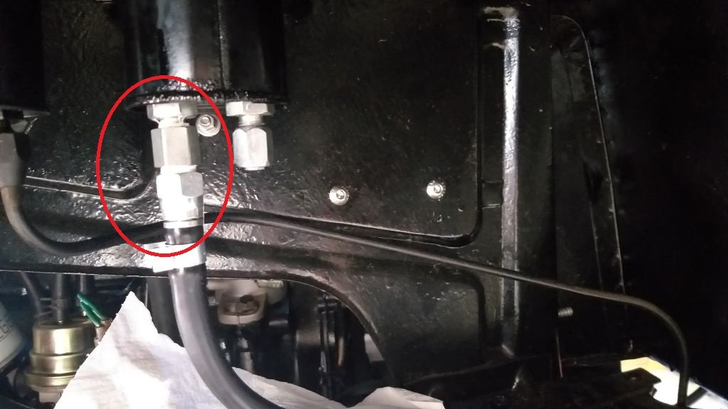
Brake fluid leak - Chapter 1 I'm steadily working my way through the post drive snag list. With the gearbox and tyre rubbing issues hopefully behind me, the next priority item on the list is resolving the leak on the brake fluid reservoir that feeds the front brake circuit. Having a good look at the reservoir the fluid seems to be seeping from somewhere on the joint circled in red in the photo below:
-
Thanks for the link to your build @Tiger Tamer I'll have a good nosey.