


sr2
-
Posts
764 -
Joined
-
Last visited
-
Days Won
1
Posts posted by sr2
-
-
3 hours ago, Lord Gruntfuttock said:
A shunt resistor will let you run the 20A ammeter, just be aware of parasitic load if it's connected all the time?
Will depend on value of shunt resistor, only 12V pushing it so anything over 1kohms total resistance (including parallel meter resistance) means you're looking at milliamps...https://www.rohm.com/electronics-basics/resistors/shunt-resistors
Please correct me if I'm wrong but I thought you used voltage drop across a shunt resistor to calculate the amps? (i.e. I'd need to use a volt meter).
-
5 hours ago, Flash said:
You did a top job on the gauges Simon and the ignition switch is an absolute work of art. You just can't beat that vintage look.
Quick question for you regarding the Nissan wiper motor that you used. Do you know what model Nissan it came out of? I played around with a few options for the Thames, but I'm not that happy with my current setup so I'm thinking of doing a rework and your setup looks ideal.
Hi mate, the wiper motor was off a Nissan Tilda C11 (2004 to 2011 I think?).
-
 1
1
-
-
- Popular Post
- Popular Post
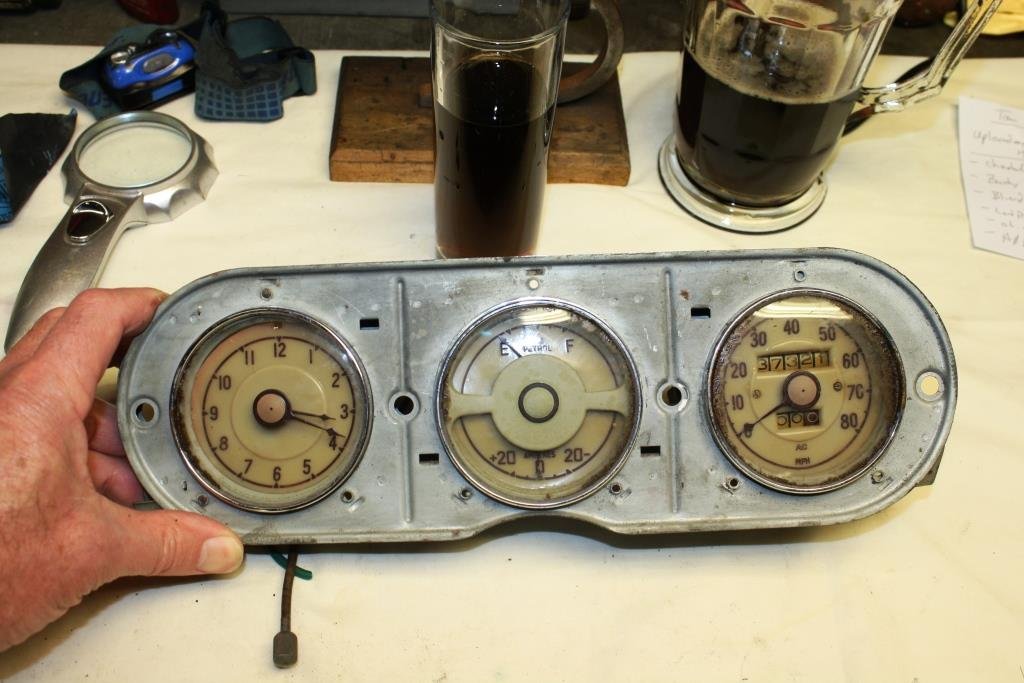
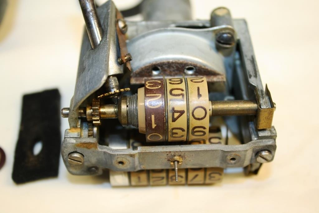
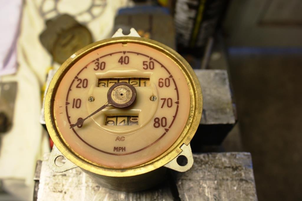
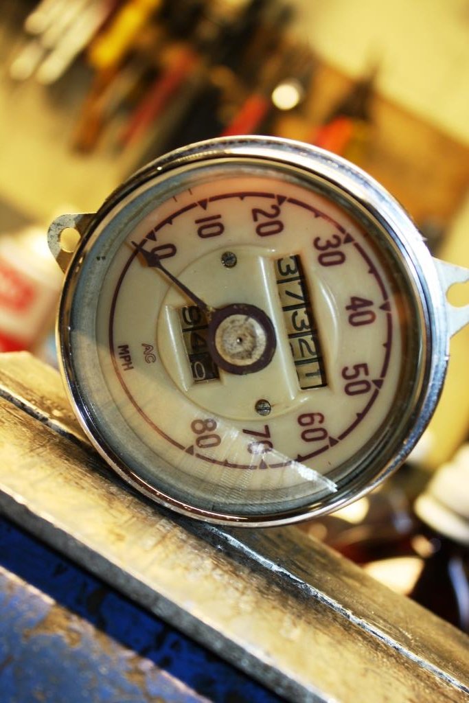
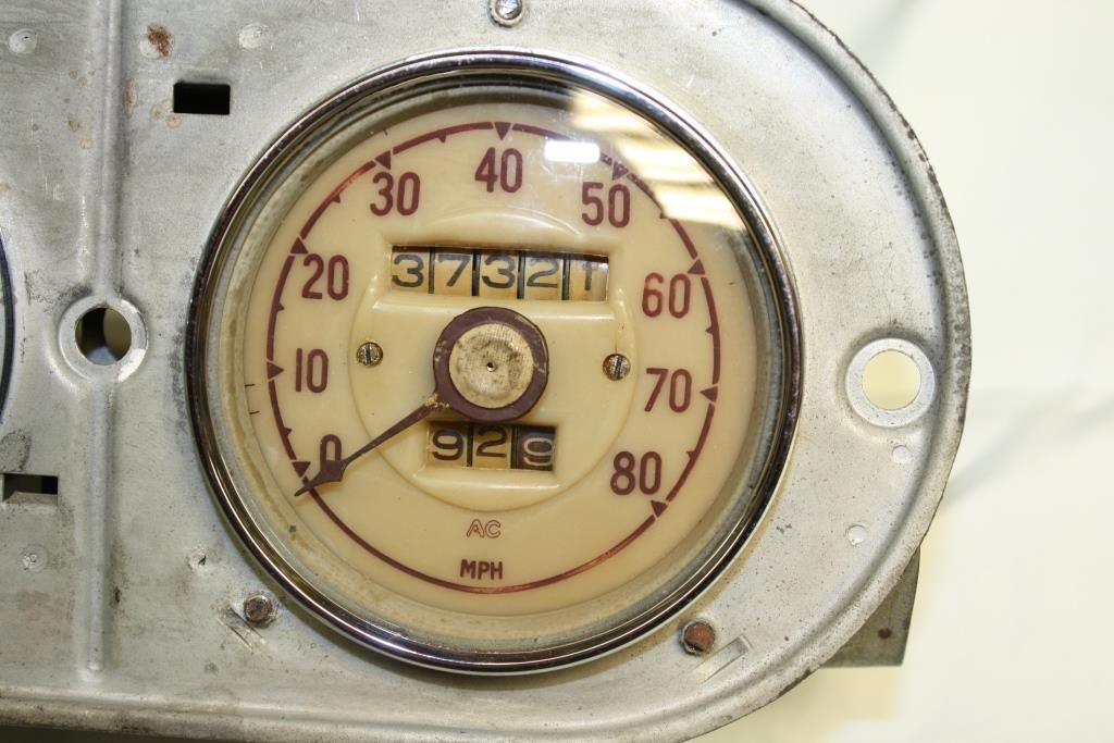
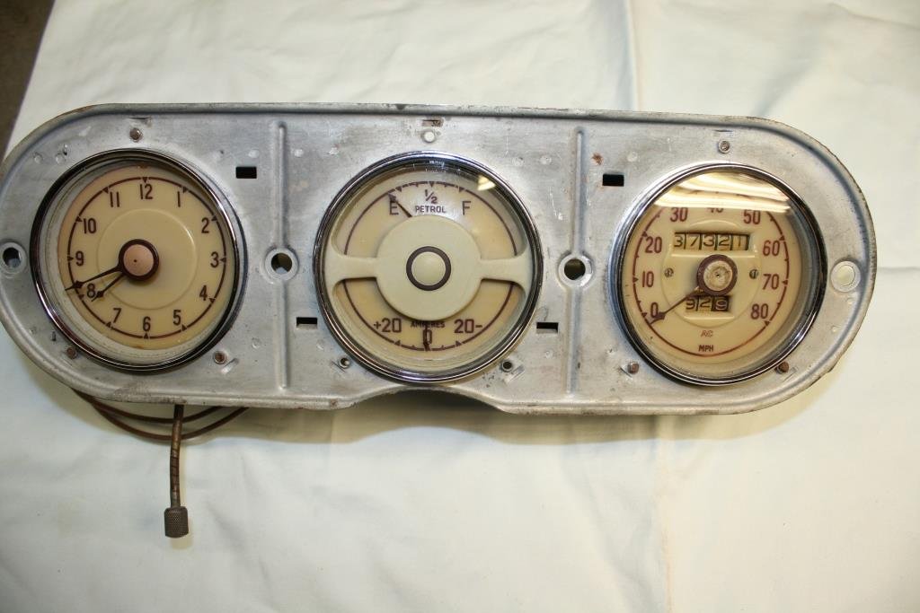
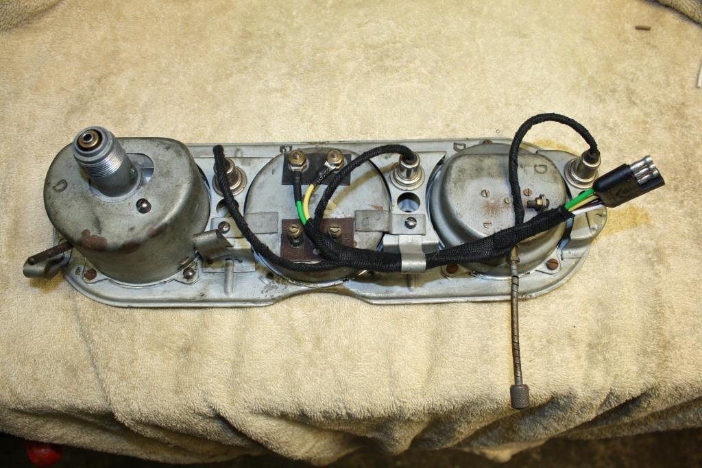
Time to have a go at the dash cluster. I’ve got a spare one and with some luck should be able to make a good one out of the pair.

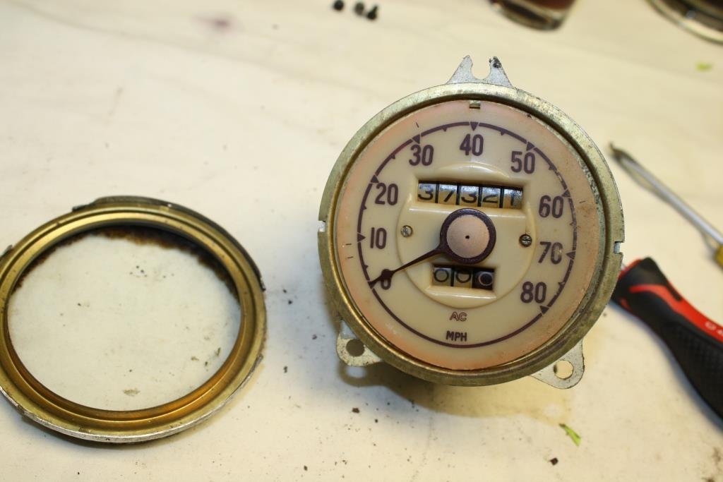
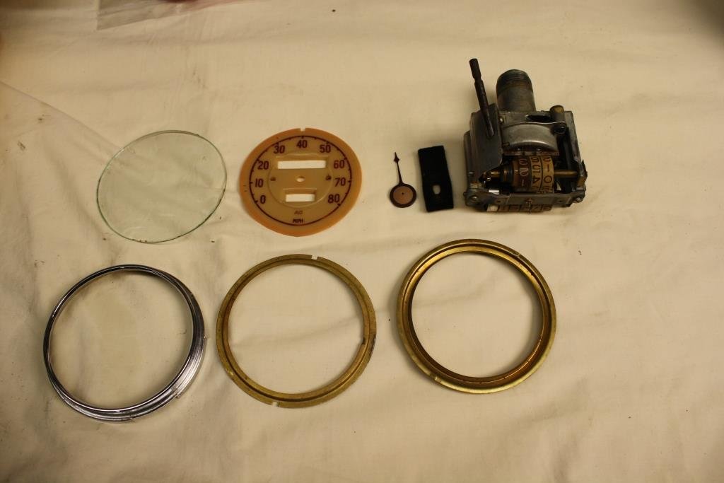
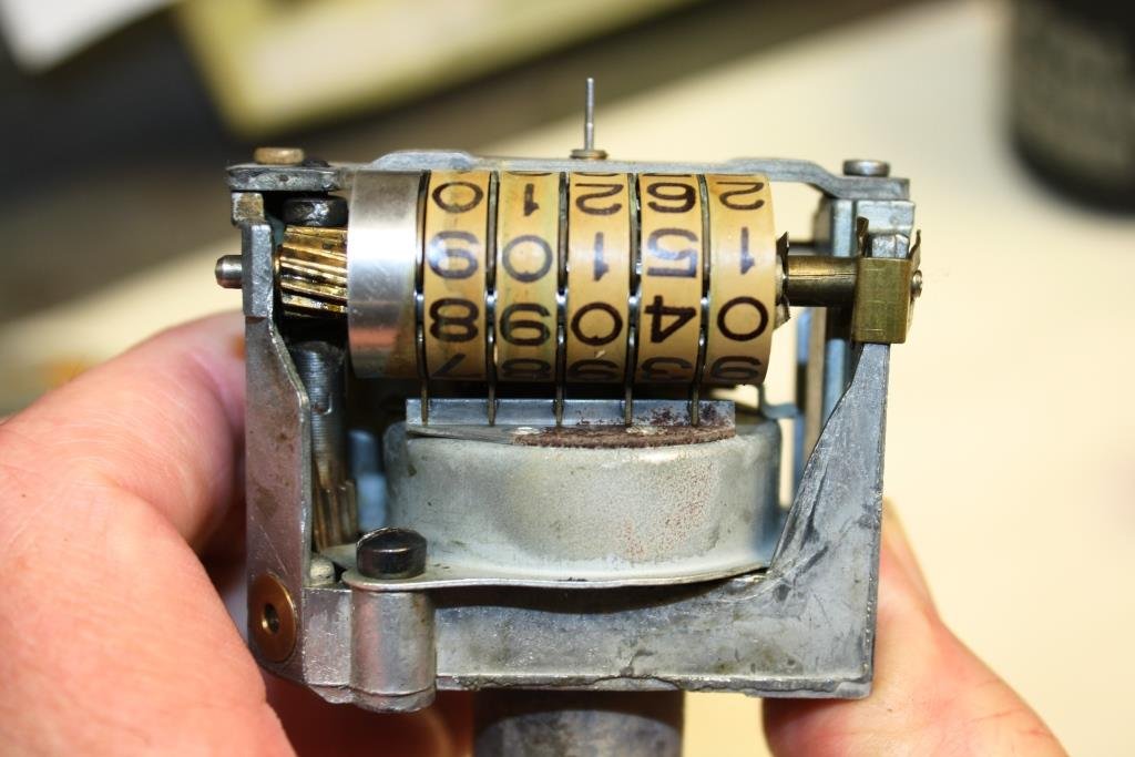
The speedo came apart easily
All I did was to carefully clean the mechanism and add some light oil….
Assembled it all carefully……
…. tested it with a drill….. and the bloody thing worked!
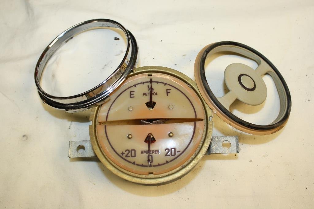
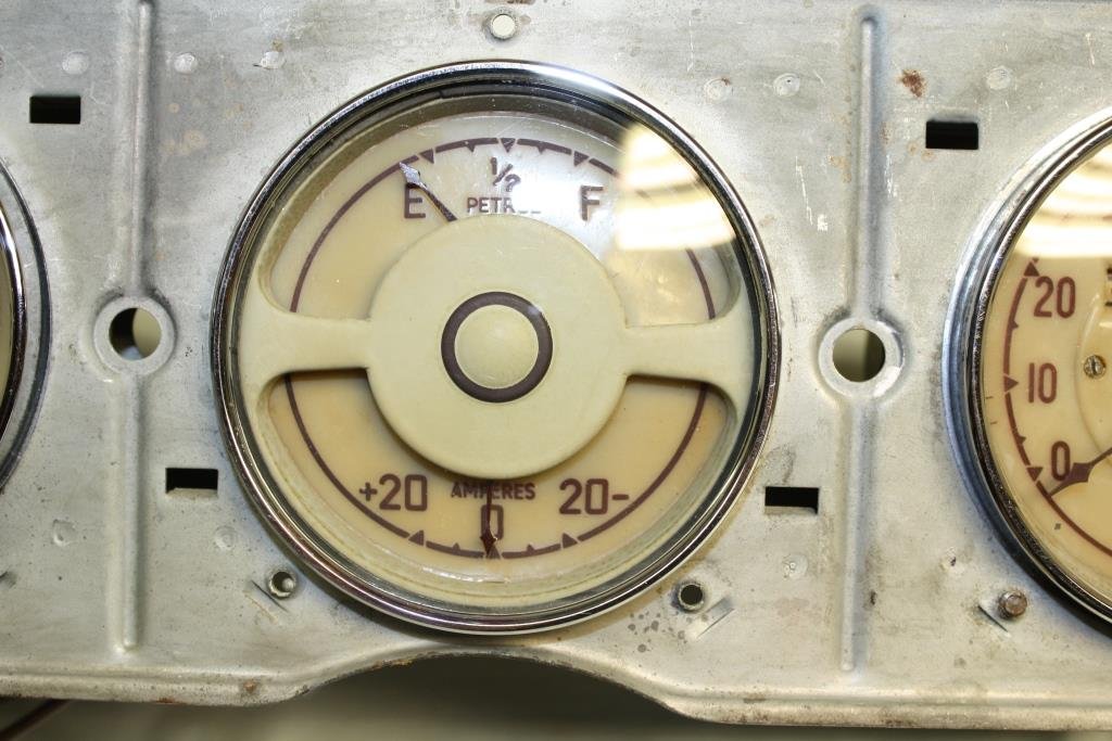
I knew there was still life in the fuel gauge so I just stripped, cleaned and reassembled.
I’m not sure what you do with a 20 amp meter when you’re running a 60 amp alternator…….I’m open to suggestions?
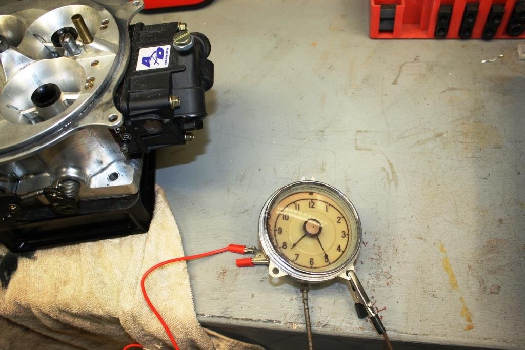
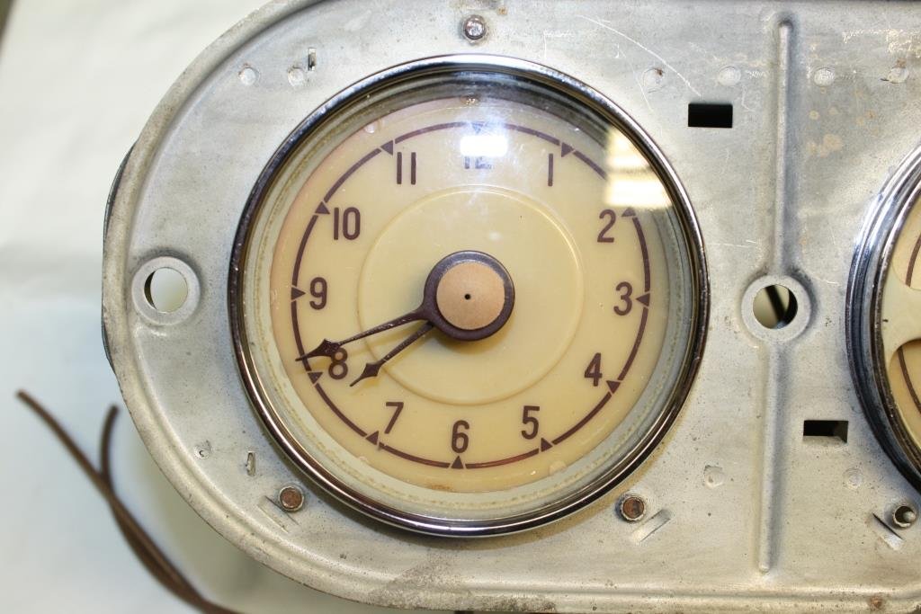
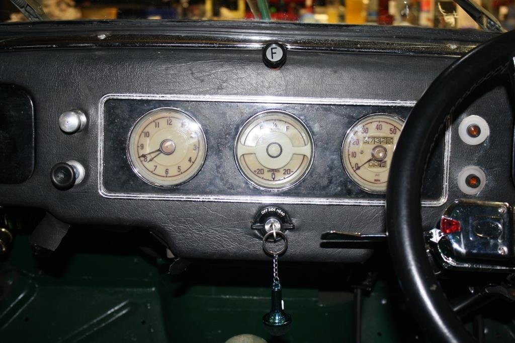
Amazingly the clock works; problem is its positive earth.
So I made the call that for the time being I’m happy with it being accurate only twice a day and just gave it a good clean.
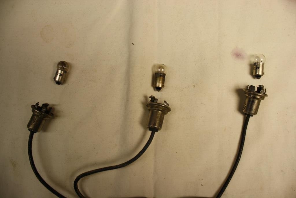
I managed to source the right bulbs for the backlighting but the sockets needed rewiring.
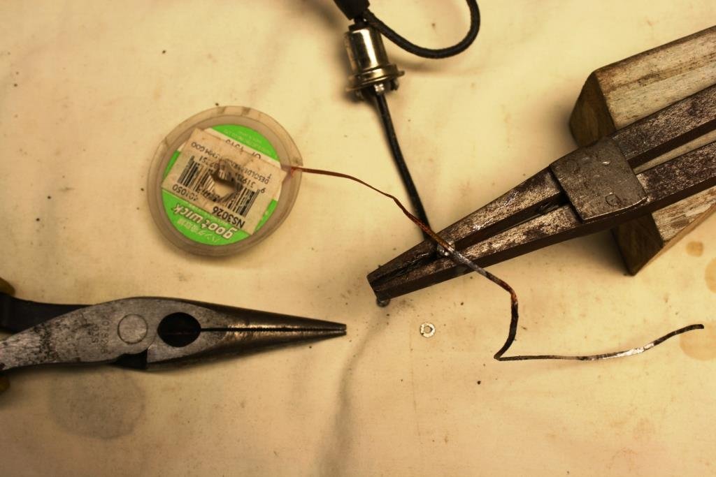
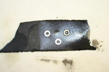
Managed to de-solder the tiny contact washers…..
Soldered them on to some new wire and assembled them with the old springs underneath.
Wired it all up for plug ‘n play.
Finally back in the dash, looking good above the ignition/light switch.
-
21
-
- Popular Post
- Popular Post
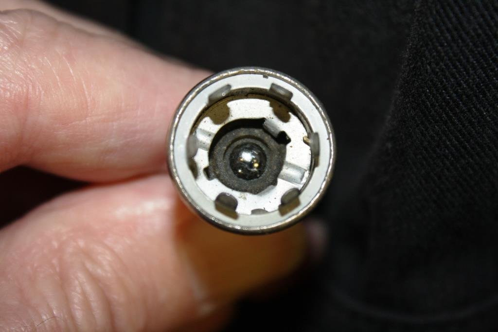
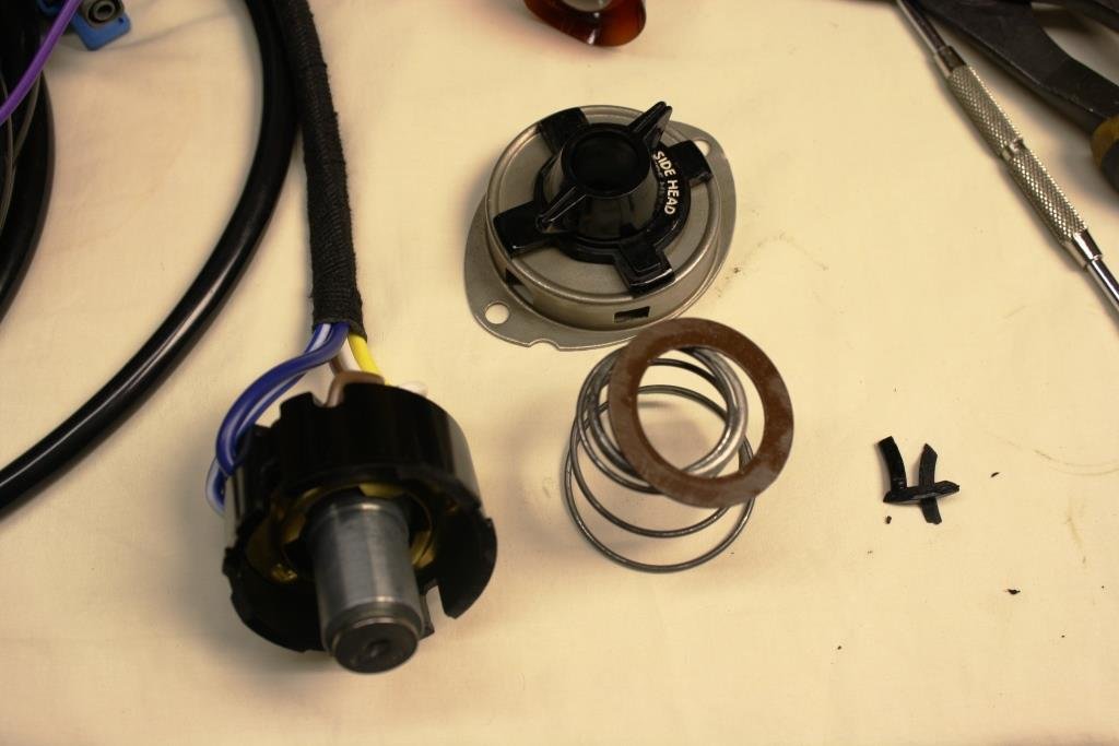
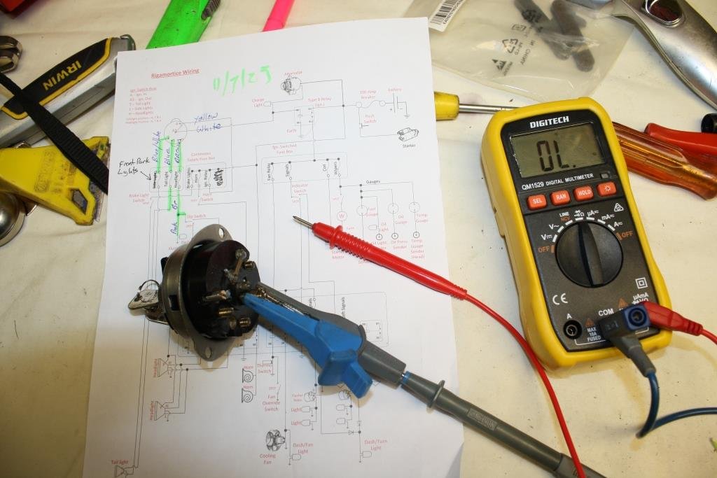
I was bench testing Rigamortice’s flash new wiring loom while admiring the cool ignition/headlight switch…..
….everything was looking good when the entire switch assembly blew into pieces in front of me.
The locking tabs on the Bakelite body had disintegrated allowing the spring to do one very quick disassembly job!
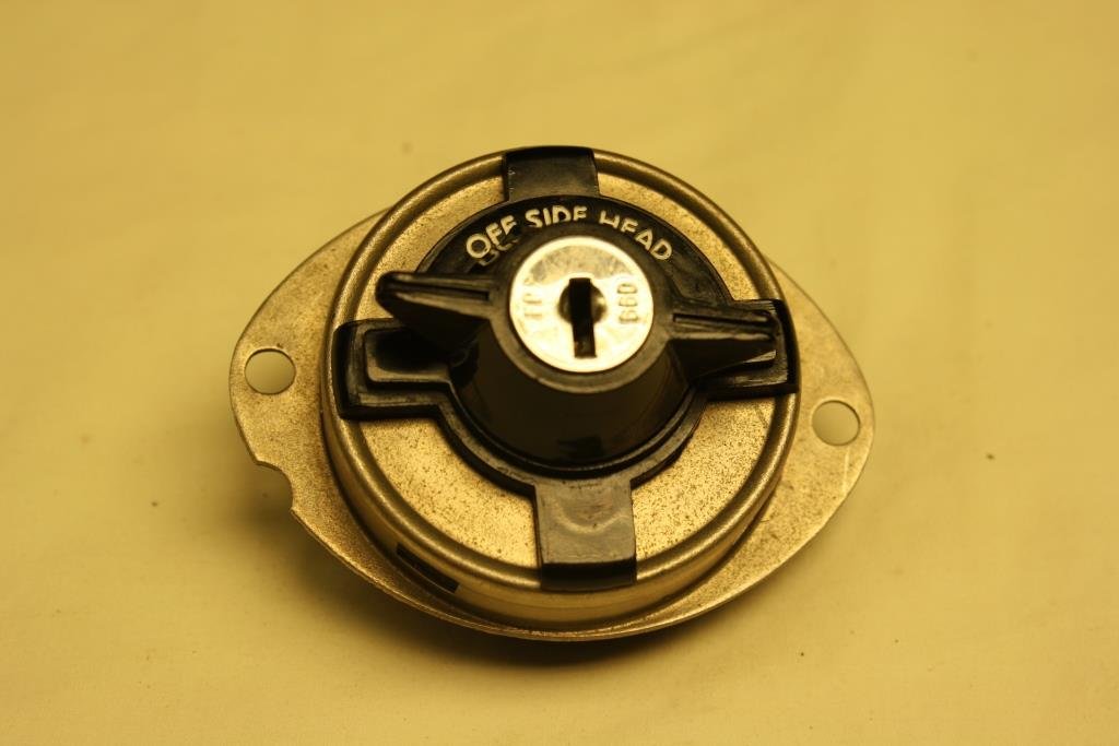
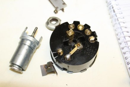
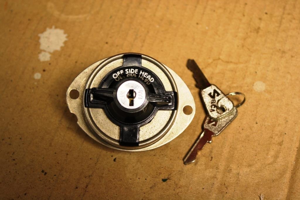
I had a big hunt through my spares and found I had another one.
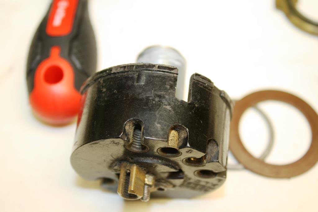
The front was a mess but the main body looked in much better shape. (Sometimes you get lucky).
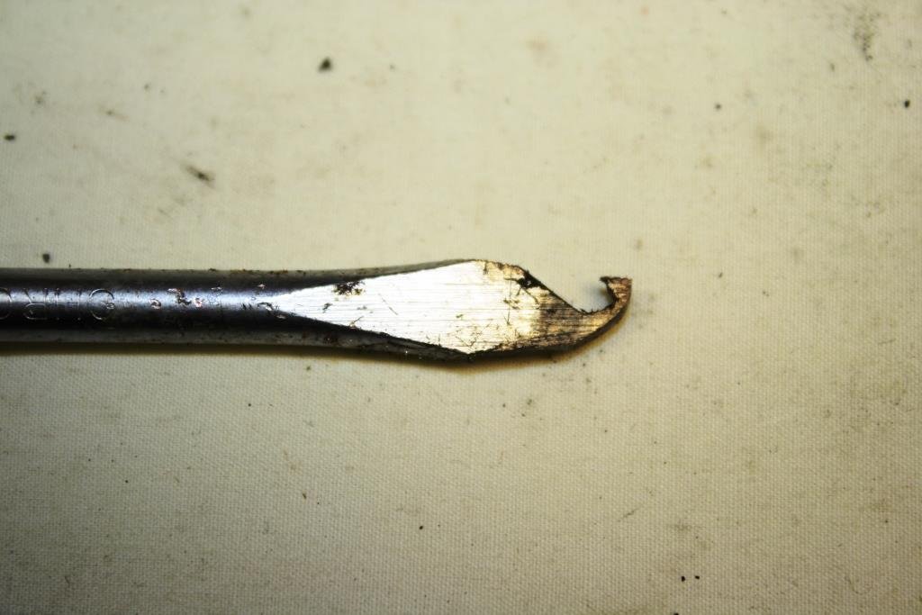
I had to sacrifice an old screwdriver to make an assembly tool.
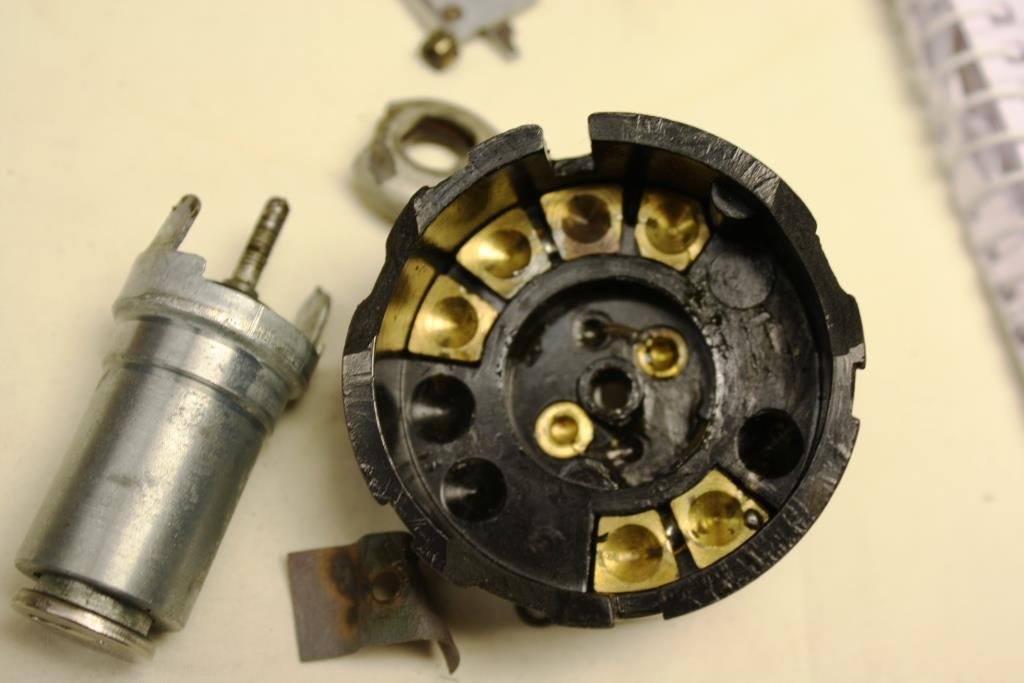
Everything cleaned up well…..
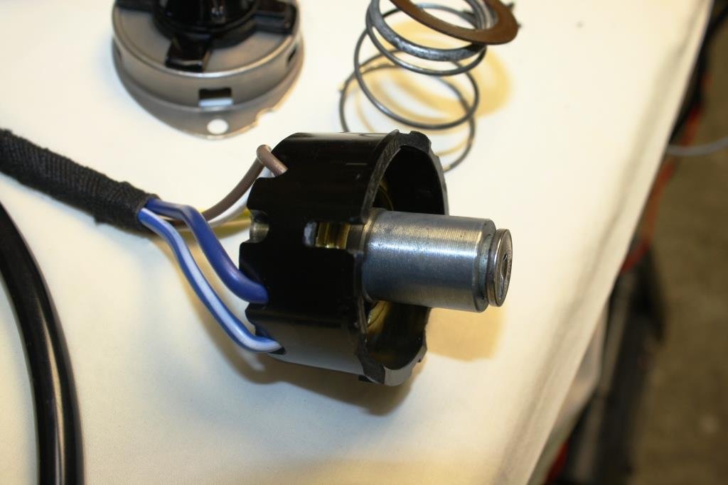
And I managed to fit the original ignition barrel.
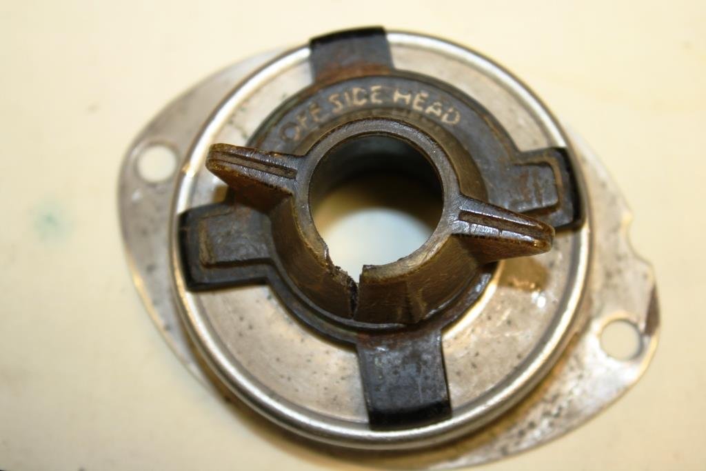
The assembly procedure obviously required six hands …….when I got it wrong the spring blew pieces all over the esteemed sr2 man-cave!
Three attempts later I finally managed the job with only two hands, gaff tape, copious shots of Wild Turkey, some nasty horrible expletives, and old-school perseverance.
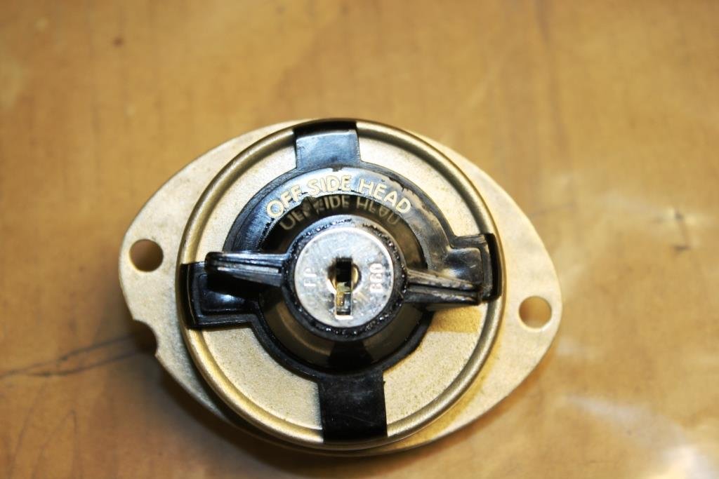
And it even tested OK
-
24
-
- Popular Post
- Popular Post
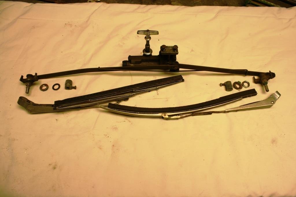
I’m at the stage where I need to make a call on the windscreen wiper setup as there is limited room under the dash and the wiring loom needs to clear the moving parts..
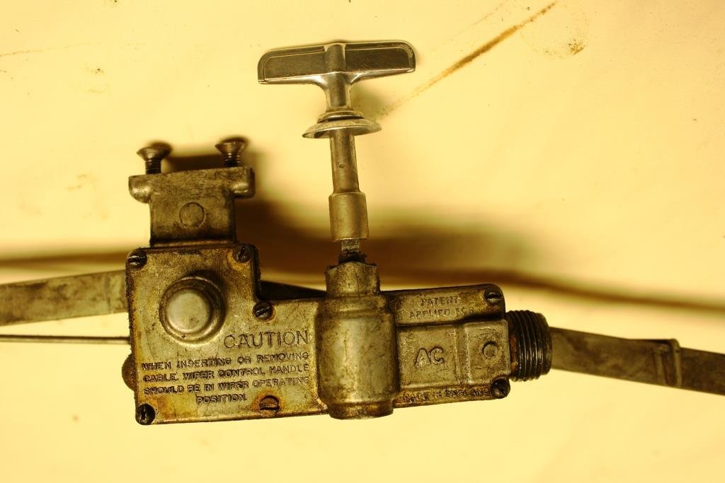
The original pre-war system was driven by a Bowden cable that believe it or not was in turn driven from the camshaft. If you think the old vacuum wipers were crazy, matching engine rpm to wiper speed added a whole new dimension to driving in the rain!
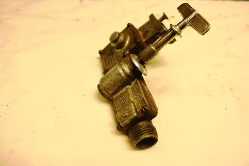
It had a cool little AC Delco gearbox with a clutch.
I toyed briefly with the idea of powering up the Bowden cable with a small electric motor but due to the overall condition of the system I made the call to start from scratch.
I’d done an electric conversion in the early 80’s but it was pretty rough (to say the least) and the “Lucas prince of darkness” wiper motor was locked up solid.
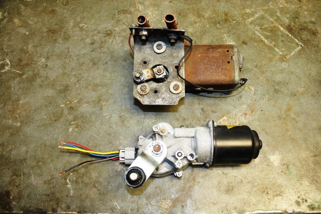
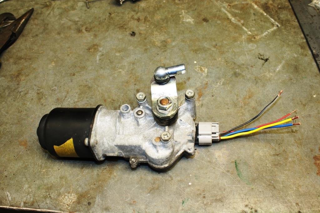
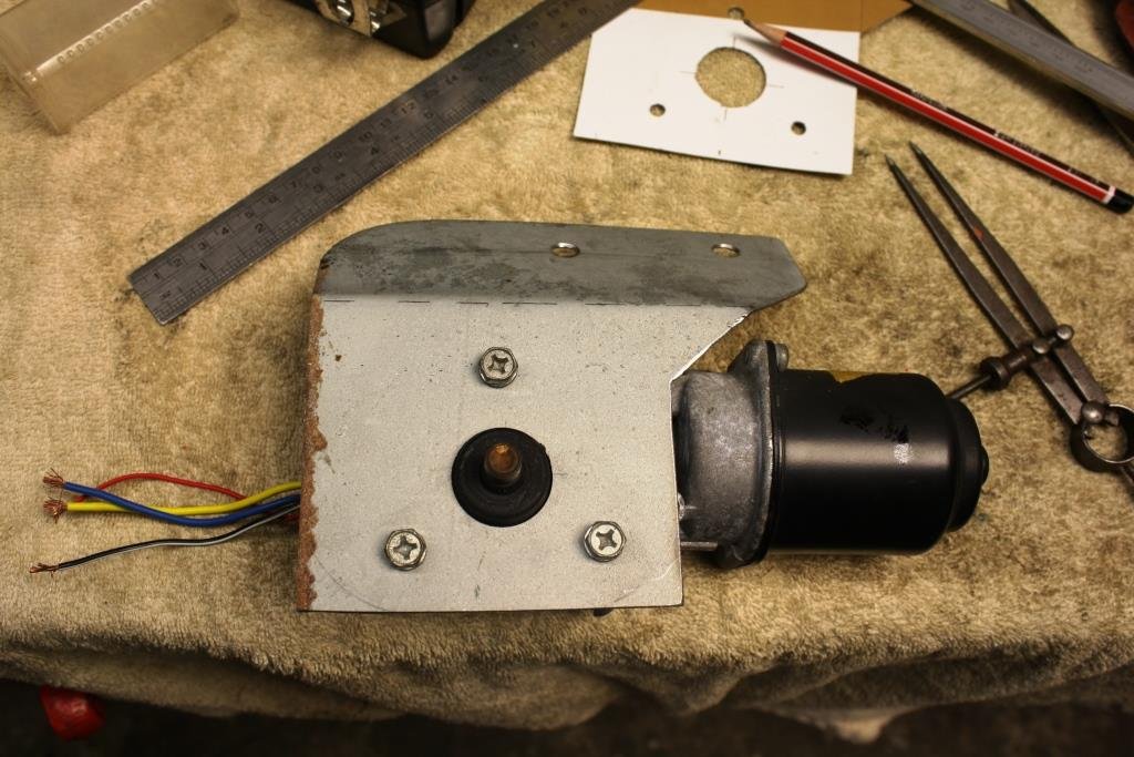
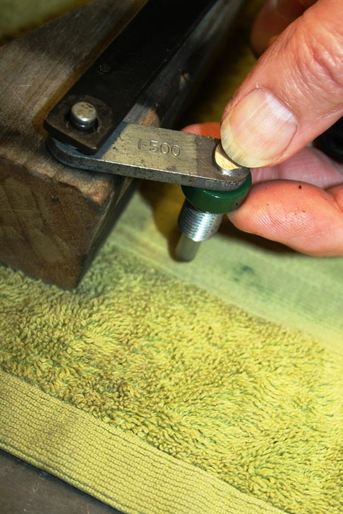
I found a Nissan rear window wiper motor that was small and compact…….
Old vs new…….
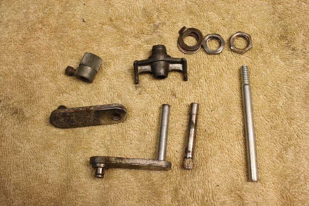
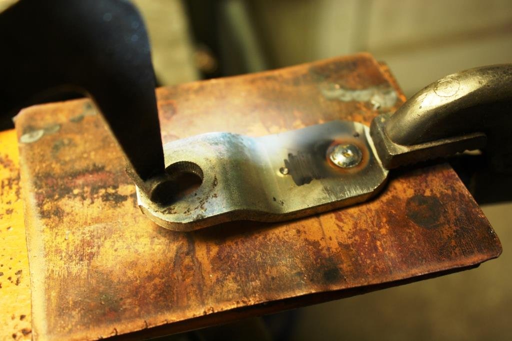
I modified the output arm to take an 8mm rose joint.
\
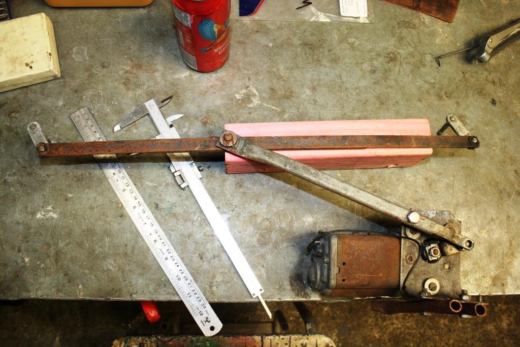
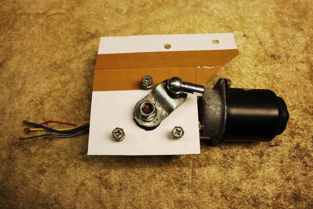
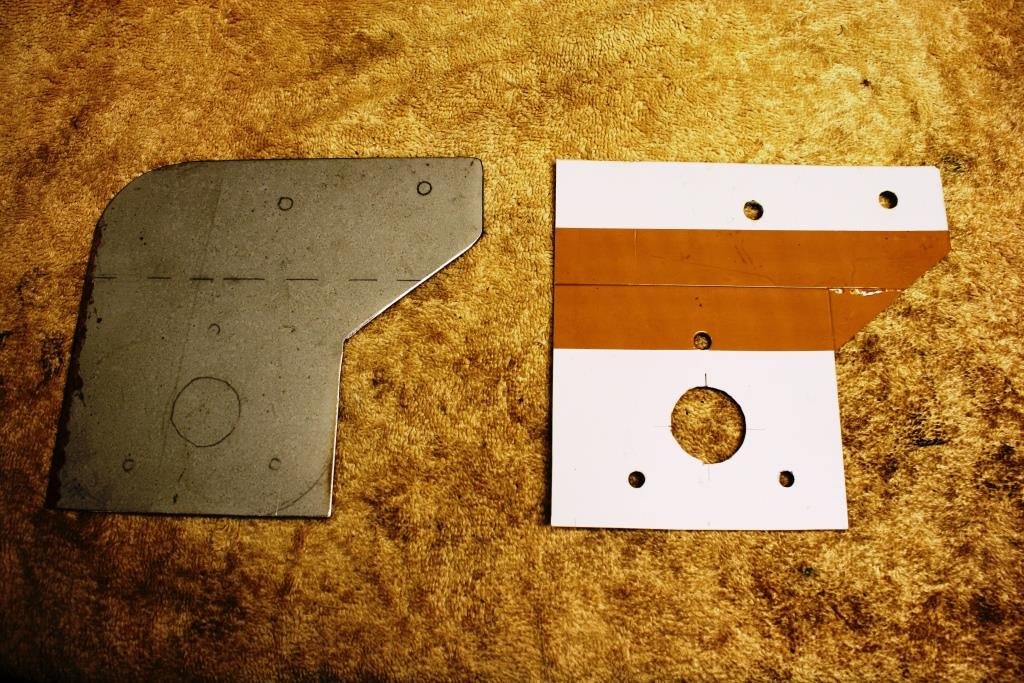
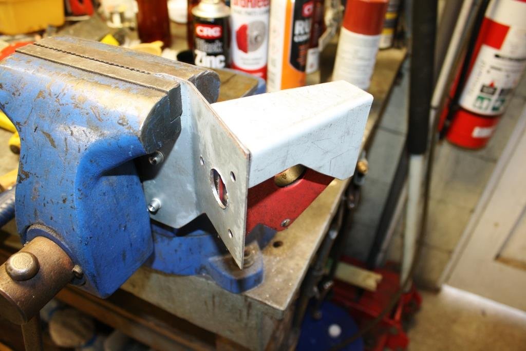
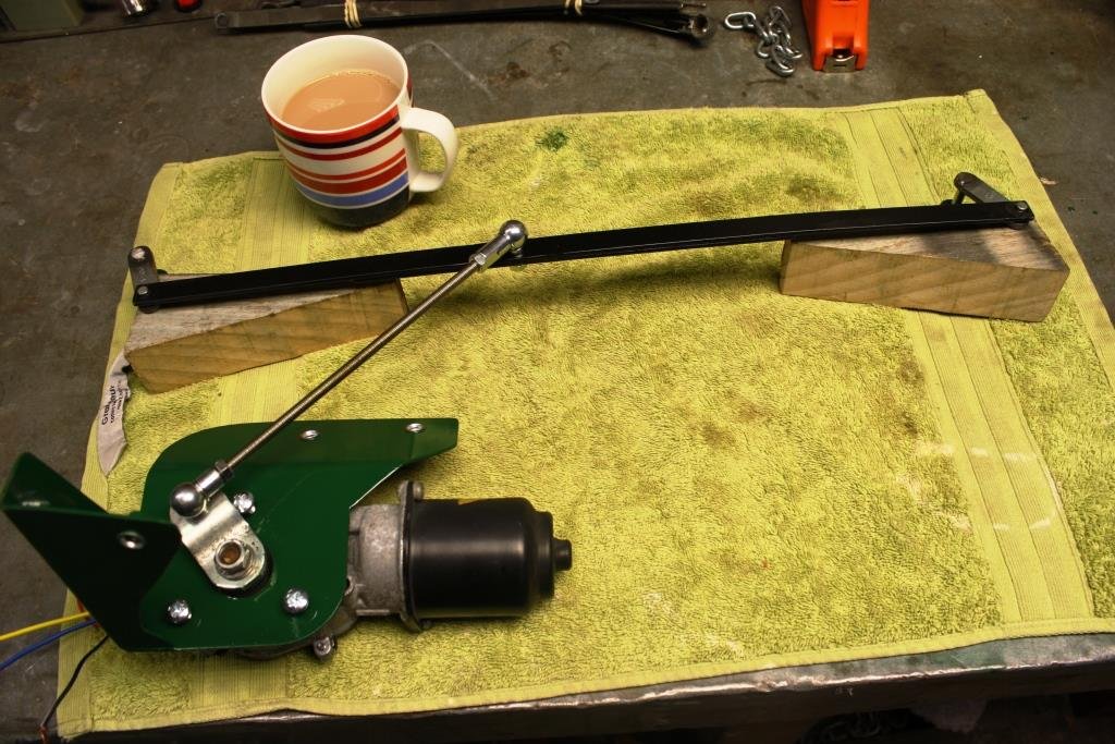
And once again fired up the CAD…
Some bending and welding…..
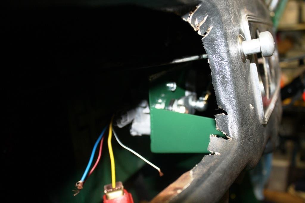
….and it tucks under the dash well out of the way of the instrument cluster.
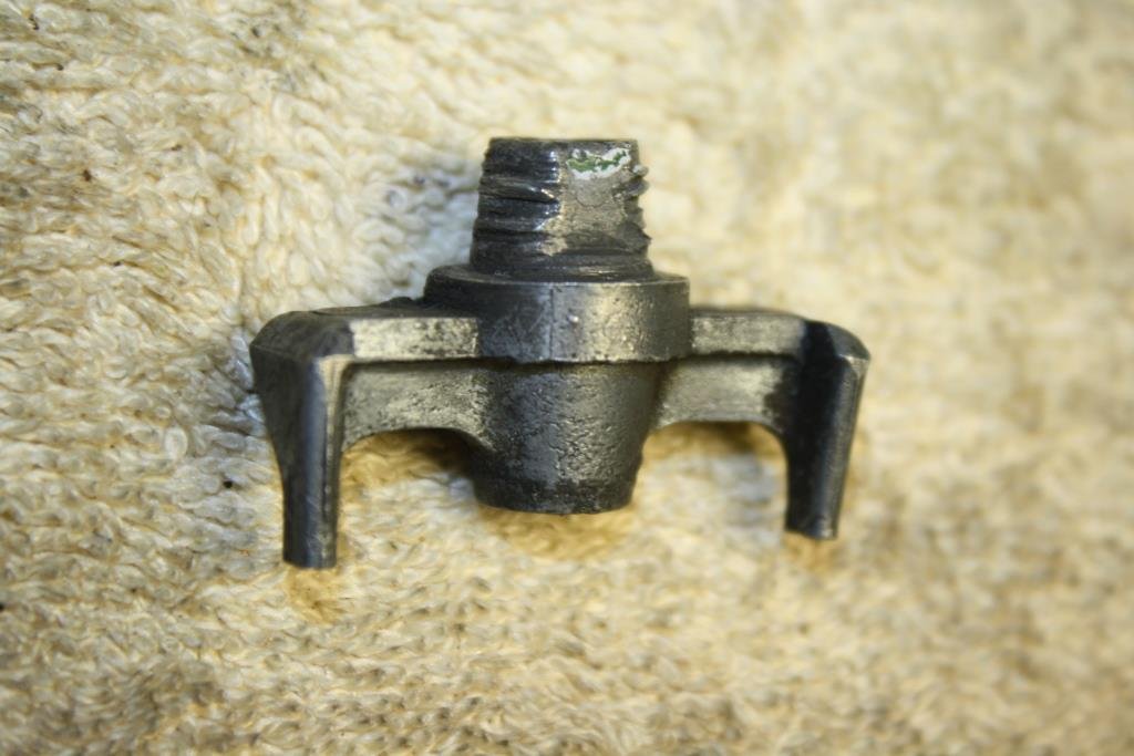
The alloy wiper pivots were badly corroded…….
So I made up some new ones
Some more “insipid green” paint……….
A bit of mucking around to get the ratio’s right………
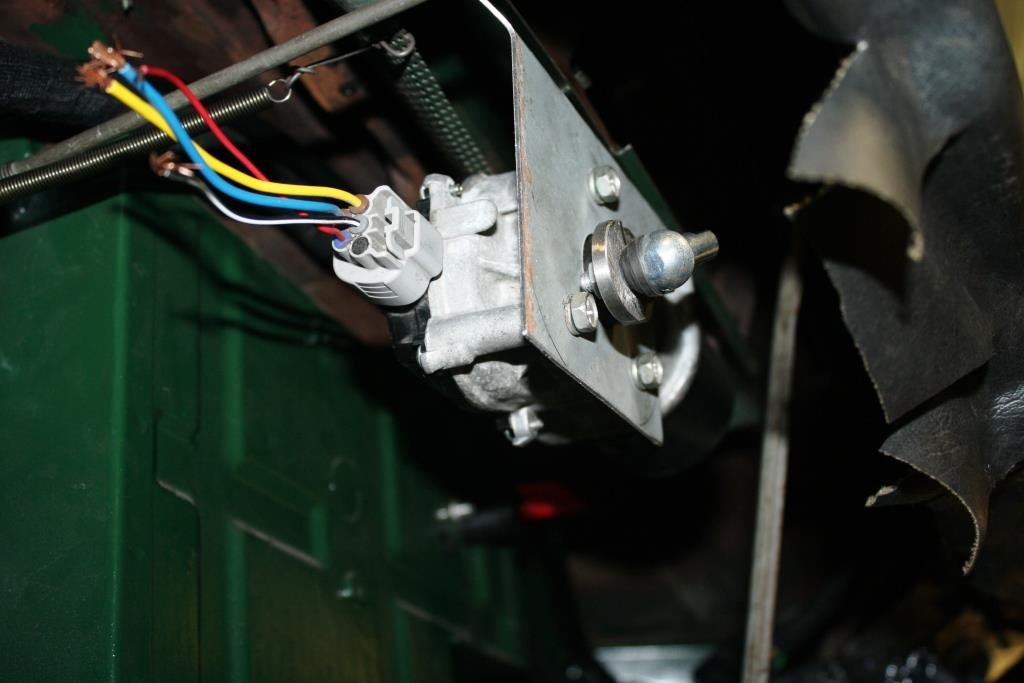
One last assembly on the bench…….
And it all tucks away, out of sight behind the dash.
Not only does it work it even has two speeds! (I’ll just have to hide the switch somewhere).
-
31
-
Bit of a bump for anyone who could come up with a repro carless sticker to match my Reggo sticker.

-
1
-
-
- Popular Post
- Popular Post
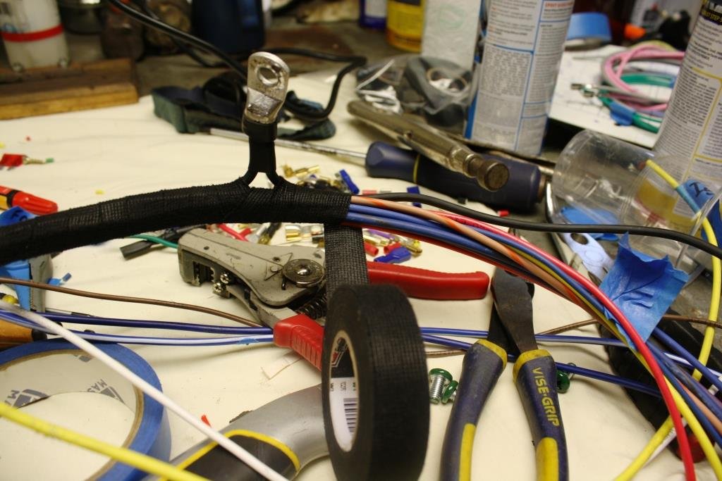
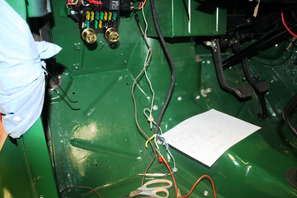
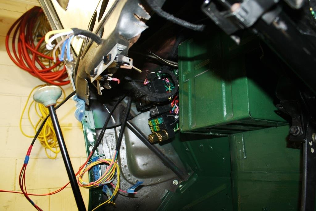
I managed to source some old style fabric tape and began wrapping the loom.
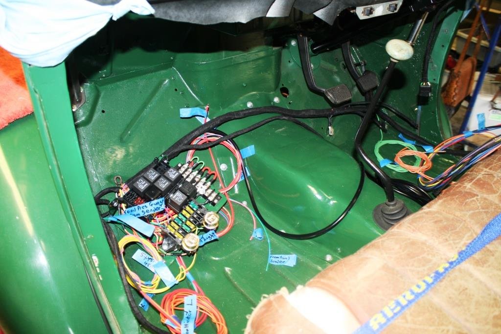
The main earth supply will be bolted to the earth strap bolt as it protrudes through the fire wall under the dash. (I’m running separate earths to the big current draining components.
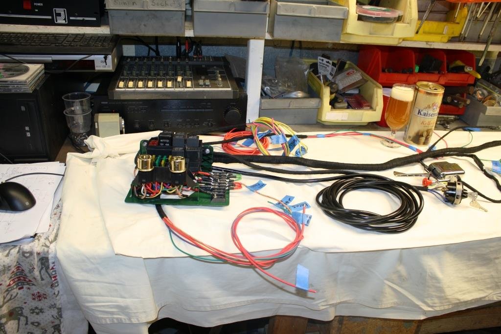
One more testing session and it’s all ready to fit to the car….
Looks messy at this stage……
….but it fits where it’s intended.
Hard to get a good photo of it sitting on the firewall on the passengers side. (I’ve got covers for the main components).
-
21
-
- Popular Post
- Popular Post
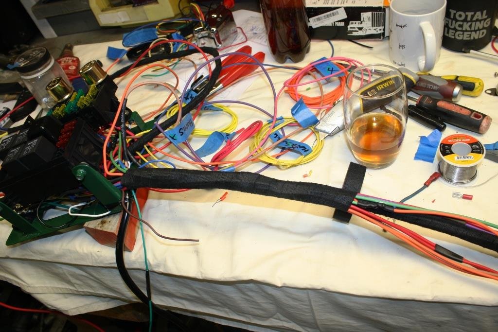
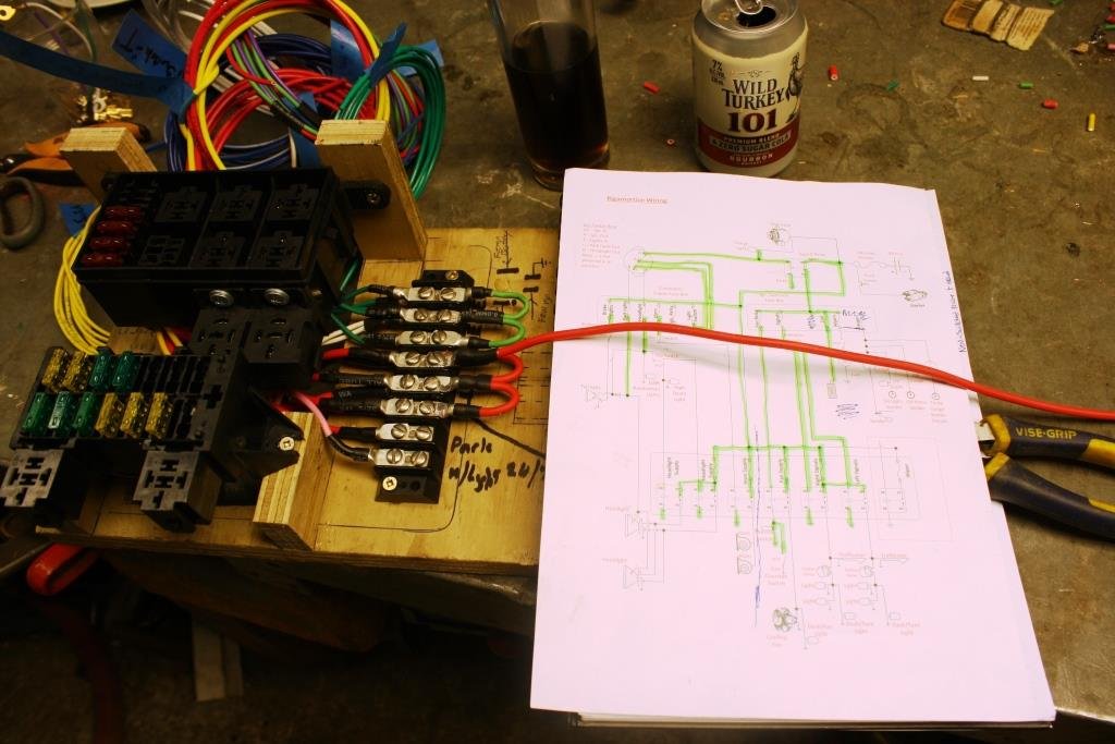
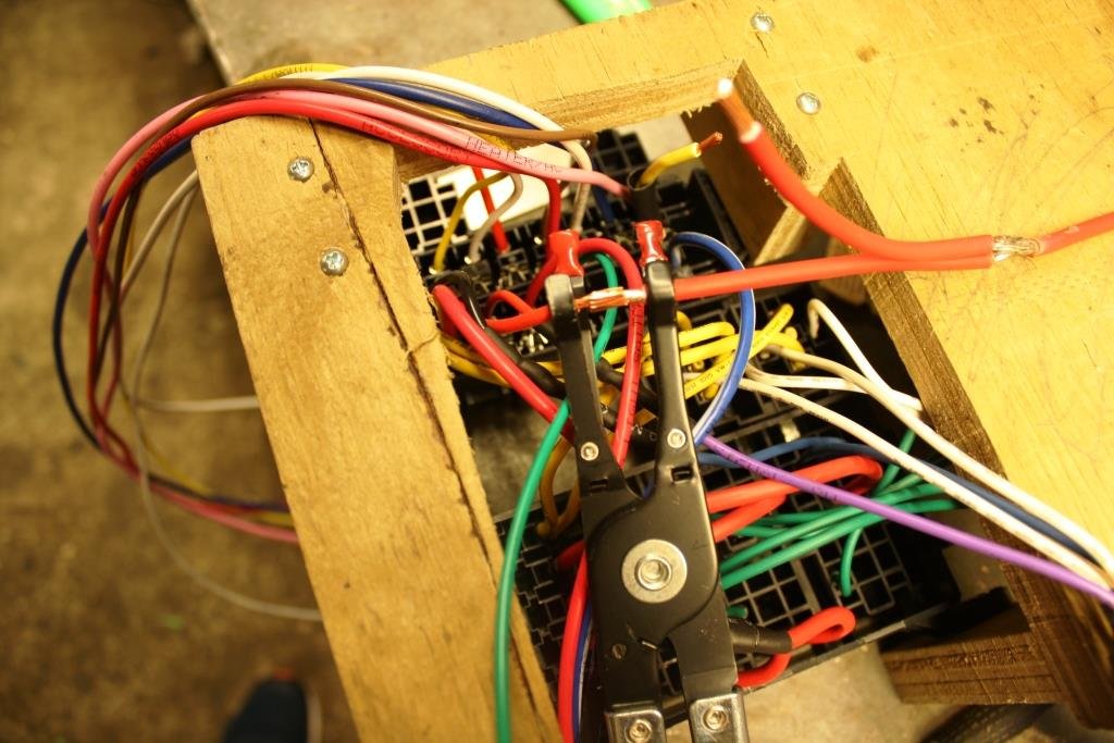
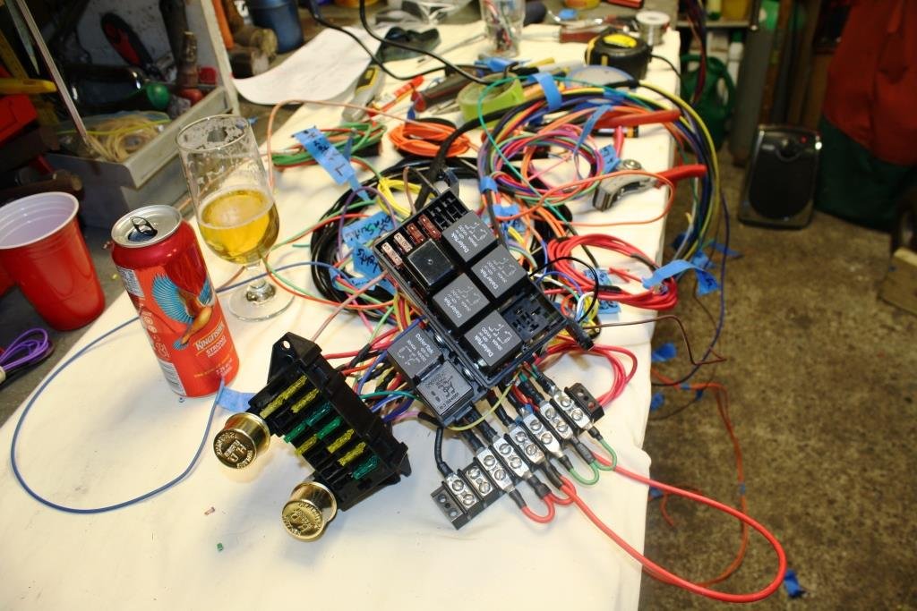
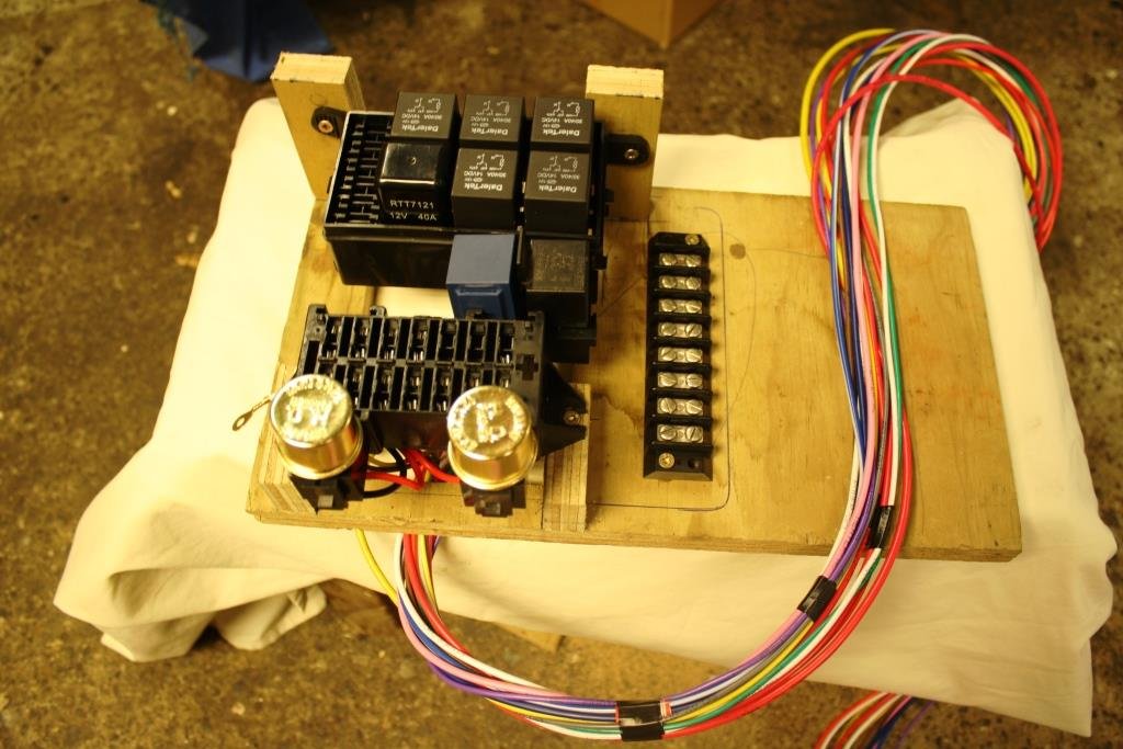
One thing I learnt about wiring years ago is that it always takes a lot longer than you’d think and most importantly liquid self-medication ensures a steady hand on the soldering iron.
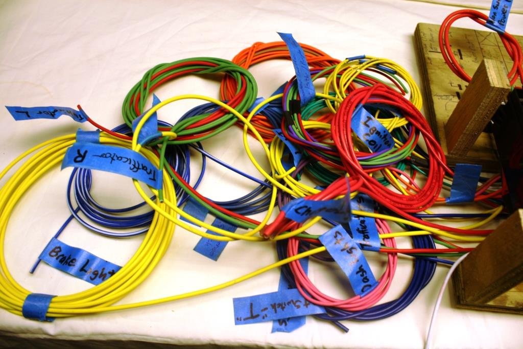
Started working my way through the circuit diagram making sure I was using the correct length and gauge wire while labelling everything.
Making great use of my $15 EBay wire holder when soldering, it’s rubbish quality but works surprisingly well.
I’m not a fan of crimping so everything is soldered and covered with glue lined heat shrink.
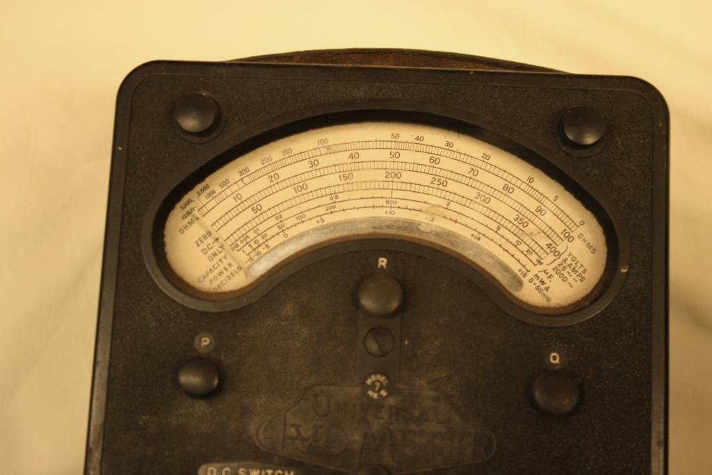
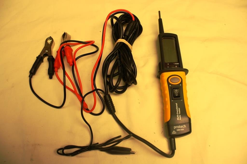
Next step was to power it all up and test with my trusty old Universal Avometer Model 7 Mk2 multi-meter…….
Crazy as it sounds the Avometer still works as well as the day it was made (it’s even older than me!) but to be honest my go to tool for car electronics has to be my new Multi-Function Auto Tester, they do everything including powering relays - I can’t recommend them highly enough.
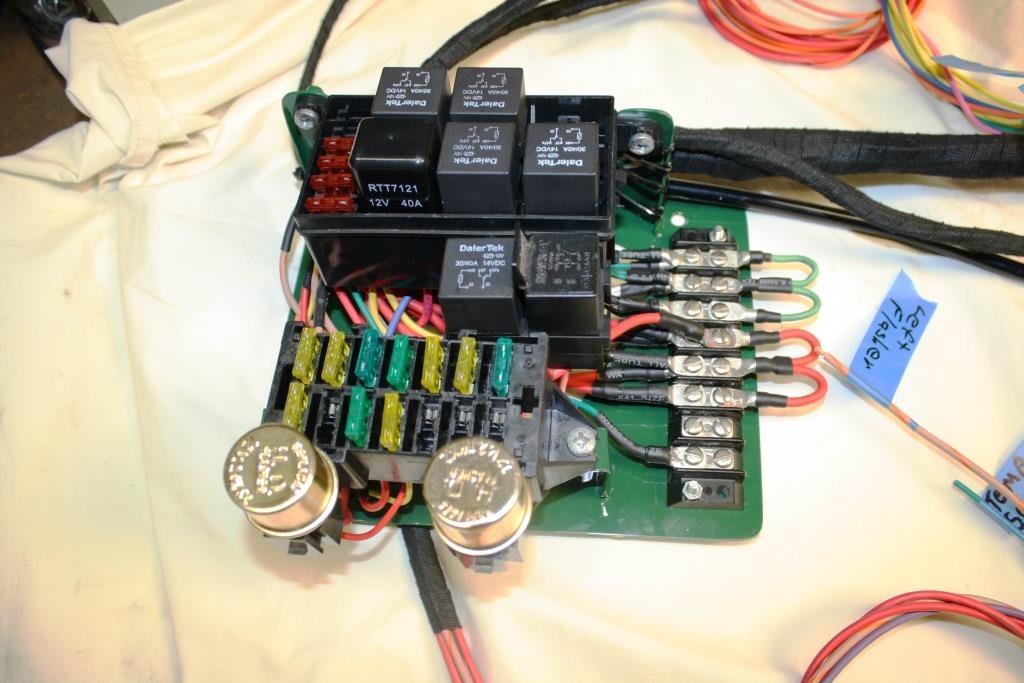
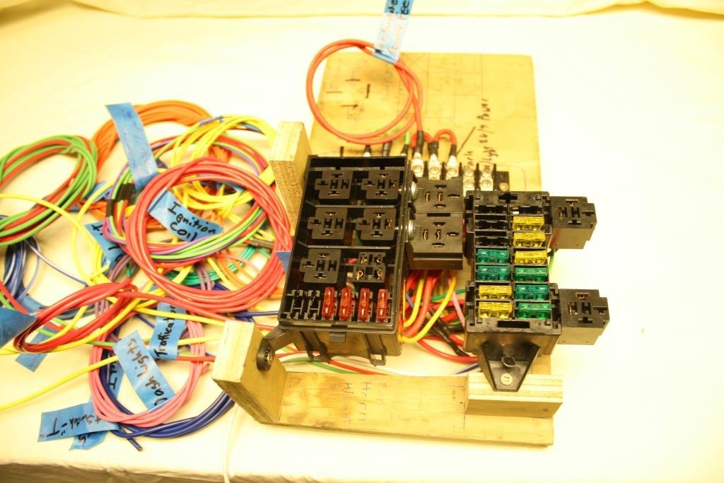
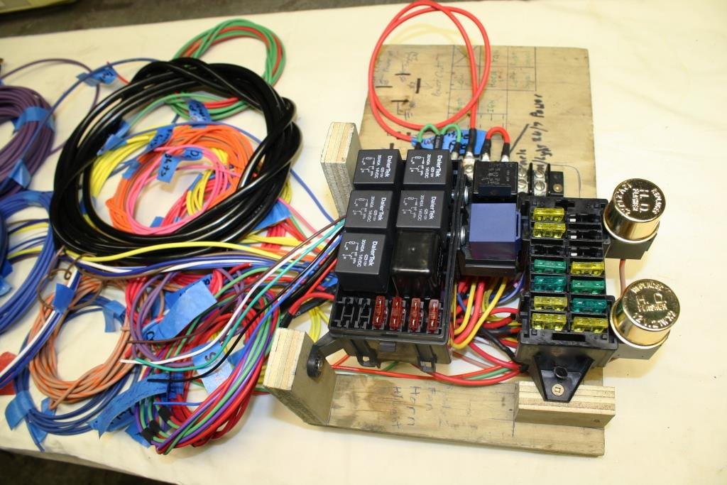
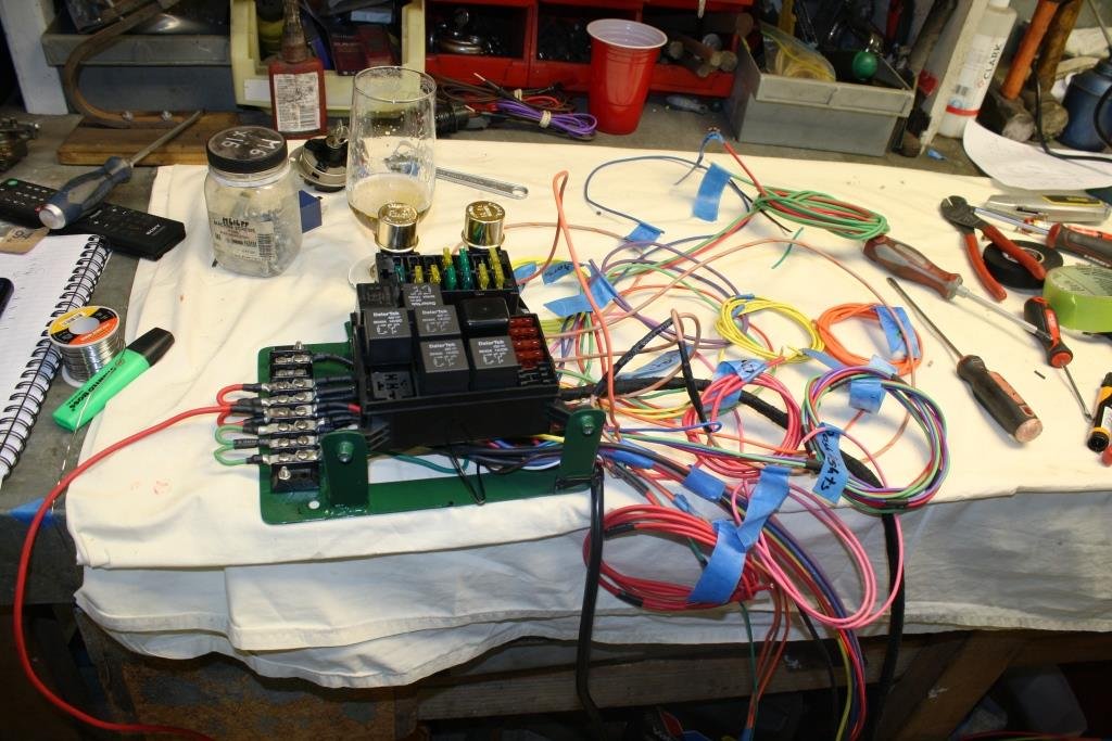
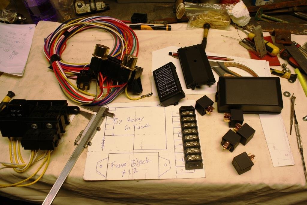
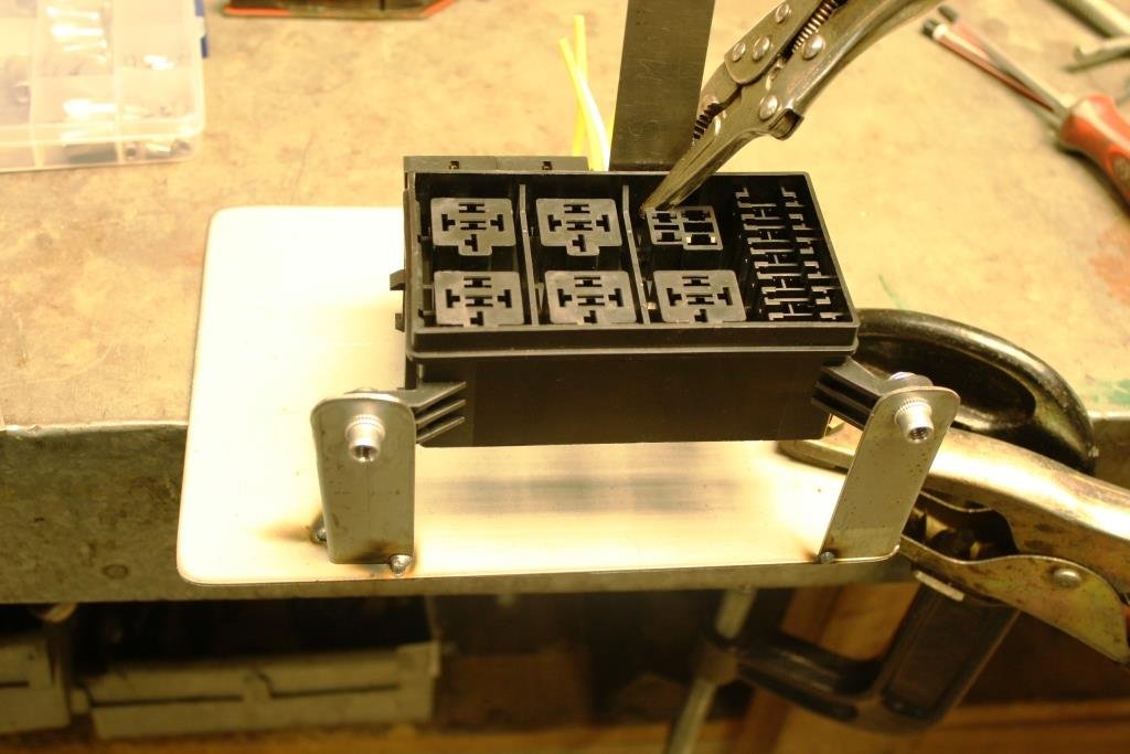
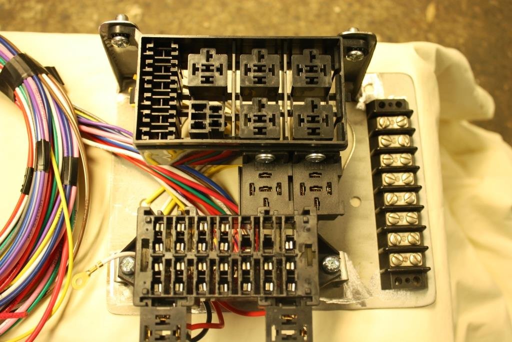
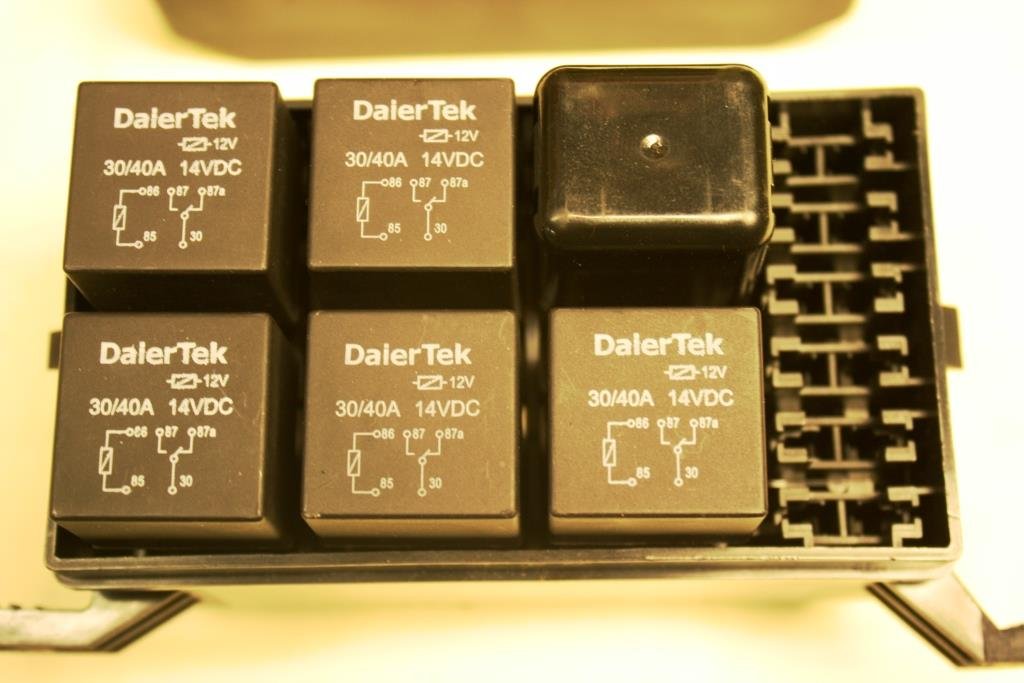
Removed a mess of wires, fuses & relays from the wooden jig………
…and mounted it on the freshly painted fuse/relay chassis.
-
22
-
- Popular Post
- Popular Post
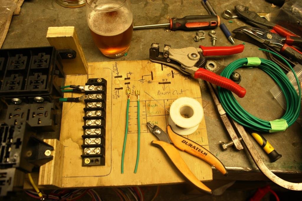
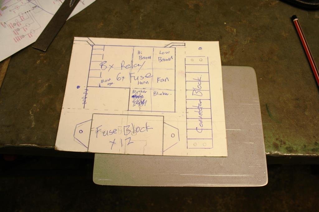
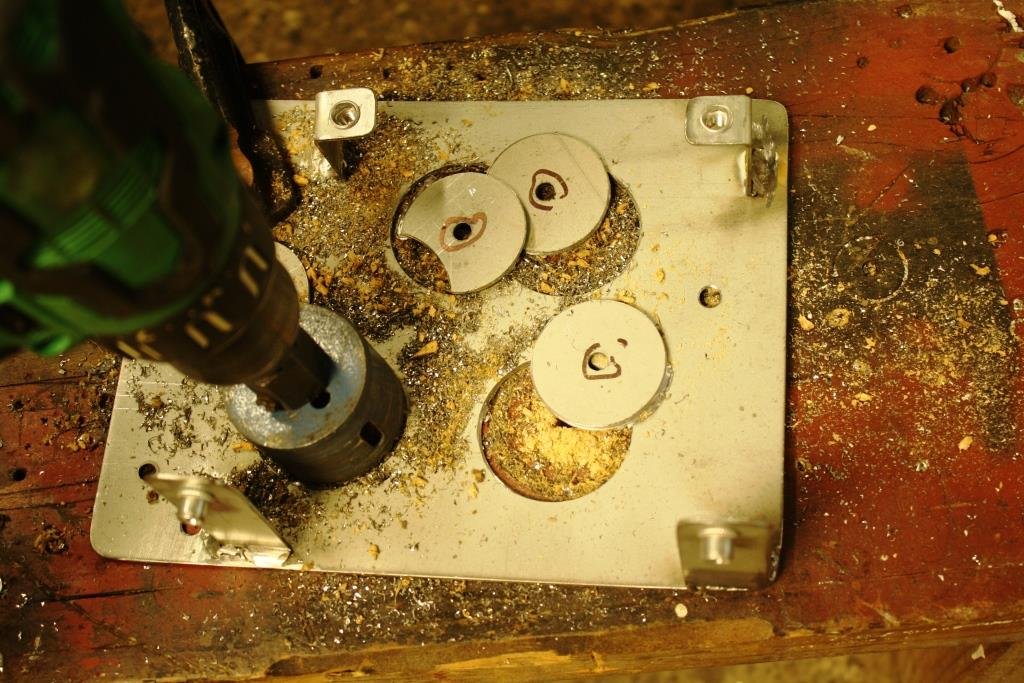
I decided to mount the fuse/relay boxes inside the car against the firewall on the passenger’s side. Made up the usual CAD template……
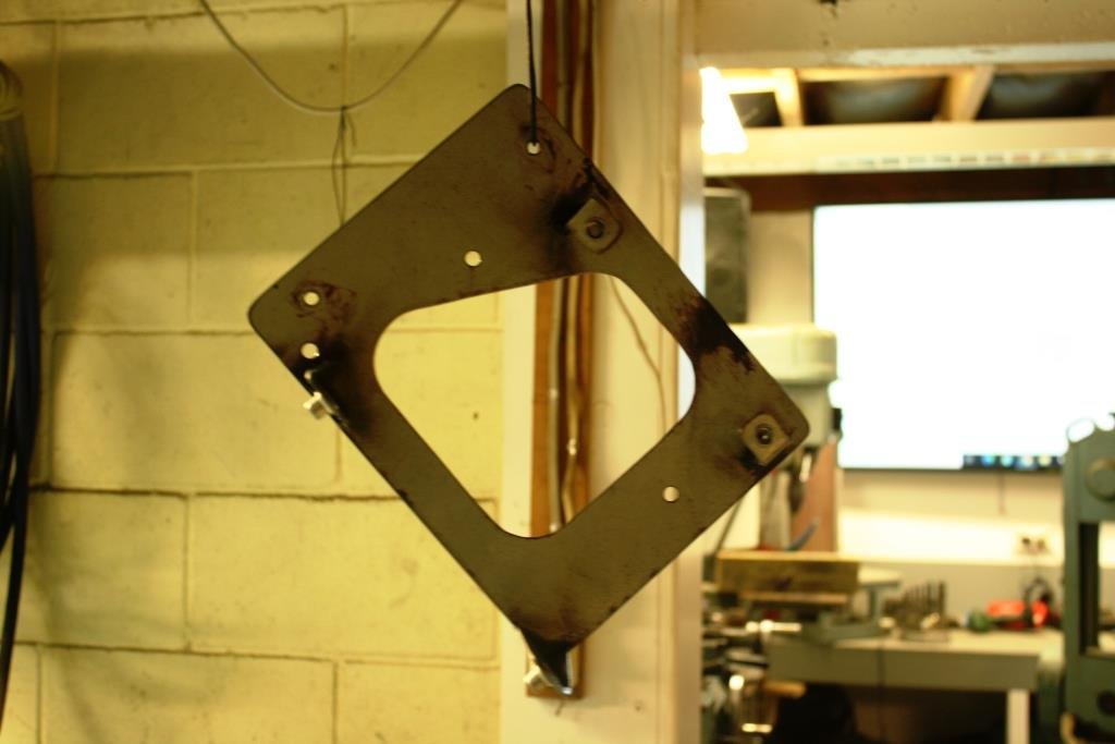
….and cut out a piece of zintex.
I drew up a schematic diagram, (I’m trying to document everything before the “al-simon’s disease” kicks in).
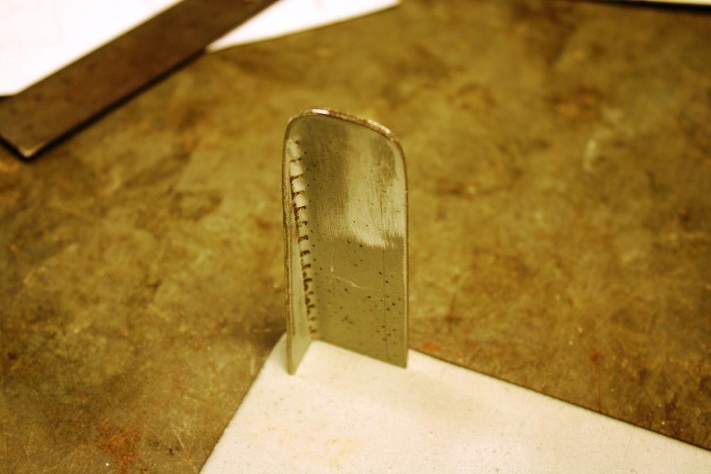
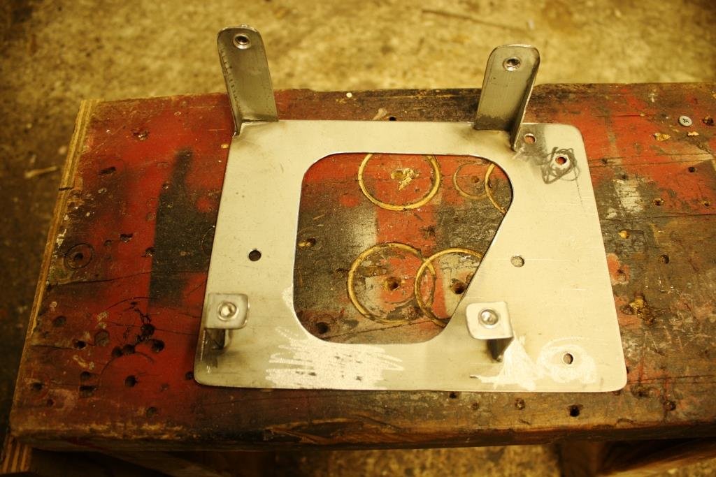
Bent up and tacked on some brackets to mount the hardware….
….love those riv-nuts.
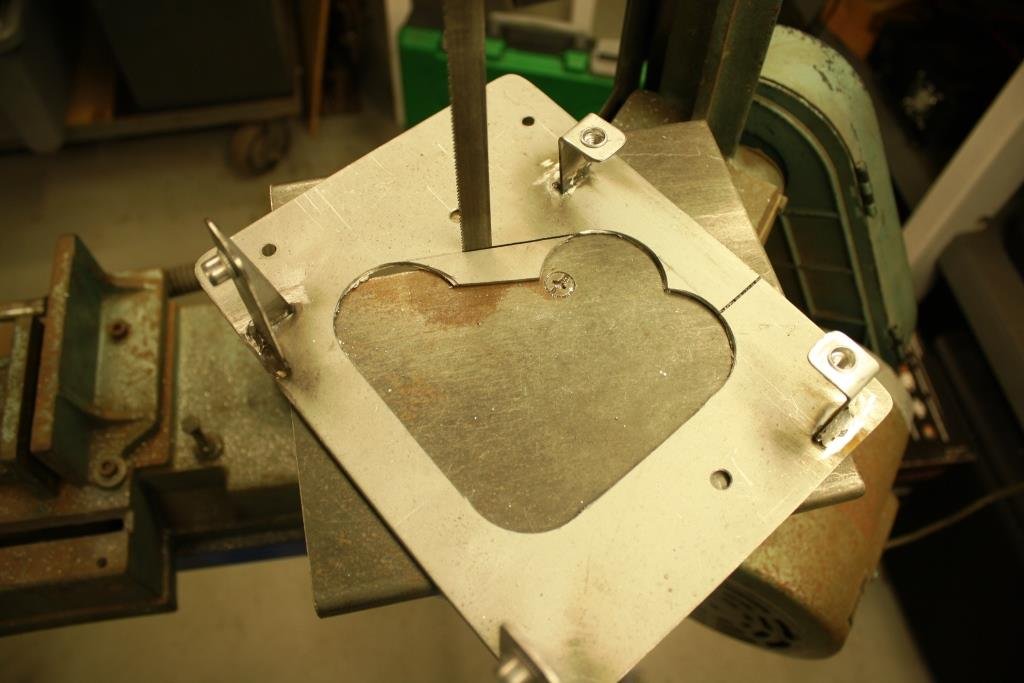
Cut the middle out…….
…….and checked everything for fit.
Primer applied and hung out to dry.
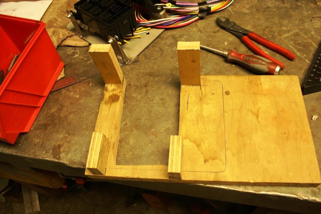
Next step was to make a plywood jig to hold everything and give me access to pre-wire. Plan is to make up the loom and most importantly test all wiring and switch gear before fitting to the car.
Time to fire up the soldering iron…
-
17
-
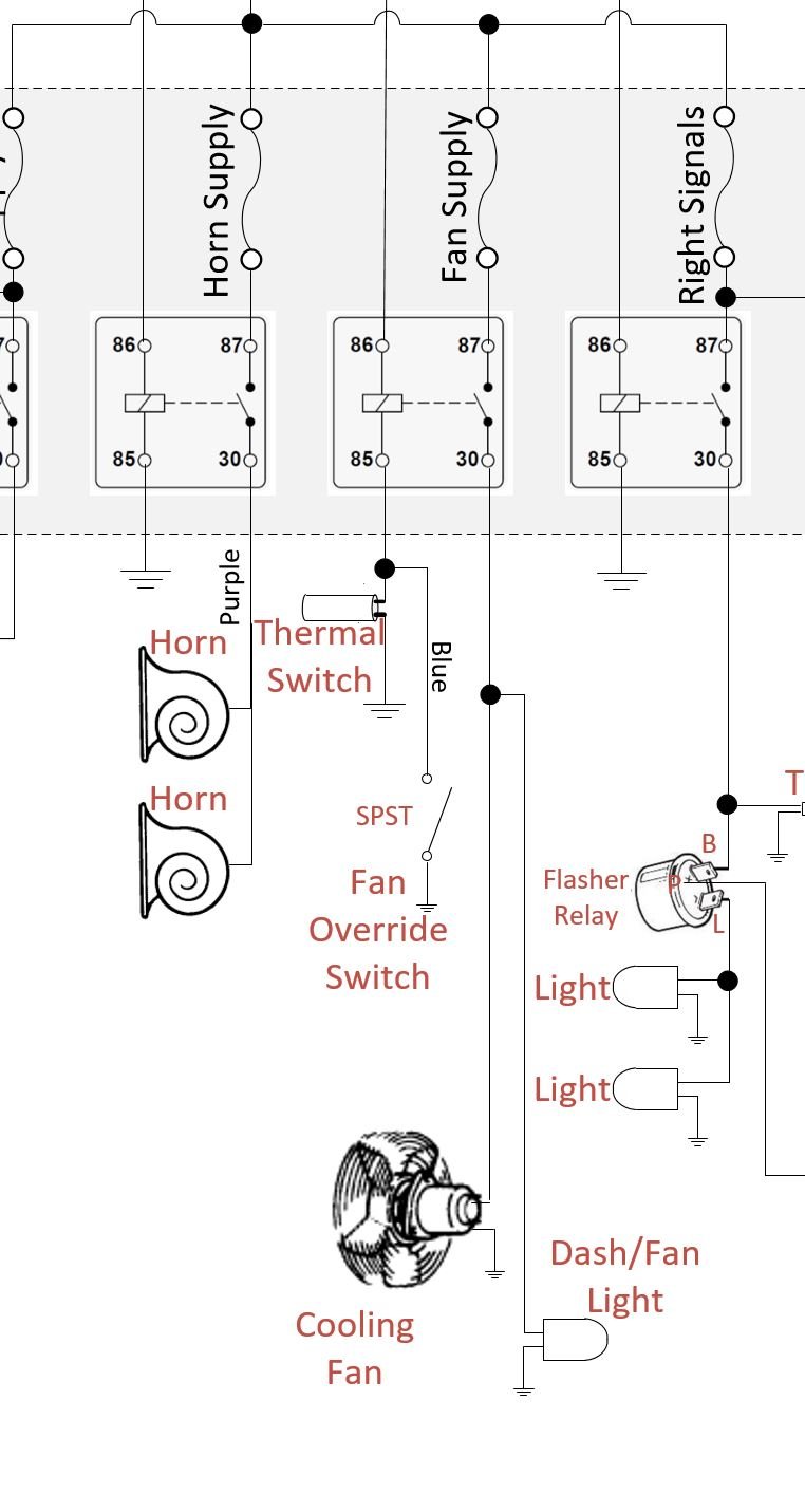
My thought process was to have the light light up only when the fan was actually powered up, .i.e I'd be covered in the event of a relay, fuse or switching failure.
-
2
-
-
14 hours ago, igor said:
Pleased to see that your revised wiring diagram retains the original twin horns.
Yes I love the horns, genuine Lucas ("Prince of Darkness") Windtones - they appeal to my passion for totally impractical solutions to problems that never really existed in the first place!
Only issue is they currently sound like a pair of cats being slowly strangled, I'll have to do some research on how to set up their contact points and then tune them.
-
44 minutes ago, Kiwibirdman said:
The only gotcha with that is if your fan is in front of the radiator it will act as a generator and the bulb will glow at higher speeds. Not a big issue, the light on the dash board of the Holden is fairly bright at 70 mph.
@chris r If the bulb was wired behind the thermo switch and was earthed it should work OK for automatic use, it wouldn't come on when manually activated.
Snap!
I've just had an auto-sparky mate point out the same re the fan acting as a generator, shame I didn't have the room to mount it as a puller. I might do a suck it and see on this one, if it is an issue I'll put a big diode on the fan supply after the feed to the light.
-
11 hours ago, chris r said:
Revthe fan Switch side looks good/it'll work as drawn
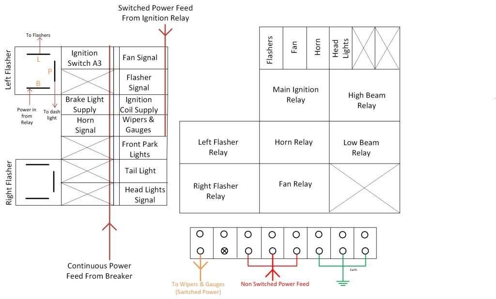
@sr2what do you want the light to do?
If you want it to indicate when the fan is running then connect it to the 30 terminal of relay/in parallel with the fan itself
If you wire it as drawn the relay/fan will always be on as it'll earth out through the bulb
You're on to it mate. The fan light is supposed to be on when the fan is running. I should have it connected to pin 30 on the relay, (I've been going bat shit crazy staring at it all for the last few weeks!).
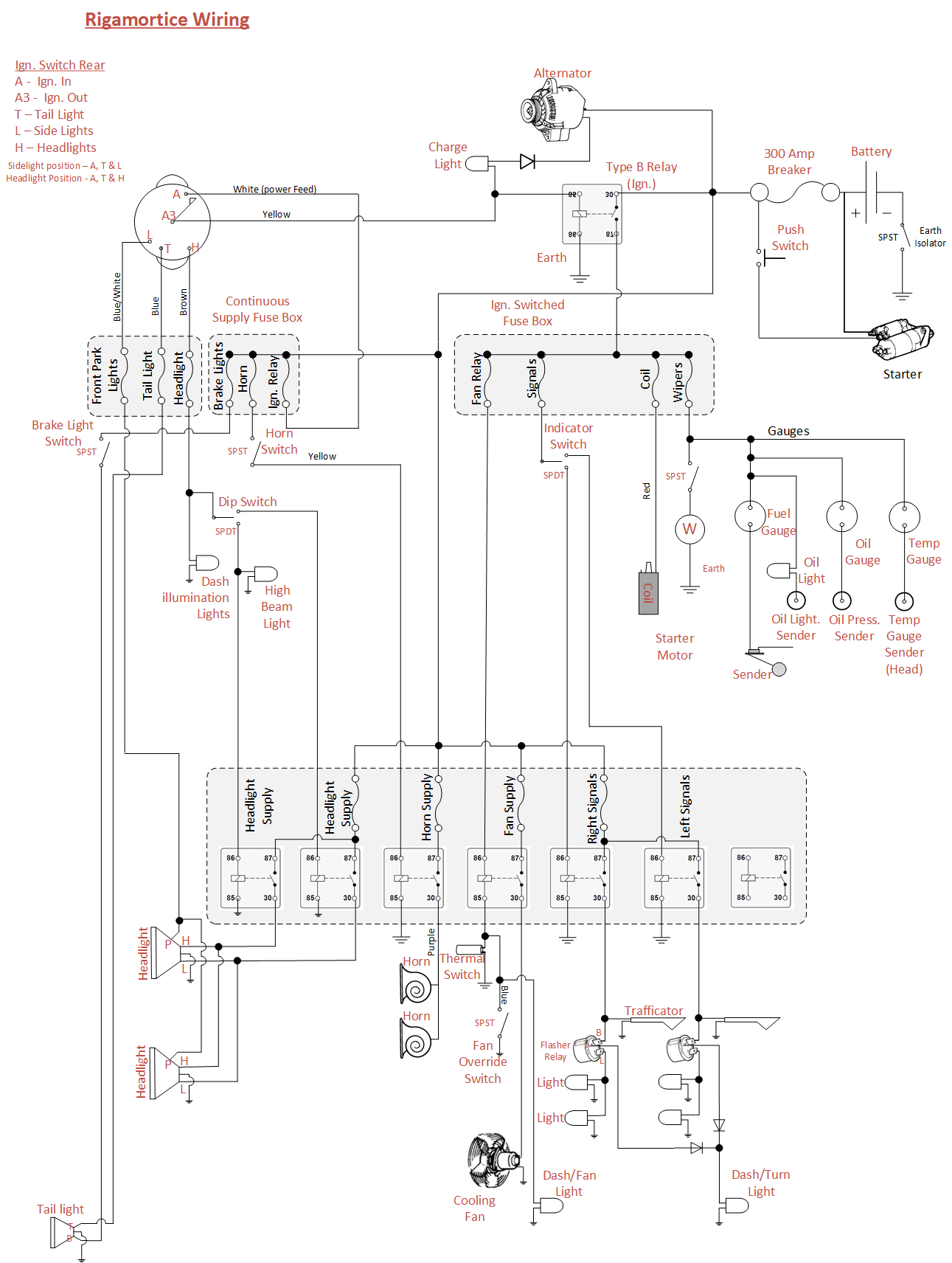
Revised version below, the bulb will be a LED so there should be no earth issue.
-
12 hours ago, Thousand Dollar Supercar said:
In order for the fan override switch to be able to force the fan to run, you'd need the thermal switch to be normally open, and the dash/fan light would have to be on whenever the fans were NOT working. I think. I did have some gin a bit earlier.
LOL, gin always makes me highly intelligent, nearly as much as 101 Wild Turkey.
You're right there's something funny with the fan on light/override switch setup.
-
- Popular Post
- Popular Post
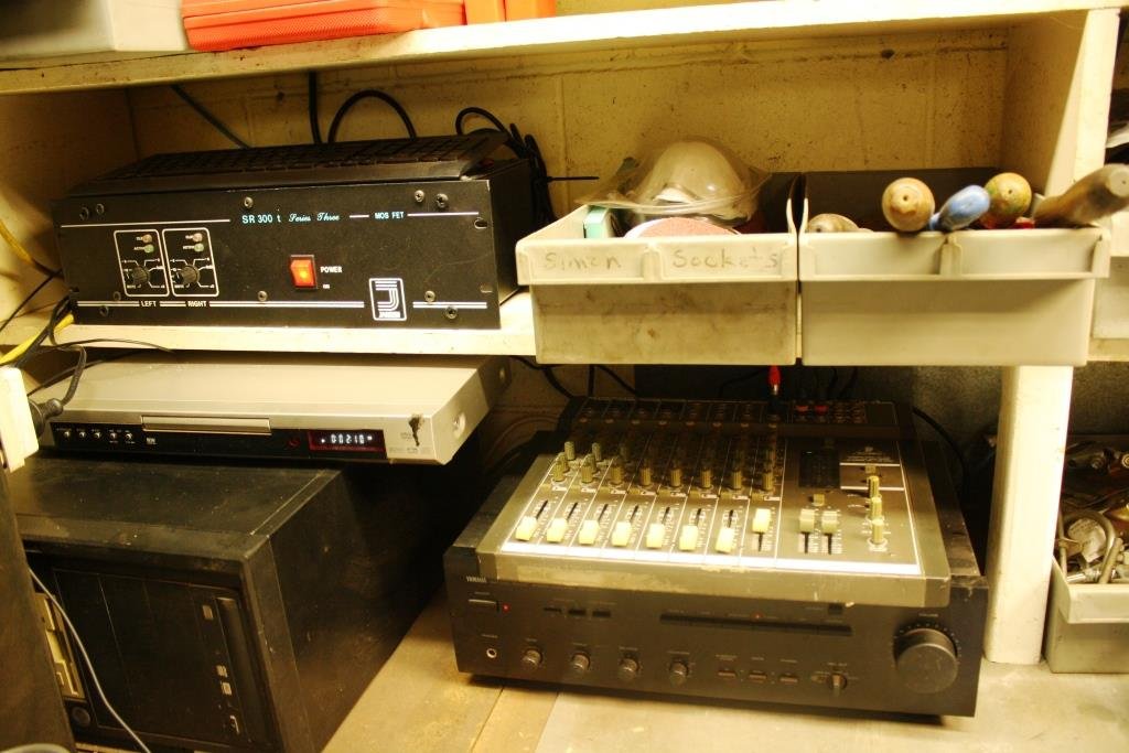
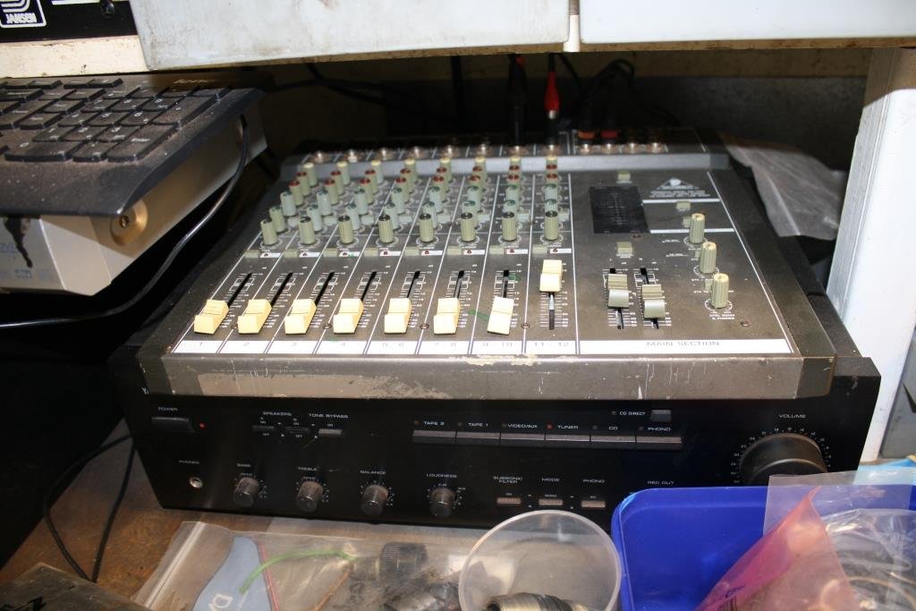
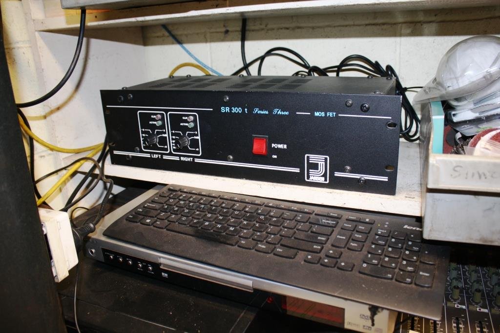
Rigamortice and I are recovering in isolation after a recent bout of retail therapy.
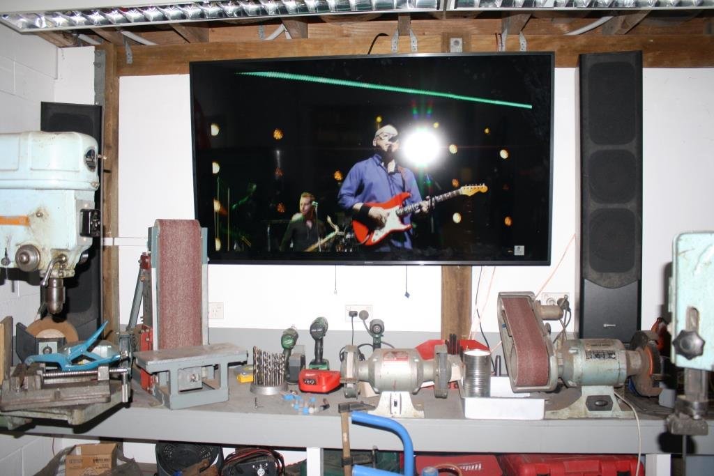
Decided the ‘world famous’ sr2 man-cave sound system needed a retro upgrade.
Found a cool old 12 channel desk.
And a vintage NZ made Jensen 300T power amp.
We ditched the Wharfdale PA cabs in favor of column speakers but kept the powered sub....
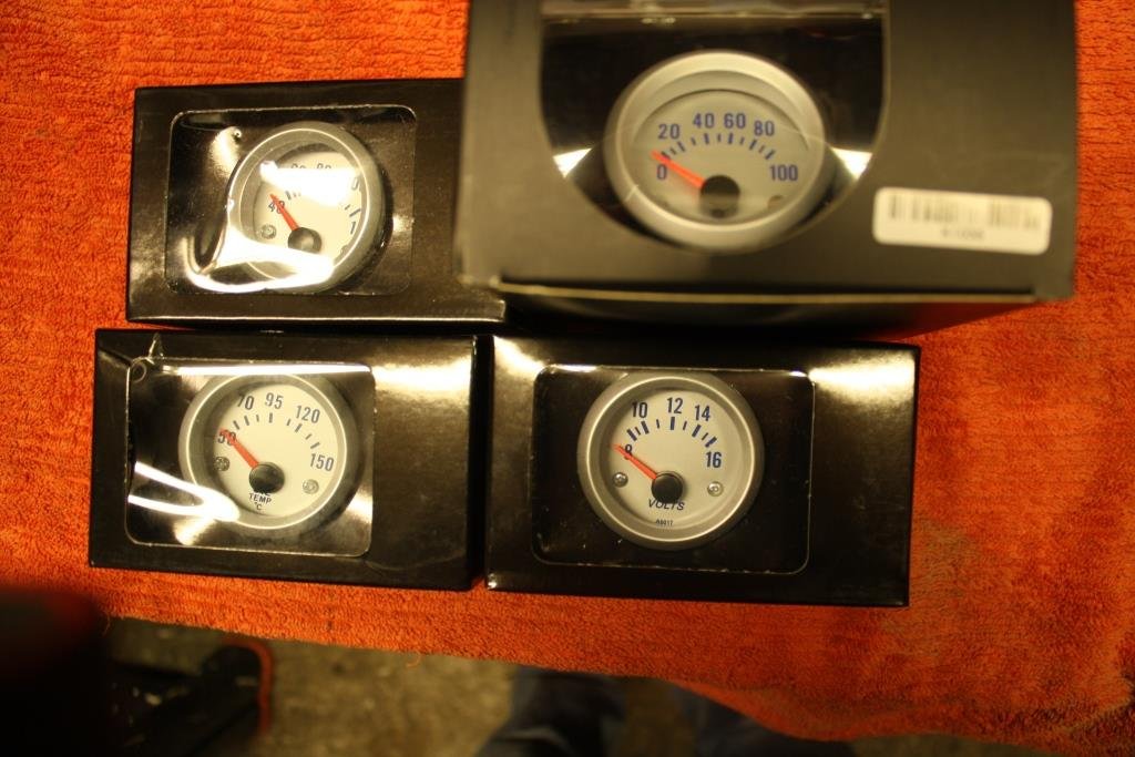
Bought a set of gauges on line, I’ll just have to find a place to keep them hidden from view but still be available when I need them.
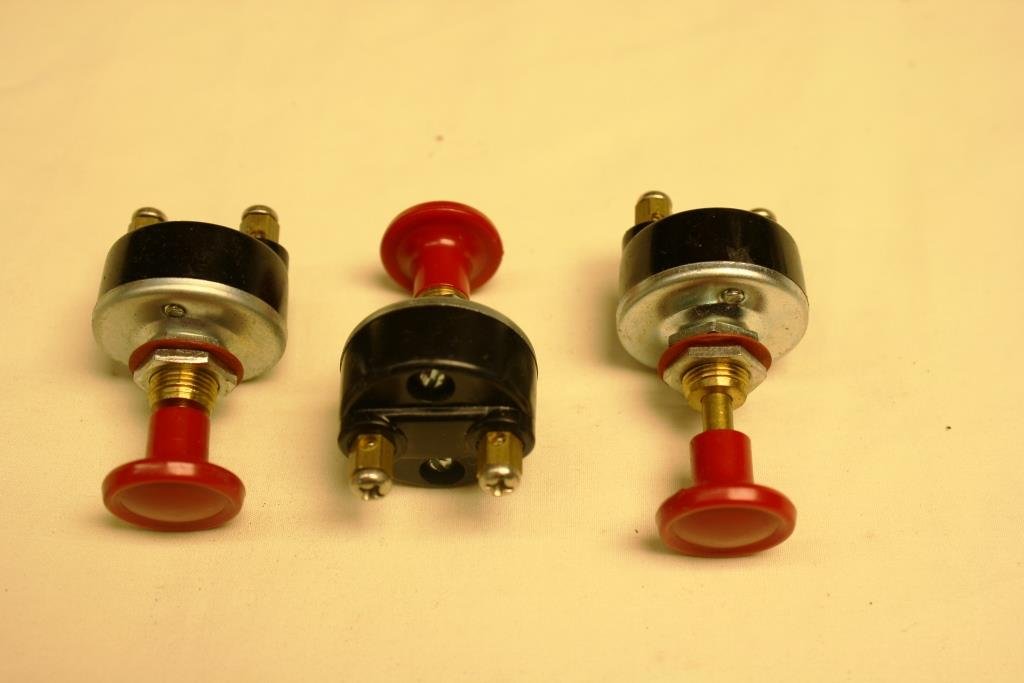
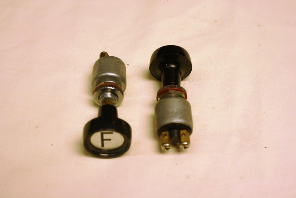
Found some cool new old stock push/pull switches……
…and another pair with a big “F” on them…..(don’t tempt me!).
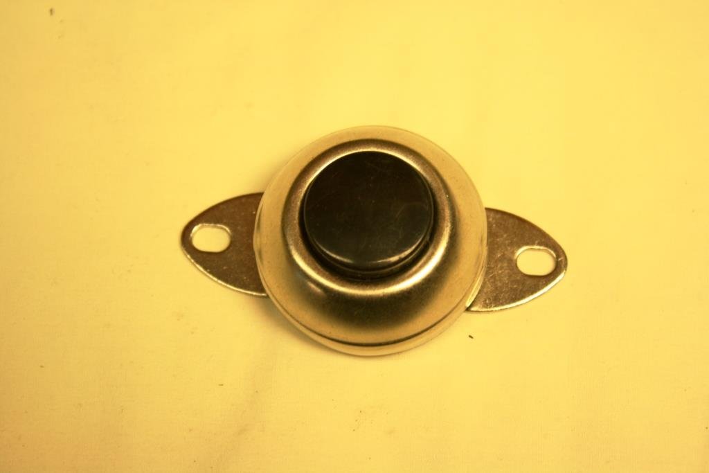
This should do for a horn button….
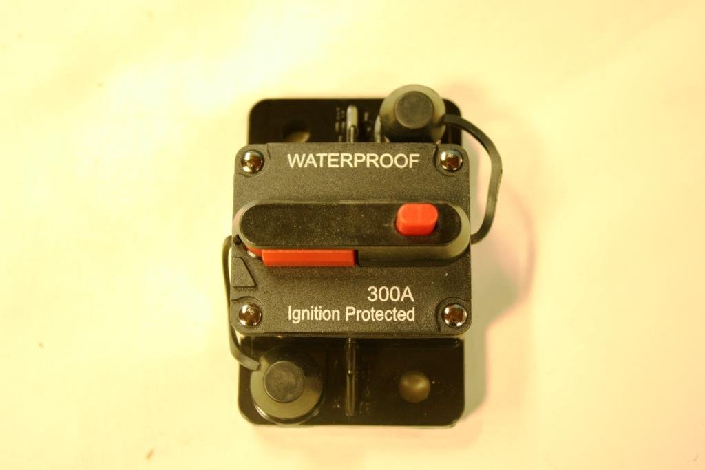
Rather than running a fuseable link on the main power supply I settled on a big, grunty marine circuit breaker.
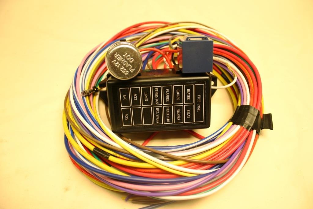
I found a 12 circuit ‘hotrod wiring kit’ for a too good to be true price on line, (yes I bloody know…..). Have to say I was a little disappointed when I discovered that it was wired incorrectly and the instructions were written in a form of “Engrish” that neither Rigamortice nor I could comprehend!
The wire and hardware will be handy however.
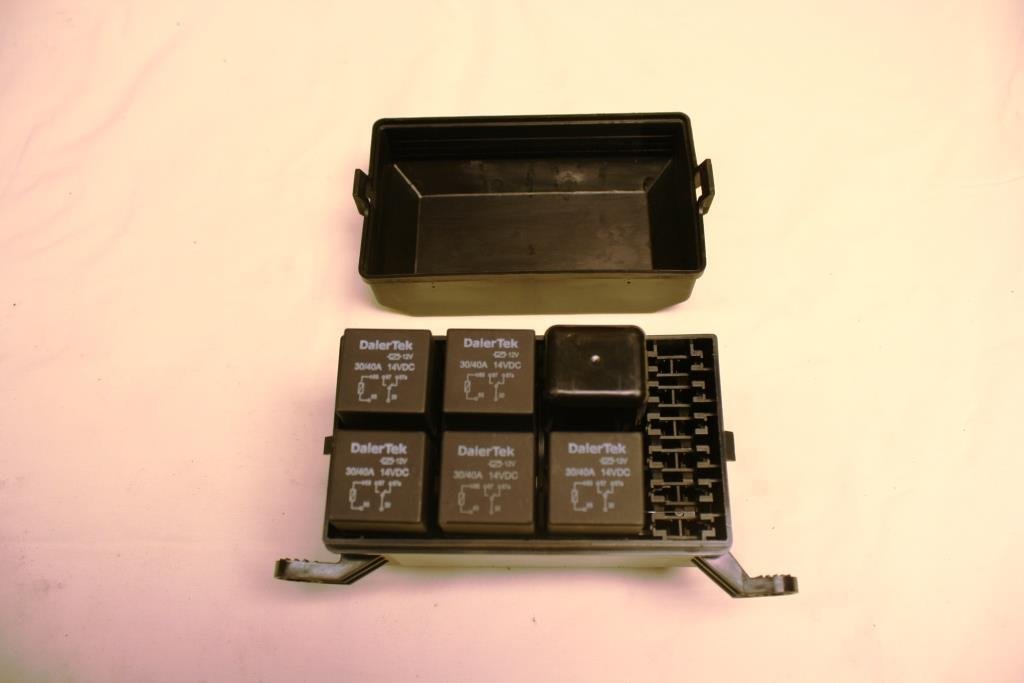
I’m a little wary of running modern amperage through 70 year old switches so I found a box full of relays and fuses that should make things a little safer.
Best score of all was this collection of leftovers from a big wiring job. More than enough to wire the old girl up.
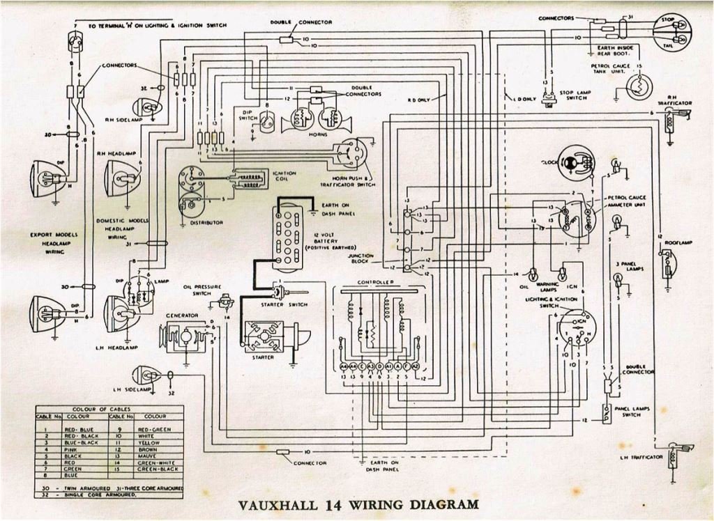
Time to make a start on the wiring, I don’t think the original diagram will be much help but it sure is cool.
I’ve been working on drawing up a circuit diagram (pronounced ‘circulating diaphragm’ after a few Wild Turkeys) for a while. Plan is to have a box of relays to minimise the current through the 70 year old switches while having both control and supply circuits individually fused, possibly a bit overkill but as I always say “it’s always harder to put the smoke back into the wires”!
After a number of late nights and a considerable over consumption of Wild Turkey this is hopefully the final version. If anyone from the Oldschool Brains Trust can spot any mistakes or suggest any improvements please let me know.
-
19
-
- Popular Post
- Popular Post
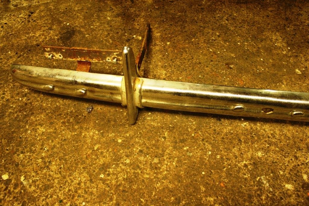
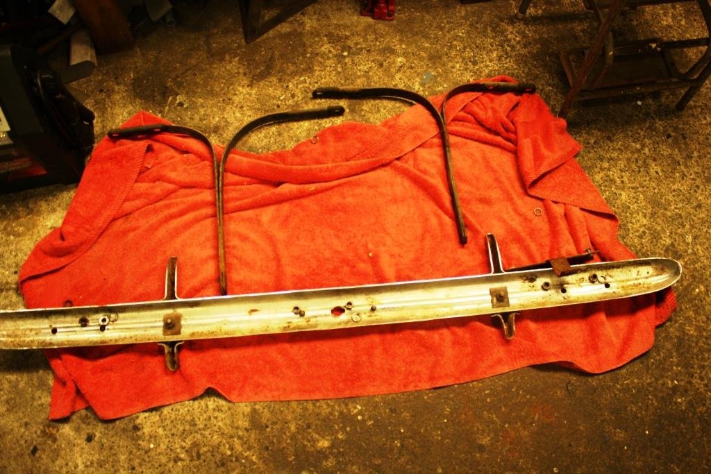
Time to pull the front bumper out of the shed…
I’m not that keen on where the number plate was mounted, I think it’ll end up in the middle under the bumper.
Stripped it all down….
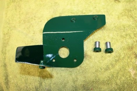
It’s mounted on bumper irons made out of spring steel, looks like the port side was in the wars at some stage…..
Spent an evening cleaning parts up on the wire buff…
Love the old bolts and countersunk star washers…..
Once again everywhere you look in the world acclaimed (in Milford) Sr2 Man cave there painted car parts hung out to dry…..
I managed to score some new bumper rubbers from Basis, what a great source of old style rubber trims and fittings they’ve recently moved from Christchurch to Auckland.
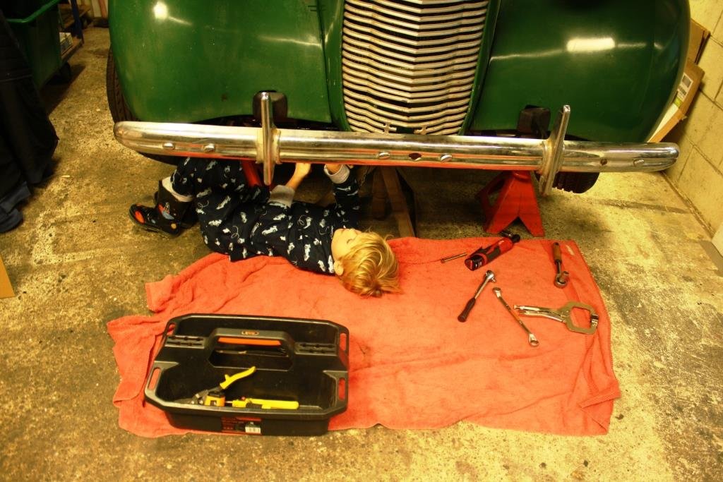
Our professional racing driver sneaked out after bedtime in his racing car jarmys and new gumboots to give “Gramps” a hand - you’ve got start them off young.
Looks like’s he parked up his tools, Police helicopter, crash helmet, life jacket and a couple of trucks where the back seat needs to go!
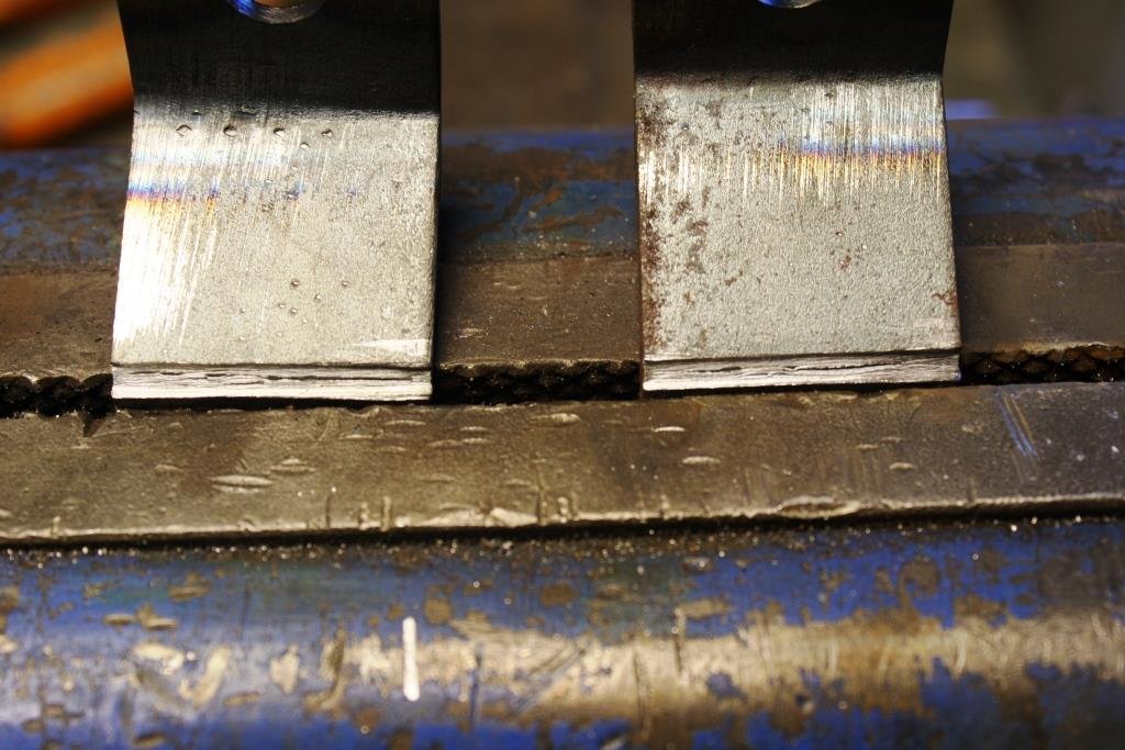
Made up some brackets using the cut, bend and weld method my Dad taught me when I was a kid.
Front number plate now mounted nice and low in the middle.
-
21
-
On 18/09/2023 at 19:38, Bistro said:
Looks crazy but I can vouch for it working. I ended up having to weld a piece of round to a drill to get the depth through the wood.
-
Is it a 2, 3 or 5 wire alternator?
")
-
- Popular Post
- Popular Post
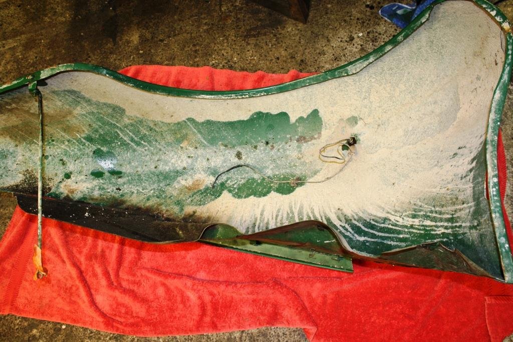
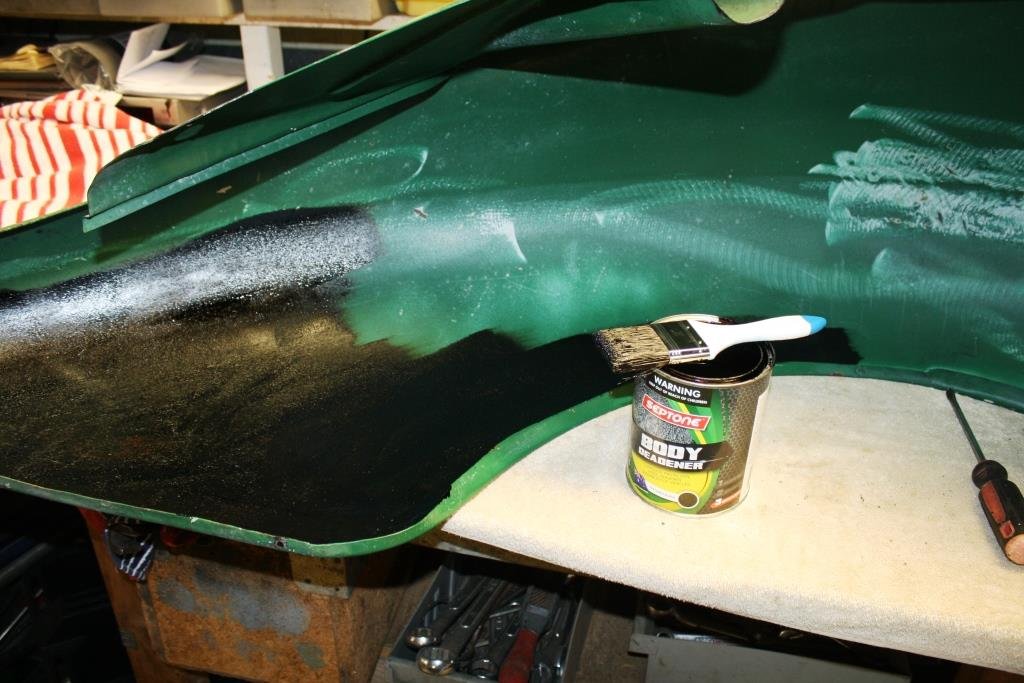
Thought it was about time I did something to Rigamortice’s outside for a change so I pulled the front guards out of the shed and started cleaning…….and cleaning………
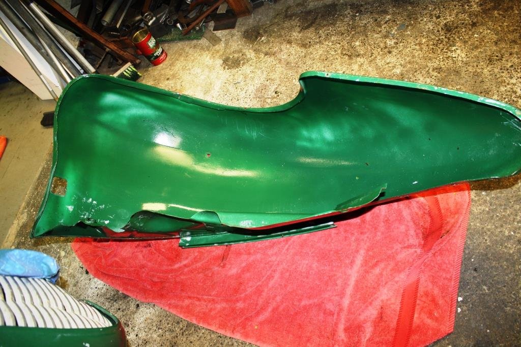
After a lot of elbow grease I managed to remove god knows how many years of accumulated road muck and they didn’t come up too bad.
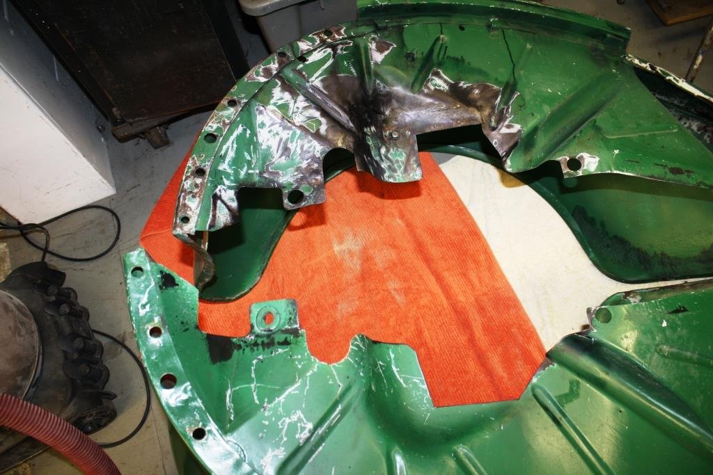
I had to do a little cutting and welding on the inner fenders to clear the front end………
Managed to source some Septone underseal (from Supercheap - believe it or not) and slapped on a couple of coats
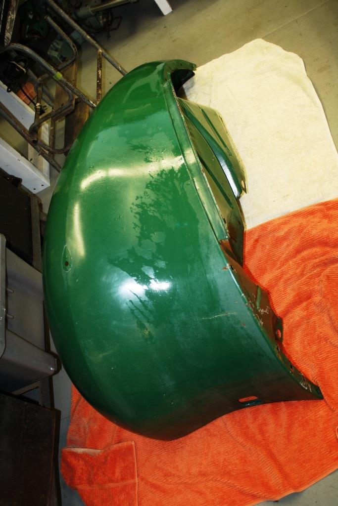
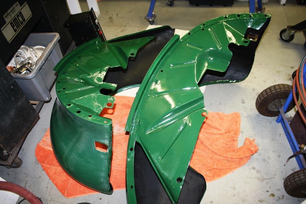
Painted the inner guards……..
And spent an evening aligning all the panels and bolting the front guards on.
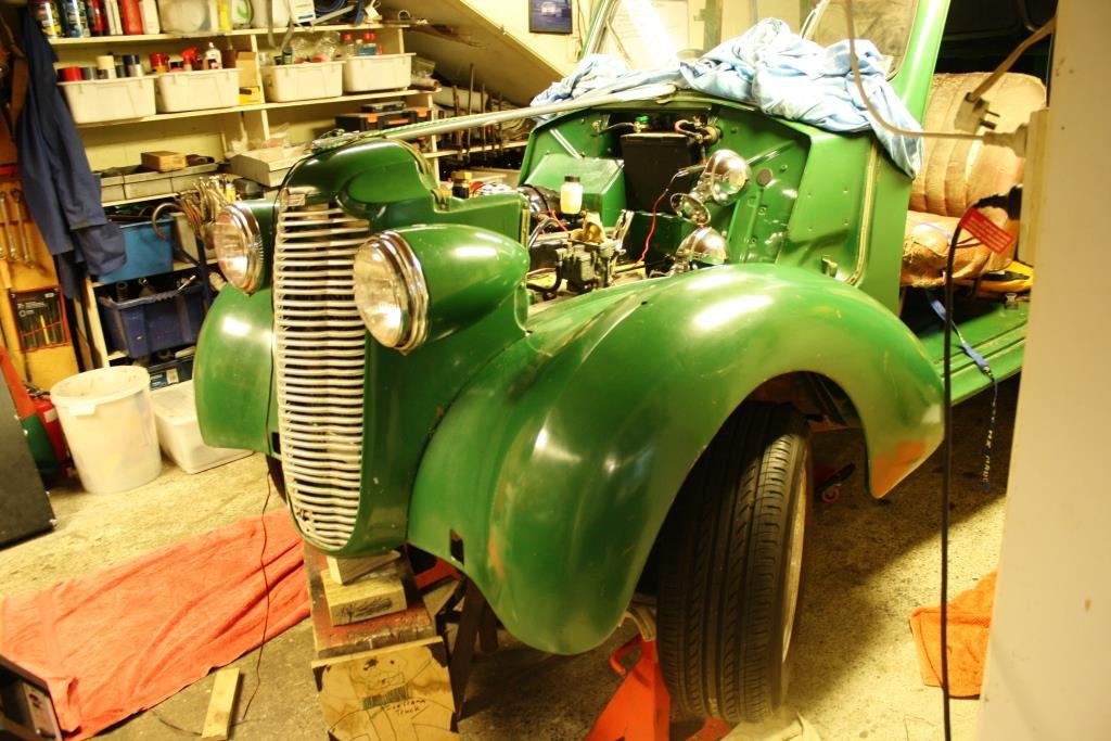
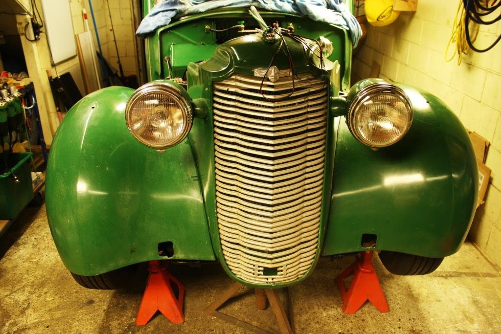
Have to say I still love the 70’s Cheviot mags, glad I made the call not to refurbish and to keep them ‘oh naturale”.
One more full-frontal auto porn pic!
-
23
-
- Popular Post
- Popular Post
As I mentioned earlier the steering wheel needed to come closer to the dash.
Originally the J14 Vauxhall had a solid steel steering shaft that went from the steering wheel to the steering box; essentially you were driving around with a steel lance that went from right up the front of the car to 6 inches away from your chest. The mind boggles at the thought of having an accident in such a setup with no collapsible column, no seatbelts and no crush zones!
With the narrowed Austin steering rack mounted behind the HR Holden cross member Rigamortice’s steering column needs two universal joints to get past the engine. This addition of an intermediate shaft at an angle to the main steering column gives some collapsibility in an accident. Combined with seatbelts it’s a big improvement on 1947 safety standards.
I’m never going to make Rigamortice as safe as a modern car but I’m still keen on staying alive for as long as possible and am looking forward to living long enough to become an obnoxious, cantankerous & grumpy, dirty old man!
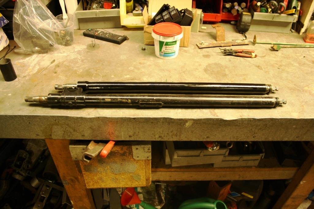
Luckily most of the old English mass produced cars used the same splines in their steering systems so it’s easy to mix and match. I managed to source a shorter Triumph steering shaft and I shortened an original tube to fit to give me the desired length.
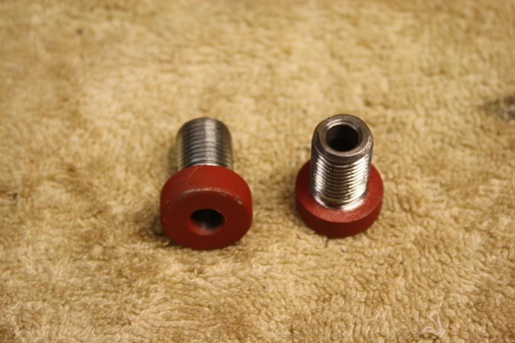
Original and shortened Triumph 2000 steering columns……..
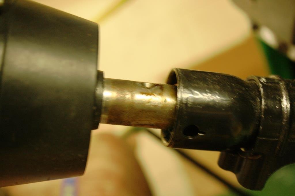
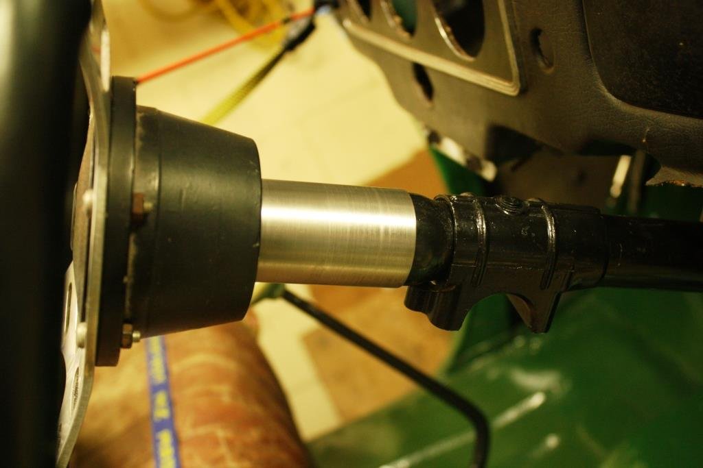
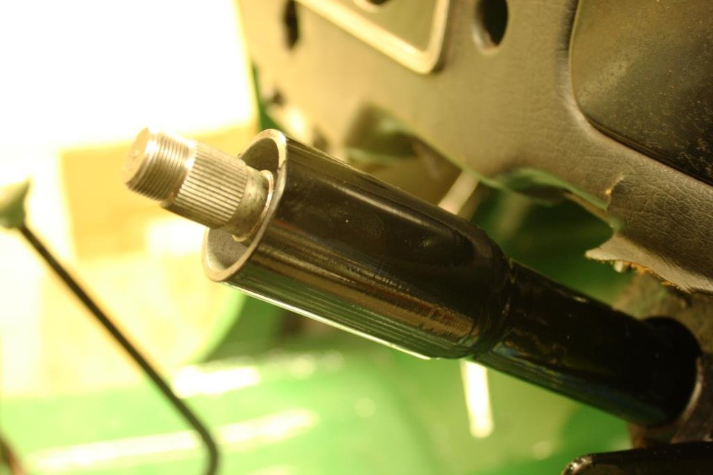
Only problem was this ugly gap between column and steering wheel…
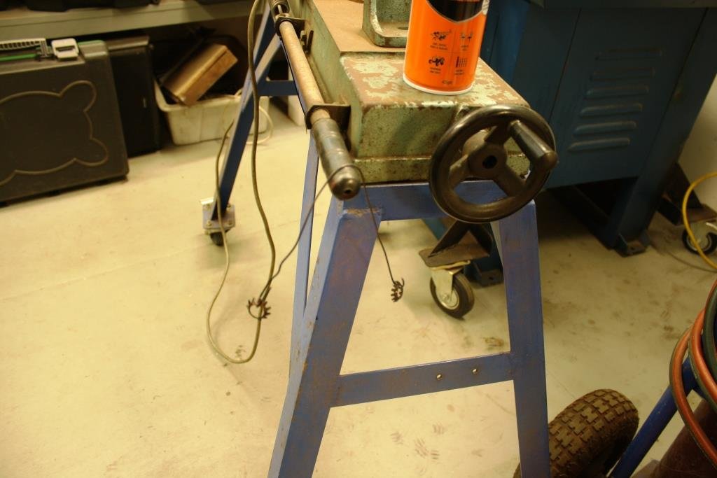
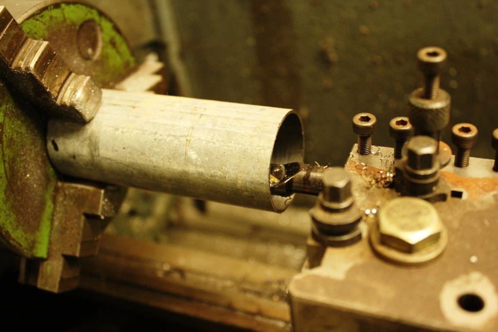
Being a tight bastard (short arms & deep pockets) I started with a scrap piece of galv. water pipe.
Stuck it in the lathe and poked a boring bar down it……..
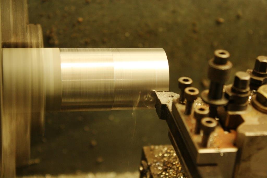
Cleaned up the outside….
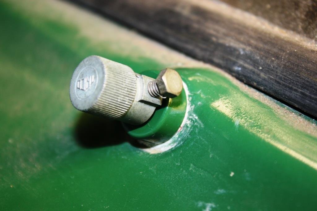
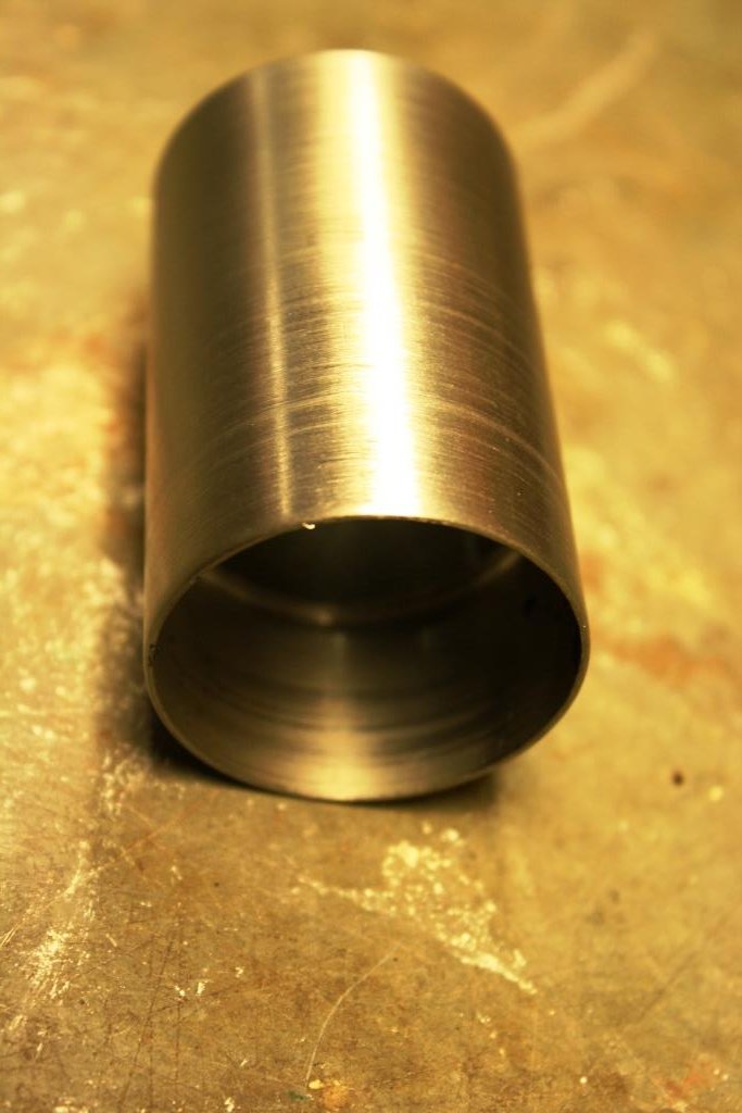
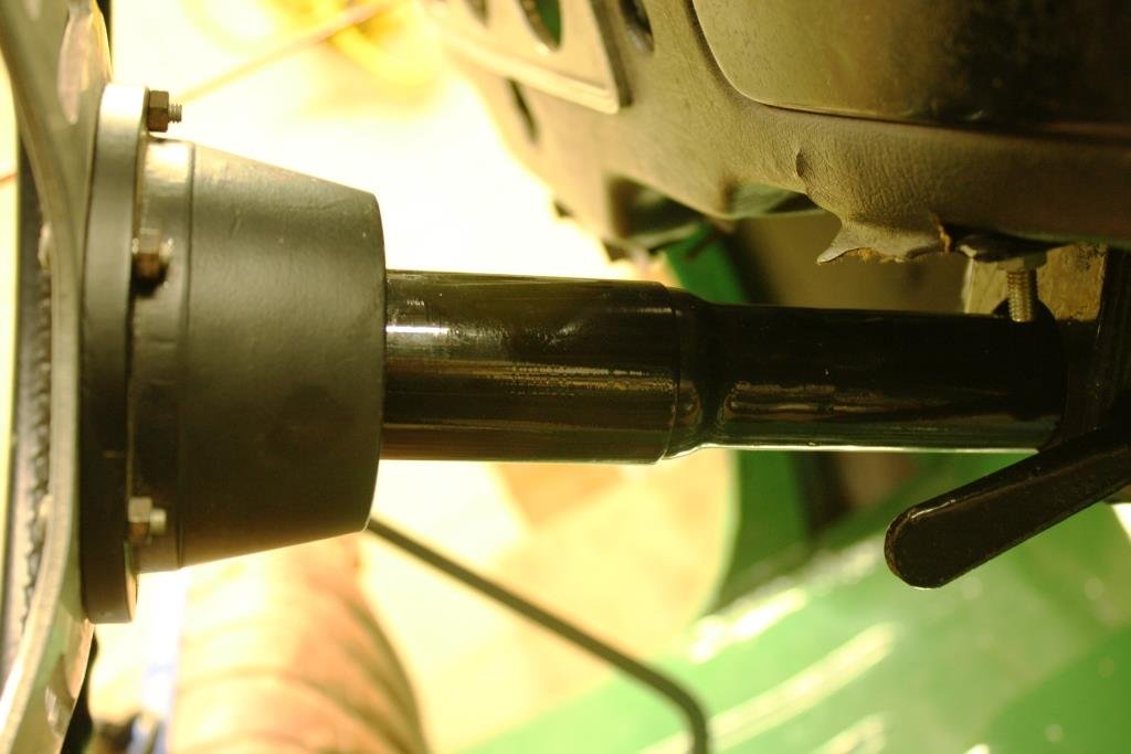
And ended up with this….
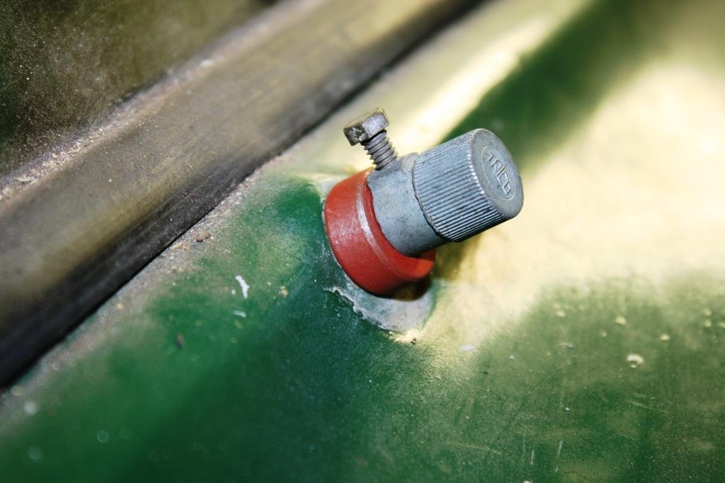
Checked that it was still a good interference fit…..
Three coats of black epoxy enamel and it’s a good result.
-
27
-
- Popular Post
- Popular Post
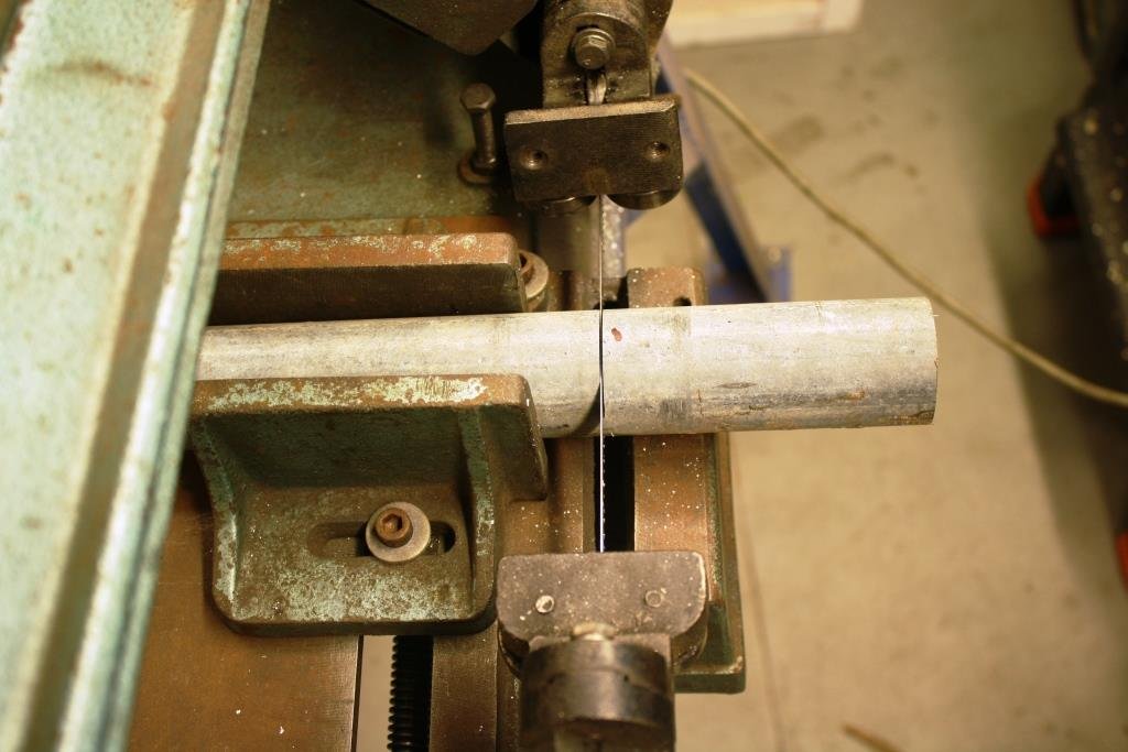
I managed to cut some fancy angles on the band saw without losing any fingers…
Tacked the ‘fancy angle’ bits in place….
And plated the top.
I often use damp rags to keep the heat under control, harking back to my days of welding sheet metal with gas.
Have to say making all these little tack welds and grinding afterwards doesn’t sit well with me (I like big, grunty welds) but it does keep the distortion under control, it’s just not very elegant. Maybe I need a Tig?
Tacked more metal on the sides…
Gave it a tickle with the gas…..
And started stitching it all up.
With everything welded up and still nice and straight it’s time to cut the unused steel out.
Before…
After……
I left the ribs in there for extra strength, looks a bit clunky but only you guys will see it.
Lots of grinding on the floor, on my knees.
(No comments about Mecca being in the other bloody direction please!).
Out with the old standby - CRC rust converter…..
A quick test fit before paint…
Regrettably, and much to Rigamortice’s disgust I stooped to using poo for the first time in this build.
Just a little bit of Newtech to smooth things out (I didn’t want to grind the welds down too far).
Some primer and two coats of ‘insipid green’……..
And it still fits….(phew)……!
-
32
-
 1
1
-
- Popular Post
- Popular Post
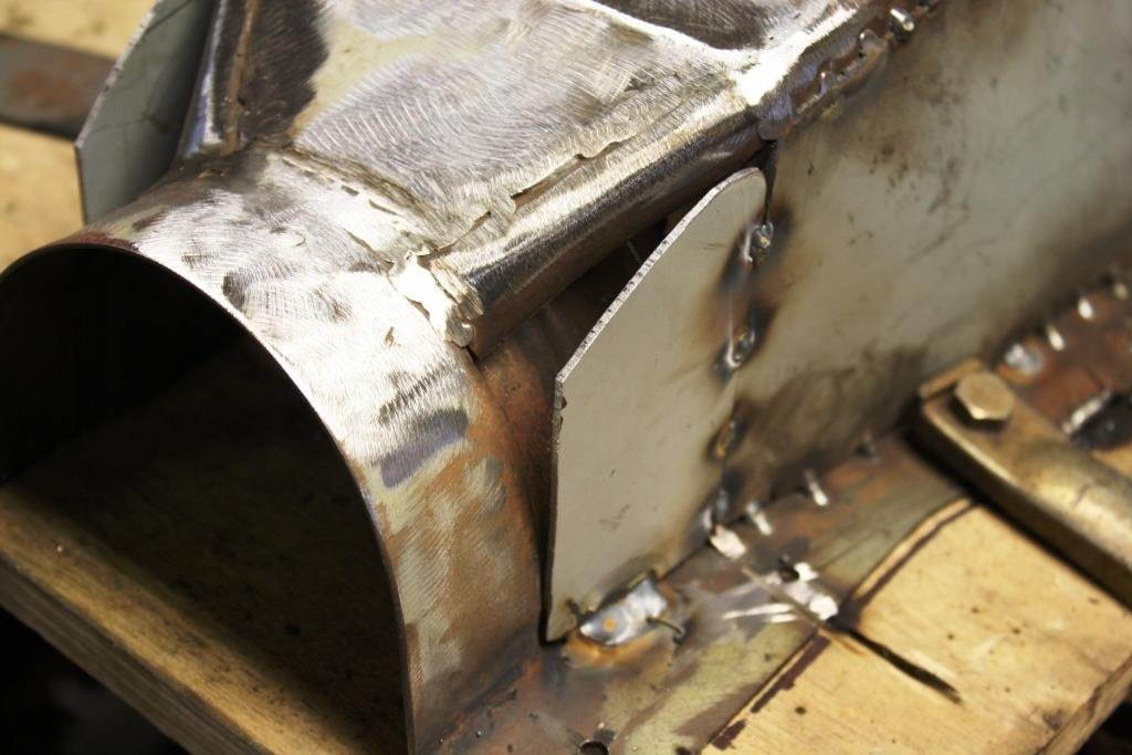
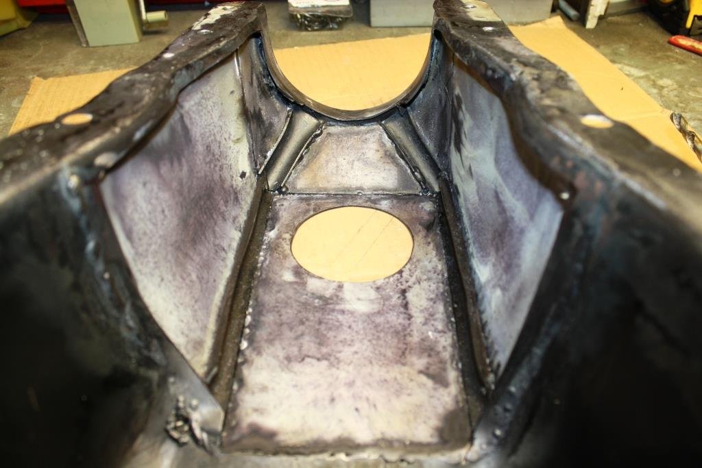
Time to get my butt into gear and finish the gearbox cover.
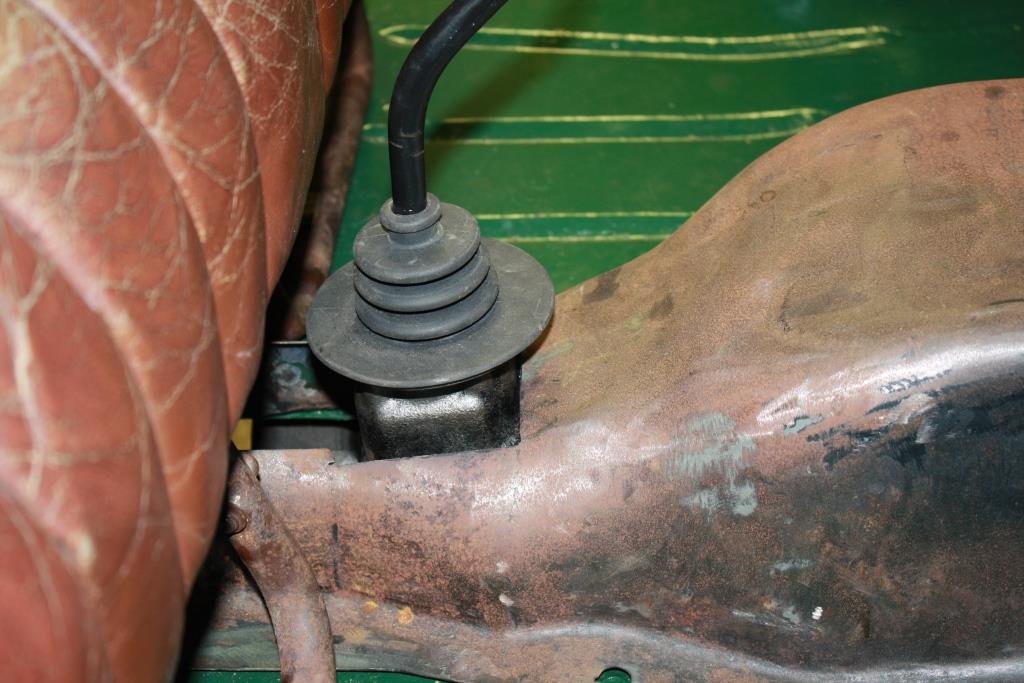
I settled on using the MGB gear lever boot, it looks cool, English, and old-school.
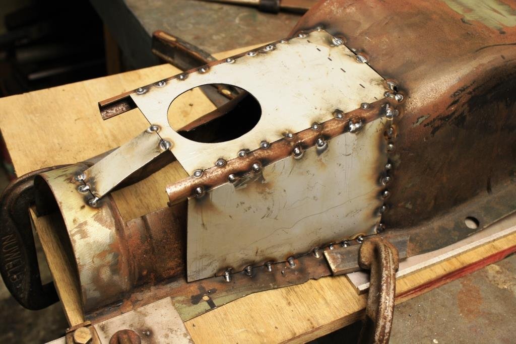
Made the call that the safest way to modify the "trans", (sorry, “non binary”) cover is to not remove any of the original metal until the new steel is welded in.
I cut out a piece of plywood to act as a temporary spacer to give me clearance for the boot.
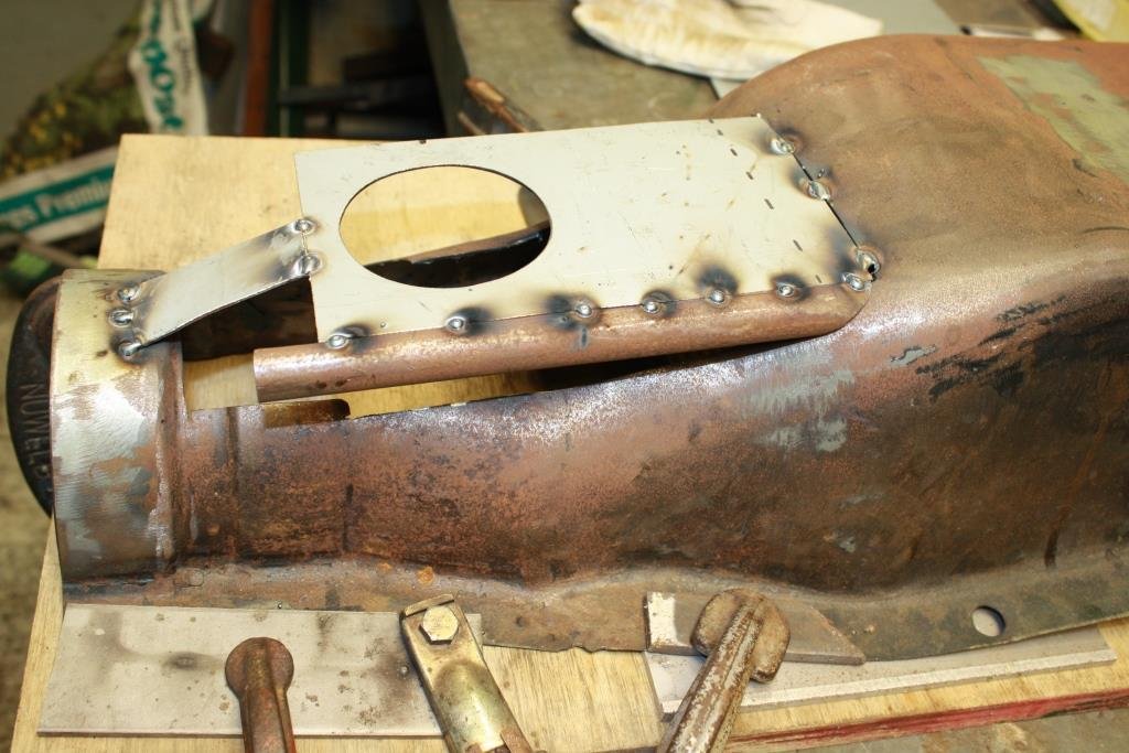
I cut out a piece of 18 gauge Zintex with a hole in it to fit the boot.
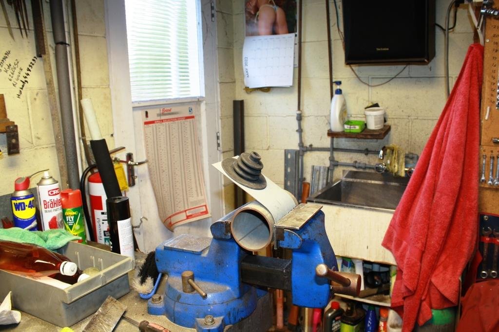
Bent it around an old piece of galv. water pipe…..
….and tacked it in place, lining it up with the plywood spacer.
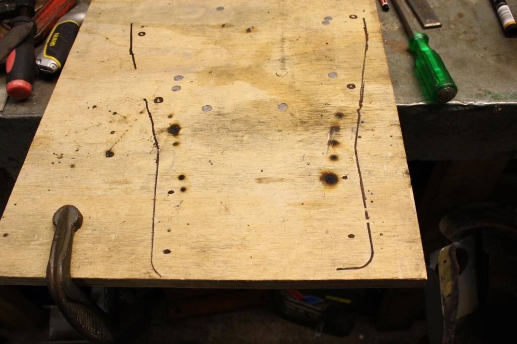
Clamped it all to a thick piece of ply and marked the outline to act at a reference point to keep things straight.
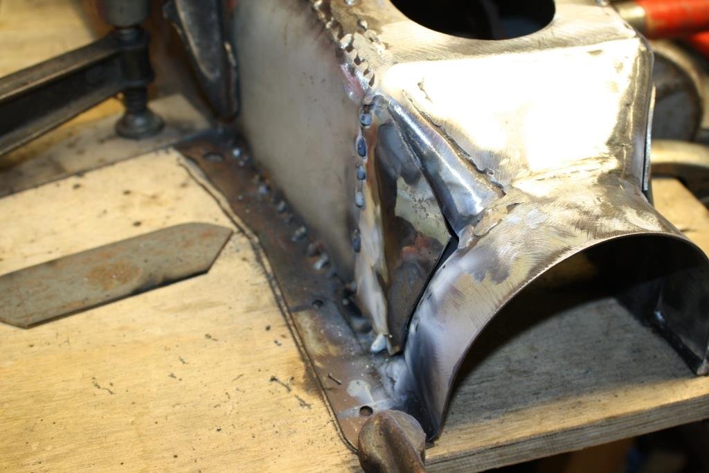
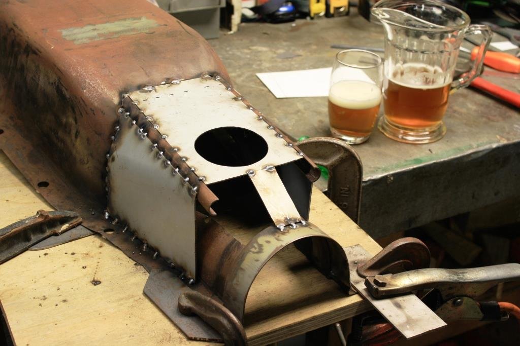
With no sheet metal roller I decided to fabricate the curved corners I needed by slicing up some EWS tube.
Tacked the corners on……..
And added some sheet metal.
I did the same to the other side, followed by a quick check for clearance in the car………
With everything still straight and fitting well I clamped it back onto the ply in the pre-marked position.
Time for “a cleansing ale”.
-
21
-
On 22/08/2023 at 08:48, Nominal said:
It makes the dark work - usually recharged via a solar panel.
I've had to hack in a couple of C-cells on an old helmet.
/Beaten
That makes sense. I have a 10 year old Ultrashade helmet that I'm fond of, (i.e. I'm used to it). If I don't use it for a month or so it a little slow first time I strike an arc.
-
10 hours ago, Nominal said:
Latest LVVTA Newsletter is out
Interesting to see how they dragged up a historic dispute.
Their article then made no reference to the overseas composite experts who submitted evidence?
I suspect that if it had been a T-bucket, (beam axel, no rollover protection, horizontal steering wheel,.... etc.) there would not be an issue.


SR2’s 1947 Vauxhall “Rigamortice” Discussion thread.
in Project Discussion
Posted
Woops! Just did a quick double check on Google - it's actually a front wiper motor.