

Guypie
-
Posts
854 -
Joined
-
Last visited
Posts posted by Guypie
-
-
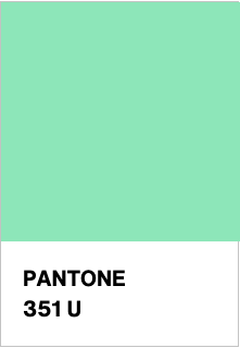
So I asked a bunch of folks to pick a colour from the pantone colour finder and see what the public opinion on the colour selection is.
https://www.pantone.com/hk/en/color-finder
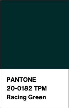
Here are the candidates:

And lastly a classic:
I am going to try put up a poll up if I can figure out how to do that.
Edit: Go to top of page for the poll
disclaimer: veto power is held by the frame builder, I reserve the right to change my mind fi you all vote for the ugliest colour
-
 1
1
-
-
- Popular Post
- Popular Post
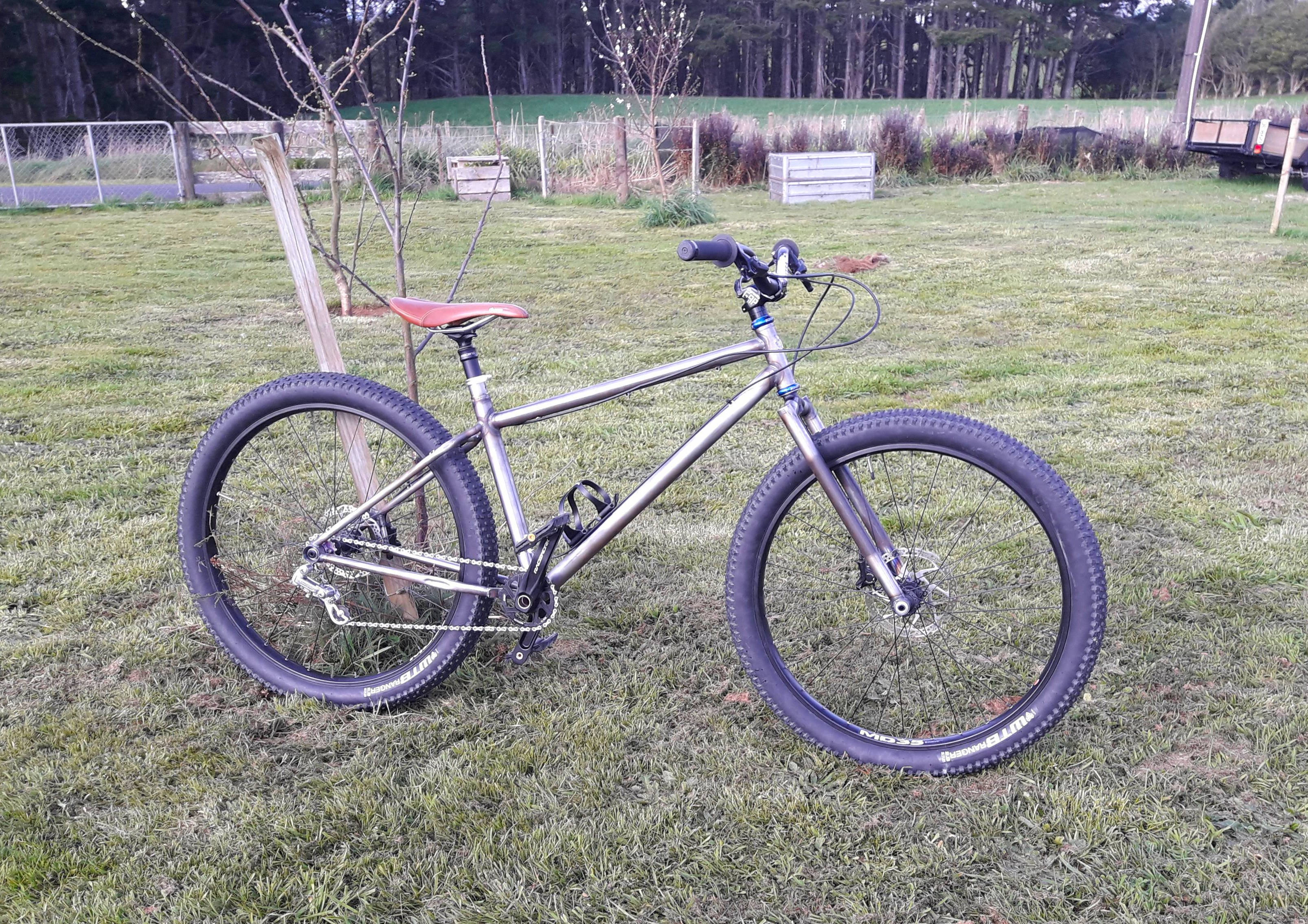
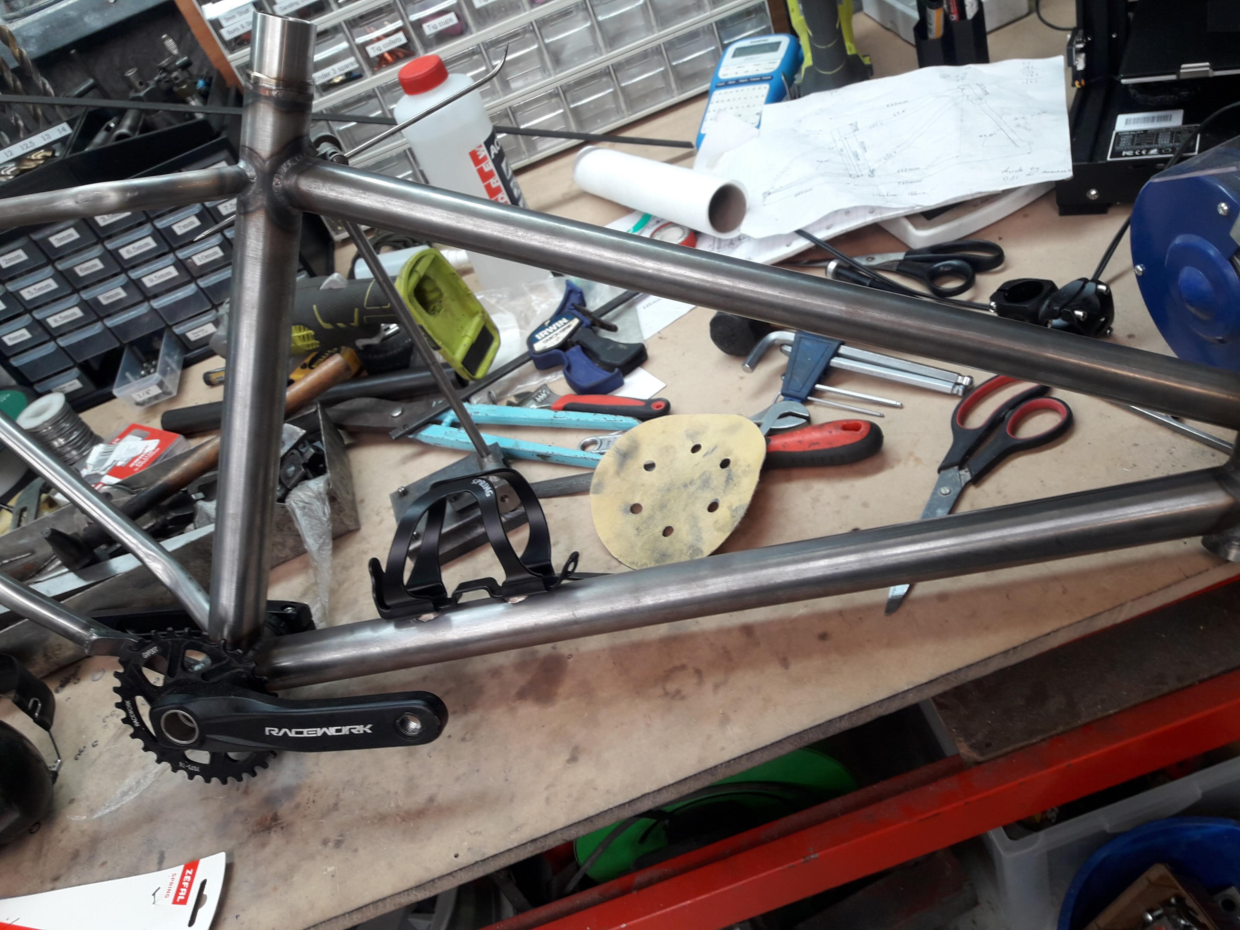
At this point I had enough bits and pieces to assemble the bike and take it for a ride around the yard. Albeit with only one brake, a slipping singlespeed drivetrain and the seatpost at maximum highpost position. The latter issue was solved with a sanding drum on the dremel to bring the tight spot down to size then I was able to get full insertion.
Of the seatpost. I know what you were thinking

I'm pretty happy with that. Took it for a hoon around the yard and did some jumps and the forks didn't snap or anything silly. The high offset forks mean that the front end loved to dart into corners, but taking it up to speed down the road it doesn't feel unstable and seems to behave itself well. The handlebars will be getting replaced with some wider bars (780mm) high rise bars. That will help me to do more of an apples to apples comparison with the geometry in relation to my other mountain bikes since I am not used to the narrower bars that it has at the moment. In terms of playfulness with the longer chainstay length it is definitely more difficult to get on the back wheel, will have to see how it is on the trail as that is always a bit different to mucking around on the flat.
Next on the agenda is painting since all the other stuff has been finalised now.
-
14
-
- Popular Post
- Popular Post
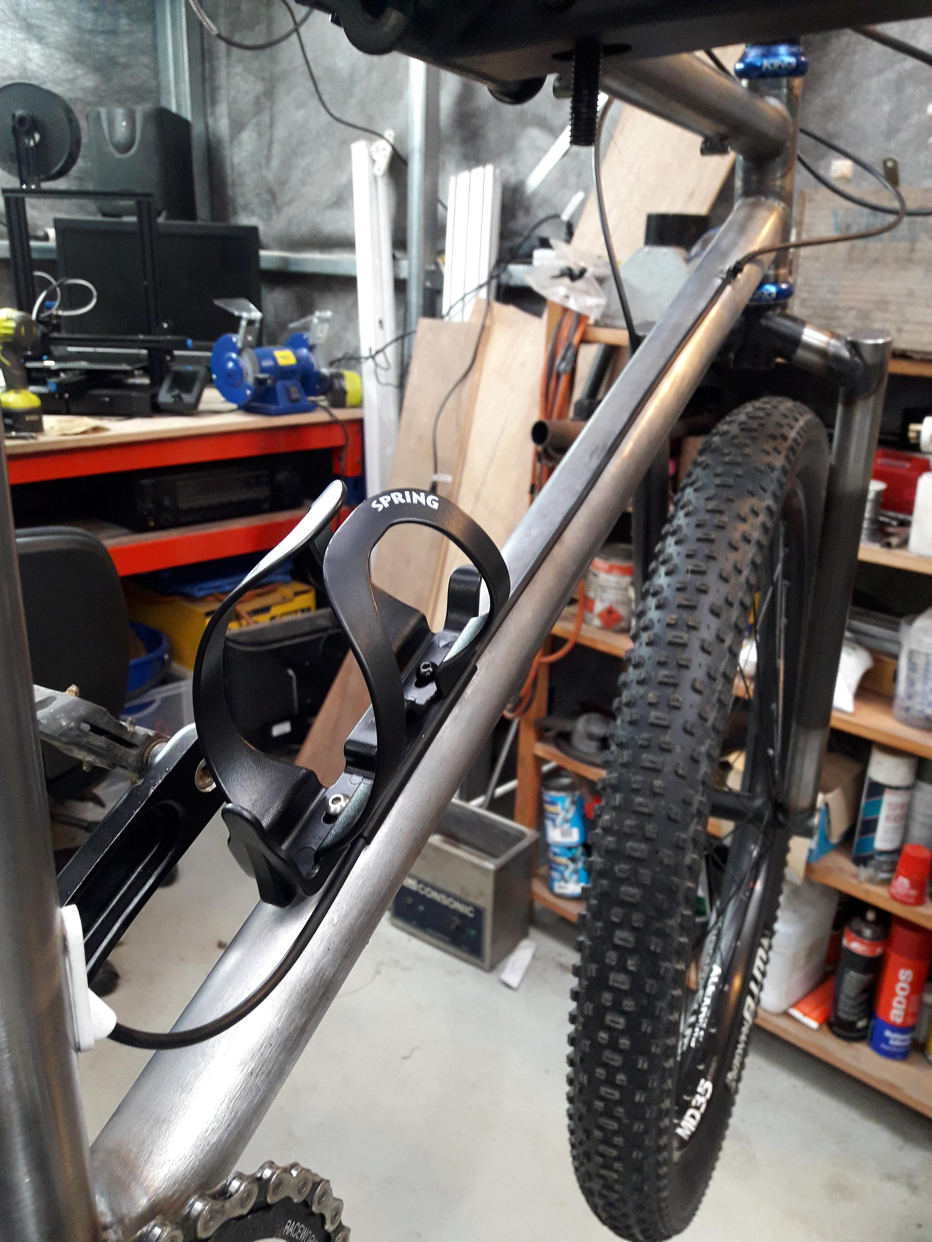
I also printed a cable guide that lives under the drink bottle holder like so:
And I also put a cable tie guide further up the tube then test routed the cable
Works like a dream!
-
11
-
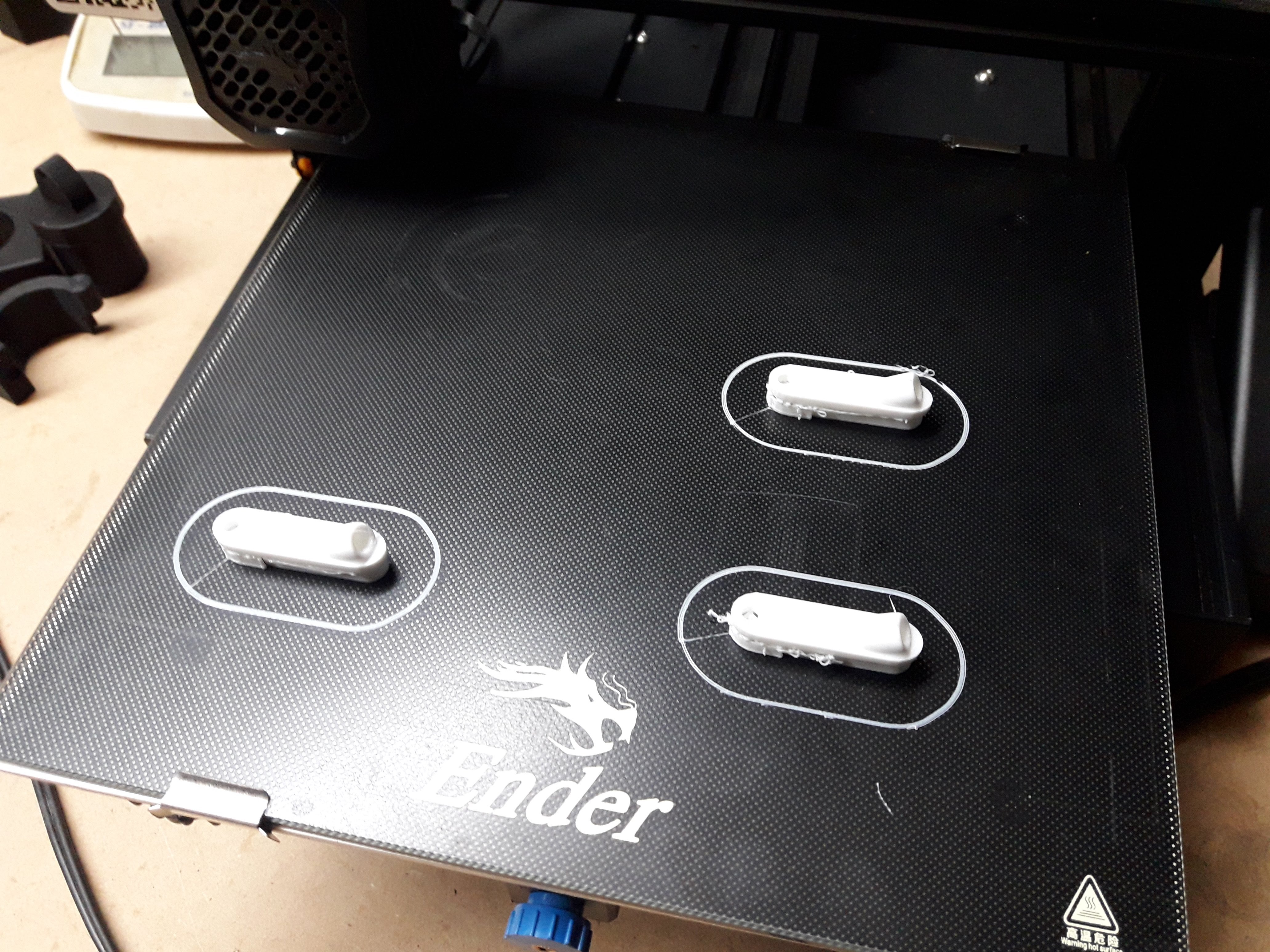
Annoyingly I was out of black filament but I had some ancient white stuff lying around that had gone all brittle. Apparently if you pop it in the oven at 50*c for a hour it fixes it, but out oven thermostat is broken and only goes full noise. So I hit it with the heat gun for a couple of minutes being careful not to overheat it and gave it a nudge.
They came out a bit ugly but at least it made it through the extruder. Will have to get some more filament after lockdown.
-
3
-
-
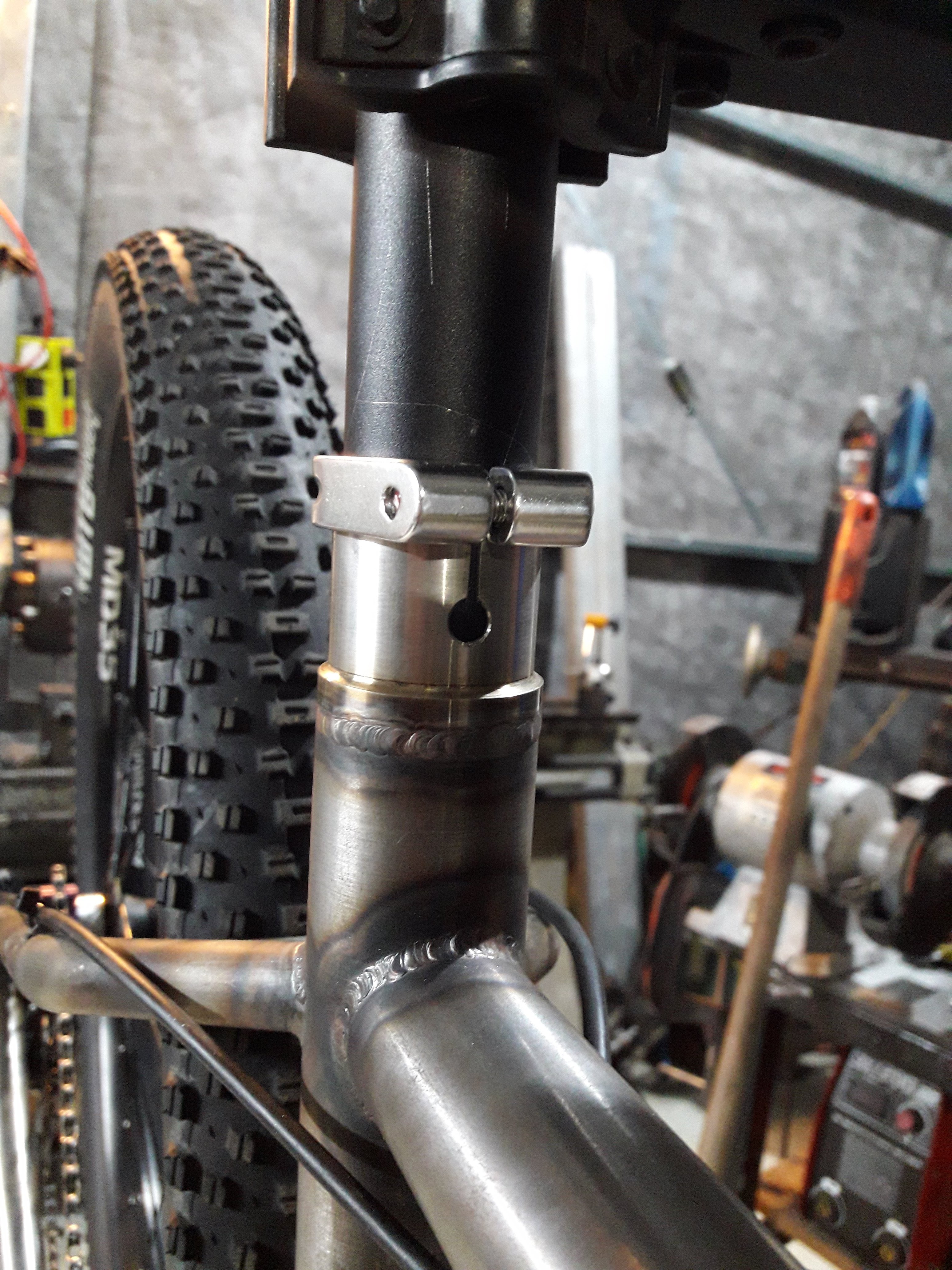
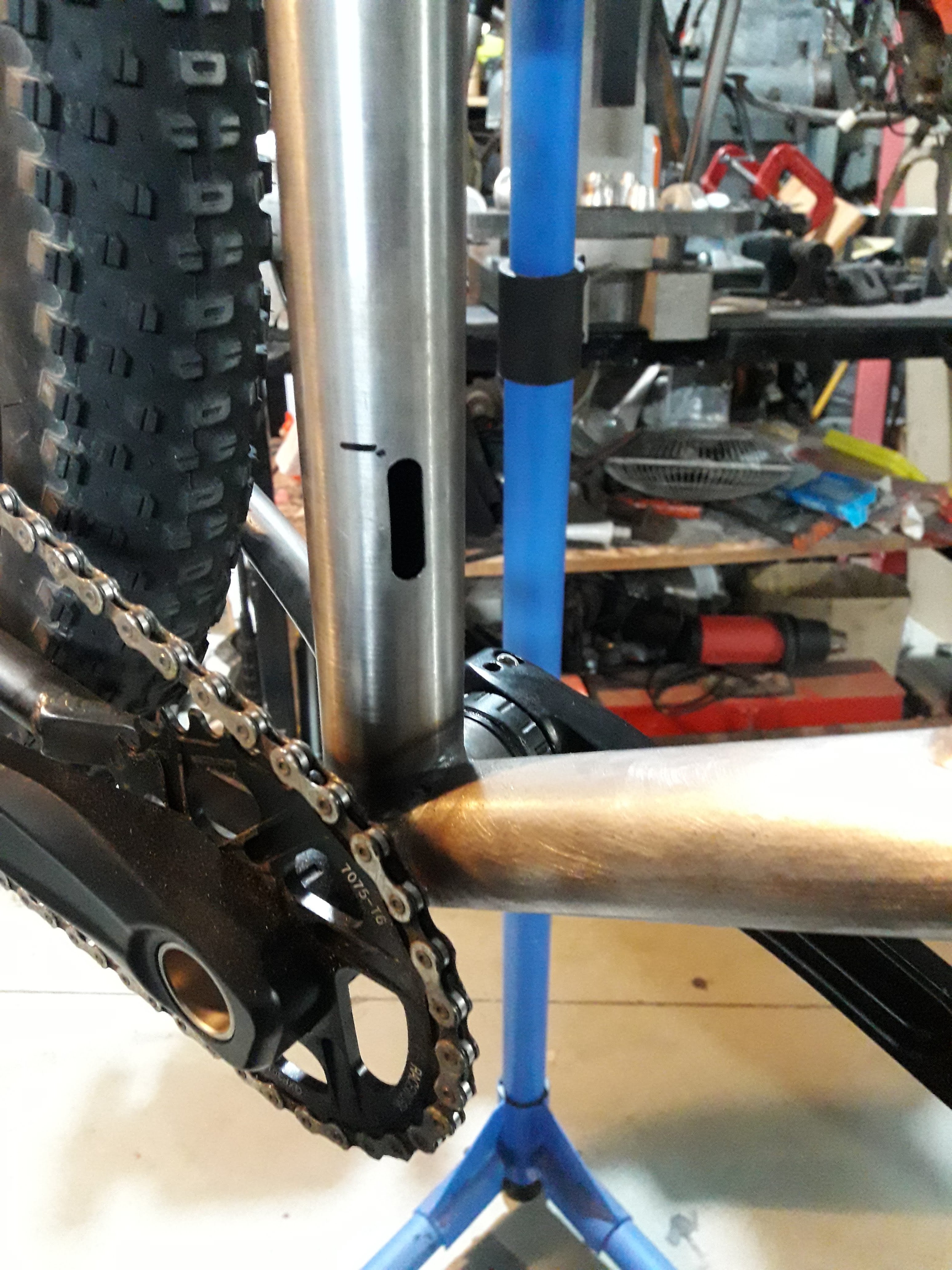
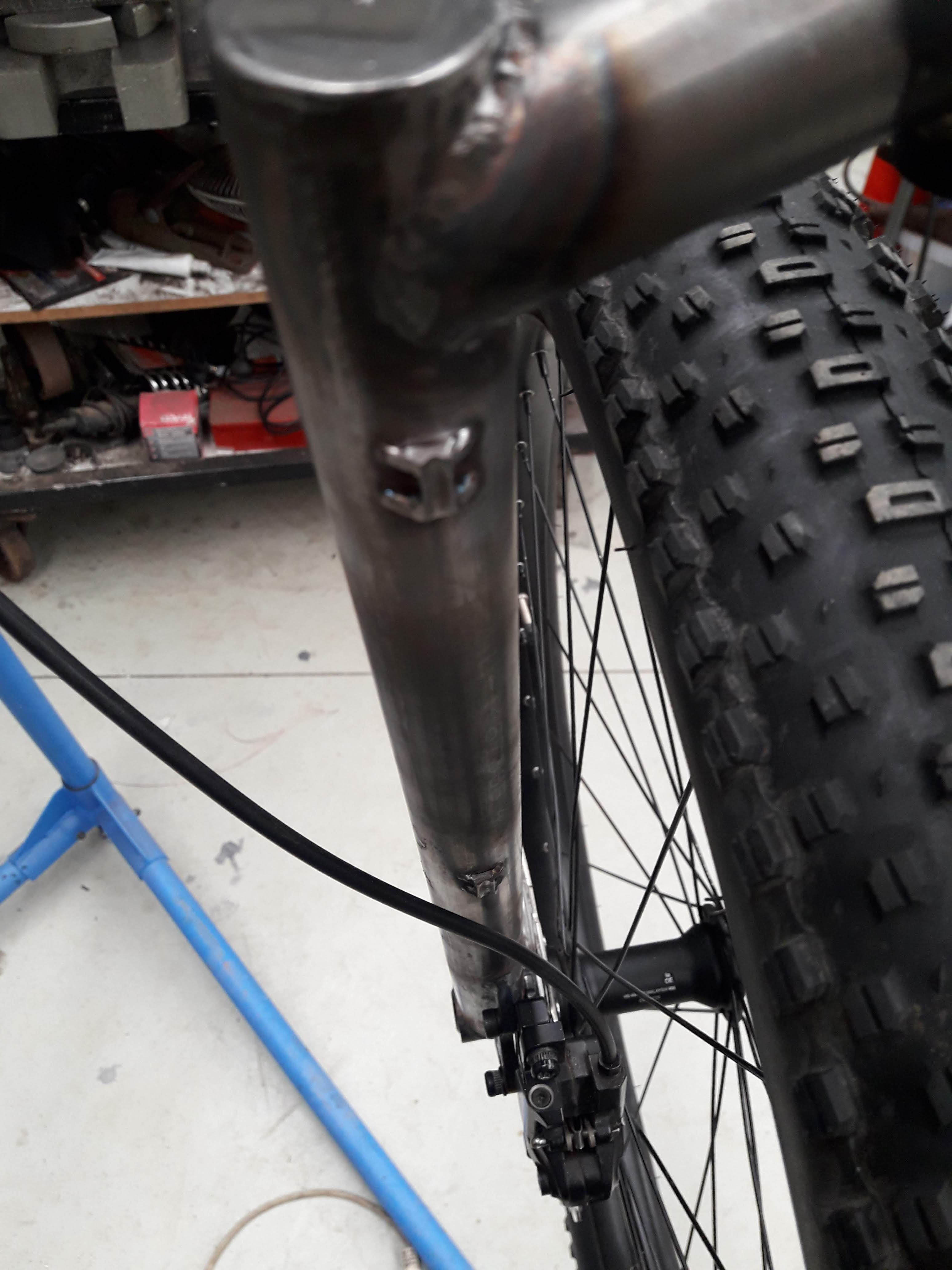
It is mildly terrifying taking an angle grinder and drill to the frame I have spent many hours making. But thats what you have to do to slot the seat tube and fit the cable routing for the dropper post.
I started with marking out and drilling the hole, then moved between angle grinder, hacksaw and file to make the slot and tidy it all up. It turned out pretty well, very pleased with the outcome
I went with the front seat slot which I recon looks a bit uglier because if you ever ride in the rain and mud it decreases the chance on filth getting down your seat tube and seizing the post into the frame. Shouldn't be an issue anyway because of the stainless insert, but better safe than sorry.
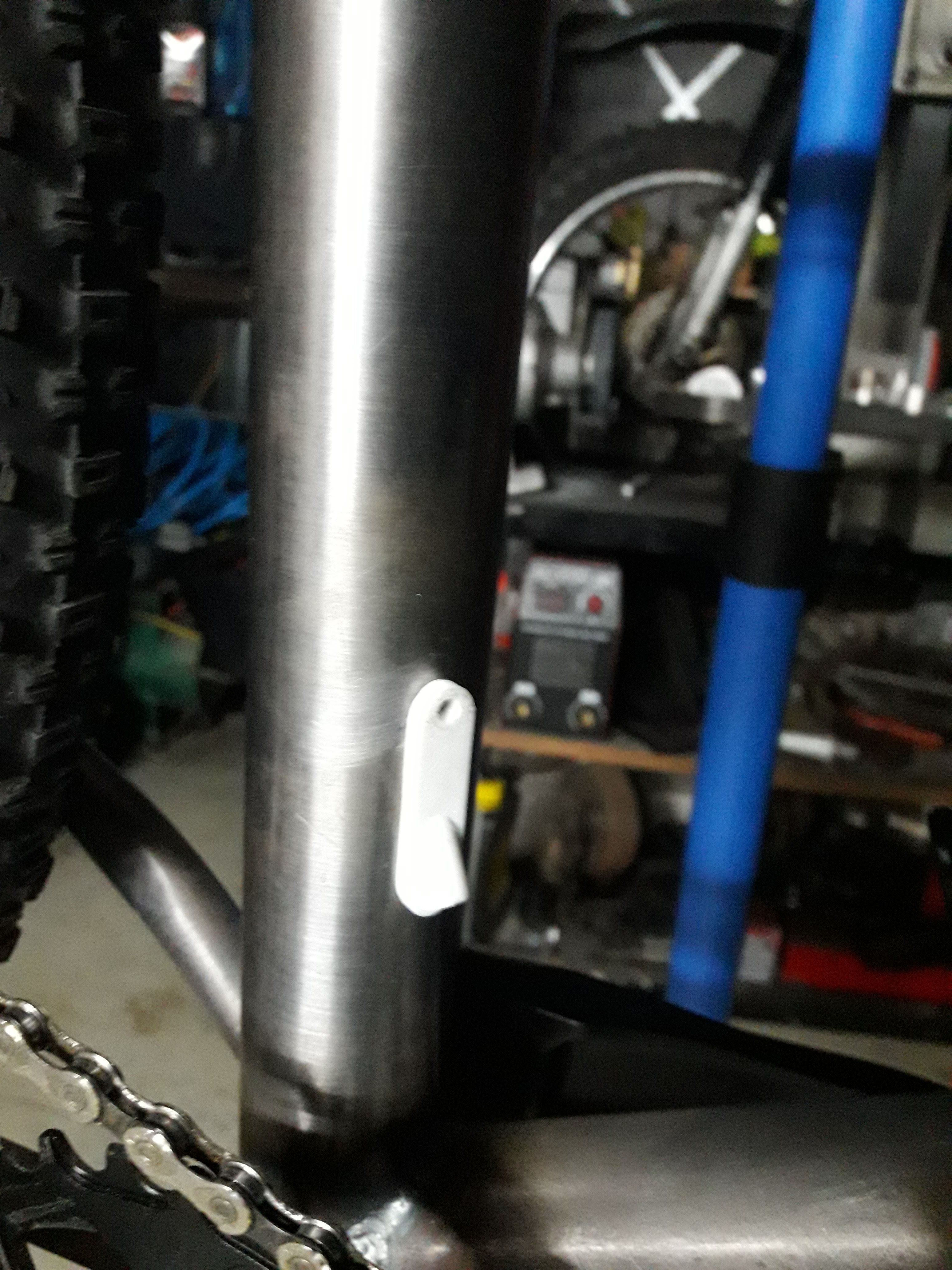
Next up I downloaded a 3d model for a grommet for the dropper post cable routing. It measured 8mm wide and 21mm long, so I drew a vertical line on the seat tube and marked out 21mm and drilled 8mm holes at either end and cut a slot with the dremel.
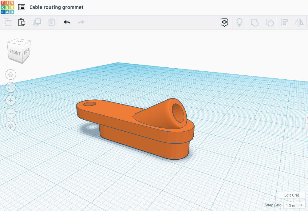
Some of you are probably already seeing the problem with this, I potato brained it up and made a 29mm long slot so the downloaded insert was too short. So I did what I probably should have from the beginning and drew my own grommet to suit my oversized grommet hole (that would be a good insult).
The plan with the hole at the top is that I will get a rivnut setter and put a m4 insert in with a nice little cap screw to hold it in place. Press fit works too, but I think this will be a little nicer.
-
6
-
-
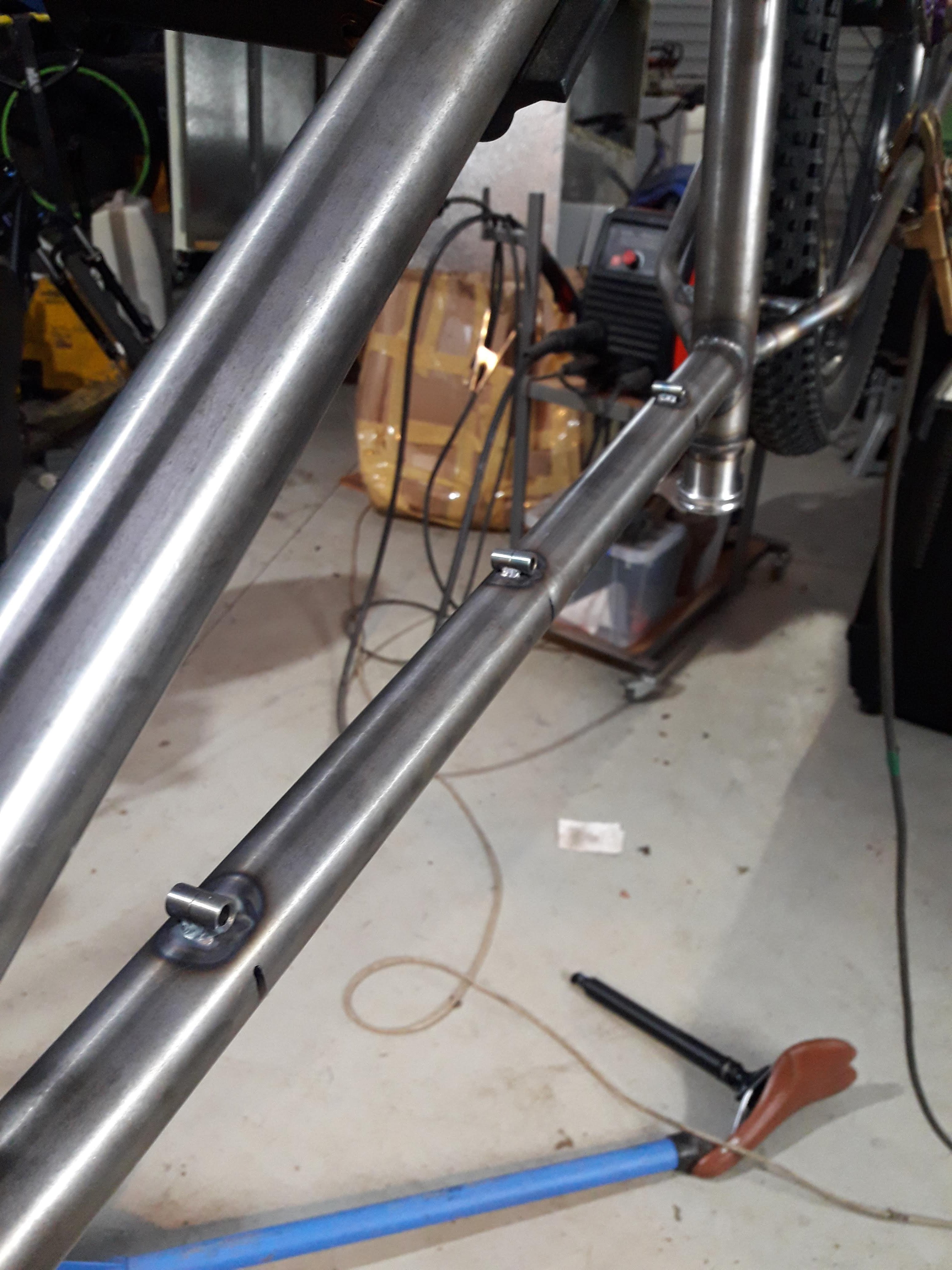
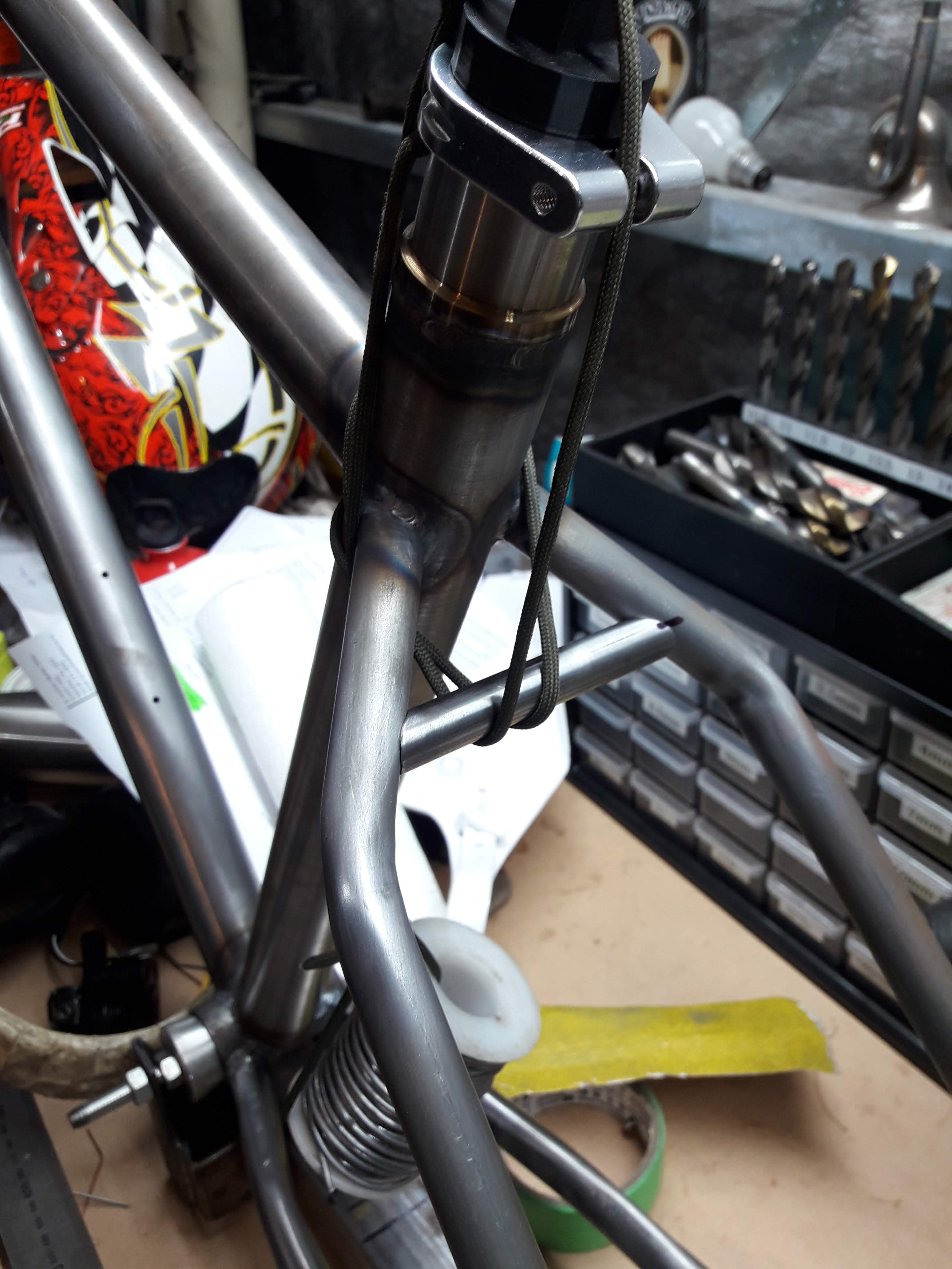
There's not much left to go! First up was a bit more cable routing, I made a few more cable tie hose guides and popped them on for the derailleur and the front brake hose
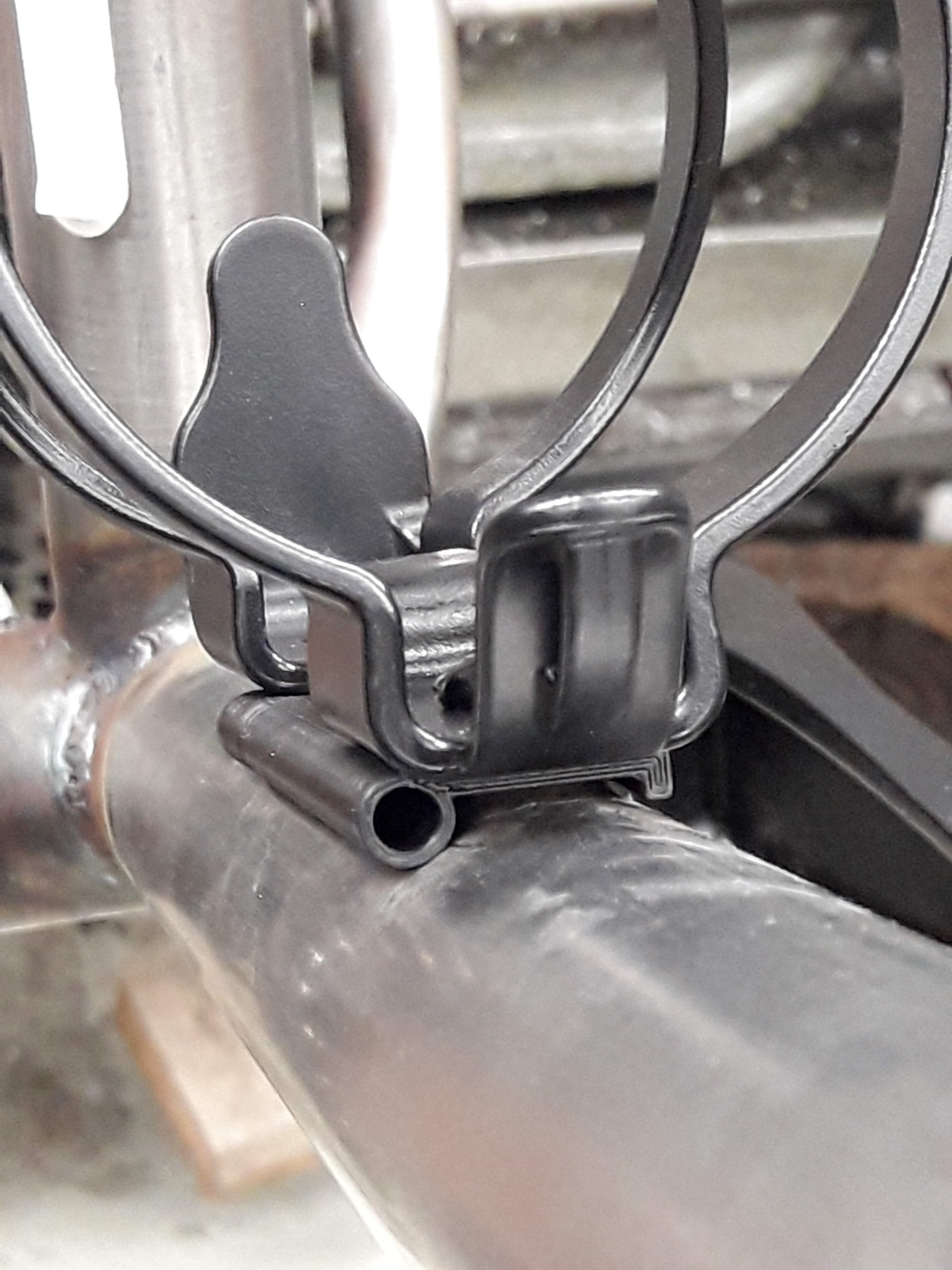
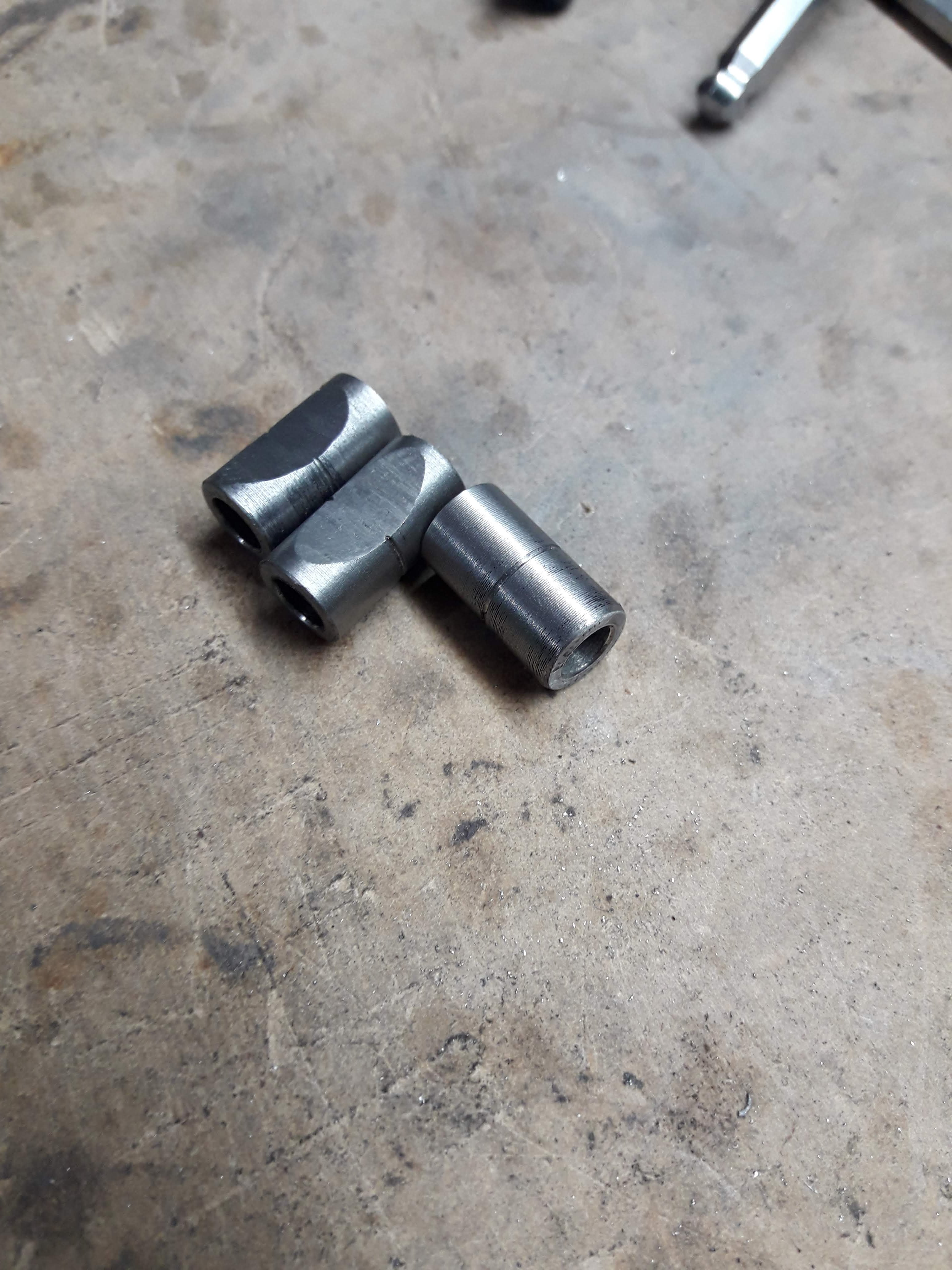
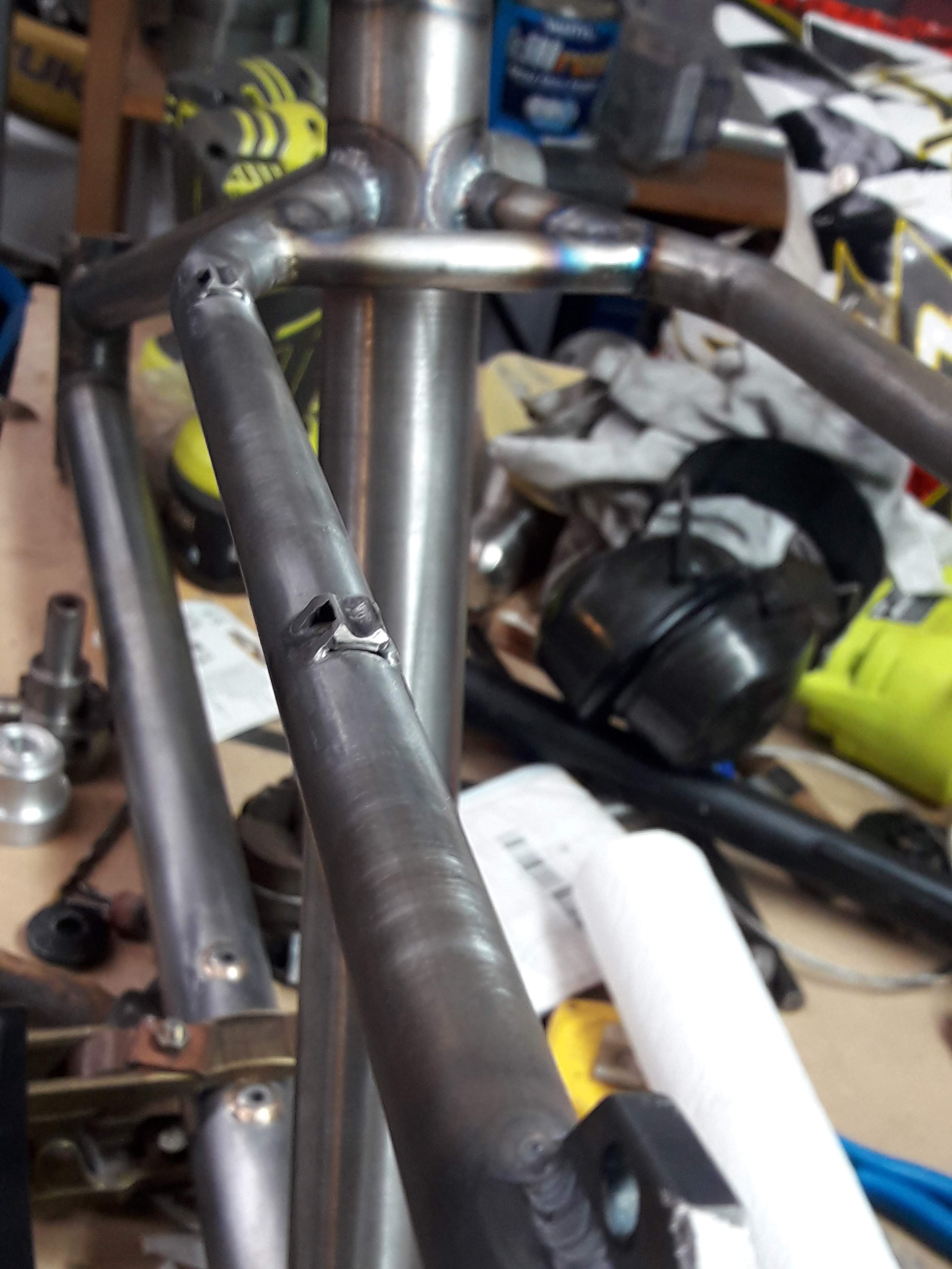
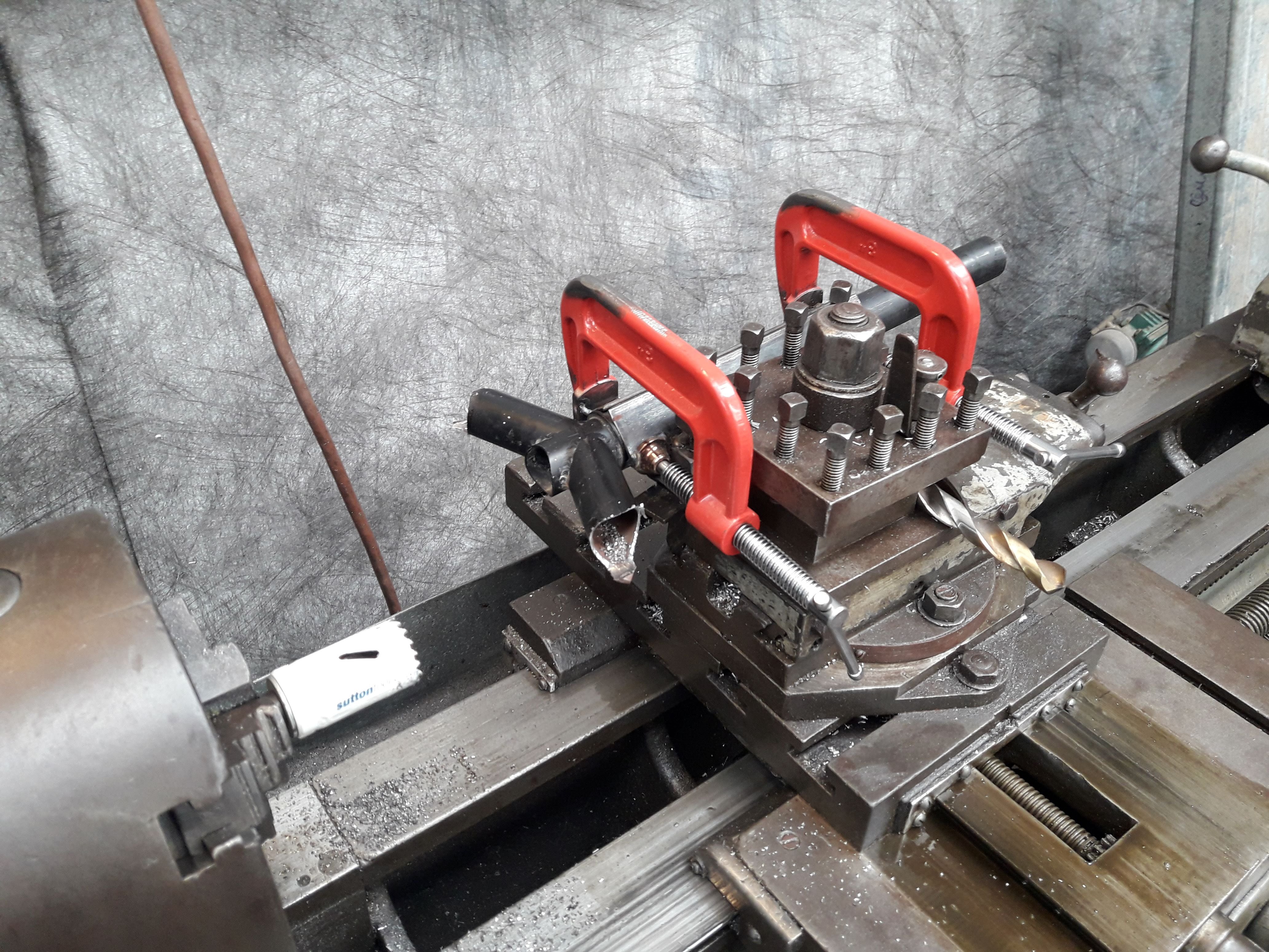
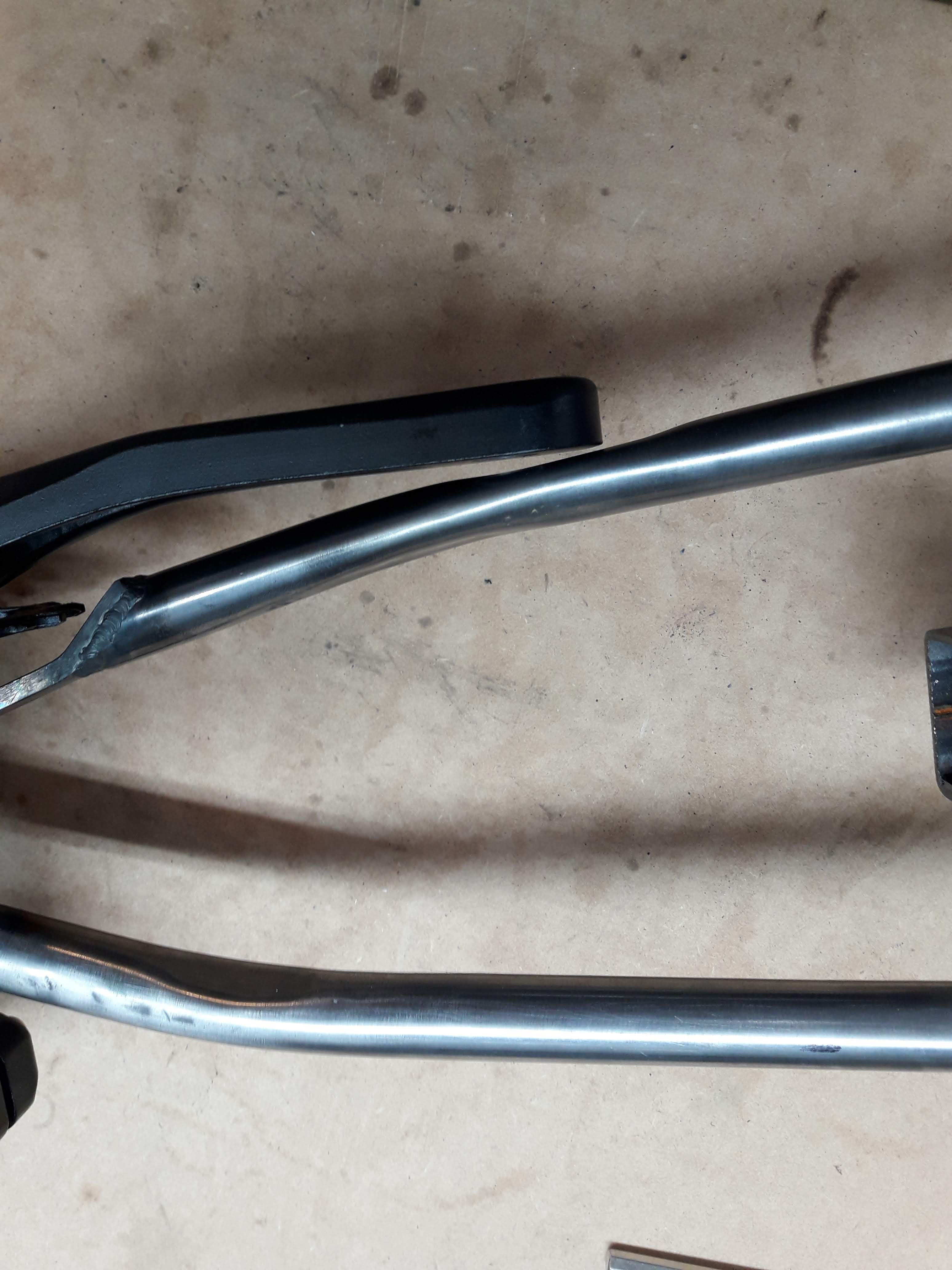
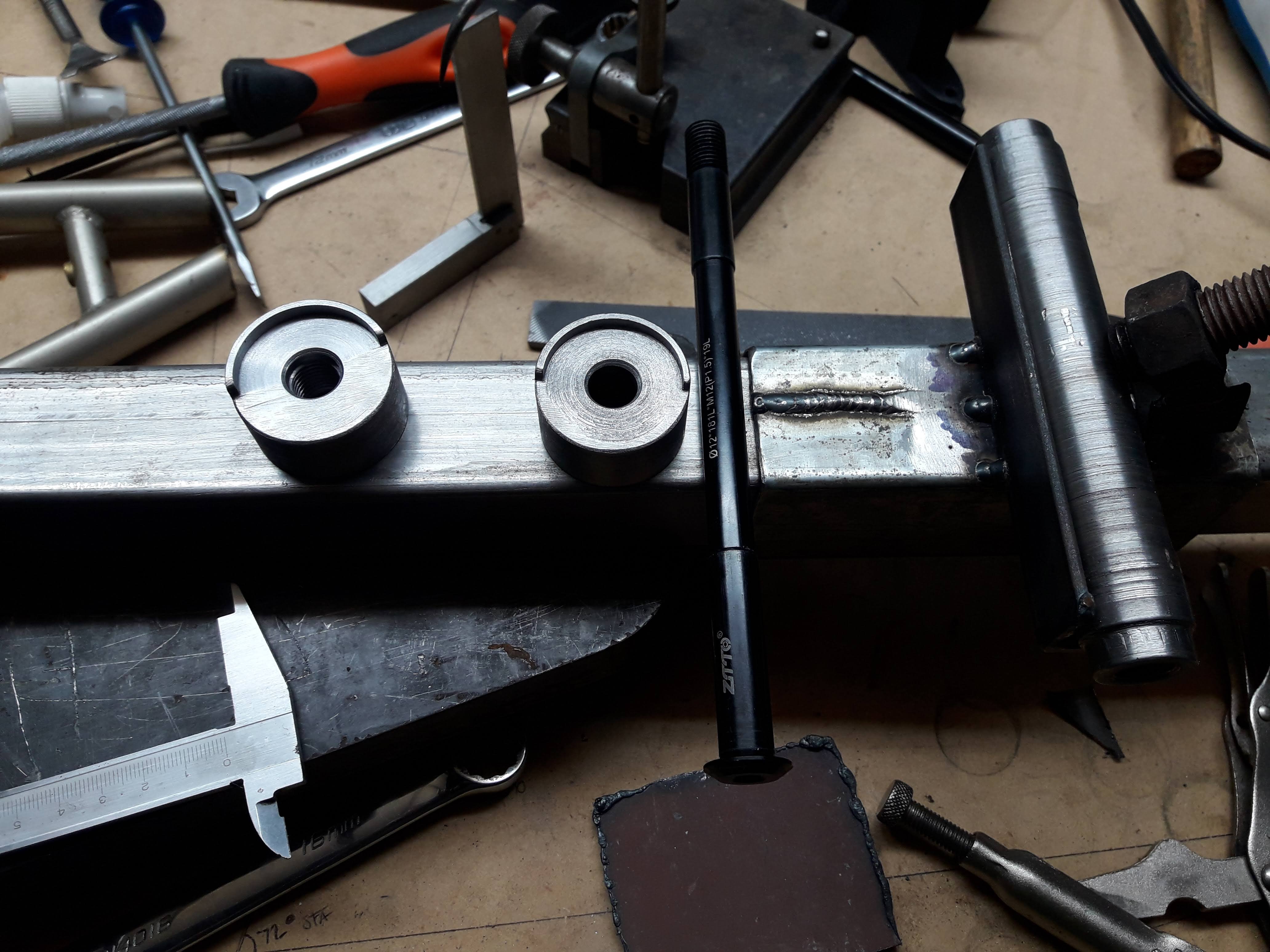
For the routing from the front triangle to the rear I needed to come up with some other solution because the cable tie ones like in the photos above take me more than an hour per item. If I set up in more of a production line I could probably bring it down a bit but I didn't feel like making another 6 of them. So I had a think about what would be easy to make on the lathe and would look fairly tidy and came up with these:
Weld on the the underside of the tube. Pass the cable tie through, around the far side cable and back through and tighten down on the near side cable.
I forgot to take a picture of them in action, they aren't as tidy as the proper version, but they look fine in practice. Next time around I will put bottle bosses on the underside of the top tube before welding up the front triangle as that would have been my preferred method, but there wasn't clearance to fit a drill post welding. From there you can get stuff like this: https://www.paragonmachineworks.com/catalog/product/view/id/3578/s/aluminum-double-cable-clamp-choose-style/category/77/
-
3
-
 1
1
-
-
- Popular Post
- Popular Post
And here's the cable guides in action:
I also glued the headtube badge in place with some araldite. Its stainless so I will either mask it or sand the paint off it after painting to make it pop
-
11
-
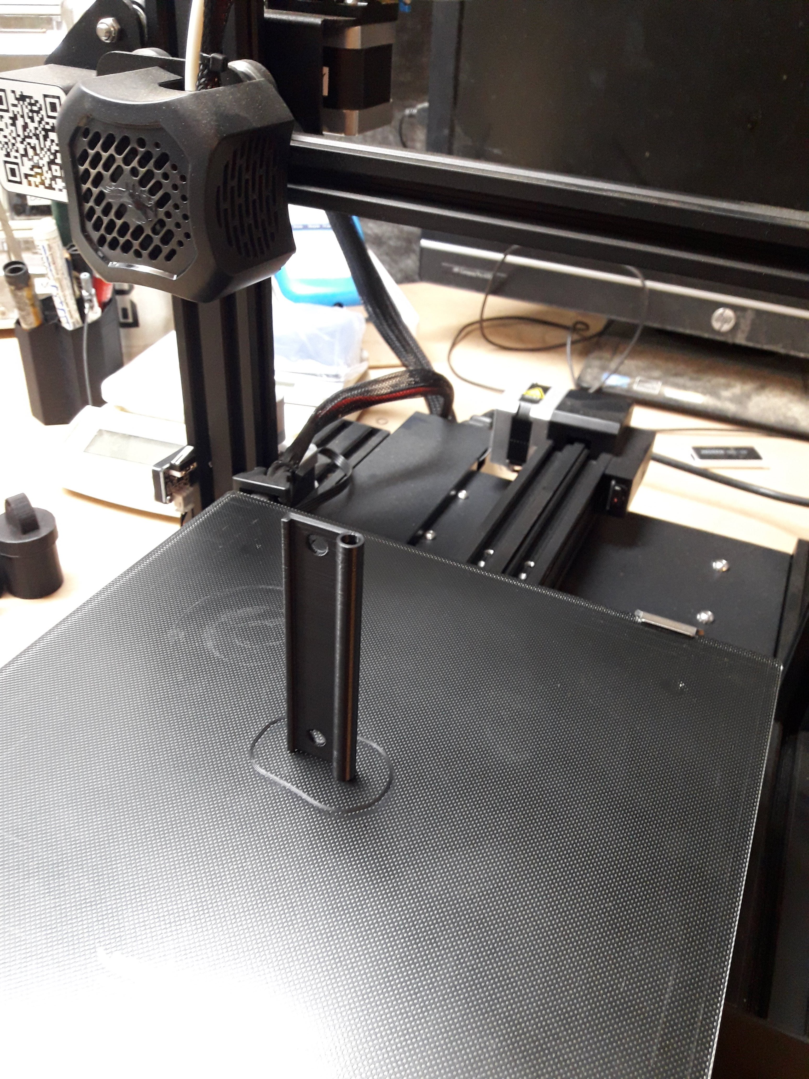
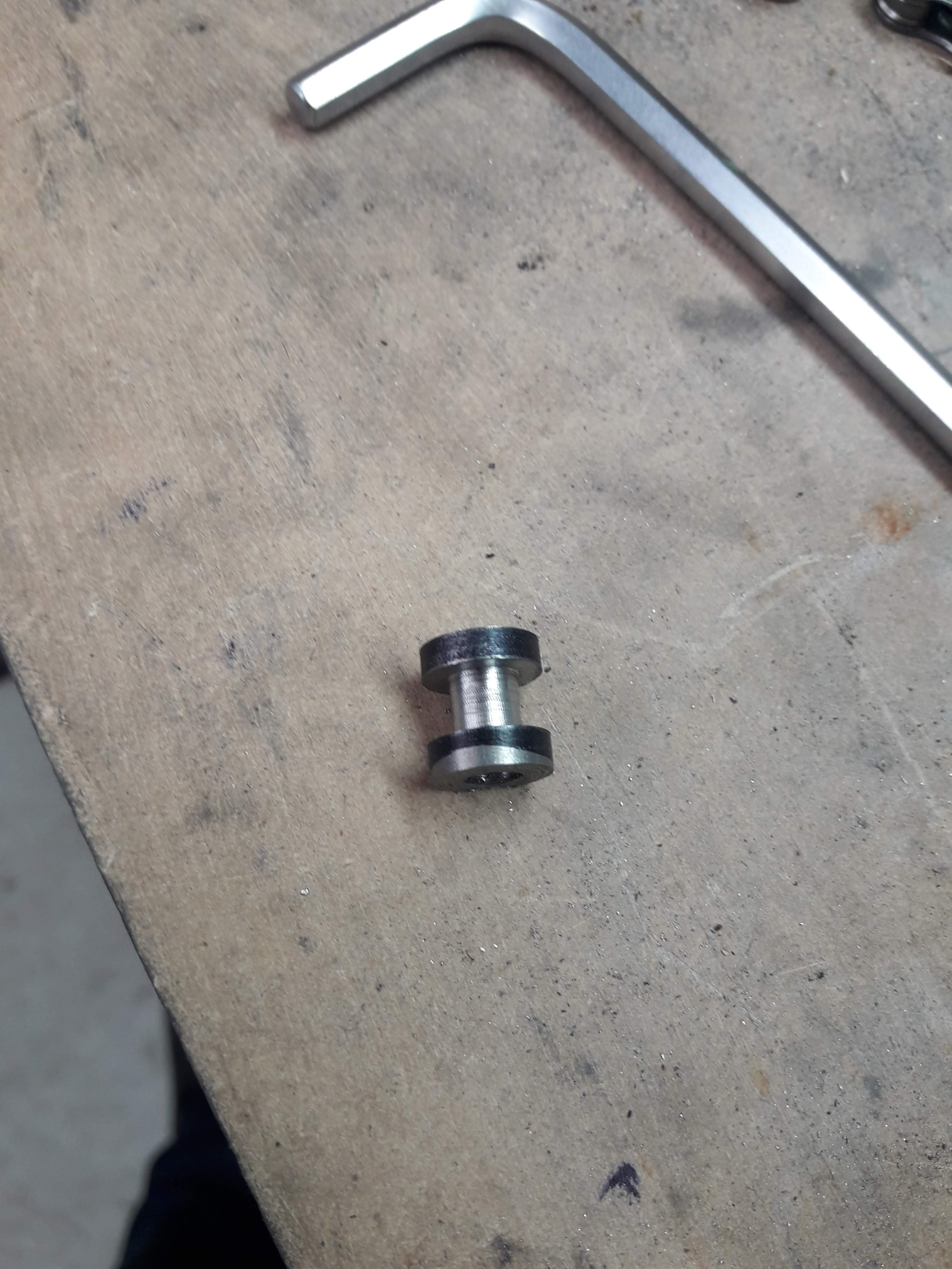
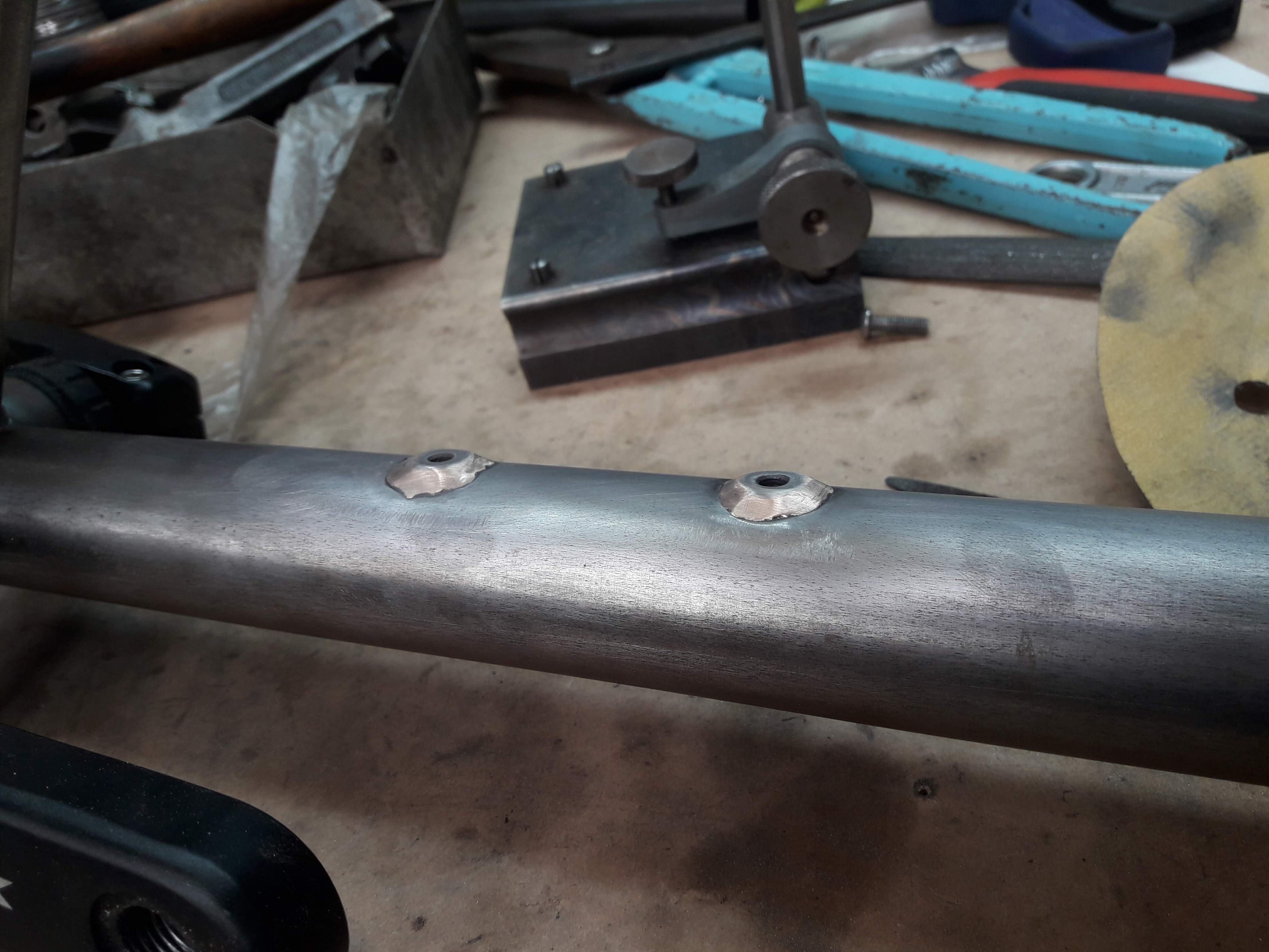
So this is about when lockdown happened. I was contemplating buying cable guides/ braze ons or whatever, but never got around to it and now I have plenty of time on my hands and no cable guides. So I had a look at the general design of the cable tie type hose guides and tried to to think of how I could make something like that using the lathe and not much else.
I started off by making a spool/cotton reel shape with a 5mm hole through the centre like this:
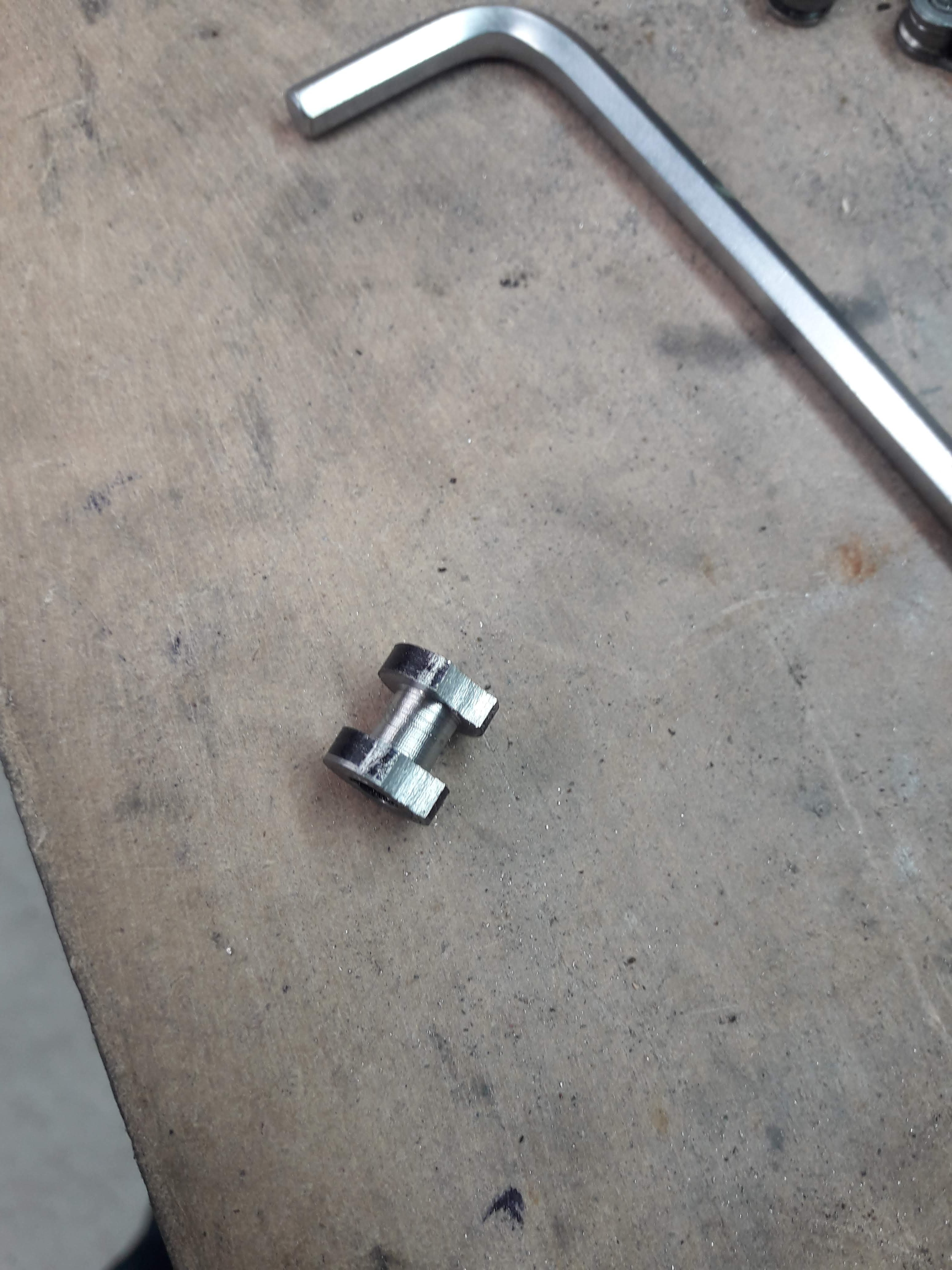
and then filed a mitre into the rim with a round file:
And then cut out with grinder or hacksaw. I found grinder made for less cleanup work afterwards
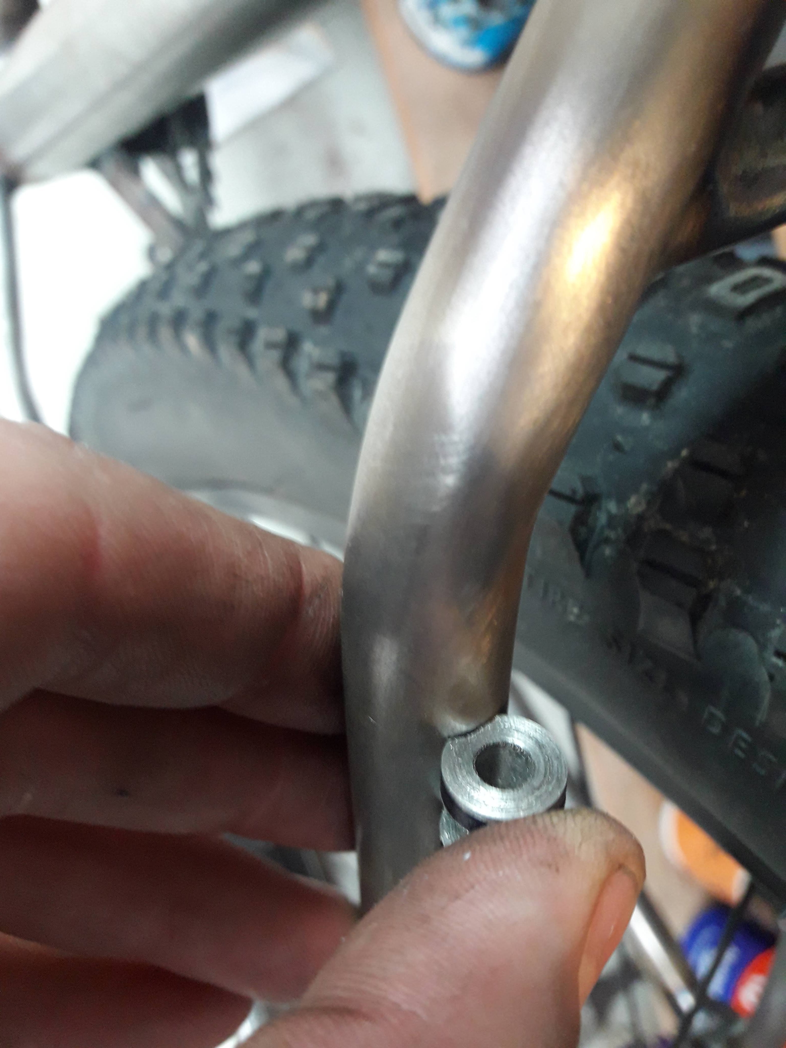
First and second guides in place:
These 2 are a little on the low side and will probably end up with the paint underneath them rubbed off when the frame is done but most of the other cable guides I have put on have adequate clearance
-
7
-
-
2 hours ago, Shakotom said:
Yeah am thinking about it if I find a cheap enough donor bike
Once lockdown is over you can bring it down and we can tig it up and go for a full rigid spin up Pirongia.
1 hour ago, Transom said:Nice build very inspiring
If you can’t tweak your brake mounts to perfection then decent bike shops have disc brake mount facing tools and shouldn’t charge a lot to do it - I have bent the rear disc caliper mount on my steel dh bike a few times and just tweaked it back into alignment
Thats good to know!
-
1
-
-
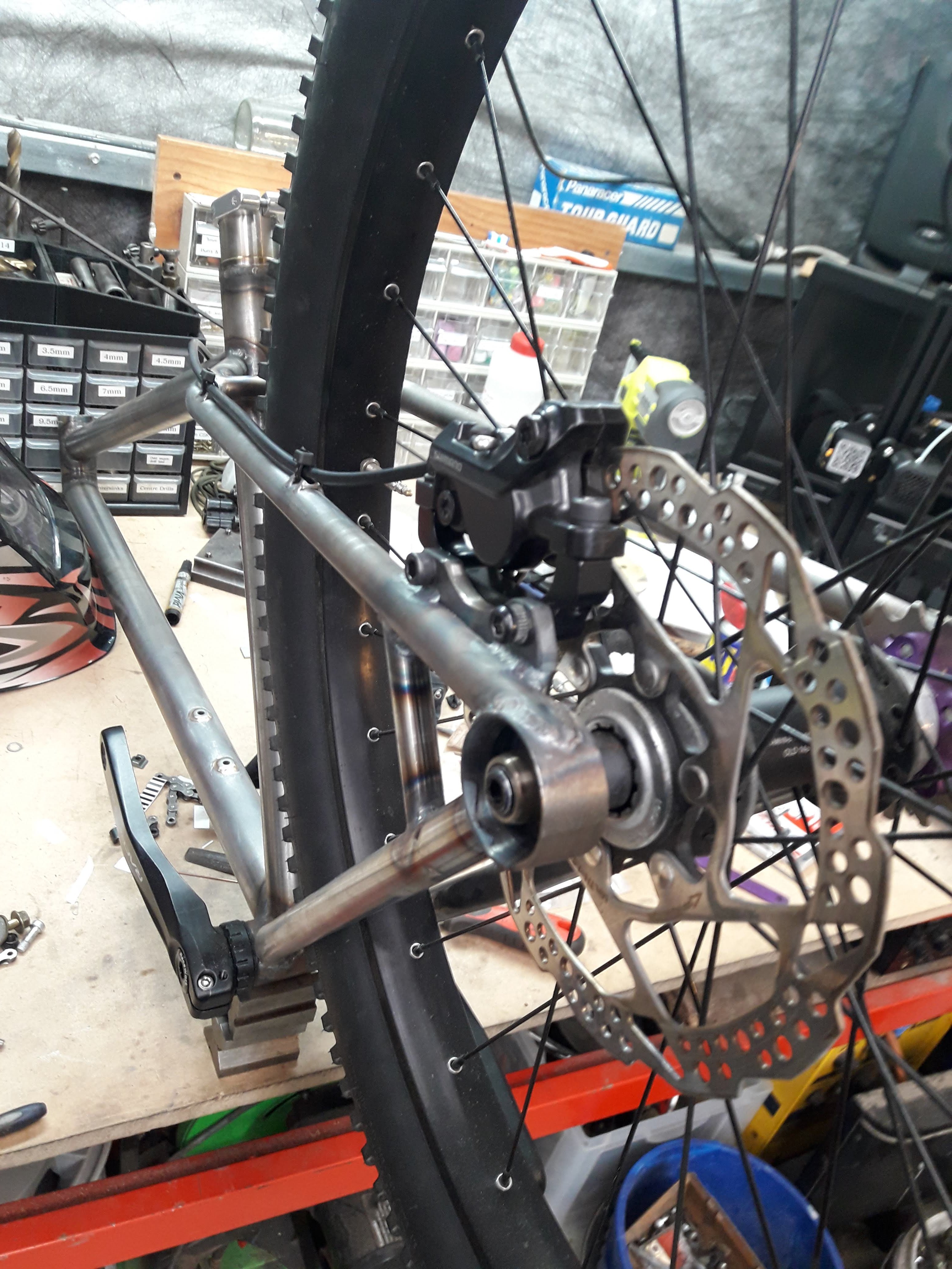
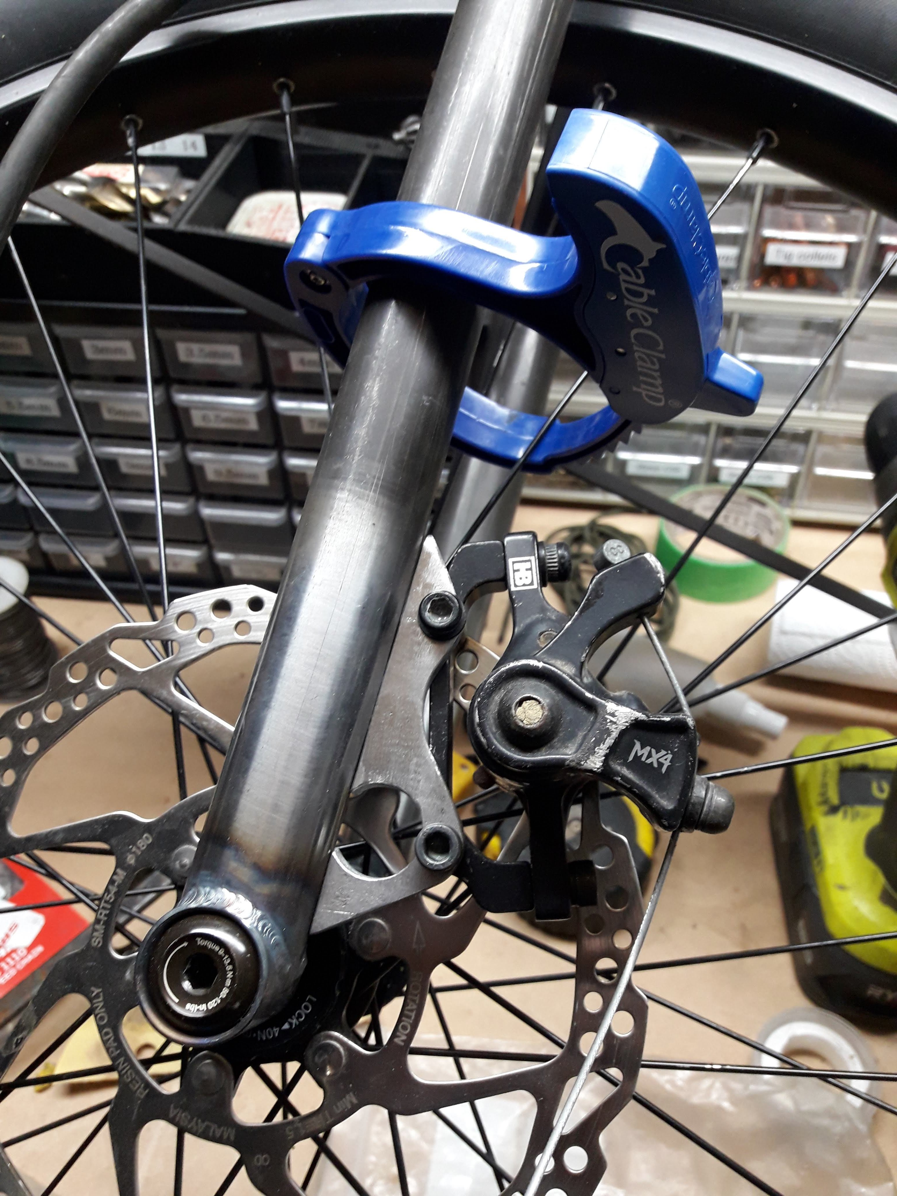
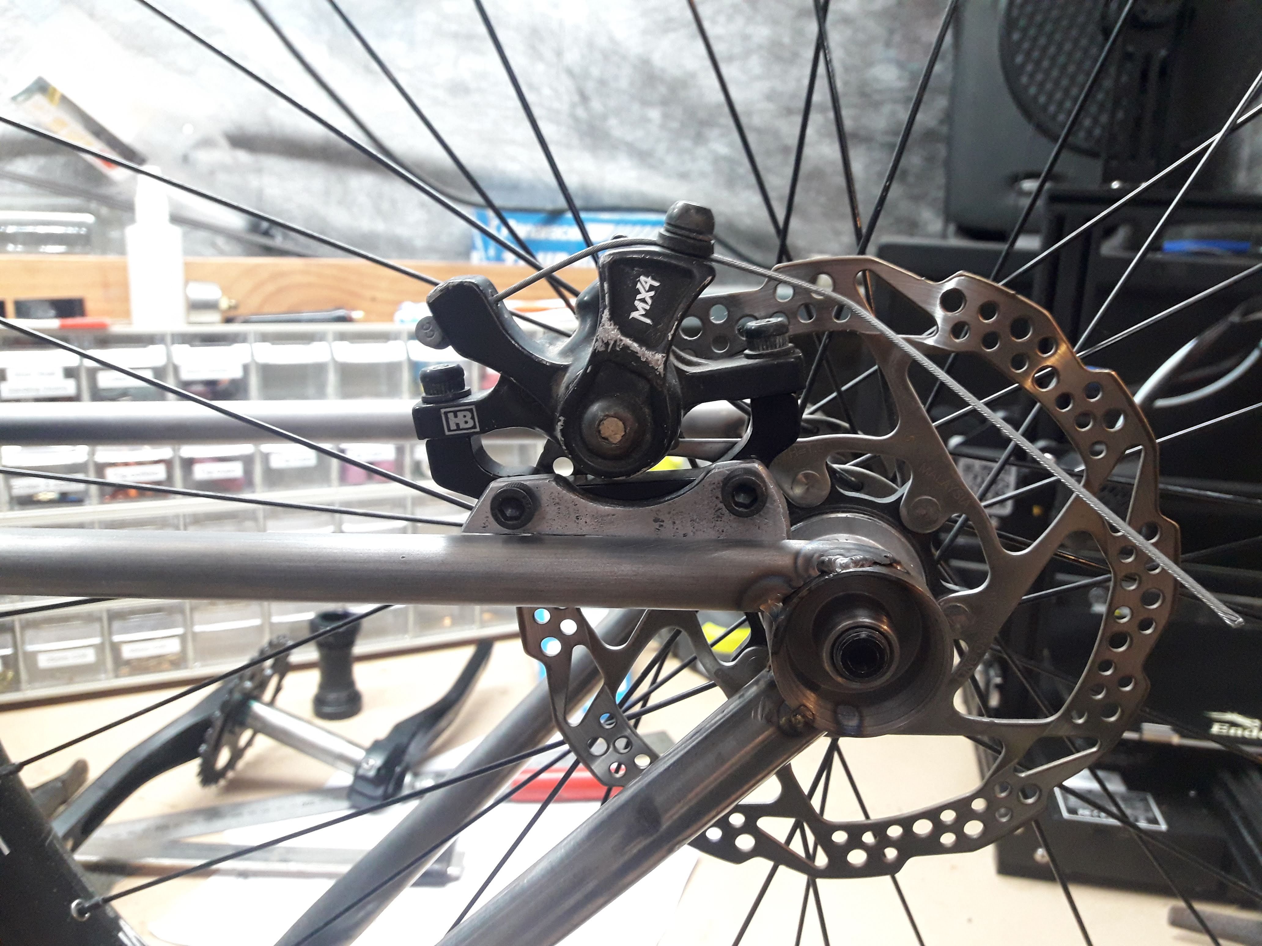
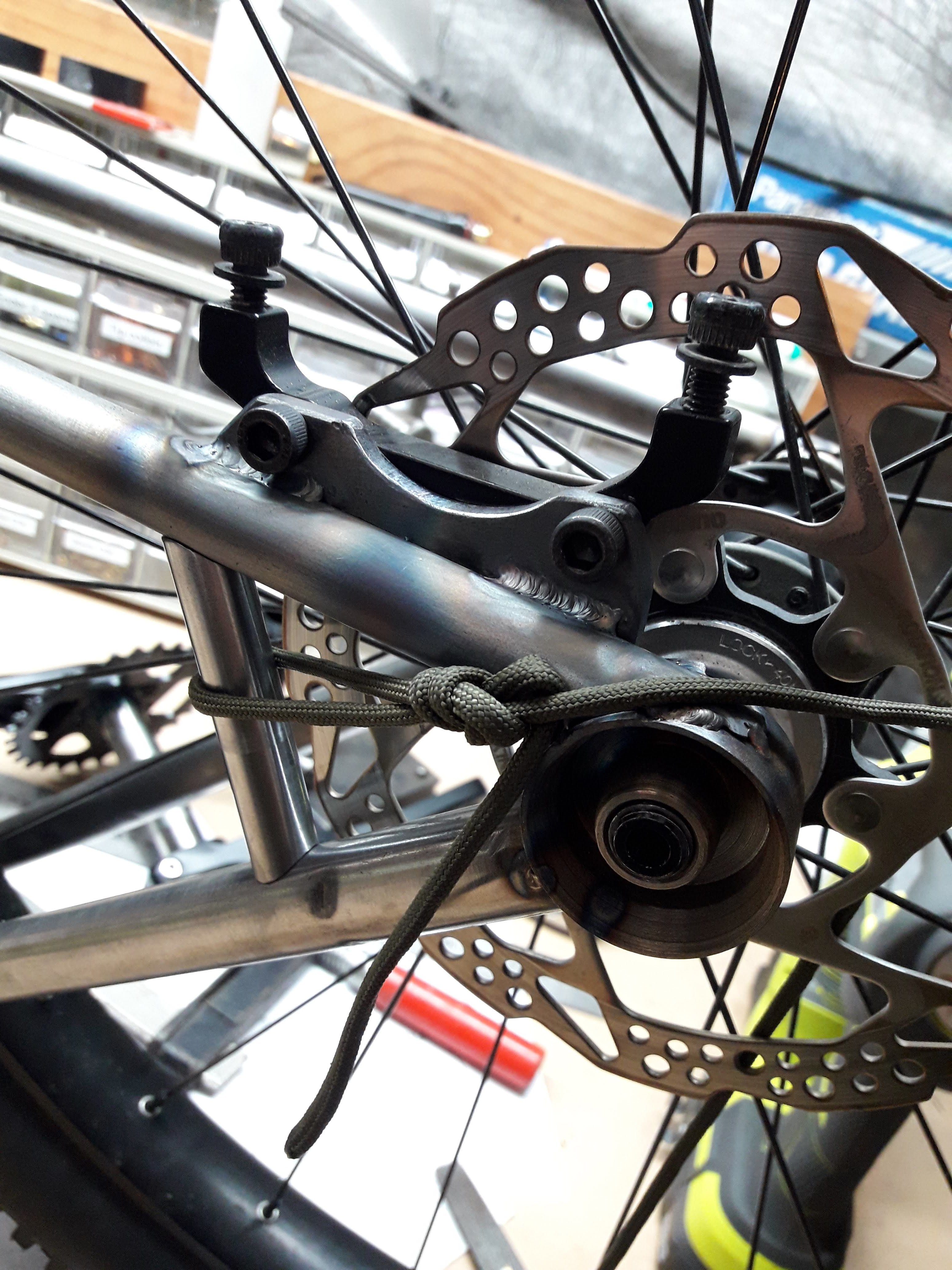
I put the wheel in with a rotor on and used a cable disc setup to clamp the caliper on to the rotor with the mounting plate bolted to it. Then tacked it to the frame as much as I could with that setup in place and then welded on alternating sides. The rear one is aligned mint, front I think has a tiny bit of an alignment issue but I will try tune that out later with a bit of bending/whacking/filing etc.
Are you planing on putting discs on your old timey mountain bike?
-
1
-
-
2 minutes ago, tortron said:
could have used a rivnut
")
i ebay'd some vintage braze ons a while ago, probably got a pack floating about still
What kind of braze ons? I have made what I need for this frame but could be keen on some for the next frame. It feels a little ridiculous spending an hour to make a $1 part but lockdown means there's time to kill so its not so bad.
-
Nobody likes to be dehydrated.
Therefore every bike needs a drink bottle holder! After having a rummage around I happened to have the right tap and drill in my stash of bits so I turned up some bottle bosses on the lathe and drilled the down tube for a bottle cage
A lot of the bits from here onwards I would really much rather have bought than made, but no where in NZ that I can find sells frame building supplies and I am too impatient to wait for 1-3 months for stuff to turn up from USA/UK.
I tig brazed these in, it is very difficult to get the silicon bronze to flow and I really didn't want to melt the base metal so amperage was pretty low.
Came out a bit lumpy, quite a lot of filing and sanding later it looks like this
Still kind of lumpy and weird, but good enough considering it will be hidden by a bottle cage once the bike is all together
-
3
-
-
- Popular Post
- Popular Post
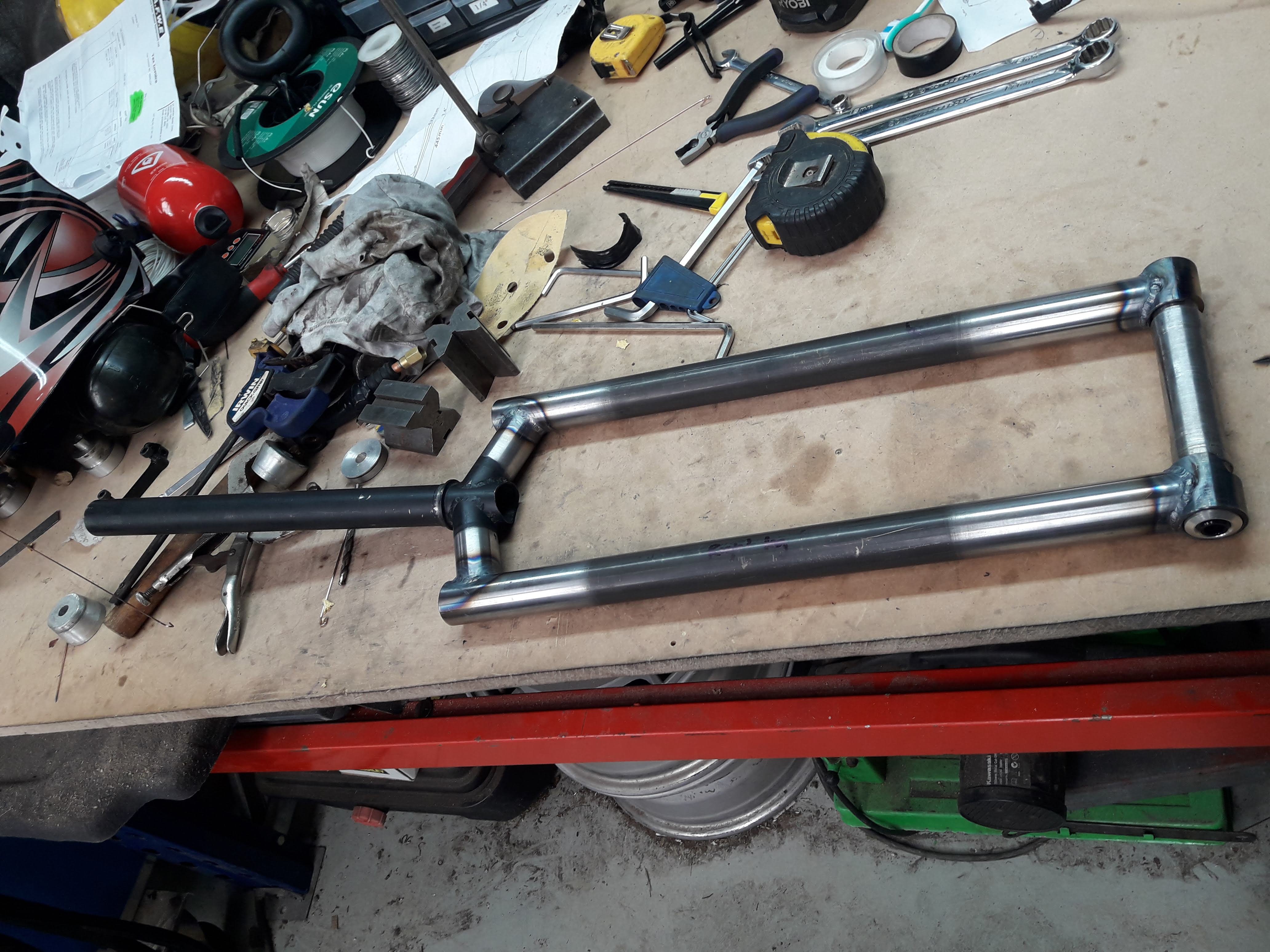
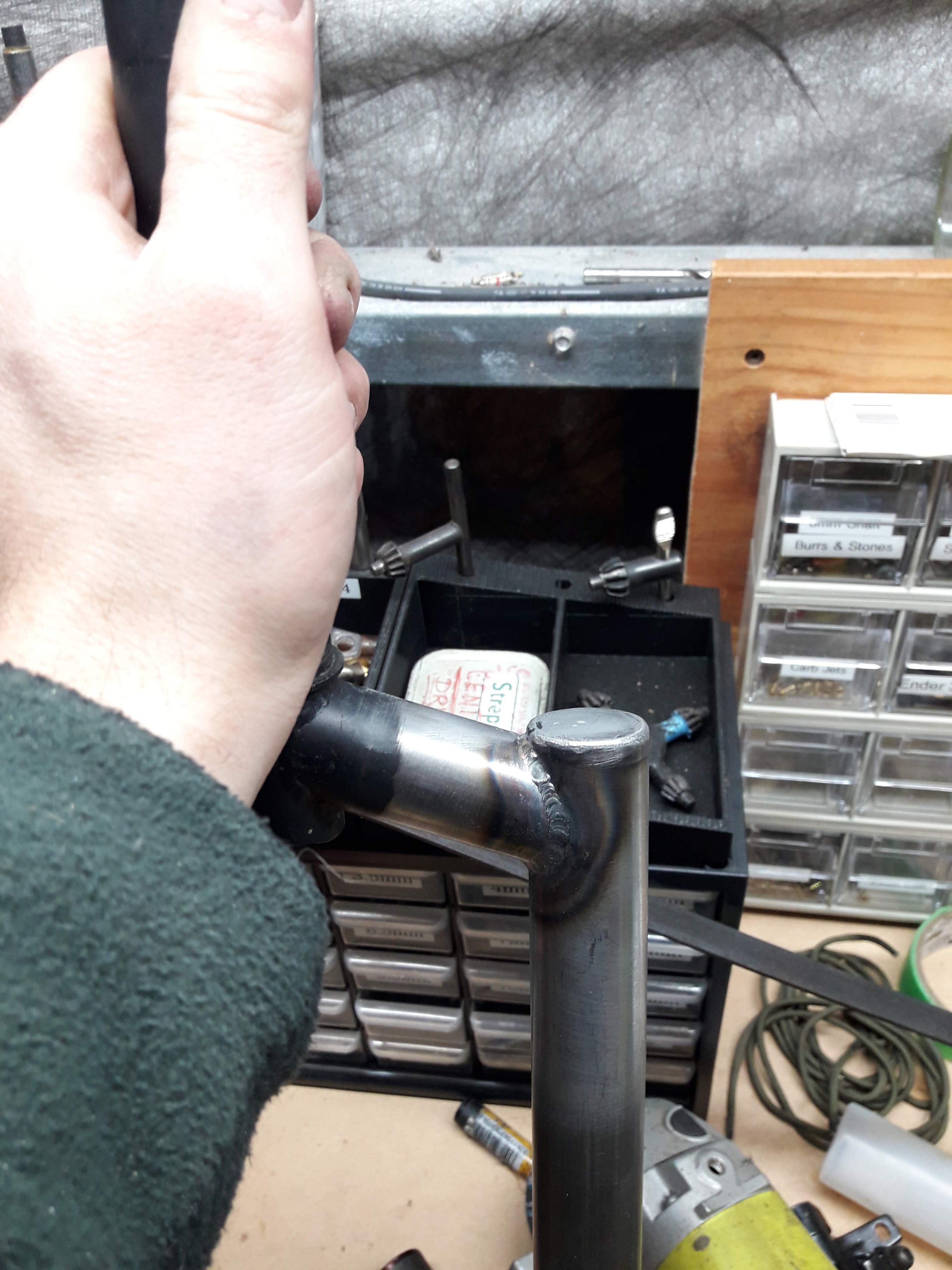
Fork welded together. Turns out my fork jig wasn't very good as the tyre centre was off by about 3mm. I saw this after tacking so I cut the tacks and re tacked not once,
not twice...
...4 times before managing to get it right. Sigh. Ah well its pretty straight now. technically it means the faces of the dropouts are probably not perfectly aligned but never mind, it looks good.
I made a IS brake mount and popped that on too
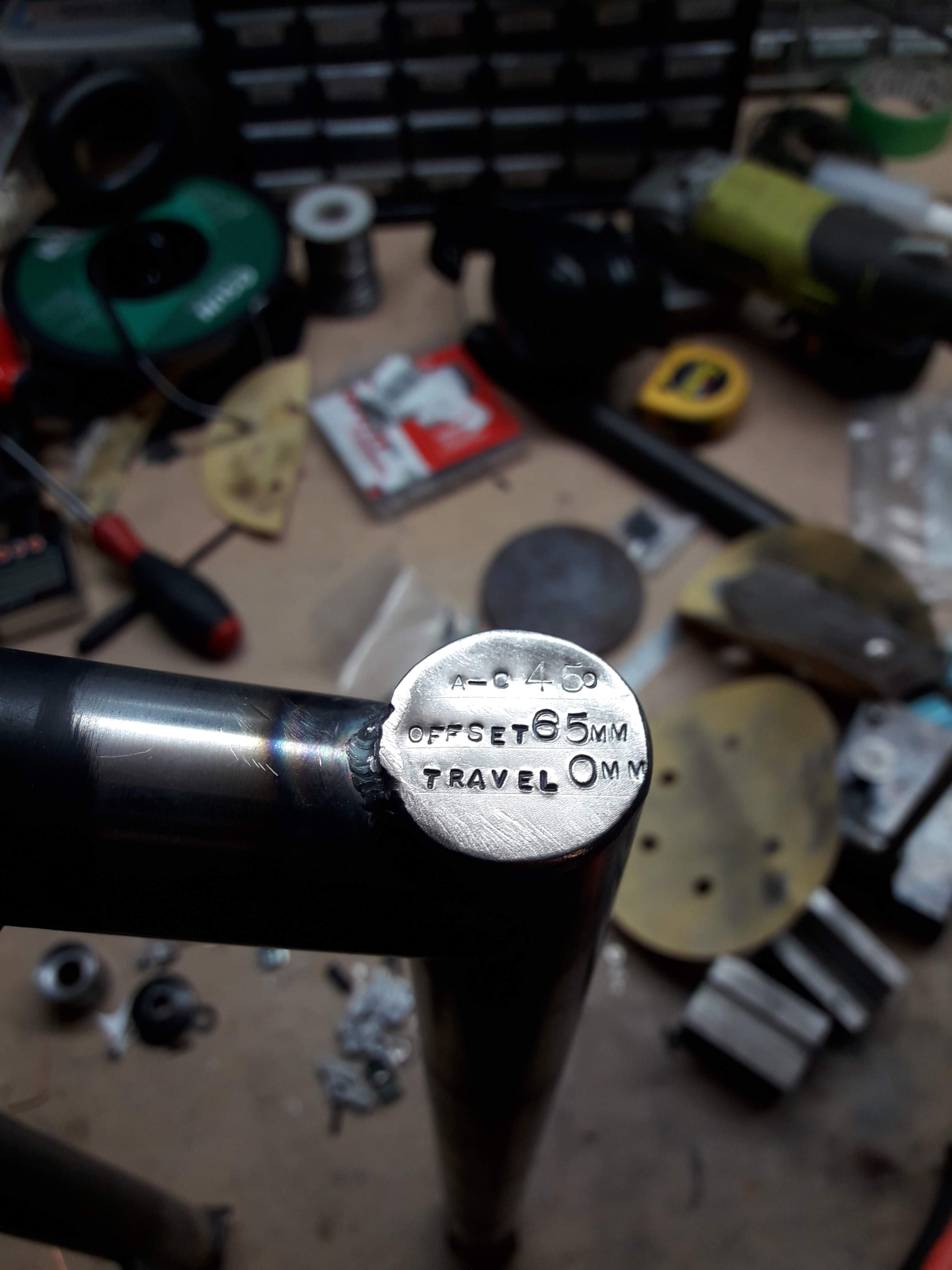
And top cap no. 1
And on top cap no. 2 I stamped the fork specs
-
17
-
 2
2
-
It's been a little while since I updated this. Things are moving along nicely, though waiting for stuff to arrive off aliexpress is currently jamming up the works but there is plenty for me to post about for the time being.
The last piece of tube to go in the frame was cut and mitred by hand, it's a bridge for the seat stays. I decided against putting in a chain stay bridge in after lots of research, apparently they were originally added to bike frames as a attachment point for the mud guard and serve no purpose past that. I checked my Ragley hard tail and it doesn't have one and I give that bike a seriously hard time so I think it should be fine without it.
Next up was to get started on the fork. I mitered the crown section that @ThePog kindly donated to make it a bit narrower. To get the mitre on the right angle in relation to the steerer I needed to chock up the rear end of the fixture. It ended up being a bit of a compromise between getting the right angle for offset (I think it was about 6 degrees) and the centre height of the tube correct for boring. So it ened up being mitered on centre at 1 or 2 degrees less than ideal and I went in there with a file afterwards to tidy up the join . Probably could have gone a bit narrower as it still has clearance for a 4" tyre which it will never have, but the shape looks kind of cool and a bit different.
There's about a 2 degree taper in towards the dropout. I recon it looks kind of cool. Axle to crown is 450mm, Offset 65mm.
I decided on the offset after reading up about tyre flop and mechanical trail. I found a calculator on the video below (its in the description) and put in the specs for a bunch of different bikes and decided to go to the far end of high offset.
I figure this bike can be a bit of a test bed for steering geometry for me to figure out what to do for the next bike, as such it will probably end up getting 2 more forks made for it. Another 450mm a-c and 35mm offset which would be the extremely low end of offset for this bike, and another with offset determined by what I like from fork #1 and #2 and a-c height closer to 410mm. This would bring the BB height down by about 20mm, steepen the seat tube angle and headtube angle by about 2 degrees.
-
6
-
1
-
-
- Popular Post
- Popular Post
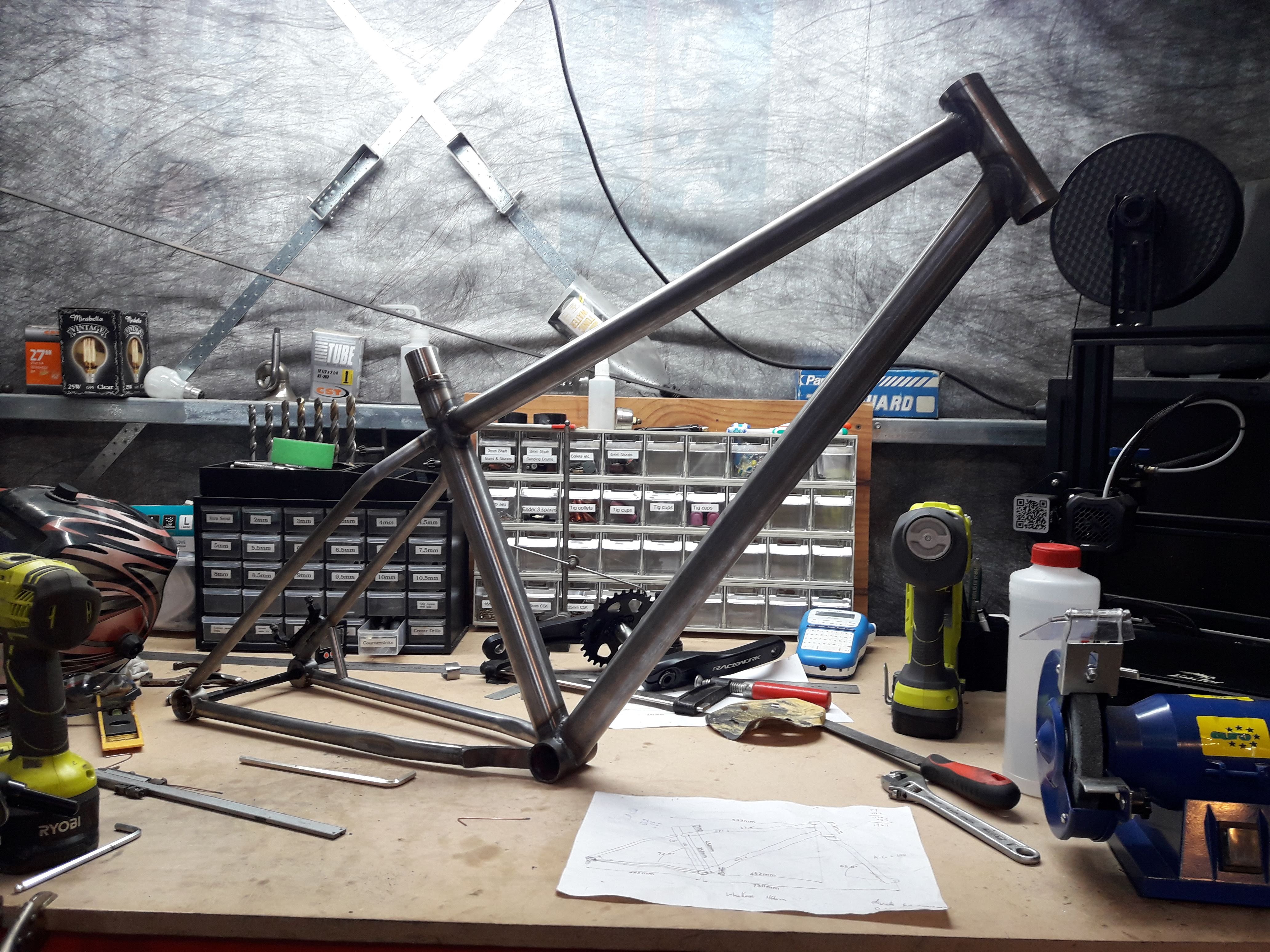
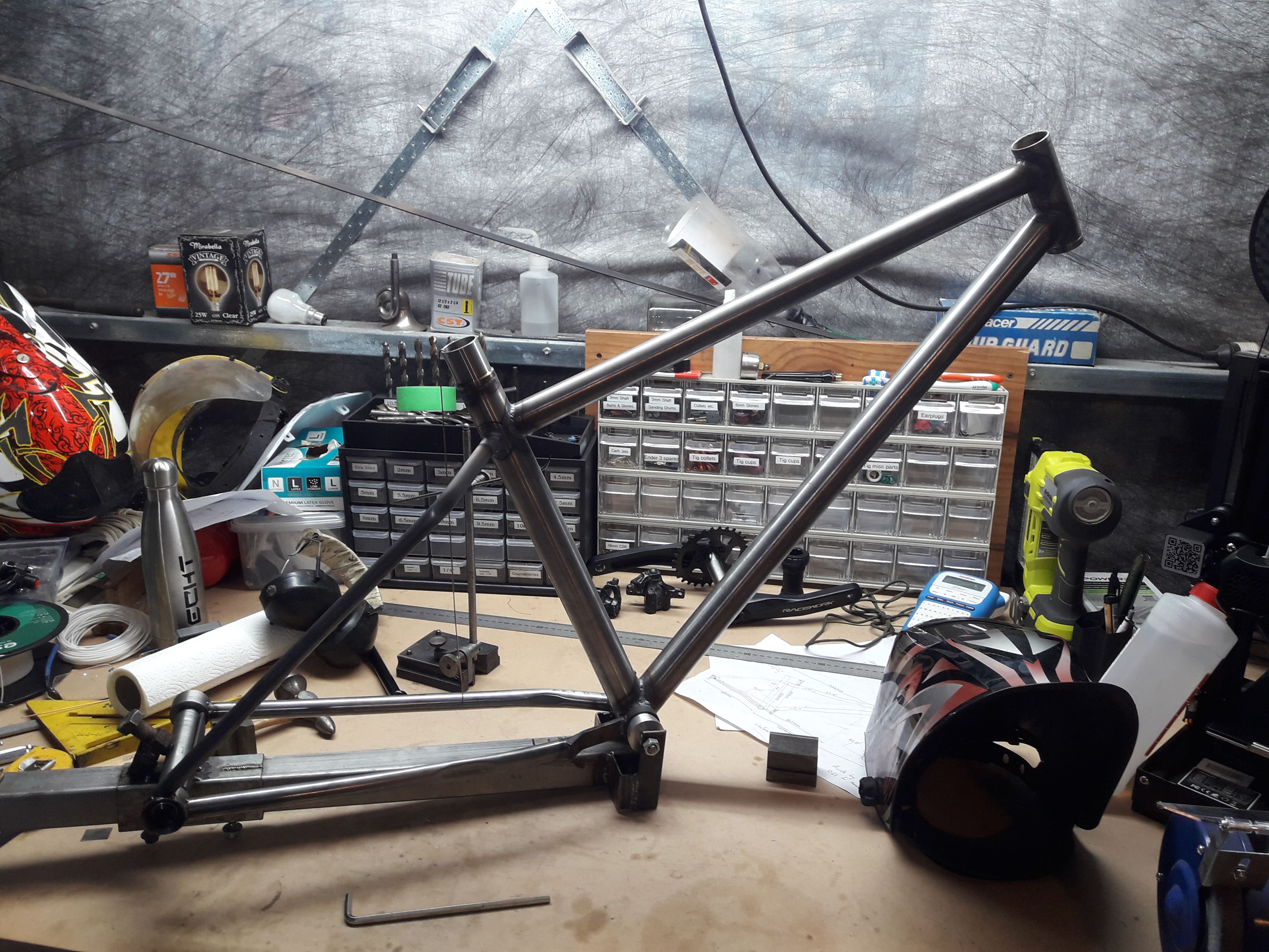
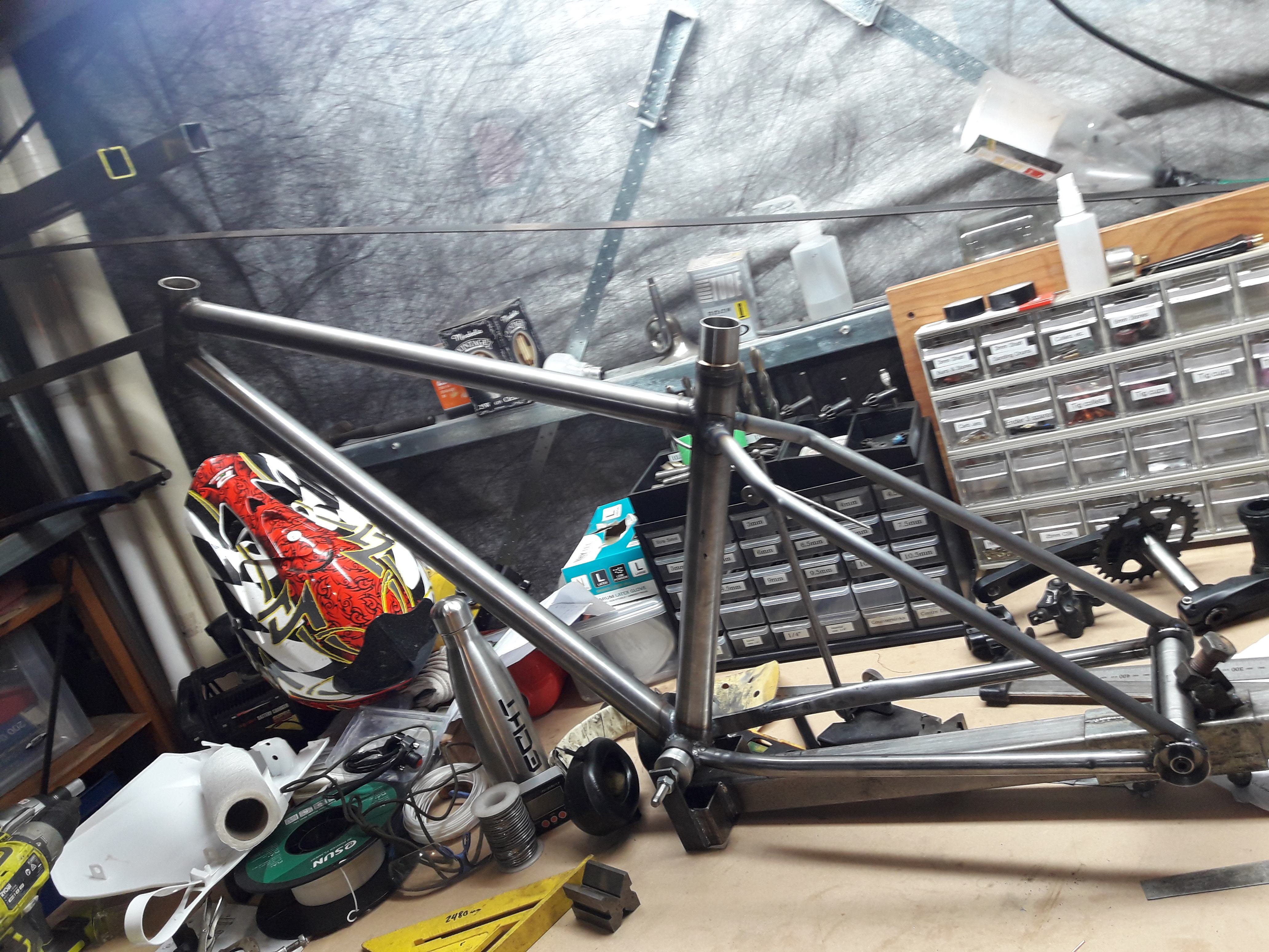
Pretty stoked with how it's looking. There's an annoyingly long list of things that need doing before its done though.
I decided to make a headtube badge since I cant do any welding for the time being. Went with a pi symbol (π) because Guypie. or Guypi. whatever, its a simple logo to make. Just printed out a page of various size Pi's and offered them up to the headtube and picked the one that looked about right. glued it to a piece of stainless and lots of drilling/cutting/grinding/filing later came out with this:
I think I am going to glue it to the head tube cause its too small to weld and being stainless. Maybe silver solder but I haven't done that before, I'm open to suggestions. Does a normal plumbers torch put out enough heat to get silver solder flowing? Alternatively recommendations on what kind of glue would be welcome.
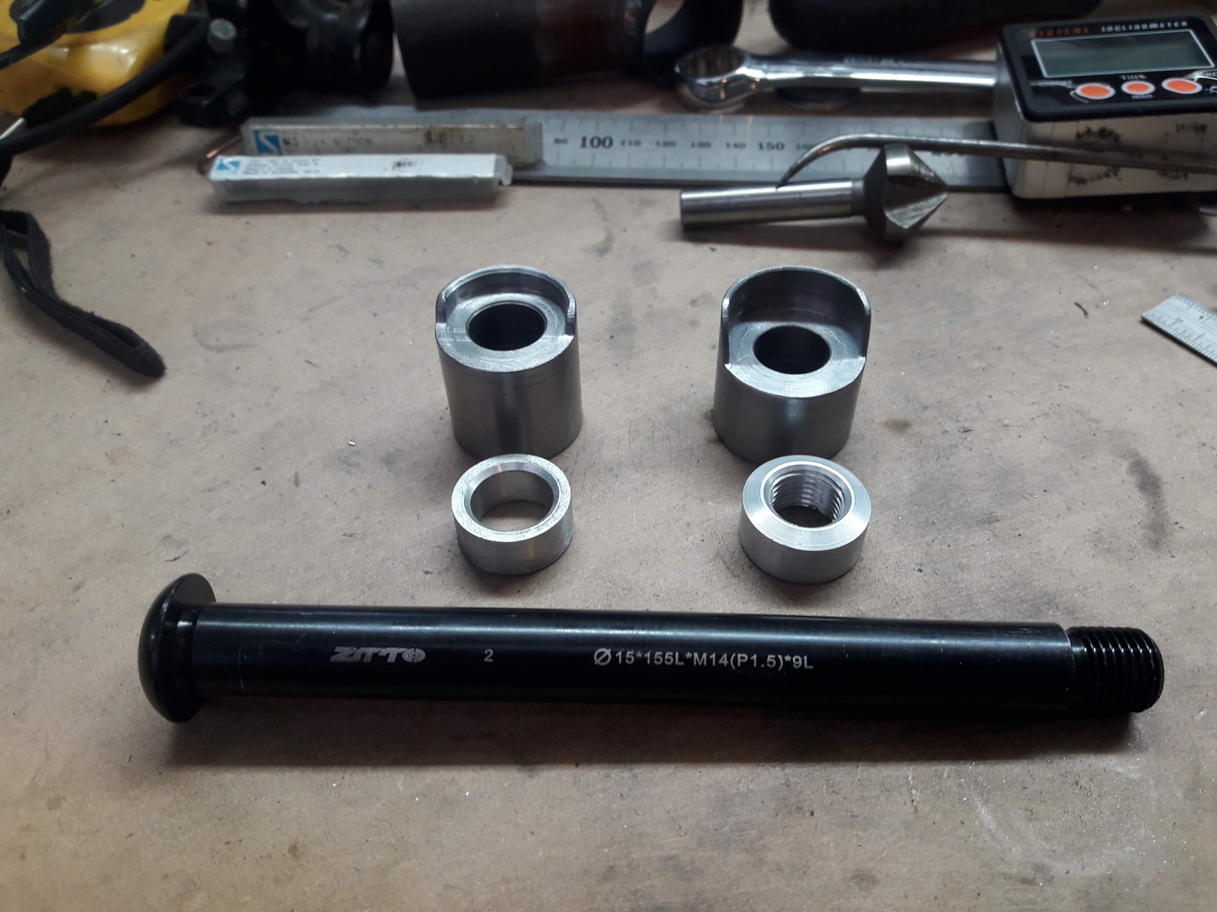
I also spent a long time turning up some fork ends to suit the axle and wheels I have, this is what I came up with:
The reason they are different sizes is because I initially made them both like the one on the right, but it interfered with the wheel. Really I should have remade both of them but I couldn't be bothered, it just means the fork legs will be slightly asymmetrical. Everyone knows that asymmetrical = high performance right. Best tyres? asymmetrical. Best mtb rim profile? asymmetrical. Best ROI? asymmetric return.
Clearly it's going to be a winner.
-
10
-
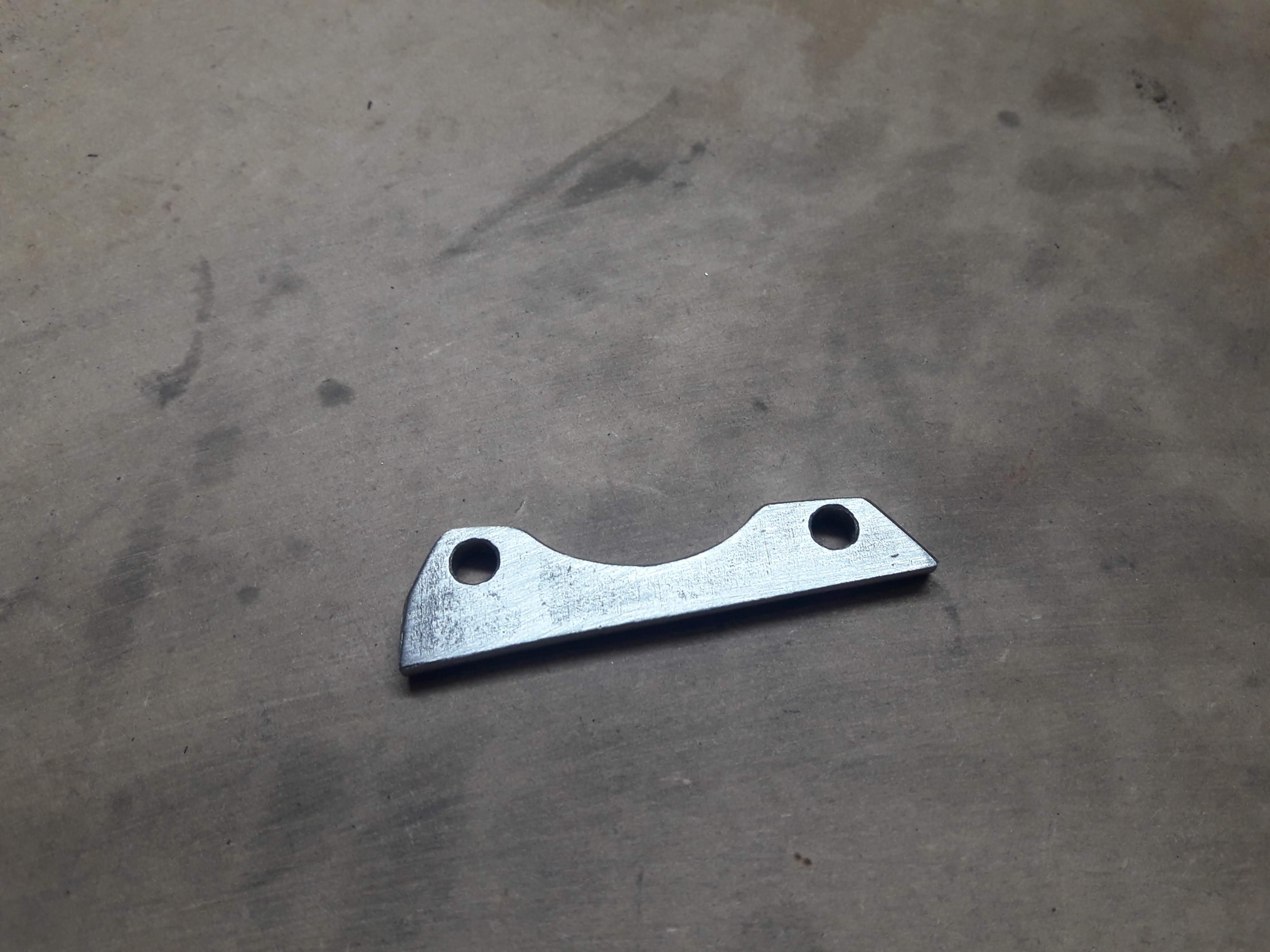
Added a brake tab to this last weekend
And thats all of my argon until payday comes around. I have be puttering along doing all the non weldy things for the last week. I put a little bridge between the chainstay and seatstay as apparently disc brakes are too much for skinny little tubes to handle long term.
-
6
-
-
- Popular Post
- Popular Post
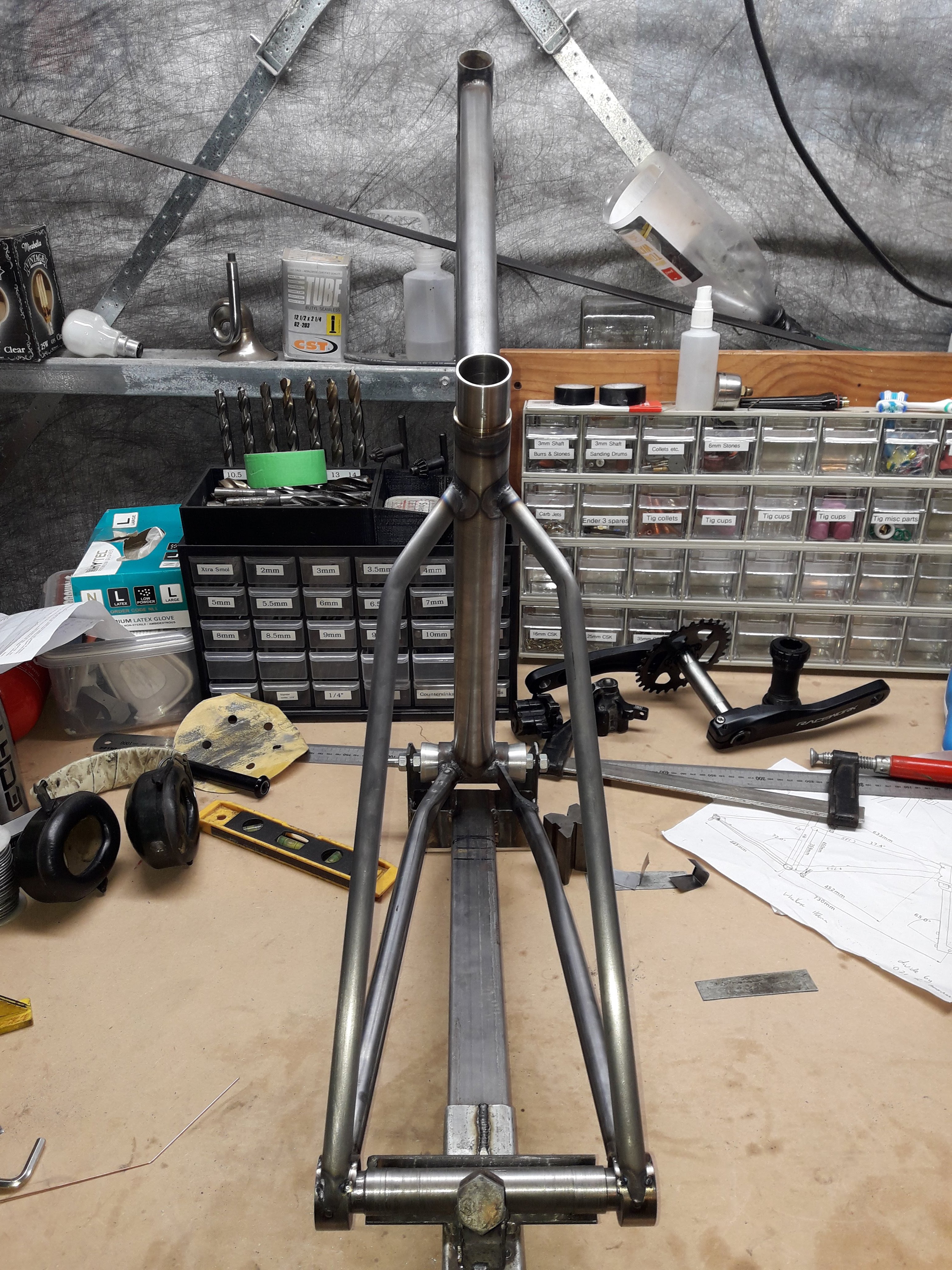
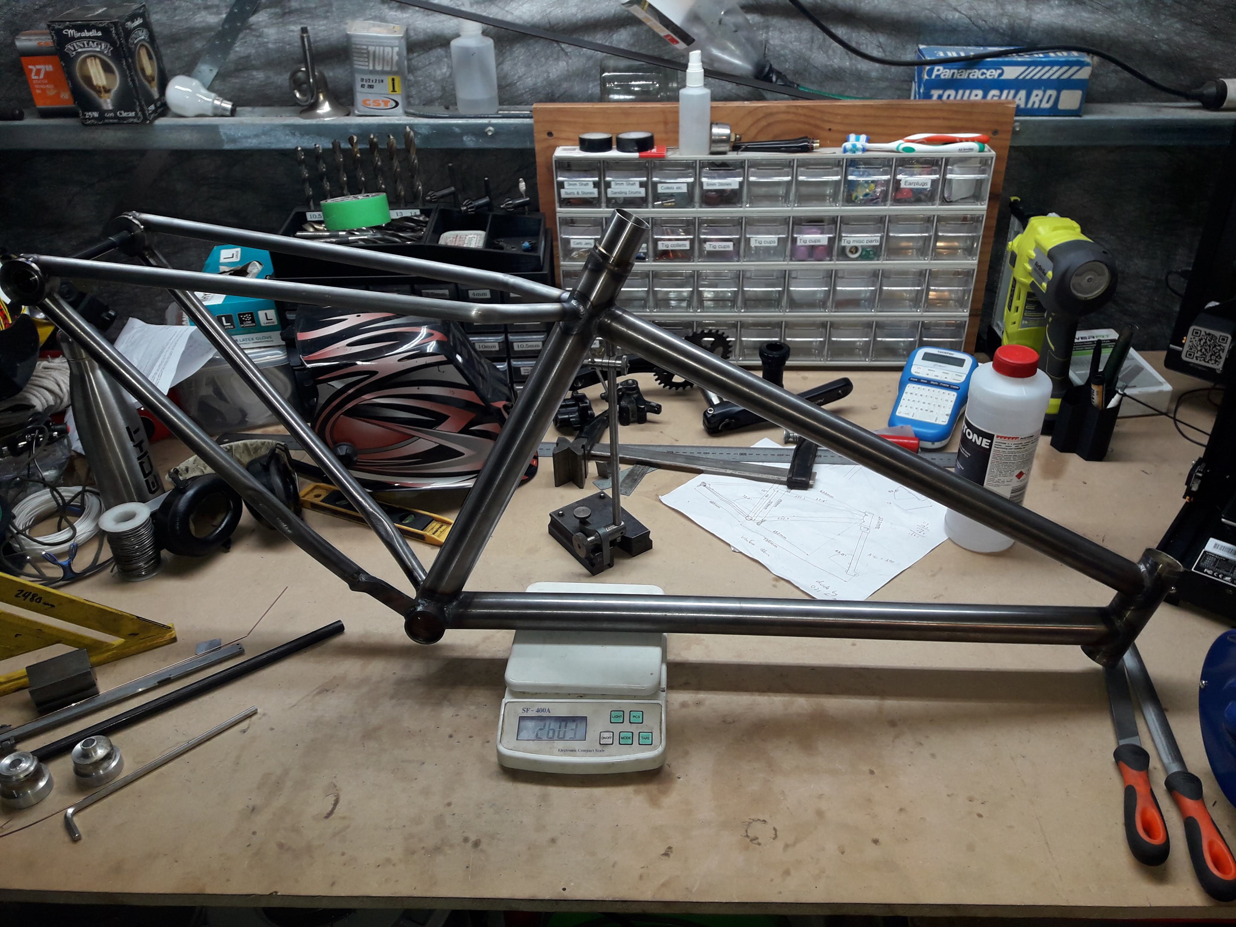
View from behind. Not much in it really.
Chucked it on the scales. Its on track for 2.7kg ish final weight which was about what I was expecting
-
10
-
1
-
Thanks for the suggestions, will have to give springs and/or sand a jam for the next lot of bending I do.
Seat stay 1 in place:
Then seat stay 2:
These were all hand files because I was too lazy to make a seat stay mitering jig. I think I will for the next one cause one is a little bit higher than the other due to it needing more filing before ending up with a nice tight joint which bothers me slightly. Though you cant see it unless you are looking for it so its really not too bad.
-
7
-
-
Next up is getting set up for bending seat stays. I bought a 3 ton arbor press cause I figured it would be nice piece of kit to have for fabricating things. The seat stays are 5/8" tube .049 thick (about 1.2mm, most of the other tubes are .035"/0.9mm for reference) so I needed to make some tooling for the press to bend these, hopefully without kinking. I turned some form tools out of 51mm ali I had lying around and then turned off the bottom of one piece for the press tool.
The piece to the left I needed to cut in half for supporting either side so I resorted to the scary tablesaw of death. I screwed it down to a sled with a piece of angle iron and hid behind the sled while feeding it through.
My gamble with tablesaw russian roulette paid off and the part was cut fairly cleanly, though not quite as even as I had hoped. Still, didn't really matter for what I had in mind
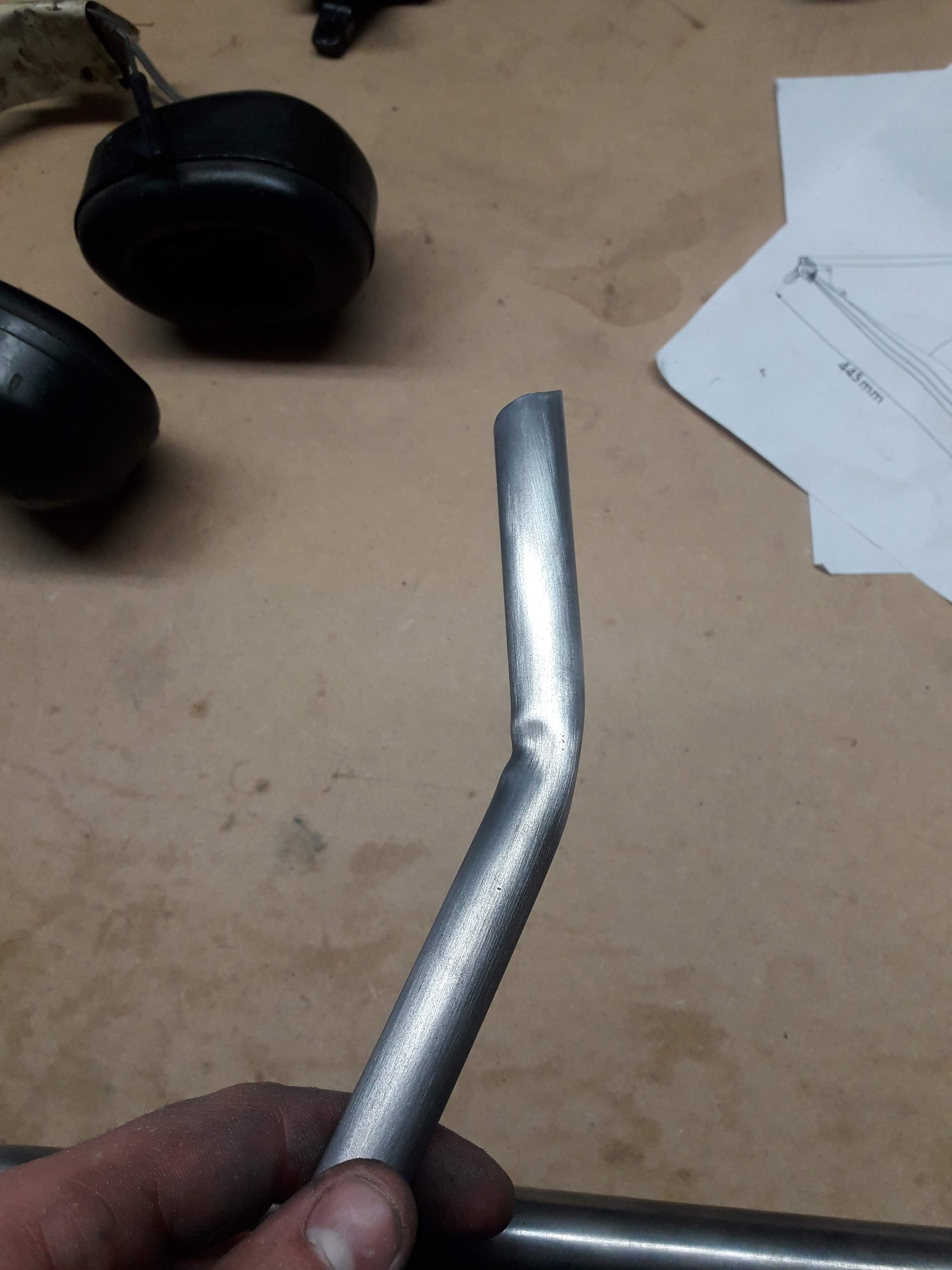
Gave it a press and the bend came out...
... with a horrible wrinkle on the inside. Sigh. This photo actually makes it look far worse than it is, so I just went ahead and used it anyway considering this piece of material is about $30 worth @ 460mm long. For the second stay I did some file work on the upper tool to increase the radius of the bending form and it was much better.
-
5
-
-
3 hours ago, SOHC said:
Came with 3 chucks, a faceplate, and some tool holders but I need a live centre and drill chuck for the tail stock
I saw that on Facebook, was a bargain.
-
1
-
-
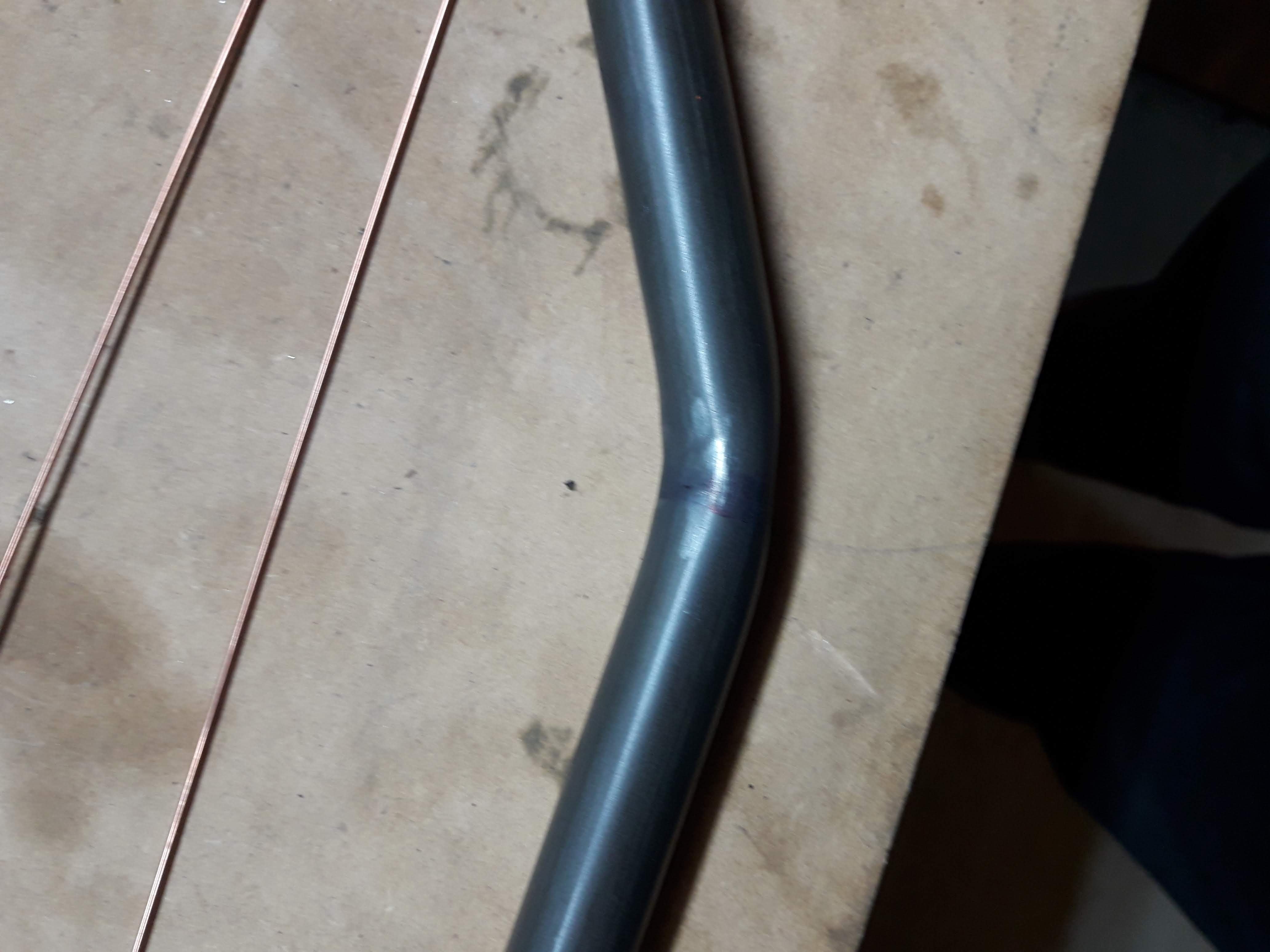
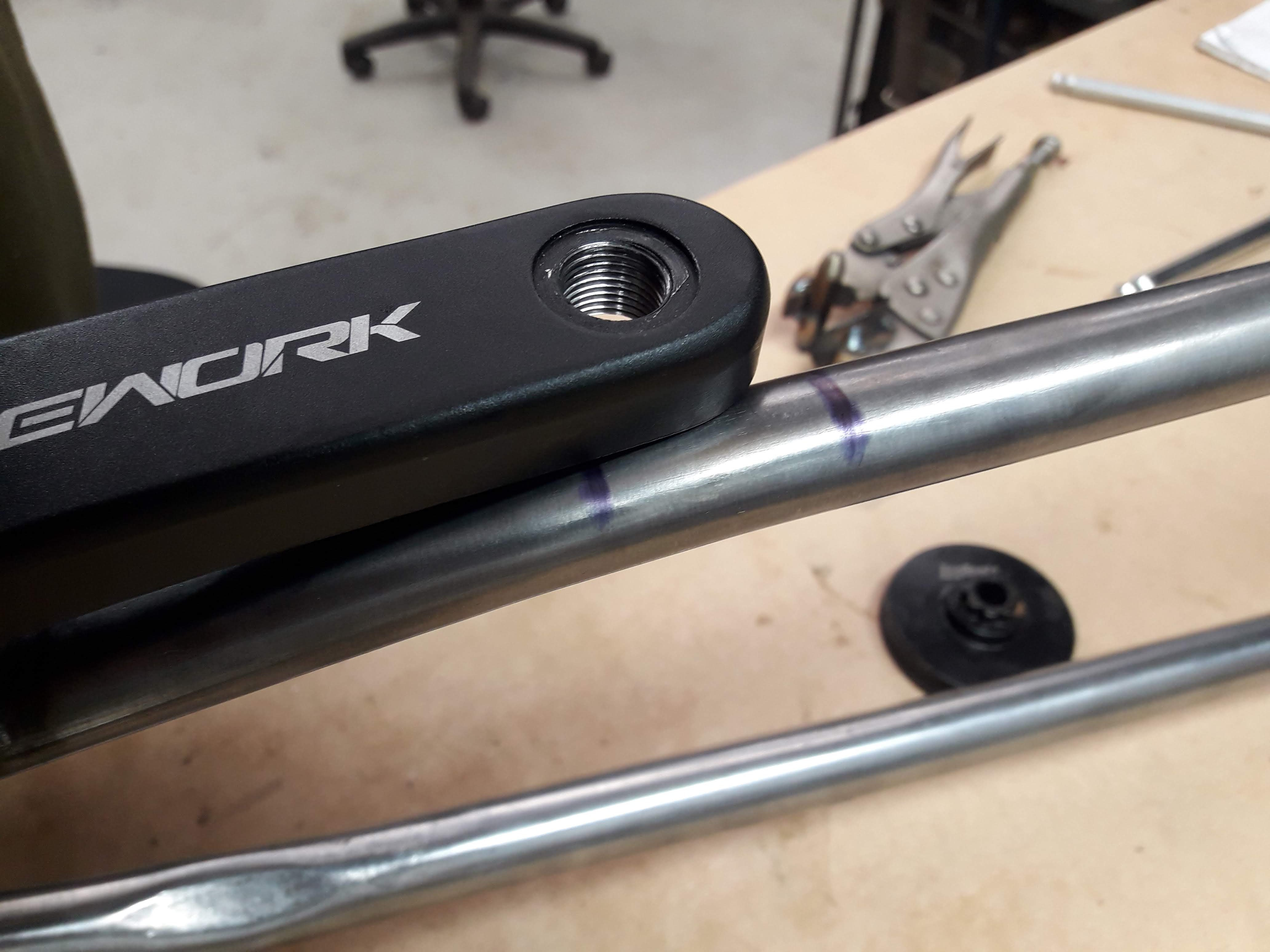
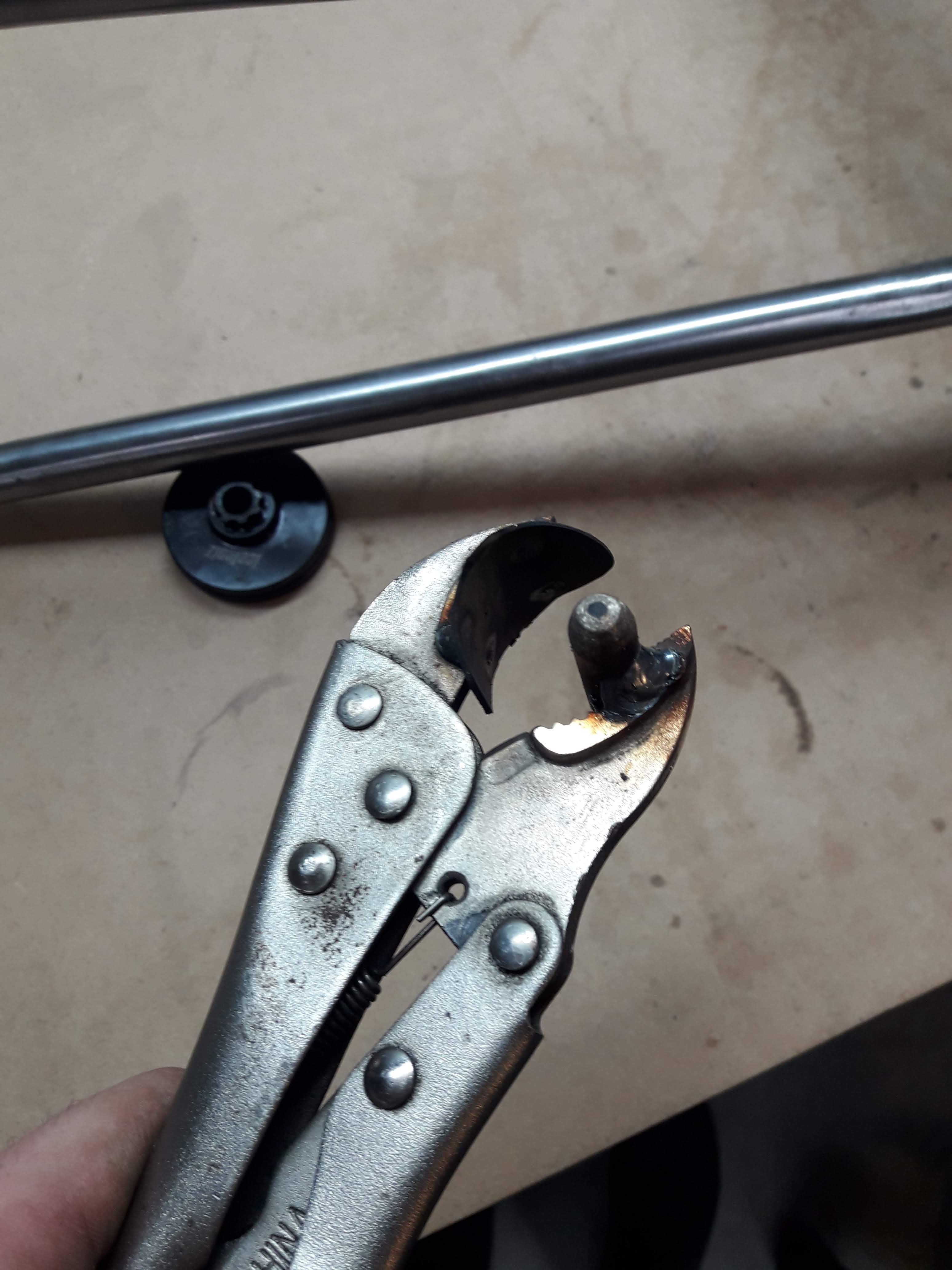
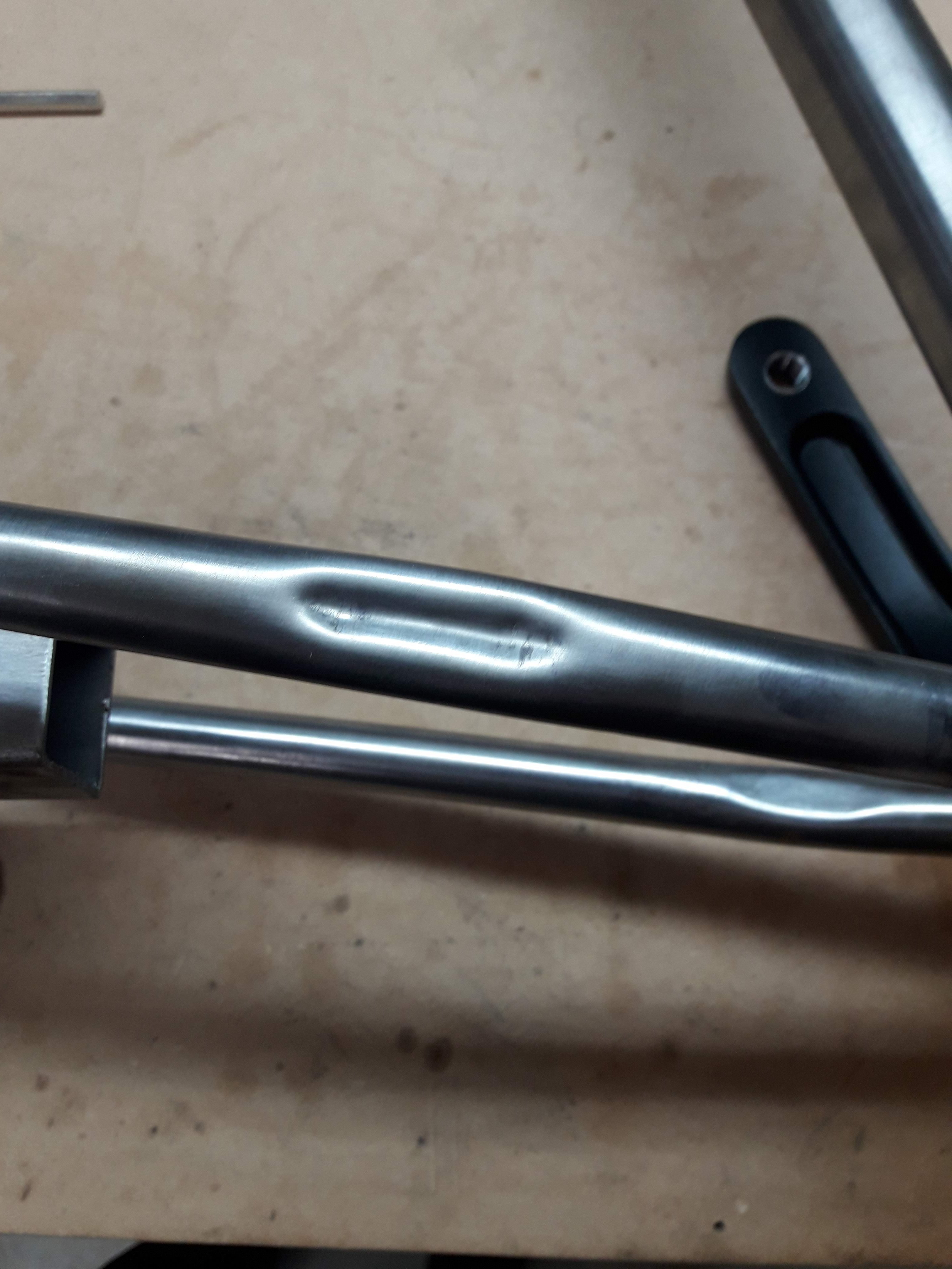
I welded on the chain stays next, then decided to pop a crankset on to see if I managed to stuff up the chainring clearance. Turns out the chainring clearance was fine but the crank arm on the drive side had a slight issue:
Oh dear. So I put together a dimpling too to make a bit of clearance like so:
A bit of a squeeze and things were good to go!
I might need to revisit this later as under load it might flex into the crank arm but thats a problem for future Guypie.
-
9
-
-
I started on the non drive side chain stay. It was a seat stay donated by the vintage marin (RIP) I gave it a little bit of a tappy tap with the hammer on the inside of the curve to tighten up the radius and tacked it in place
I figured I should check for any clearance issues before going any further so I unbolted the rear axle and rotated it in the jig then threw the wheel in and gave it a spin:
I forgot to take any pictures of the drive side stay before I tacked it in place. It is a chain stay from the marin which interestingly had 3/4" chain stays and seat stays, and I made a bridge to clear the chainring out of a piece of hardox 450 4mm plate. Hopefully the hardox works out well, 4130 plate is ludicrously expensive.
the piece of wood in the middle is a very rough and ready tyre clearance gauge to make sure I don't make any silly mistakes while tacking it together
-
5
-
-
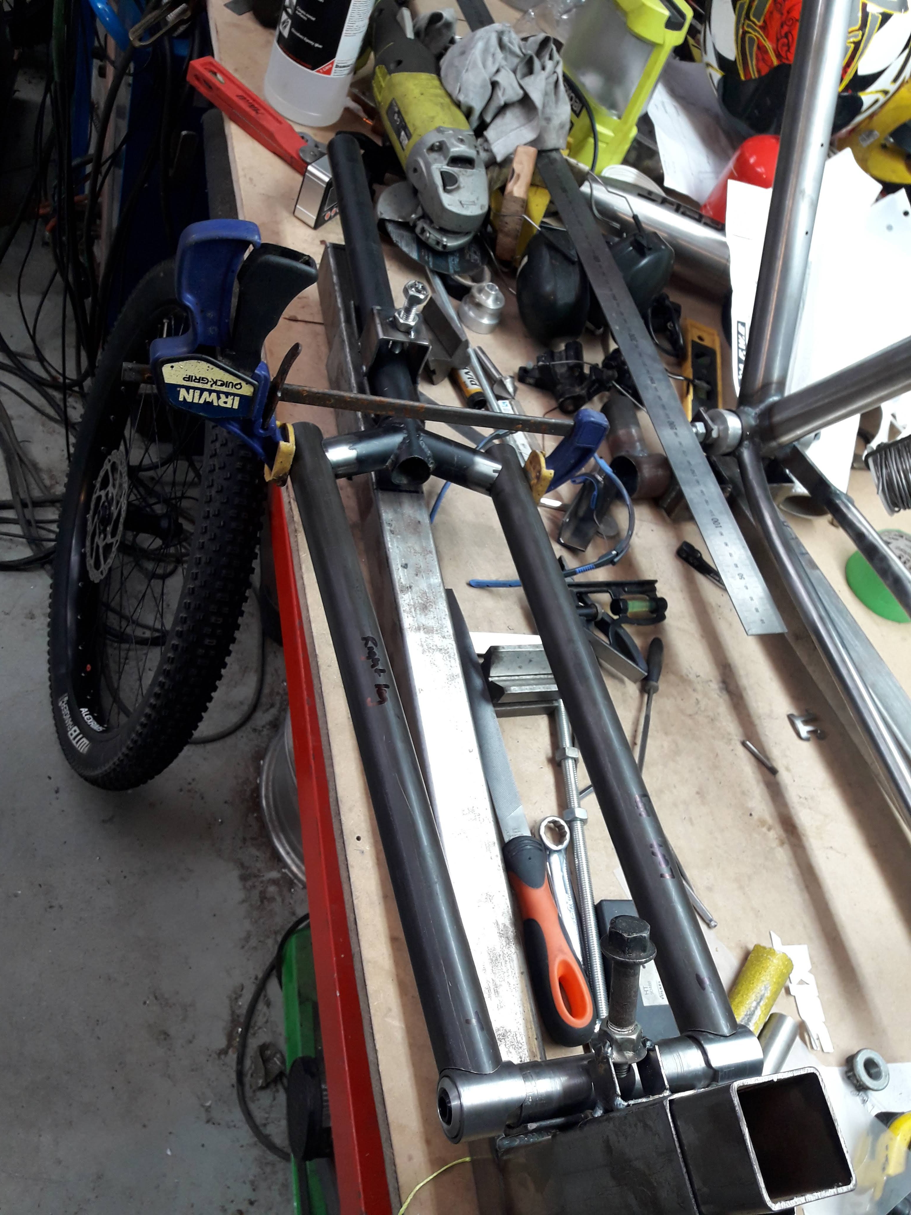
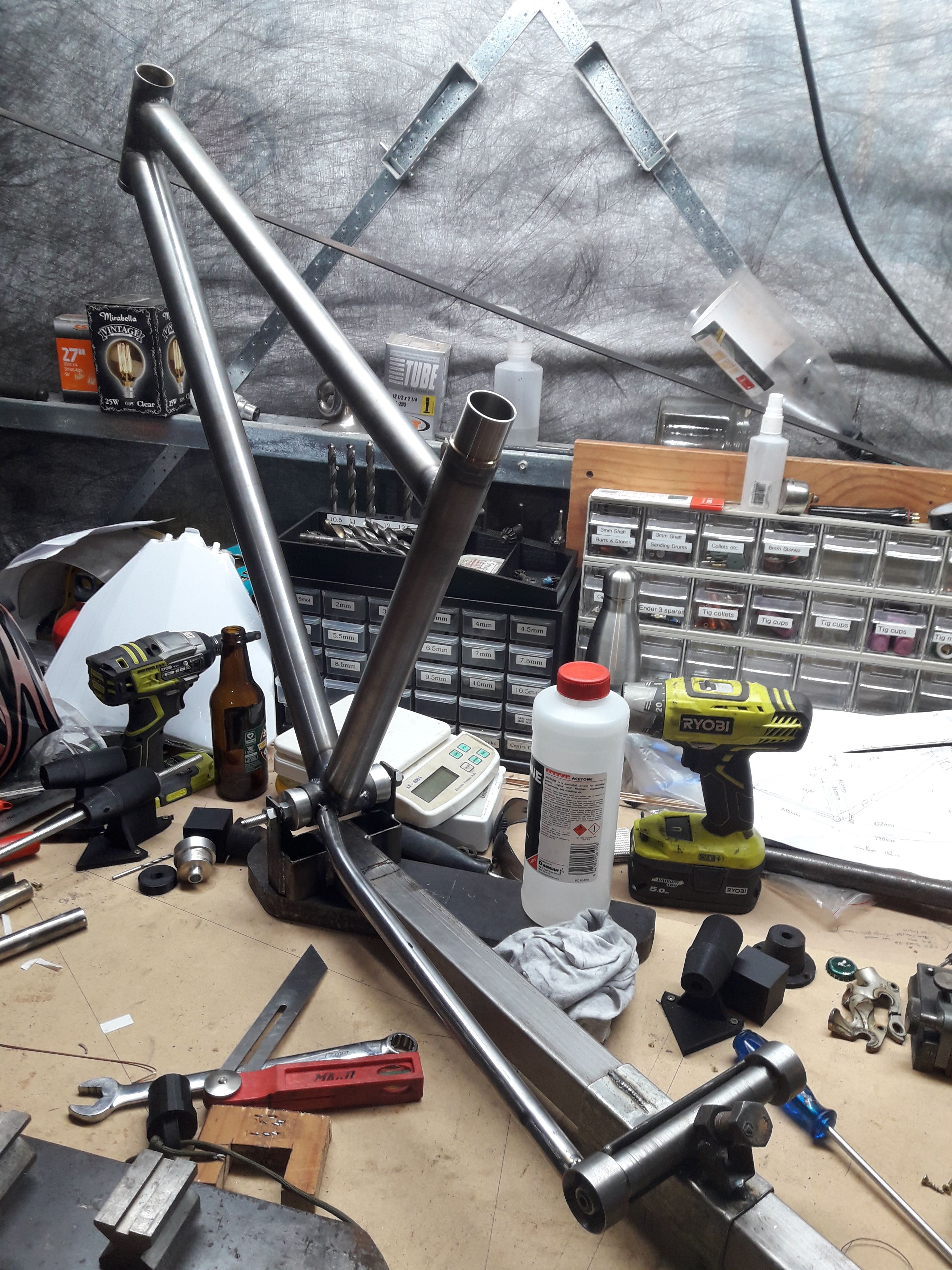
I have managed to get a bit more done on this in the last couple of weeks. Here is a terrible picture of my BB to rear axle jig.
I won't be using this again, for the next build I will make a proper jig. But it got the job done.
I filed the bottom of the lip of the frame ends flush so that when you have the bike tipped upside down to pop the wheel in there's a ledge for them to rest on. The horrendous surface finish on the dummy hub in the jig is a bit weird. I have a bunch of lengths about 300mm long of some sort of medium tensile steel that was the offcuts of a CNC job from a friends workshop. I cannot figure out how to get a decent finish on it, it just always comes out with a very torn up looking surface. I have tried a few different tool geometries, different feeds and speeds, always comes out looking like balls.
BB is centred on cones. The other reason I will be going with a new jig next time around is that there's barely any space in here for the 68mm BB shell. I only used that size because that's what the old marin had. Next time I think I will buy a new shell in 73mm.
(or maybe 83mm...)
Also those 2 holes from the old chainstays were a pain, I had to patch them as the new stays didn't line up with the holes. not sure if I took a photo but it looks a bit of a mess in there. fortunately that little nook is always just jammed full of mud anyways so as long as I don't clean the bike it should be well concealed.
-
3
-
-
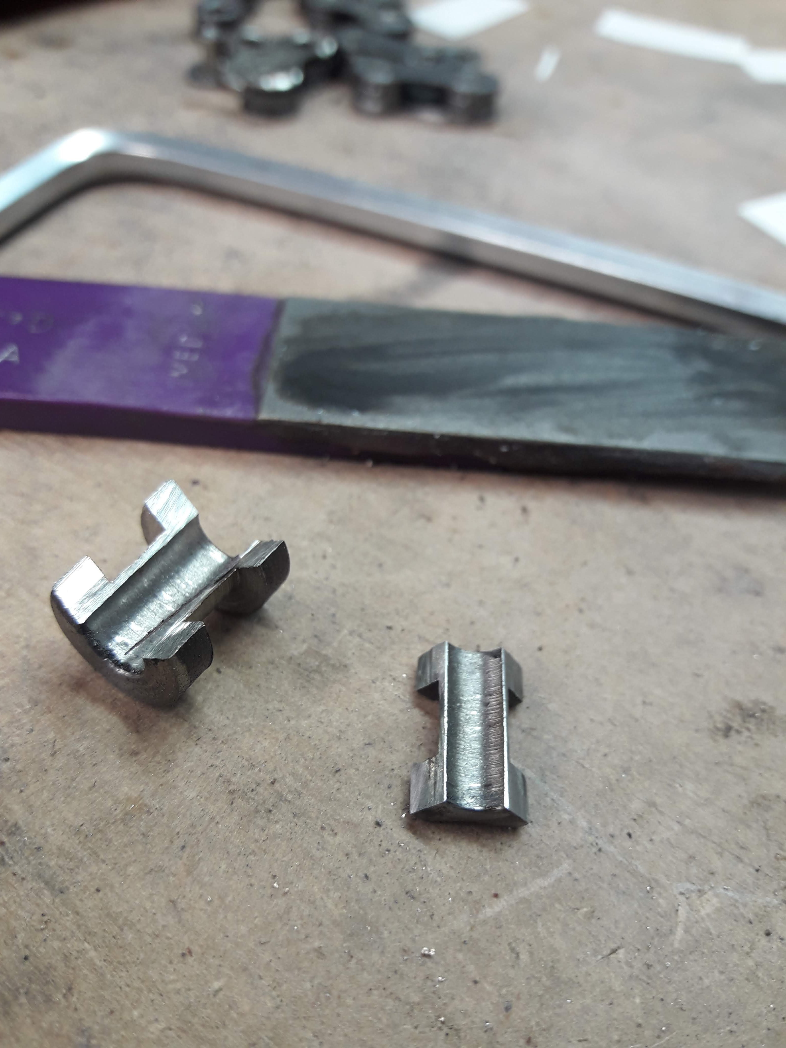
And it came out like this. fairly yuck
after heaps of fileing/sanding/scotch bright it looked a bit like this:
Its kind of ok, but I'm not really happy with it. So with about a days worth of work in it I decided to scrap it and start again.
Today I spent most of the day turning these out of some mystery steel from my box of offcuts:
They look a bit like oldschool skateboard wheels. Much more happy with the outcome, I need to cut the shroud parts down to the correct size so I will probably go get a nice new file tomorrow and just do it by hand. I had a little test run on the lathe putting it off centre with the 4 jaw chuck. It would work but it was mildly terrifying, not to mention if the jaws slipped on the workpiece it could turn it to scrap metal real quick
-
4
-


.jpg.9b091efc13947ee87d3595144e90376c.jpg)


Guypie's Bike Builds - A paint job and more!
in Two Wheels
Posted
Theres too many mistakes on this when you look at it in person. I will probably do that on the next frame since the welding has improved somewhat over the build.