

kws
-
Posts
4,175 -
Joined
-
Last visited
-
Days Won
5
Posts posted by kws
-
-
I was going to try that but found one random silver drill bit in my cabinet, which managed to cut 3/4 of the way through before snapping. Off to bunnings to buy some more
Guess the repco ones arent worth the rubbish bin.
-
i have good access to it under the car, so i guess i could. What benefit is annealing it to removal?
-
I need to drill out a stud in my exhaust so I can fix a leaky flange (big fuck you mazda for using a pressed in stud instead of a nut and bolt). My cheap drill bits don’t even scratch it.
Where can I get good drill bits (without paying a fortune) and what should I look for? Mine were just a cheap set of HSS (allegedly) ones from repco.
Needs to be done on car with a cordless drill so no fancy drill press.
-
SDwon

-
 3
3
-
-
They look so awkward at 4x4 spec. Needs lowering
-
3
-
-
Its taken a while but im finally repping.
-
6
-
-
Spotted some old stuff at Pick A Part in the Hutt today.
Not sure if Left to rot or spotted.
-
3
-
 1
1
-
-
Thats Project Rusty. Not sure on the wheels personally, but what a mint car.
https://www.drivelife.co.nz/2017/10/project-rusty-robs-audi-ur-quattro-part-30-wof-time/
-
I have sikaflex 227, is that a seam sealer? Sort of looks like it is but I’m guessing there are a lot of different types.
im not certain if I’ll use the original wing or make a replica to use on the car. Guess it depends on how good I am at fibreglassing.
-
A sticking trip counter that won't reset is a common "feature" of the SD1, and one that I'm keen to fix on my car.
Handily a spare speedo cluster was one of the parts I picked up on the weekend. This also had the sticky trip counter, so I decided to practice on this and if it works well then when I remove my cluster to swap the better lens over, I'll fix my cluster too.
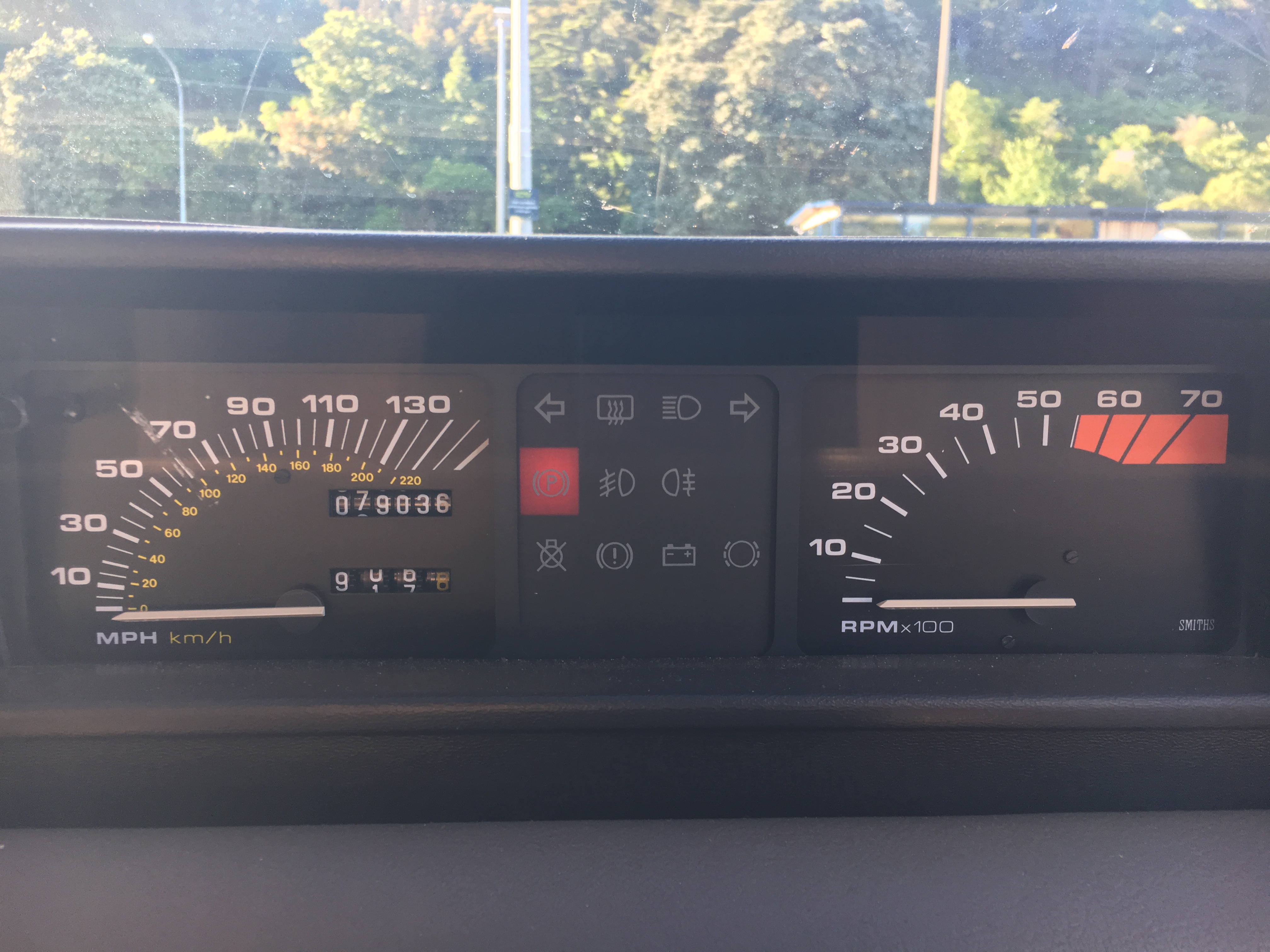
Heres the willing victim, legit Smiths gauges
You can see the lens although dirty is generally in good shape with only small marks on it. My current one was "marked" at the 60MPH/100KPH mark; obviously the previous owner had issues seeing the open road speed
Removing the lens is easy enough once the gauge is out, so working on the spare cluster, I removed the four screws and off came the lens
Another four screws and off comes the front surround
These four little nuts are the only things holding the speedo into the housing. Remove these (and take care of the little washers behind them) and the dial will pop out the front
This is the reset mech. The white lever gets pushed down by the button when you press it, which moves the little gears away from the numbers
I pulled the needle and dial face off so I could investigate the internals more and understand why it isn't resetting
Button not pressed
Button pressed
At this point all the numbers should spring to zero. Clearly it isn't working. On a whim I tried spraying some silicone spray onto the mechanism, and bam, everything freed up and suddenly it all worked like it should. The numbers all popped to zero
Now, obviously it's a lack of lubrication in the mechanism that is binding it all together and making it stop working. I suspect that if you're careful and drop a couple of drops of oil into the mech you may not even need to remove the needle and face. This is promising, next I'll try on my real cluster and see if I can fix it.
Moving along, whilst here I removed the tacho to see why my one seems to show signs of dry solder joints. It worked occasionally, and when it didn't a swift whack on the top of the dash would bring it back to life. It'd be nice to reconnect, fix it and have it working again. Three screws on the rear and out the dial comes.
Woo, 8 cylinder
I suspect this little board, being the only place with solder on it, is the source of my issues
Its stuck down with some double-sided tape, which I cut through with a razor. The solder is only on the top of the board, not through hole. There isn't much room to work, but I suspect if im careful I should be able to clean up and resolder the joints on the board.
That's where I'm at for now. I'll need to remove my cluster and do some work to it, now that I have an idea of what im doing. Good start.
-
1
-
-
1 hour ago, Threeonthetree said:
Triples as the boat too.
Puhuhuhuhu
Quadruples as a sieve too
-
21 hours ago, KKtrips said:
CEA negotiations stuff - all the normal to-ing and fro-ing. But the union have walked away from the table and rejected every single claim the company has made while the company has accepted every claim (except one) that the union has made.
Although the only one that I care about is changing the wording from "you may be requested to work on public holidays" to "you may be required to work on public holidays"Thats not what they are making it sound like, theyre trying to make it all personal like the big bad companies are trying to screw the employees.
-
I couldn't help myself, I HAD to work on the wing and see what condition it was in.
So the other day one of the amazing parts I scored from Whanganui was this original Vitesse rear wing.
These are crazy hard to get hold of these days in NZ, unless you buy a fibreglass replica from Rimmer Bros in the UK, for around $270 + shipping.
The Vitesse was the only model to get these spoilers. Rumour has it they increase stability at speed, and may even reduce fuel consumption by altering the coefficient of drag. According to Karen Pender's book the standard 1982 3500SE (no spoiler) had a coefficient of 0.405 whilst the early Vitesse was 0.360. The only body changes between the two cars was the spoiler.
Plus, they look awesome; they just finish off the back end so well.
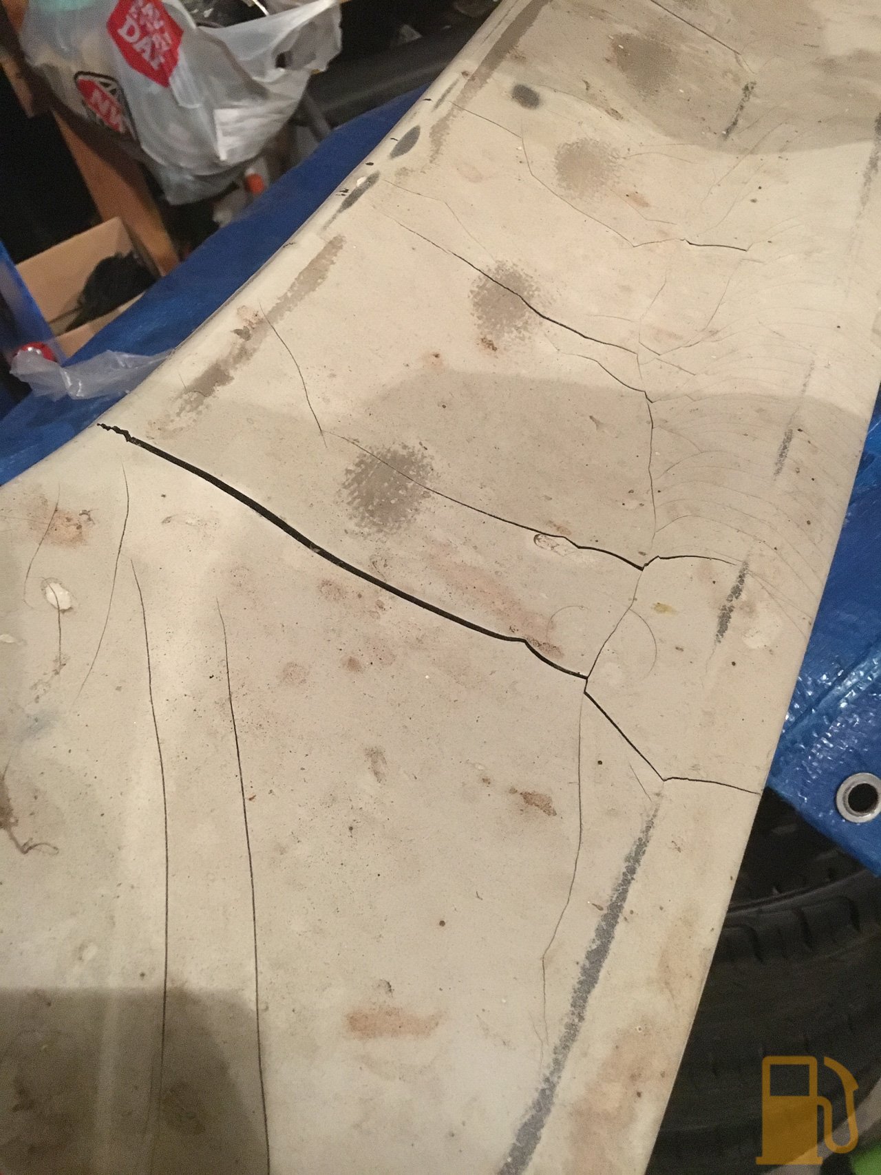
So yes, I now have one in my possession. Unfortunately the previous owner had painted it white, and it was in bad condition. The paint was cracking badly, and the rubber wing itself was cracked in a couple of places.
I started with stripping the paint off to see what state the rubber was in. Initially I tried 80 grit sandpaper by hand but wasn't getting anywhere as the paint was so hard and thick, so I moved to an 80 grit flap wheel on my grinder. I very carefully used this to strip off as much paint as possible, without cutting into the rubber.
I decided to grab a DA orbital sander today and have another go. This was far more effective, and I managed to remove most of the paint
This shows clearer how badly cracked the rubber is
You can also see there that I still have some paint stuck in the rough texture where the wing has weathered. I'll leave this as is, as I don't want to dig into the rubber to remove it.
The standard Vitesse wing attaches by about 6 studs to the boot lid. Obviously my car doesn't have the holes for the spoiler, and I'm not keen to drill into it, so will be looking to attach it with Sikaflex or the likes. This meant removing the studs from the spoiler, which isn't a hard job, when only two remain.
Using my Dremel and some sweet aliexpress cutting disks I cut them off as flush as possible. I also used my flap wheel to grind them down some more (after the photos were taken).
Once it had dried off a bit I decided to have a quick test fit.
Does it belong here?
Mmm, probably not. What about here?
A bit better, but still not quite right. What about here then?
Yeah, that's the stuff! It wouldn't hold itself on the boot lid, so no full photos as it's not mounted.
I did some thinking regarding the condition of the wing. Obviously I cant just stick it on as it is as it looks pretty rough, so I need a plan. I think what I'm going to do is take a fibreglass mould of the wing, and make a fibreglass replica and then mount that on the car. I'll store the original wing away safely.
This is a good thing for a couple of reasons. Firstly I won't need to uprate my tailgate gas struts as fibreglass is a lot lighter than the original wing; It'll also give me the ability to remake the wing if I need to, IE: if I get another SD1 that doesn't have one.
Now to add another skill to my set, how to fibreglass. Eek.
The MX5 is about to fall off its WOF, and its a couple of weeks until I can get it in for a WOF check, so until then I guess I'll just have to use and work on the Rover more. What a shame.
-
Legend, ill be taking thursday off then. Thanks!
-
Fine. Ill continue. Edit. Woo new page!
Started stripping the horrible white paint off the spoiler today. Its very thick, very hard and very brittle paint. I used a 40 grit flap wheel on my grinder and 80 grit by hand to cut through the paint. There are a couple of large cracks in the top of the wing, hopefully i can fill them with something, maybe sikaflex? and then ill be painting the wing in either bumper paint, or plasti-dip. Its a flexible rubber, so normal paint is a no go.
-
2
-
-
-
-
-
-
This is a rather long page.
-
I want all the Rover parts.
-
It's good knowing others with the same sort of automotive suffering as myself, sometimes they surprise you with opportunities like this one.
A friend and fellow SD1 owner (and also the Chairman of the local Rover club), Nick, had been following a lead on a couple of SD1s that were sitting in a backyard up in Whanganui. These cars were sadly left behind when the owner passed away, and his widow was looking at options to move them on. She was having trouble accepting that due to the condition of the cars they were going to be hard to sell for much, as none of them were complete, none of them had engines or trans and all of them were de-registered.
A few months pass and I get a call from Nick asking if I was interested in coming with him to check the Rovers out, and see what parts could be saved from them. It turns out the widow had given up and was going to scrap all of the cars. Understandably as soon as Nick heard this he jumped on the chance to save the hard to find parts that we all need to save.
Of course I'm never going to turn down a chance to have a look at some SD1s, let alone the chance to hopefully score some good parts for little money (and save the parts from scrap).
Yesterday we made the 4+ hour round trip to visit the cars. There were three cars left, out of what sounds like a possible four or five originally, so she had managed to find a home for at least one.
This is what greeted us
The red car was completely stripped, and had a whole range of various random bits dumped inside. Unfortunately these had been left out in the elements, so some of the good stuff was ruined. The red cars shell actually looked like a good rust free shell (other than the rusty tailgate) but it would be a lot of work to do anything with other than cut off repair panels.
The red car also had a strange looking coilover strut setup in the rear. The axle looked standard, and no signs of a rear swaybar or anything. Normally SD1s have separate spring and strut, not coilovers. One issue that has been found with some other cars changing to a coilover like this is that the metal where the top of the strut mounts was never designed to have that much force put on it, and can be damaged.
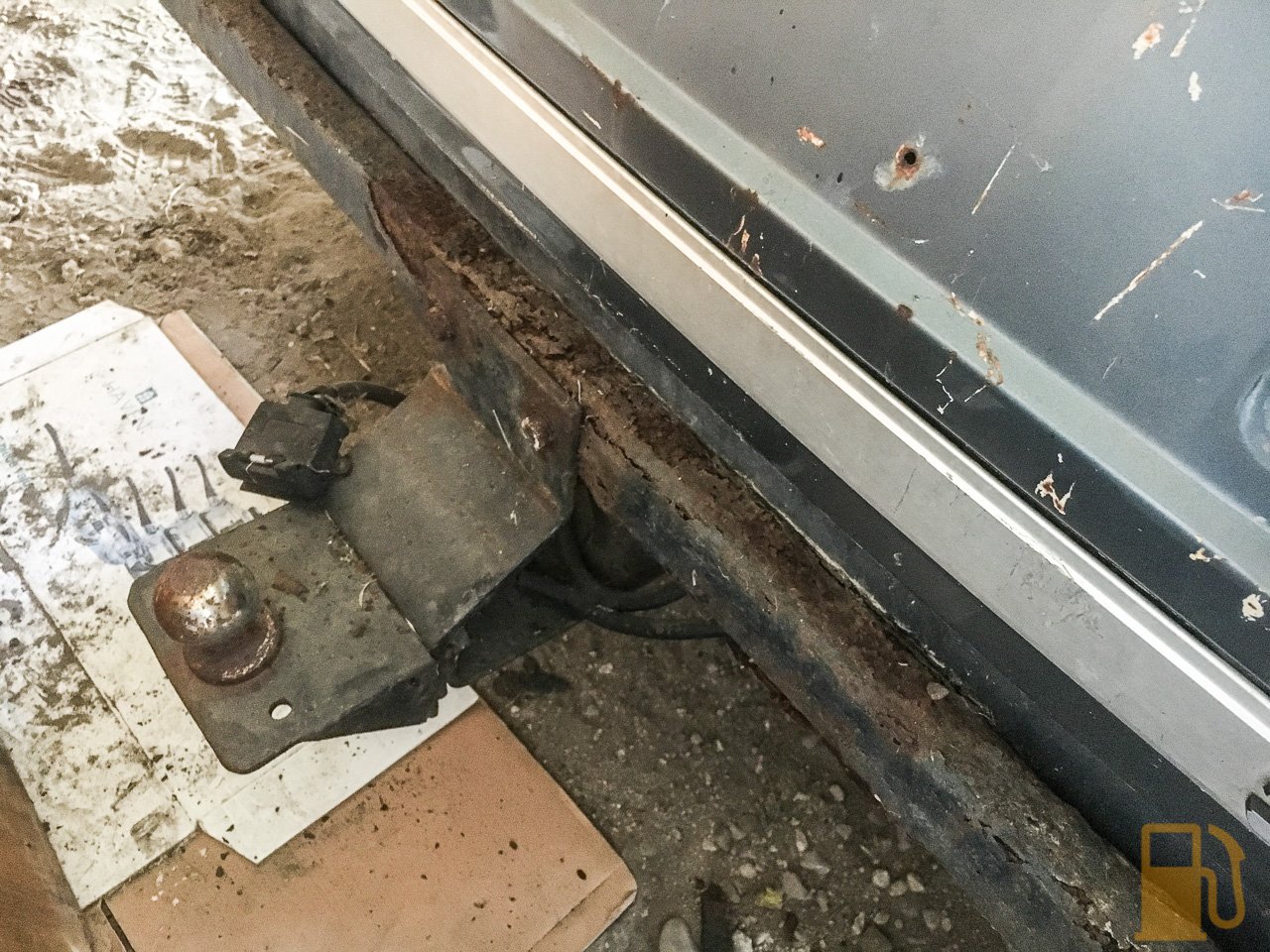
The blue car next to it was an 2600s, and other than no engine or box it was a mostly complete car. This car yielded some goodies, like a towbar which will be going on my SD1 shortly
It's not the most fancy or solidly built towbar, so I wont be towing car trailers with it or anything, but being able to haul a load of garden waste or a motorbike around would be awesome. Nothing like towing a mundane load with something special.
That car had the same colour interior as my car so I yoinked the center console to replace mine, which has a couple of holes drilled in the black plastic section
Don't work on cars that have been sitting outside on a farm if you can't man up and pretend there aren't spiders. This one was chilling out right next to where I was working in the boot. There was one on the other side too, of similar size.
There was also another almost complete 3500SE in the back shed
This one had some very terminal rust in the firewall, and had been off the road for about 10 years (and likely sat in the same spot all that time). It was also sans its v8 engine and manual gearbox
It was pretty dusty, and the tires ceased being round years ago
The interior was also full of various other cars interior bits and pieces
Nick took the bumper off this car, and I happened to notice how much you really wouldn't want to be towing with it! Very crusty.
I got a bunch of good stuff from that car, including some spare headlights, some good uncracked tail lights and a set of indicator/wiper stalks that aren't broken.
The shed itself was full of hidden goodies. You really needed to keep your eyes peeled as there was stuff everywhere. This straight through large bore exhaust was just chilling against the back wall. I had to strongly resist the urge to bring that home with me. Gosh it must sound good though.
Nick found a couple of good bumpers hung on the wall, and I almost lost my shit when I spotted something tucked away up on a shelf
Yes, that is a legit original rubber Vitesse spoiler. It's in terrible condition, but I will save it. These are like gold-fish teeth to get hold of, and here was one, sitting right there. *regains composure*
It's badly painted, cracking and the internal metal frame is rusting, but I'll sand all the paint off, remove what metal I can and see what I have. I'm hoping to be able to make a mould of it, and then either use the rubber one on the car, or make a light weight fibreglass copy and store the rubber one away. But hey, I have one, and that's what matters; It gives me options.
I salvaged a whole big box of other random parts, most of which I needed to tidy up little things on my car. I found a pair of these front chrome strips that go on the front grille (the one that my car had painted black, and I covered in chrome tape before British Car Day). It'll be nice to fit a proper one of these as the chrome tape looks good from far but far from good.
I also grabbed a speedo and tacho cluster. This has a good plastic lens to replace my scratched one, but more importantly it'll let me play with the trip counter and find out why they stick and won't reset, and how to fix it. I'll also look into the tacho and see what solder joints might have failed in mine so I can one day reinstate it.
I scored these two re-trimmed D-pillar covers too, to replace mine with all the fabric torn off them
I found a pair of these series one front corner lights too, so will experiment with swapping from the orange lenses to the clear lenses (the orange insert on these ones can be removed) and see if I like it. One is damaged, so if I like it i'll have to try to source a good lens.
So yeah, we spent the whole afternoon stripping as much off these cars as possible, stuffed it all in the van and set off
And that was the last we will see of these cars. Sadly they will be sent to scrap now, crushed and turned into Cherys (or Chinese MGs).
-
3
-
-
Love the carbon fibre tube hiding the wiring for the injectors. Thats a real nice little touch.
That engine is clean enough that you could sleep with it in your bed.
-
1
-
-
2 hours ago, Testament said:
more complete info which I think that stuff in the first post must have been got from. pity the link he quotes at the beginning for the original source appears to be broken
http://www.celicasupra.com/forums/showthread.php?65106-R154-motor-compatibility


Shipping carparts from the UK
in General Car Chat
Posted
Wait youshop does uk now?
rimmers and the likes charge like a wounded bull for freight even for small parts.
I would be keen as a bean for uk shipping but I’m flat broke so can’t even buy parts. Sad face.