

kws
-
Posts
4,175 -
Joined
-
Last visited
-
Days Won
5
Posts posted by kws
-
-
14 minutes ago, ajg193 said:
I'm sure you are already aware, but best practice is to start with both rods equal length and keep them equal. ie for more toe in wind both out
That is what the book says to do
I have NFI how it currently is

-
 2
2
-
-
- Popular Post
- Popular Post

-
21
-
On 01/11/2024 at 20:18, fuzzy-hair-man said:
As the original position of the steering wheel on the column and potentially the column to the rack? has been changed, I'd start by turning the steering wheel all the way one way then all the way to the other counting the turns as accurately as possible, return back half of these to centre the rack, often the tie rods are adjusted to the correct toe but the rack wasn't centred. Then I'd check the column to the indicator self canceling mechanism, the mini has a little T threaded into the side of the column, with the rack centred it should be midway between the plastic fingers on the indicator that cause the indicator to cancel, (indicator indexes into the outer column so it should only fit in one spot, but mine was deliberately sitting in the wrong spot so the indicators would work). Once all that's set I'd put the steering wheel so it faces straight ahead.
I didn't really get mine right till I'd done these steps but my mini had been completely apart.
I'm assuming the setup looks somewhat like the mini, but given BL was in peak cost saving mode it's probably a good assumption.
The ability to do a wheel alignment at home was great for me as I could tweak suspension settings without continually wasting money.
The marina, in my testing in Mexico, seems to be tracking bang on straight since the string alignment but yes I'll check lock to lock like you say and see where the rack is at.
The indicator cancelling in the Marina is done via the steering wheel which has tangs on the back which engage with a plastic collar in the column stalks. It's all the same thing though really.
Just ordered some fishing line, pretty keen to improve on the home alignment setup. It's a real handy tool to have. If I could afford and had the space, I'd love to have a 4 poster and alignment machine myself. I hate relying on others for things I could do.
-
1
-
-
Anyone got experience with VH44 remote boosters? I'm looking to add one to the Marina once it's on the road as unboosted brakes are a bit too... manly... for me. I see there are HEAPS of Chinese knockoff ones available, including from "reputable" classic car sellers locally, am I right in my thinking that I'd be better off getting a recon original one, than trust my life with a Chinese one? Or am I just being silly and it'll be fine?
like, there is this which I presume is just a Chinese one, https://classiccarparts.co.nz/brake-booster-servo-kit-remote-single-line-1-:-1.9-aftermarket-tt3949z?search=servo&description=true
And on the other end of the scale of Chinese ones, https://www.trademe.co.nz/a/motors/car-parts-accessories/parts-other-makes/brakes/listing/4985996566
CBC often lists original ones they have rebuilt, which come at a much higher cost, https://www.trademe.co.nz/a/motors/car-parts-accessories/other-accessories/listing/4986494157
-
3 hours ago, JustHarry said:
@kws something you mught find worth investing in is a scrub board. Its for setting toe as a dynamic measurement.
You drive across it and the top moves from the toe and shows a combined measurement. Often measured in feet per mile of sideways travel . Between 0 and 5 in is pretty good for most stuff.
They come up on trademe every now and again
I was looking into these, but they had very mixed reviews and pretty spendy
https://www.gunson.co.uk/product/G4008/Trakrite-Wheel-Alignment-Gauge
-
- Popular Post
- Popular Post
It'll come as no surprise that I've paid for a lot of alignments in my time, and as on most cars they can only really adjust toe, it began to irk me how little value I got for my money.
With that in mind, there is one thing I have wanted to try for a long time but never really been bothered to do, as it seemed like too much work. A DIY string alignment.
I will say off the bat, I know it won't be as accurate as frickin lasers on a machine worth tens of thousands of dollars, and adjusting the toe without a hoist is a pain, but for the cost of... almost free, it's good enough.
I had done a lot of research and even considered spending the money on a pair of nice toe plates that you use with a pair of tape measures to check if the wheels are toed in or out, but the idea that it couldn't identify if the wheels were "straight" but actually both pointed off to the same direction, didn't sit well with me.

And then I found this guy's video online, and it seemed just easy enough that even I could make a string alignment work
The basic theory is that you run a pair of string lines down the sides of the car. With certain measurements, you make the string lines parallel and then measure the distance of the front and rear edges of the wheels against the string to check toe. This method will only do toe, but that's all I need to measure.
Having just done work on the steering of the Marina, and it being decades since it's probably seen anything resembling an alignment, I wanted to check it before I went too far on the road again.
Years ago I marked the steering column before removing the steering wheel, and when I last refitted it I fitted it to the marks, which meant the wheel was off center for whatever reason (maybe wasn't straight in the first place). I fixed this by just moving the wheel a few splines over, and it was close enough. Before checking the alignment now, I foolishly moved the steering wheel back to the marks, thinking it would be a good idea.
In an ideal world, you would center the rack, center the steering wheel and then do the alignment, but I don't have a centering hole in the rack as the UK cars do, and I didn't want to have to measure tie rods, so this is close enough.
I fired the car up, and using its freshly rebuilt clutch slave, moved it back up and down the driveway a few times to settle the suspension.
Before setting up, always roll the car forward, not backwards, as this can impact the alignment settings.
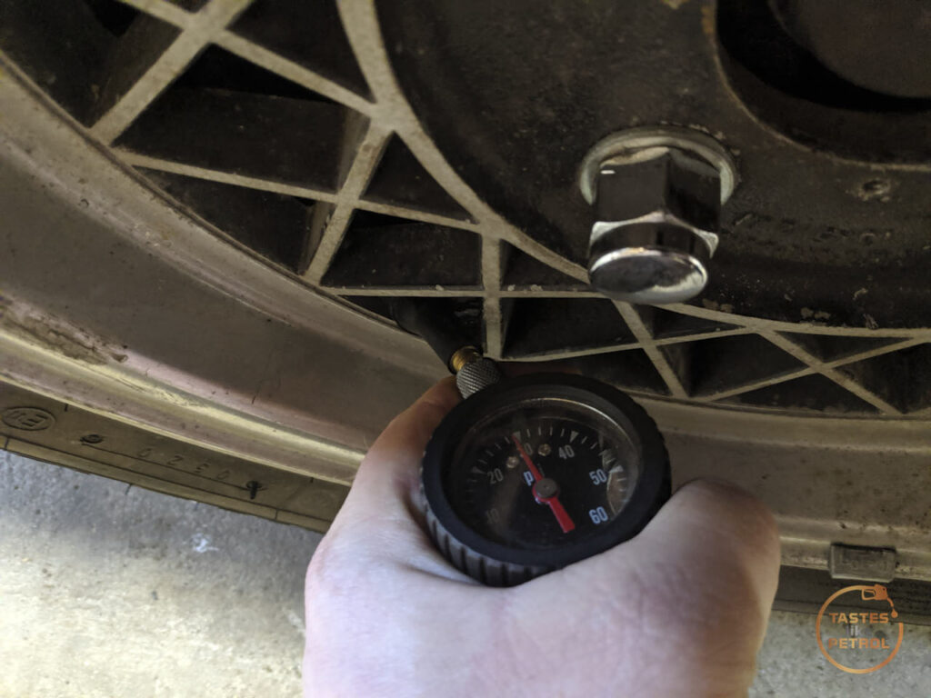
Next, I checked and set all the tire pressures to the same 28-29psi
Then I set up the string lines on my four axle stands. Almost immediately I noted that the string I was using wasn't right, it was too thick and "fluffy", you really need something like fishing line for this, so it's thin and accurate. Regardless, all I needed was a ballpark figure, so I pushed on.
I pulled the string quite tight by rotating the axle stand
The first hurdle for me was that I don't have center caps, just a big gaping hole. That makes it a bit harder to measure from the center, so after a few tries of different things, to set the string height I settled on my camber gauge with its top edge sitting at the center of the hub and the bubble flat. The height doesn't have to be 100% accurate, just close enough to the same for both wheels on that side. The string height is set by moving the center of the stand up and down for coarse adjustment, and then sliding the string up and down on the stand for fine adjustment.
Next was to measure the distance from the center of the wheel to the string. You need to factor in the track width of the car with this, so that the strings are straight and not slightly tapering off, as the front and rear track are not usually the same.
In the Marinas case, the track is 1333.5mm in the front, and slightly narrower 1331mm in the rear. I wanted the string to be 80mm from the rear wheels, so I measured that from just in front of the center bore, at the height of the string.
Ignore the .45mm extra, it's really hard to be accurate when also taking a photo.
Because the front is slightly wider, I needed to remove the extra width from my measurement, which is 2.5mm across both sides. Halve that, and you get 1.25mm per side. So I needed my string line to be 78.75mm from the wheel on the front. Moving the stands at the front and rear until I got those two measurements, on both sides of the car, and I finally had a pair of parallel strings. Not too hard!
Now it was time to measure the toe. I used my calipers on the wheel lip to check the distance to the string line. Protip, make sure your wheel weights aren't in the way...
Having checked both sides, I knew the rear was square as the front and rear measurements were the same (good test of my string lines), but being a solid axle I expected that. The fronts, well...
The numbers were messing with my head a little, but from that I had 11mm of toe, but not in or out, they were pointing off to one side. They were pretty well parallel, but not straight. This is where the string line has an advantage over the toe plates, it can tell me the wheels are pointing off to the side but only had 1mm toe difference, the plates would tell me there was 1mm toe but not that they are pointing off to one side.
This was due to me moving the steering wheel on the splines. Darn.
I straightened the steering out so the wheels were more or less straight and then moved the steering wheel over on the splines to straighten that out. To settle the steering I had to push the car back and forth again, which meant the poor thing got its tail out in the rain. With the faint sounds of rust creeping in, I rolled the car forward and set up again. This time all I needed to do was set the string the pre-measured distance from the wheels again
Round two was a lot better, this time it looks like I'm slightly pointing off to one side
It appears I have about 1mm of toe in on one side, and I'm pointing off to one side still. I need to drive the car and see how centered the steering wheel is, I suspect it might need to go over one more spline, but since it hasn't really stopped raining, I won't be venturing out just yet. Once I have the steering wheel centered, and the car tracks straight, I'll get some fishing line, set up again and see how the actual toe is. The setting in the book is 1.6mm combined or 0.8mm per side toe in (wheels closer together at the front edge than the rear).
Over all, the string method seems pretty good. It'll suck to have to actually adjust anything since any time you move the car, move the strings or make any changes you need to set things up again, but you can probably get fairly quick at it with some practice.
I'll play with it more, on my other cars too, as a quick basic way to make sure the toe isn't wildly out before having someone check it properly on a machine (if needed). I wouldn't bother with a machine alignment on this Marina, since there are no more adjustments than toe, and this isn't a daily driver, as long as it's in the ballpark and drives straight, I'm happy. My daily, or track car, should really be checked properly for handling and tyre life reasons.
I can definitely recommend giving it a go, it's a fun skill to learn and pretty low cost if you have some measurement tools, a set of four jack stands (or similar things to tie the string to on each corner), some fishing line and some time.
-
24
-
 1
1
-
- Popular Post
- Popular Post
Along with the underside tidy-up that I did in the last update, there were a few mechanical bits I needed to deal with before the next inspection in a couple of weeks.
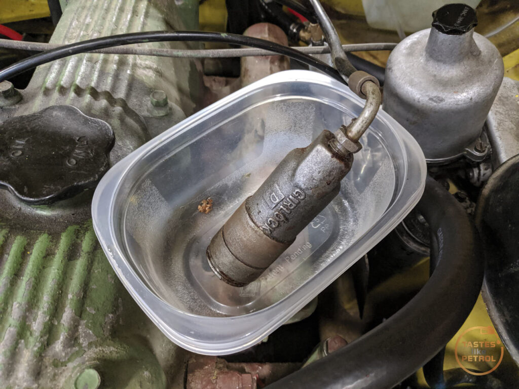
The first one was an annoying one; the leaking clutch slave cylinder.
I knew the cylinder was slowly weeping fluid, and it appeared to be from the bleed valve. I wasn't too worried as it seemed to lose fluid quite slowly, and I planned to deal with it later.
Unfortunately, on top of all the other things the WOF guy blasted me on, one of them was the damn slave cylinder taking a dump. It was still working fine (despite him using it as a reason for grinding it into reverse, nah mate), but it was actively leaking fluid out the front of the cylinder and down the bellhousing now. Balls.
I was particularly annoyed by this, not just because it was one more thing the WOF guy didn't like, but because I had already rebuilt it. I sent it out to be resleeved in stainless and I fitted a seal kit I got from the UK.
This time I didn't bother to strip it, I decided I would have the pros strip and rekit it for me, just in case there were other issues at play.
The culprit lurks down here. In hindsight I should've painted it after it was sleeved (came back freshly sandblasted)
It'd used half the reservoir of fluid just in the test driving before the WOF, and the drive to and from the workshop
I removed the pushrod, boot and retaining circlip. The boot was full of fluid
With the circlip removed the cylinder just slides backwards out of its retaining ring on the bellhousing, making it a lot easier to disconnect the pipe
A big adjustable spanner is used to hold it whilst the pipe is undone
I was recommended these pipe-end blocking clamp things by a friend, and I'll be darned if they aren't pretty handy. Normally I'd just tie a rubber glove finger over the end and deal with a glove finger full of brake fluid later, but this sealed it completely with no mess
The inside of the cylinder wasn't looking too hot (and the piston was stuck at the bottom...)
And some very fine marking on the bore
I sent it off to the guys that sleeved it originally, CBC Brakes down in Christchurch, and this is what they came back with
The seal had rolled in the bore. I honestly don't know how that happened, or when it happened. I had no issues fitting the piston, it didn't catch, and for it to have even been working as it was is a miracle.
Either way, despite my embarrassment at having cocked it up and with only myself to blame, I had them rekit the cylinder with a new seal.
I will say, CBC have been awesome every time I have dealt with them. Their turnaround is super quick, they are reasonably priced and the work they do is faultless. Now I've had them resleeve and kit the brake master, clutch master and clutch slave. I'm glad I had them do the brake master, I wouldn't want to find out I rolled a seal in that! No room for failure with a single-circuit brake system.
The slave cylinder arrived back in record time, and I think they took pity on me because this time it came freshly painted and looking a million bucks.
I quickly set about refitting the slave. I greased the end of the pushrod and refitted it into the boot
The pipe was refitted, and the slave was slipped down into its retainer and the circlip refitted. A few pumps of the hand vacuum bleeder got fluid flowing, and I finished it off with the trusty one-man bleeder bottle.
As an aside, when refitting, despite how much of a pain it is to have the feed pipe on the bottom and blocking the bleeder, the bleeder must be fitted at the top or you'll never bleed the air out.
In my testing since refitting, the clutch feels much the same, which I guess is good. No leaks though, so I'll take that as a win and having it properly rebuilt now, hopefully I'll never have to look at it again.
Now, two big things were picked up on in the "WOF" check. The RH rear wheel bearing was grinding, and there was play in the steering.
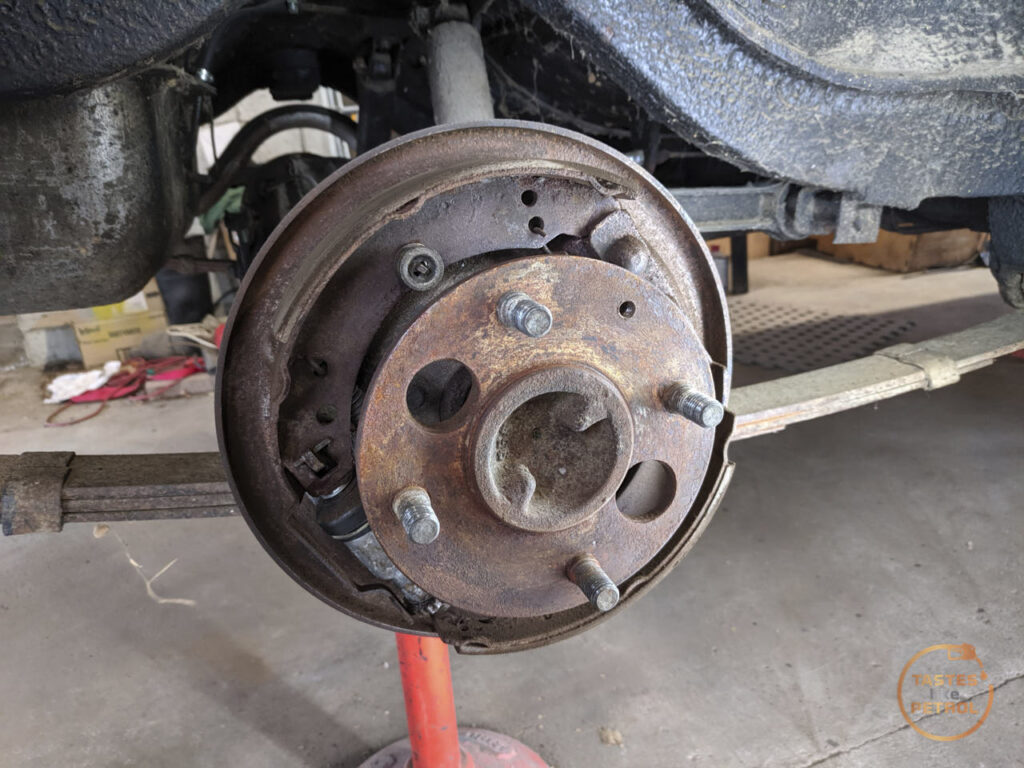
I started with the wheel bearing. When spinning the wheel there was a definite whirr noise, which wasn't present on the LH side. I watched a couple of videos on Youtube, and ordered a new bearing kit.
Do note that as my car is an Aus Marina it uses a Borg Warner rear axle, so the work I've done may not apply to UK cars, but I imagine the theory is similar.
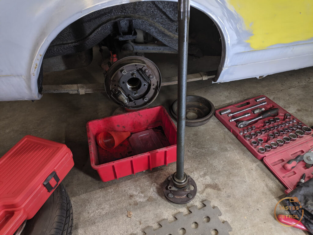
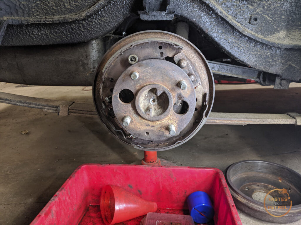
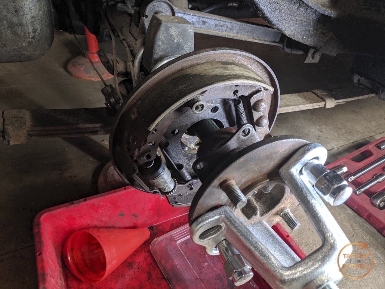
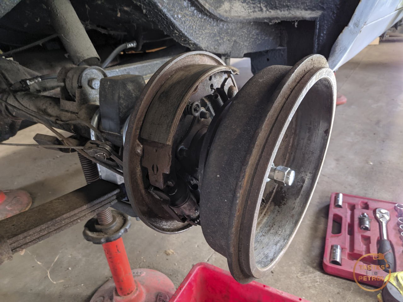
The drum has to be removed first, which exposes the axle
Four nuts secure the retaining plate
These are accessed via the big cut-outs in the face of the hub flange
With those four nuts removed, the axle should pull free from the diff. Should.
Most people say to flip the drum over and secure it with a couple of wheel nuts wound on a couple of threads, and use it like a slide hammer to thump the axle free
This did not work, despite many many attempts. It got to a point where either I was going to pull the car off the axle stands, or break the drum, neither of which I wanted to do.
I got pretty annoyed at this point, and after all my efforts I had only moved the bearing maybe 1mm as I could just see a lip of rusty bearing showing.
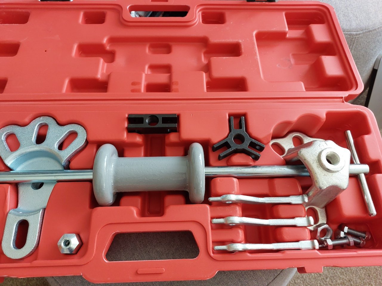
A new plan was needed, so I bit the bullet and ordered a slider hammer kit that included the required fittings for axle removal.
In the meantime, I took a look at the play in the steering.
The Marina has a fairly well-known issue where the inner rack support bush on the LH side wears out, as it's made of nylon, and this allows for play in the inner rack. Because the rack can physically move up and down, this allows for play in the LH wheel.
I checked for play when I first got the car, and I don't remember there being any, but I ordered a new bush anyway and put it into my spares. Now though, it's good I did, because when you wiggle the wheel side to side, heaps of movement.
It is recommended to remove the rack, strip it down completely and then bash the old bush out from the other end. There are a few that have done it on the car though, and as I'm low on time and can't be bothered removing the rack, I chose to do it on the car.
Before doing anything else, crack the tie rod end lock nut, as you'll need to remove the tie rod end and this can be properly stuck. With that free, remove the nut on the tie rod end and pop the taper using a couple of whacks of a hammer on the arm.
Counting the turns, wind the tie rod end off
Remove the lock nut, and after loosening both clamps, remove the boot. Be aware it should be quite oily.
Interestingly the inner tie rod is actually serviceable and adjustable using a cup and spring setup
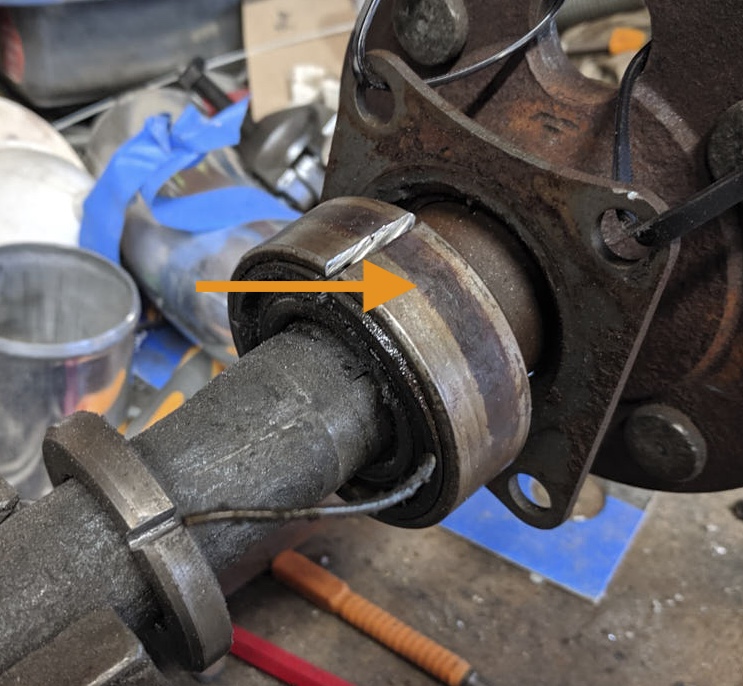
As a note, the worn bush is #12 and retained with #11 screw
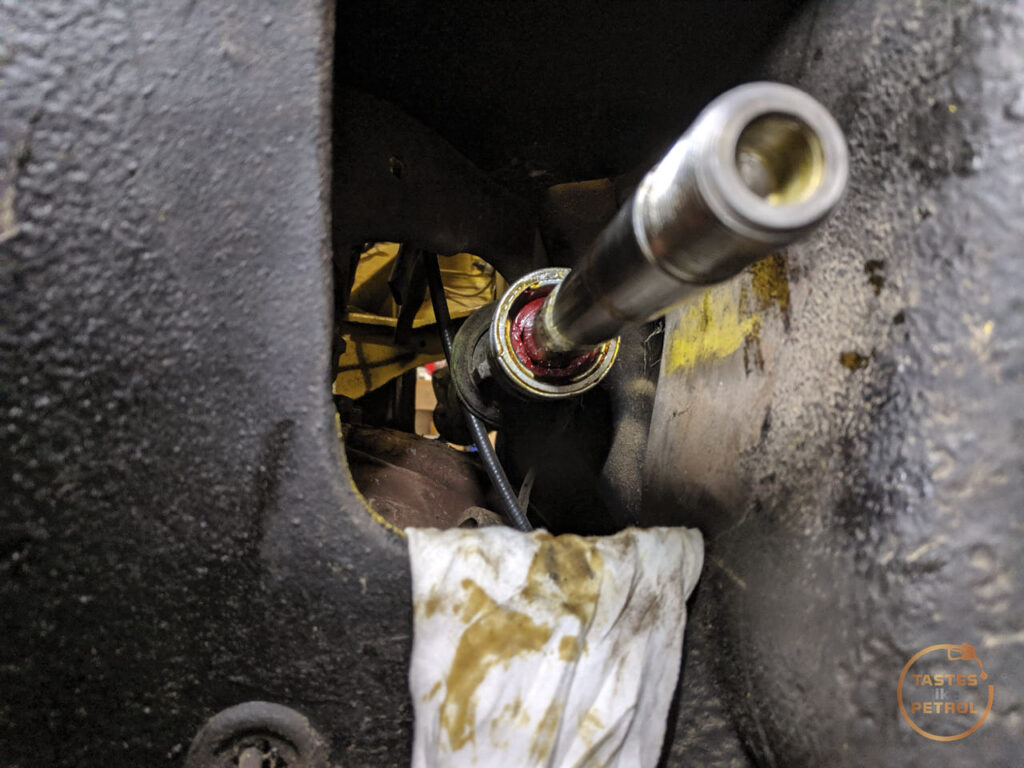
The rack end is locked in place with #10 "locknut", which uses a stake on each end to lock both the tie rod and the rack end together so it can't come loose. I used my big grips on #8 "ball housing" wiggling it back and forth until the stake on the rack end loosened up, and then I could wind both the housing and locknut off. In the end of the tie rod is the cup and spring. Once on the ground I could separate the locknut from the housing.
With the tie rod out of the way, you can see the worn-out bush. Theres nothing touching the rack
The new bush is made by Nolathane in polyurethane and is part number 41044.
I slid this over the end of the rack, and carefully drifted it into place against the old bushing. Before fitting I measured how deep in the rack the original bush was, and how long the new bush was, so I knew it was fully seated.
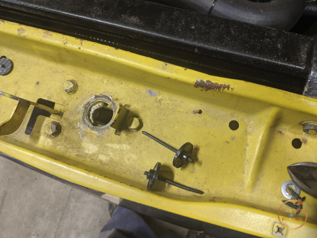
The one catch is that if you aren't removing the stock bush, you need a new screw in the housing to retain the new bush. To do this you need to drill into the housing and screw in a self-tapping screw. I did this in the bottom of the housing as it was easiest for me to access, but in hindsight, I would fit it higher as I have had to use sealant to stop any oil leaking passed the screw.
I couldn't find it at the time and only later noticed it in the photo, but the screw retaining the original bushing is there, with the orange arrow. The new screw I fitted is the green arrow. Looking at where the original screw is, I don't think you could access it on the car.
If the bush comes loose, the worst that'll happen is that it'll stop supporting the rack and it'll be no worse than it was before, since the old bush is still there. If that happens I will remove the rack and fit the new bush properly.
The instructions to fit the tie rod are fairly specific. First screw the lock nut onto the rack and bottom out the threads. Before I did this I used some narrow pliers to straighten out the stakes.
Next, you insert the spring and then the cup, followed by the tie rod and its housing. Screw the housing down until the tie rod is nipped up and cant swivel, and back off 1/8 of a turn until the tie rod can articulate fully but still be firm (the spec is 3.63-4.18nm of force to move). Next wind the locking nut into place and lock it with the tie rod, making sure the adjustment is still in spec.
Now, using a punch, lock the nut to the housing, and the nut to the rack, both of them have indents where the locking gets punched into
Now slip the boot back on, do the clamps up, refit the lock nut and tie rod end (turning it the same amount of turns it came off). Refit the tie rod end to the arm, and its job done.
I haven't driven the car since, but there is no play in the wheel when wiggling it side to side, and it was really obvious before.
It will be interesting to know how the steering feels now. It's always been a bit vague and wandered a bit, it'd make sense since it had dynamic toe on the LH side.
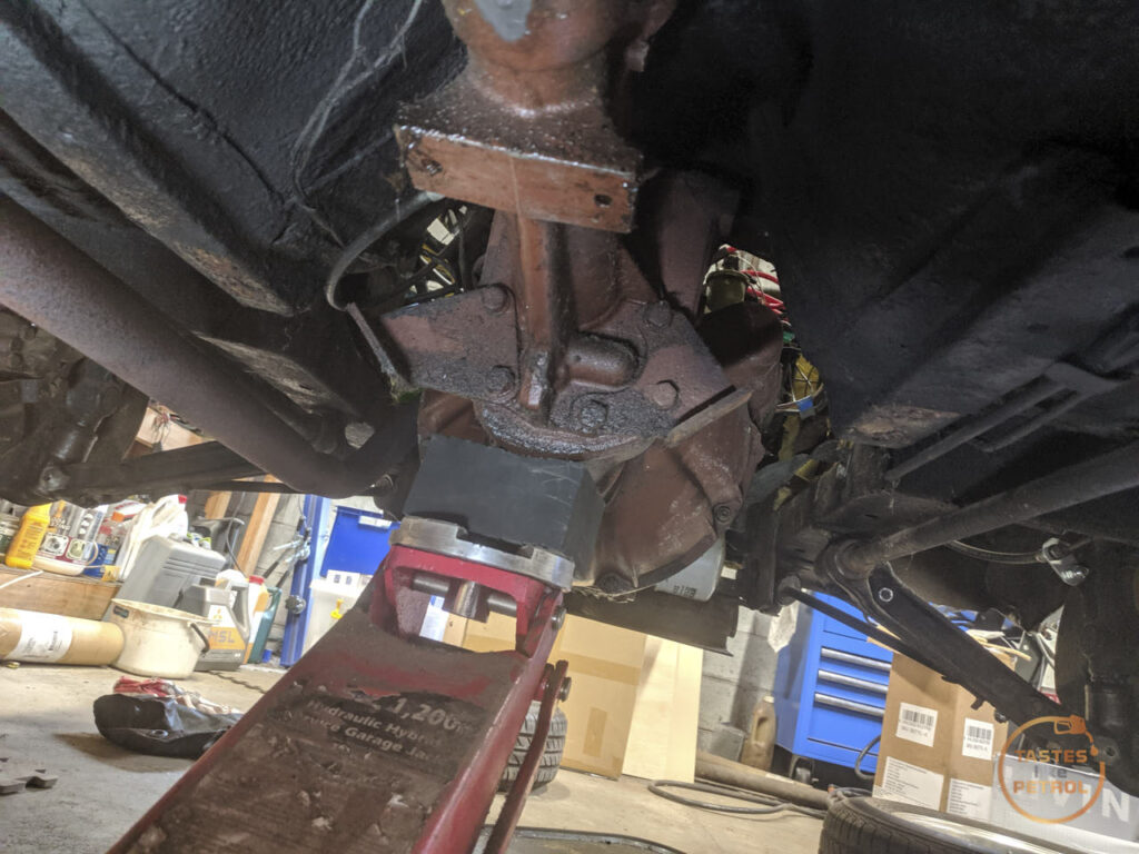
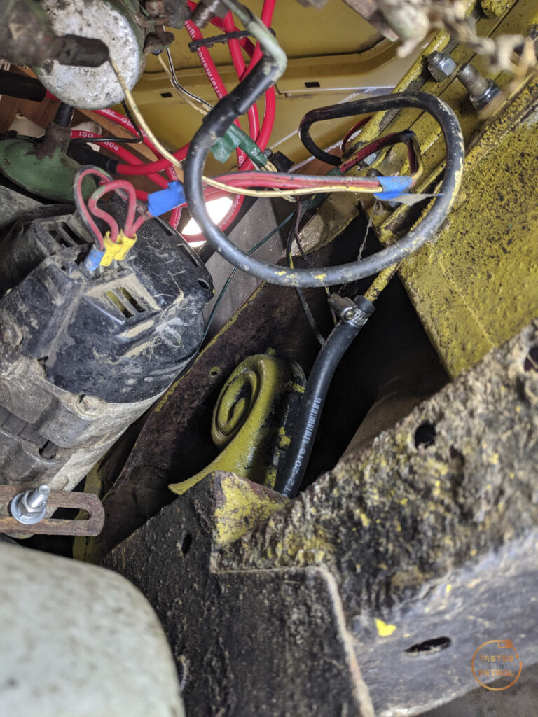
While waiting for the slide hammer to arrive so I could yeet the axle out of its home, I ordered a couple of transmission mounts, which arrived quickly.
I did a bunch of research around these because original mounts are NLA, and the Aus cars use a completely different mount setup than the UK cars.
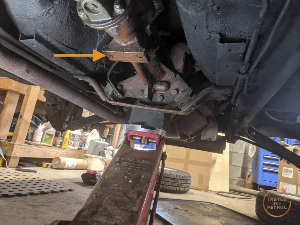
On the UK cars they use a cross-member mounted to the body, and a single rubber mount the gearbox rests on. This mount is attached to the very end of the tail housing on the gearbox, Whilst the Aus cars have a pair of mounts much further forward on the gearbox on a pair of plates and brackets
The orange arrow points to where the UK mount would be on the gearbox
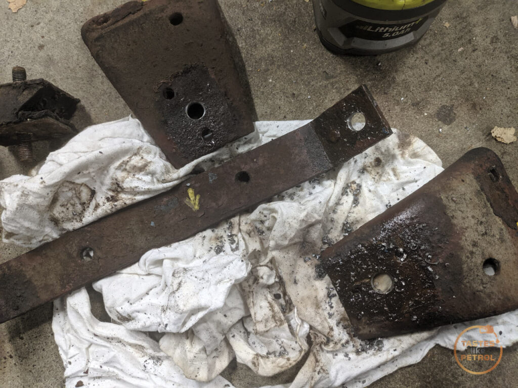
The stock mounts are a weird Z shaped thing, and mine were trashed.
I had an idea I could probably find a cotton reel style mount that would work, and after much digging around the internet I found someone on the Aus Facebook group mention they had successfully used "series Land Rover gearbox mounts". Some more digging, and I came up with a local supplier of NRC2054
Compared to the original mounts they're a bit taller, but I have no idea how compressed those old ones are
Getting to that point wasn't too hard, I supported the gearbox on the jack and removed the bolts for the "cross-member" which is actually two brackets linked by a brace. This allowed the mounts to slide out
The new mounts are metric 10mm studs, so I had to drill out the smaller imperial holes to fit, both on the chassis brackets and on the gearbox brackets (that was fun...).
What came next was like trying to assemble a jigsaw with only a vague picture, and a bunch of bits that don't fit together. It sucked.
Because the mounts are on an angle, everything has to slot together nicely in a certain pattern, and nothing fit. I ended up having to remove most of the bolts from the brackets on the gearbox, so I could pivot them around, and jack the gearbox up and down
Everything had to remain super loose until eventually it all fell into place, all the bolts went in, and only then could I tighten them all down. Some use of the big lever was needed.
Paint marks because ADHD life
The gearbox definitely sits a little higher now, this was most obvious by the fact that the top radiator house was now firmly trying to occupy the space the radiator fan does. They've always had a slightly touchy-feely relationship, but this was beyond acceptable.
I had preempted this, by buying another radiator fan mounting kit. I wanted to move the fan over to give the hose more space anyway (I mounted the fan to the radiator out of the car, before I had fitted the top hose and realised the fan cannot be central on the radiator), so this was my chance.
I snapped all the little ties off, using a metal trim tool on the fan side to gently twist it back and forth until the head popped off
I moved the fan over and gave everything some nice clearance and zipped it into place
Ample space
Technically it's on the hotter side of the radiator now, so maybe it'll work more efficiently.
Finally, the slide hammer arrived (to be fair, it arrived after the weekend. This work all happened over the course of a couple of days)
I ain't playing around now. I tried asking nicely.
I attached the fitting to the hub
And screwed the hammer into it
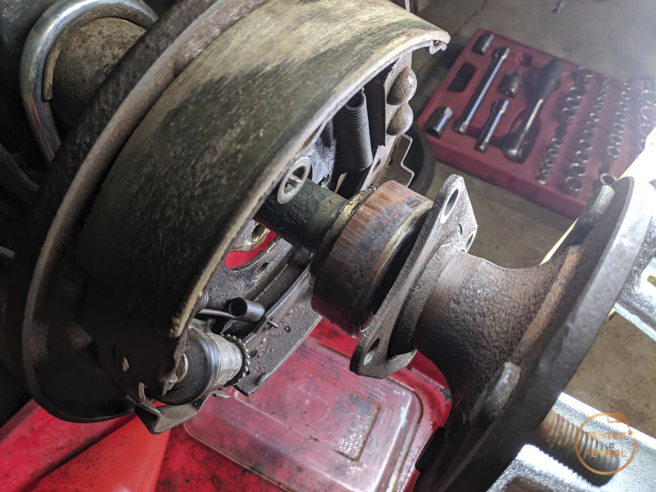
Three decent thumps, and the axle was out. It's amazing what you can do with the right tools.
Forget Loctite, rust is the best bearing retainer
I pulled the axle out and cleaned the oil off it
It's not really any surprise I needed a slide hammer to remove it, the manual does call for special tool 18G A284 "impulse extractor", which looks suspiciously like a homemade slide hammer.
To say it needed replacement might be an understatement
To actually replace the bearing you either need to press it and its retaining collar off, or just do what everyone does and cut them off.
I stuck the axle in my vice and zip-tied the retaining plate away so I had less chance of cutting that off by accident
I fired up the death wheel and got cutting. The retaining ring was first to go
Once it was cut most of the way through I stuck a chisel in the cut and a couple of hits split the metal and it slid right off
The same happened to the bearing. I cut through the outer race in two places and broke it away
I removed the balls and inner cage and then cut into the inner race. Once again, when I was mostly through it I smacked it off with a chisel
You can see here I only needed to cut so much of it before the chisel just forcefully cracked the rest of the way. It only took a couple of hits to split. Also note the dull grey area to the left of the cut, this is the reason you must wear PPE doing this, as that's where a chip of steel must've broken off and flown off at high velocity. You don't want that in your eye.
Strangely the races of the bearing seemed pretty ok considering. This was the worst damage I could find; a couple of marks on the inner race
It's interesting to note though that you can see where the bearings run on the outer race, it must've gotten hot?
With both bits loose I removed the axle from the vice and shook them free. Now it was time to fit the nice new one
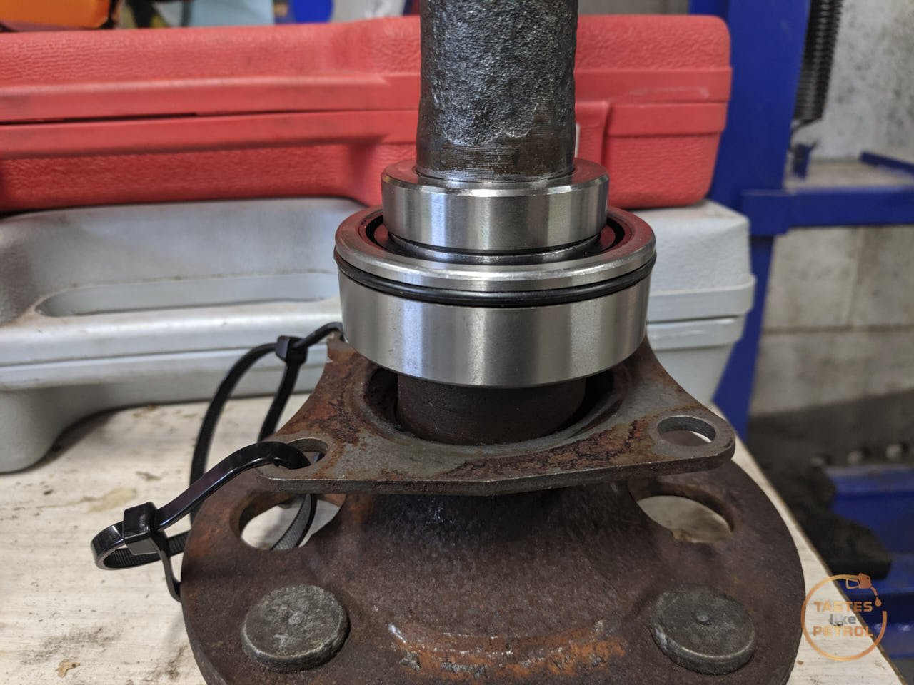
The kit comes with the bearing and a new retaining ring. Do note when fitting these that the bearing has a raised lip on one side (facing up in the above photo), this must face the hub flange when fitted
Making sure the retaining plate was in place, I carefully slid the new bearing onto the axle and mounted the axle into the press. I'm using the old retaining ring to press the bearing on, as it will only exert force on the inner race of the bearing, and having been cut it won't bind on the axle shaft. My biggest socket gives the press a flat surface to work off (slightly bigger would've been nice so it could sit on the ring not just the raised bits in the middle, but it's not often I'd need bigger than 36mm)
Here's the old retaining collar being put into use
I slowly pressed the bearing on until it bottomed out
With the bearing in place I slid the old ring off, and the new ring on. The old ring was then used to press the new ring on
And done
The bearing spun smoothly by hand, albeit with some resistance from the grease inside the bearing
I gave the housing a good clean up with a scotch pad to remove any rust that might stop it sealing. It was pretty manky
I don't know if it's right or wrong, but I read others have done it, so decided to use a very thin smear of sealant on the surface the outer O-ring seals on. The old bearing was the type that is just a friction fit, but this type relies on that O-ring to keep the diff oil where it needs to be (along with the bearing being sealed).
I carefully slid the axle through the backing plate and into its home. I gave the hub flange a couple of hits with the soft face hammer to make sure it was seated.
With the four nuts tightened down on the retaining plate, the drum went back on
Finally, the wheels were refitted. Before lowering to the ground I spun the wheel and noticed it had a noticeable rumble when spun. Asking around, it appears this is normal for new sealed bearings due to the grease in them, and even bearing manufacturer SKF suggests running the bearings for a few km (or 10 minutes) for the grease to break in, so I'll give it some time and check back later and make sure it's all working as it should.
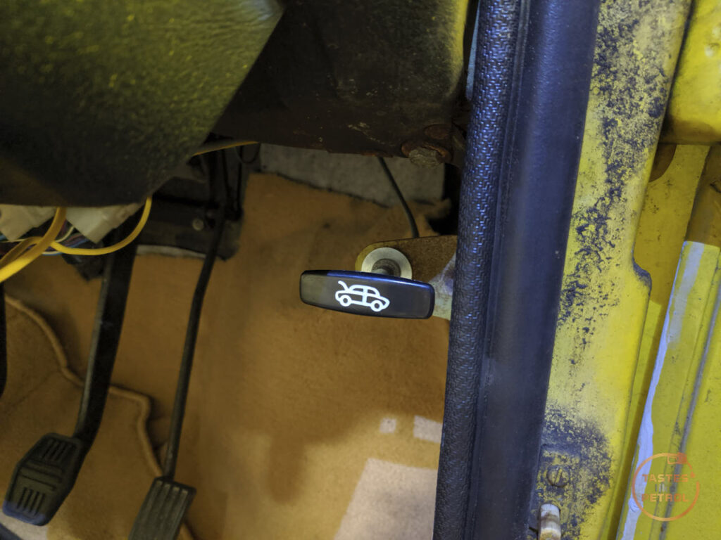
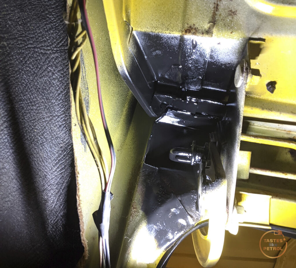
Once on the ground, there was one last job on my list and that was to replace the bonnet cable. The old one was really stiff to pull, and half the T handle was broken off, risking the other half breaking off and being a pain to open.
Doing some googling around it seemed like the MGB bonnet cable was able to be used, so I ordered a CHA460
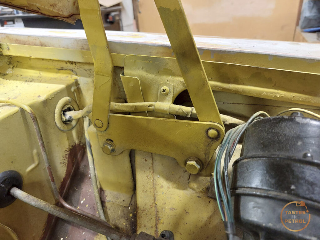
To remove the old cable I had to remove the front grille, and that gave me access to the cable and bonnet catch. The cable loops through the release lever and is then secured in that little screw thing. The cable outer is secured in a clip on a bracket to the left
I undid the cable and removed the clip, allowing me to remove the cable
I undid the nut holding the handle in place and pulled the cable through the car. Refitting the new cable is just a case of putting the cable through the bracket, securing the handle with the nut, and running the cable through the engine bay to the bonnet catch. The new handle body is a bit smaller than the old one so I used an appropriately sized washer to make it fit better
Unfortunately the CHA460 is too short. The cable inner just makes it and can be secured in place, but the outer has no chance of being clipped in place. From my measurements the outer needs to be about 155cm long and the inner 160cm or so.
The cable works as it is, and works really well, the bonnet is much easier and nicer to open, but I need to secure the outer, maybe with a clip or just a zip-tie to that hole there.
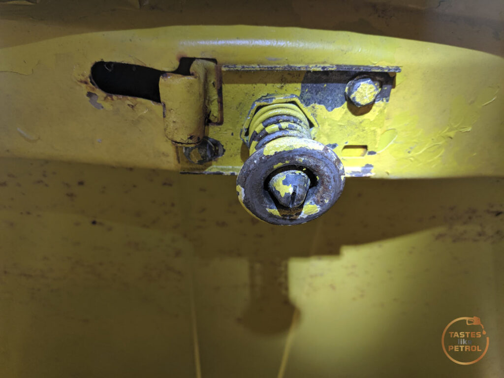
While in the area I finally took some time to adjust the bonnet properly. It's always sat a bit off, and I've had issues with the bonnet popping when driving, which led to some bodges to make it work before the last WOF check.
I undid the bodges and found the adjustment slot in the end of the catch pin was so full of gunk you couldn't see it at all, so after some digging it out, I could adjust it properly.
To free the center pin up, I removed the catch and put it in the vice. Using my rattlegun with a slotted screwdriver bit, I gave it a quick jab of the button, which instantly freed the pin up.
I refitted the catch and adjusted the pin to the spec in the book; A= 50.8mm
I had to wind it out significantly to get that measurement, it was at least 10-15mm too short.
I used the slotted adjustment holes in the catch to move the bonnet left or right when closed, and get the gaps nice. After some playing with the hinge adjustments
Along with the little rubber bumpers
I was finally happy with how the bonnet shut. It sits a little high in the middle at the back due to the seal, so I'll need to look into that, but otherwise it's good.
That's pretty much the car buttoned up again and ready to go. I did do a string alignment to check how the toe was, but I'll do a write up on that later as this post is already getting too long.
I'm two weeks out from my next inspection, which I've specifically booked as a "pre-WOF" inspection, or a WOF that won't be entered into the system if it fails, just in case. Surely I'm running out of things that it can fail on?
-
18
-
2
-
25 minutes ago, tortron said:
Tldr. They come with "gritty" feeling grease, Let it bed in for a few thousand revolutions
Thank you, I obviously wasn't searching for the right thing.
I've done a couple of sealed wheel bearings as an assembly and they have been stiff but not rough like this, so presumed it was bad.
Will leave it for now and put some ks on it and check again.
-
2
-
-
So, having just replaced the RH rear wheel bearing on the Marina, because there was a definite rumbling noise/feel from it, the noise/feel is still there.
The old bearing was bad, it was hard to turn/crunchy once removed, and the grease in it was gross. There were a couple of small marks on the bearing race, but not as bad as I expected. The new bearing spun smoothly in the hand, although with a fair bit of resistance (which i presume is the grease in the sealed bearing).
The LH side wheel spins smoothly and silently.
Any thoughts? I was thinking maybe it's a diff bearing, but having spun the wheel with my head near the diff center i can't hear it from there, it's only really noticeable from the wheel end. Could it be a bad, brand new bearing? Pressing it on went fine, I used the old steel retaining collar to only put force on the center of the bearing, not the outer. Once the bearing was "home" I didn't exert more force on it.
-
1
-
-
I bought one of these a couple of years ago, thinking it'd be handy https://www.machineryhouse.co.nz/s648
I've barely used it and regret spending all that money on it (should've got shrinker/stretchers instead). The pressbrake has been handy once or twice, but it's nothing i haven't been able to do in my vice with a hammer, quicker and with less setup. The guillotine can only cut pretty thin steel, unless you strip the whole thing and set it up properly it struggles with 1mm. The rolls work, but ive only needed it once.
Theres a couple of good videos on youtube about them and how when you get them you MUST strip them down completely and rebuild them, as the assembly and tolerances they come with from factory are terrible and it'll struggle to give any results let along good ones
I should probably look at just selling it, actually.
-
1
-
-
Thats very cool, even with the NFS Underground bodykit on it. Love a good FD, one of the most beautiful cars ever designed IMO.
Hopefully the dorito spinner keeps working well. Do you know the origin of all the rusty shit everywhere, hopefully just the coolant tank?
-
2
-
-
2 minutes ago, Goat said:
More panel repair questions, What do people find more useful for making rust repair panels, a sheet metal brake, or a shrinker/stretcher?
I have neither and made do, but did think in hindsight that a shrinker/stretcher would've been handy for curves like wheel arches
-
1
-
-
2 minutes ago, Nominal said:
Pity they 'upgraded' Minor diff which has separate hubs and bearings from the axles
")
Needed the beefy BW diff upgrade for the power from the super advanced OHC 1750 lump
-
2
-
 2
2
-
-
5 hours ago, Tiger Tamer said:
I am interested in this. I need to do the Avenger diff rear axle bearings as well. Never done it before so it would be good to hear any tips. Also any trouble getting the correct wheel bearings ?.
I'm not sure if the Avenger has the same style bearing, but I think they're much of a muchness. I haven't finished the job yet, i still need to replace the bearings, but I've been following this video as the setup on his Capri is the same as my Borg Warner diff
I got the bearing kit from Mytools on trademe, which sells the ABD kits https://www.abdgroup.co.nz/?action=autoinfo im quite lucky they do both front and rear bearing kits for the Aus Marina, for some reason.
-
1
-
1
-
-
- Popular Post
- Popular Post
It's amazing what happens when you have the right tools.
Also, fuck Loctite, rust is the best bearing retainer compound.
-
12
-
1
-
Regarding rust work tools;
I have a set of decent snips, and basically never used them for the bodywork I did. They are a pain to use, and thin/bend/curl the edges of the metal. I much preferred to just use a thin cutoff wheel.
For my power file, which I can also agree is very handy, I got one of these as recommended in another thread on there somewhere, https://www.thetoolshed.co.nz/product/3433-toolshed-file-sander and some green belts from Aliexpress (which way outlast the toolshed black belts)
and for the body saw I used, it was just a cheapie from Supercheap, and it cut through sheetmetal like butter. https://www.supercheapauto.co.nz/p/blackridge-blackridge-air-body-saw/572837.html#q=body saw&lang=en_NZ&vid=cMJ9mxC5VJn1zET7zKHliw%3D%3D&start=2 It aint perfect, but its cheap and does the job.
-
2
-
-
- Popular Post
10 hours ago, 87creepin said:@kws maybe try this https://www.mitre10.co.nz/shop/gasmate-multi-purpose-blow-torch/p/387804?store=88&gad_source=1&gclid=Cj0KCQjw99e4BhDiARIsAISE7P_ISar7sPpxDHBRl2oWzwWwEeZWgfqWV0AzmjvhIZL-6TDz-3ntjB4aAoWZEALw_wcB&gclsrc=aw.ds
and a bottle of butane
a lot of heat, followed by crc and your slide hammer should work
I won't be asking nicely this weekend, its hammer time
-
10
-
2 hours ago, cletus said:
can you get a map torch or similar on the bearing housing, give it a bit of a warm up see if that helps
I dont have fire, but i tried heating the housing up with my heat gun. Got it hot enough i couldnt touch it, but didnt help.
1 hour ago, shrike said:Rear bearings right? might be time to think about dropping the whole diff out?
Want to post some pics/video and is it one side or both?
Could you seal the diff housing and try pop it out with compressed air? (id have something to stop it from firing out)
Yeah Borg Warner solid rear axle. Access isn't an issue on the car, it's just stuck in there and the drum method isn't giving me enough thump. Slide hammer should be here tomorrow, so hopefully that frees it from its home. The Leyland manual does say to use "special tool impulse extractor 18GA284" or slide hammer for short.
-
3
-
-
1 hour ago, Adoom said:
You have definitely removed ALL the bolts, right?
There's only 4!
The drum backing plate and the little bearing cover plate are freely wobbling about.
I have moved the bearing a little, and I can see a nice line of rust around it. I presume it got moisture around it (maybe in it, too) when sitting for years.
-
1 hour ago, JustHarry said:
Usually I flip the drum and put a few wheel nuts on by a few threads and use the drum as a slide hammer
Unfortunately not working, any more and I'll either pull the car off the stands or break the drum.
-
 2
2
-
-
oh man, poor old mate doing that every day, with no PPE. His lungs must have been blacker than the underside of that car
-
6
-
-
- Popular Post
- Popular Post
After the bitter disappointment of the failed "WOF" I've been non-stop working on plans to move forward, and yesterday I put the first of these into action.
The main thing that stopped the WOF in its tracks was the underside of the car. I was told the underseal had to be completely stripped off, and all surface rust had to be removed. The easiest solution was to "go talk to such and such" and have it sandblasted, treated and recoated.
Now, if this was for a re-registration inspection for a car that was de-registered (like the Mini was), this is a request that can be made if the inspector has a reason to suspect the underseal is hiding something like rust. Ironically, the underside of the Mini was coated in the exact same underseal, and flew through re-rego check.
For a standard WOF, for a car that doesn't need re-rego (the Marina rego has been on hold for almost 30 years, thanks previous owner!), this request is way out of the scope of an inspection unless the whole car looks like its been under the sea (which happens occasionally).
The Marina is neither de-reg, nor does it look like it's been under the sea.
I didn't call the guy the WOF man was recommending, but instead spoke to a very helpful chap at a local sandblasters, who is known for doing work like this on cars that are rusty underneath.
His opinion was that it was best not to touch the underseal and to leave it as is as it was still doing its job. Removing the whole lot would be a huge amount of work, since the tar-based stuff is meant to absorb impact and deflect things like stones, sandblasting wouldn't really strip it. He couldn't think of any reason someone would want to strip the whole lot off, unless it was a full resto, and needed to go back to bare metal. After a good chat with him, I felt confident in my next move.
Despite having seen it briefly on the hoist during the WOF when I asked to be shown what the issue was, I had built up a far worse picture in my mind of what it looked like under there. The only thing for it was to grab a scraper, a wire wheel, and roll under the car and have a look myself.
For the first time, I put a car up in the air on my really old, really solid screw type jack stands. These go higher than my usual ratcheting type, and I needed all the height I could get.
I took the wheels off and went for a tour with my torch.
This is the surface rust at the front. He made it sound like this was life threatening and an absolute horror. It's the underside of the battery tray, welded to the inner guard. I wire brushed and treated this with Brunox.
One thing I will agree on is that I didn't do a very good job of cleaning the old rust flakes out of the chassis rails when I replaced the rear valance and floors. I blew it out with a compressor a bit from the top, but clearly I just moved it around and some of the flakes were too big to even come out the holes.
That was entirely my own doing, so I'll own that.
In terms of the underseal, I spent ages under the car poking around. These are the worst areas I could find
The worst areas, the last two photos, are in direct proximity to the muffler and it looks like the heat from that actually dried out and cooked the underseal.
Beyond that, the underseal although dirty, is actually in really good shape. it's stuck on well, still soft and doing its job.
I started with the nasty job of wire wheeling all the loose and flaky underseal off. I was going to use a scraper, but it didn't touch even the flakiest bits. The wire wheel did a good job on the dry stuff, but barely touched the areas around it where the underseal was still nice and soft. I'd hate to try and actually remove the whole lot. No photos of this, it was super messy and I was trying to just get it done.
Once it was all cleaned back, I coated all the areas in Brunox, a rust converter and treater. This should stop any surface rust from creeping back. This was step one.
While the Brunox was doing its thing, I changed to clearing out the rails of flakes. I did this with a combo of my air compressor and a long flexible magnet.
Stick the magnet in the helpfully placed holes and go fishing
It would come back with a nice little collection of crust. Rinse and repeat.
Using an air gun I blew as much of the smaller stuff as I could out the holes in the rails, from all directions, and then using a combo of air and the magnet, caught anything else that was left. The magnet was good for smashing up the bigger bits too.
It was a long, messy job, but I ended up with some nice clean holes
This is what happens when you fit a towbar and don't use crush tubes
Since it'd been a couple of hours now, the Brunox was nice and dry and ready for me to give it a coating of black zinc paint. This will also help to protect against any future rust.
While that dried, I moved on to the big bad rust inside the boot
It's a prick of an area to actually work on without removing the boot hinges, so I had the bright idea to try my soda blaster on it. This is a cheap gun, on a compressor that's far too small, and firing baking soda at it under pressure. I didn't expect much, but I had everything already so it cost me nothing.
It's not perfect, but it knocked the lighter rust clean off and the deeper rust cleaned off so the Brunox will be able to work on it. I treated the rust with Brunox and then coated it in black zinc to seal it.
Finally, we were back to the underside again. I finished the job by giving everything a nice fresh coat of underseal. Because the new underseal is pretty flat, it's obvious it's not hiding anything, but seals and protects everything. Its looking 100% better.
I'm pretty confident now that the underside is looking as good as it could, for a 50 year old car.
I have started on the mechanical repairs that were mentioned too, but that'll come in a later post as I'm having some struggles with that.
Another WOF is booked, at a different workshop, in a couple of weeks. I've got plenty of time.
-
21
-
5
-
Honestly after a few years, a couple of bottles of gas and lots and lots of tacking sheet metal into British/Aus "steel", I'm still really happy with the Weldtech I got. I ain't no master, but for me rookie moves it does everything I have asked of it.
https://www.mitre10.co.nz/shop/weld-tech-mig-inverter-welder-160a/p/349602
-
1
-
-
Im having a nightmare getting the bloody axle out at this point, it'd be a welcome sight to have oil come out with it. Slide hammer puller is on the way, hopefully that sorts it.
-
1
-


 Ignore the .45mm extra, it's really hard to be accurate when also taking a photo.


 As a note, the worn bush is #12 and retained with #11 screw


 Paint marks because ADHD life


 This is what happens when you fit a towbar and don't use crush tubes


KwS Marina Coupe
in Project Discussion
Posted
I'll have to give the HPA video a watch later, thanks.
This is the one I watched that had a couple of lengths of just simple old PVC tube resting on axle stands, which is something I might give a try
Is your adjustable pole a fixed version of measuring with a tape measure from the inside tread blocks on one tyre to the other?