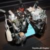
Ned Posted February 2, 2013 Share Posted February 2, 2013 Hi all, as some of you know, i have purchased another KP. Bought it last year and did little to nothing to it thanks to some mad hours at work. This year it's time to spend some money on the old girl to get her up to my standards! Some pics of my first trip away (thanks snoozin for the lending of the bike etc!) So i bought some bits; The plan is to fit the bike carbs, tidy up the engine bay, fix the rust, tidy up the interior. Deadline for these is about 70 days from now for OS Nationals 2013 1 Quote Link to comment Share on other sites More sharing options...
Ned Posted February 2, 2013 Author Share Posted February 2, 2013 More relevant on Club-K rather than here maybe? But, what i did today, was go and buy the alternator shown above... It's completely wrong, but internally regulated so i decided to attempt to fit it today.... Below is my attempt. NOTE: This is merely my attempt, and not THE way to do the same conversion, just the way i did it. Theres bound to be way better ways of doing it! Don't actually remember where i got it from. Pretty sure it was a T170 Corona? Sorry about that lads. So it has the wrong type of bottom mount compared to the K series one, has the wrong front pulley, and the top mounting place is also in the wrong place (at 2:00 o'clock instead of 10:00) but it looked good at pick a part and it was mounted at an easy to get to place in the original engine bay (at the top) Cut the pulley in 2 pieces so i could get a spanner on the big nut and a socket on the shaft to undo it. The K series pulley is flat at the bottom, but the alternator i got isn't, and needs a pulley where the center comes out further. The K series one also has a bit the goes on the shaft onto the pulley to hold it all in So put the pulley on the lathe to make the hole big enough for that center thing to fit through Welded it on with the centre bit pushed all the way through. Not showing you my welding there and also stuck it back on the lathe to make sure the mounting surface was nice and smooth/flat etc so it mounts on the alternator nicely, and put it onto the new alternator. So the bottom mount normally goes on the outside of the K series mount on the motor, but this one goes in between, and it's far too big attack with grinder, and ta-da! (take meat of the pulley side only to push the pulley as far forward as it can get) Though the problem is that the holes don't line up thanks to the bar on the mount (engine side mount) Done So, i mounted it and found out that the puley doesn't quite line up... So i cut another 6-7mm off the pulley side of the bottom mount, and spaced it out with some 20mm steel rod i had lying around and drilled a hole in it on the lathe. No photo's of that sorry... May get one tomorrow. But now the belt lines up! Top mount doesnt meet up though... So took it off, cut it into 2 pieces and welded some steel in between it to lengthen it. IT FITS! (just, may need to get a slightly smaller belt?) Little video (not sure if this will work for you lot or not) https://plus.google.com/u/0/photos/115065803788643467273/albums/5840281817540874769/5840281816785966930?authkey=CITcz4qW5-P6CQ So tomorrow it's time for wiring it up and seeing if it actually works! Quote Link to comment Share on other sites More sharing options...
Ned Posted February 3, 2013 Author Share Posted February 3, 2013 So, heres a pic of the spacer i put on to line up the belts. So the wiring..... SO EASY! I just used the same battery wire, and other than that, the 3 other connections come from the plug that now goes to your regulator, handy right? So go to Supercheap, and get yourself a 6 pin Molex connector (they call it a quick connect 6 way connecor or something, and the guy had NO idea what a molex connector was. Thought i said Solex first, and then Rolex before he understood Molex) just go to the electrical isle and have a look yourself Then just crimp the 3 wires from the original plug with the flat blade terminals. Now this is the wiring on the plug on the back of the radiator (the colours were wrong for me) And if you're not sure what side of the connector you should be looking at, the lamp wire is the small one. So we have sense, ignition and lamp, which on my car were as follows; -Lamp, yellow -Ignition, black/Yellow -Sense, white So just stick the wires into the connector housing and connect it all up like so So, before; After Now it's time to see if you f@%ked anything up haha connected up the battery Car running IT WORKS! though shortly after it started making a horrible noise and the minimalistic weld i did on the back of the pulley let go and was scraping on the alternator, so i pulled it off, ground it back flat and welded both front and back and made a little video https://plus.google.com/photos/115065803788643467273/albums/5840281817540874769/5840811804026962706?authkey=CITcz4qW5-P6CQ Hope that helps someone with their conversion So been told theres a barina that may work better, and i did see one at pick-a-part and i thought it looked pretty close, but that one was very dirty and old looking so opted for this one. This one is one of the Toyotas "Compact, high speed alternator with built-in IC regulator" This toymods post helped me, even though all the colours were wrong for me http://www.toymods.org.au/forums/faq/2705-quick-guide-internally-regulated-alternator-wiring.html 1 Quote Link to comment Share on other sites More sharing options...
Ned Posted February 4, 2013 Author Share Posted February 4, 2013 Coil on plug anyone? hahaha (it's so so so big!) Thats a 2ZZ one that i was going to try to shorten, but turns out the reason the head is so small is because the coil itself is in the shaft, so not going to be able to shorten it at all So gave up and did this so that when i find a suitable solution, i at least have something done... Before; After What i did was try and drill out the pin at the bottom to take everything out, but failed miserably So just cut in in 2 with everything in place. After that i made a plug for the top on the lathe, that was a nice press fit. Shortened the shaft on the lathe as well so that the gear sits just as far from the housing as the standard one (about 2mm?) and bobs your uncle. Had to make the plug about 4 times as it was never quite right but got there in the end. So the shaft just sits in there without being held in place? is that right? I'm guessing it cant go any further down when it's in the block right? If thats not the case, how did everyone else get that sorted? and if that is right, should i make the shaft a bit shorter to make sure it doesnt touch at the top, on the back of the plug? So even though i have no idea if it will work, at least something was done today Quote Link to comment Share on other sites More sharing options...
Ned Posted February 7, 2013 Author Share Posted February 7, 2013 Not sure what's wrong, but i think this is going the wrong direction? Quote Link to comment Share on other sites More sharing options...
Ned Posted February 10, 2013 Author Share Posted February 10, 2013 Figured it was time to do more things, given that Nats is all of 60 days away now! So there was a bit of cancer in the Starlet, Behind the rear bumper cut cut cut weld weld weld welder playing up so needs finishing/tidying Floor, you can hardly see it, but the only thing stopping my foot from going through the floor is the chassis rail can no longer see the road under my feet while driving Scuttle Panel/firewall areas lifty lift Hope this goes back to looking like it did before the grinder/hammer/drill came out!!!! Getting there Theres a few more bits, but have posted enough pics already i think! Still some work left, and panel beater will be back on Saturday to finish it up. Won't tell you who the friendly panel beater is, but he'll make himself known if he wants to put his name next to his work Quote Link to comment Share on other sites More sharing options...
Ned Posted February 17, 2013 Author Share Posted February 17, 2013 Starting to look like a car again! Quick re-cap; Floor (it was a lot worse than it looks!) Thats the main stuff that was done anyway. Also sprayed most the chassis rails (inside) and a few little patches. Time for paint and a wof this week hopefully! Quote Link to comment Share on other sites More sharing options...
Ned Posted March 9, 2013 Author Share Posted March 9, 2013 So this is how it this morning (well, yesterday technically) Needed some grinding/tidying and the painting done. So tape it up Wrap it up in a large condom and make it so the patches are accessible Prime it up and put on a bit more cavity wax where it needs it LOOK! IT'S RED!!!!! Colour match is pretty good! DONE And flipped the centers on the wheels on the f@%ked one for lols. Will probably do this to the spares and use them on the trailer. May even weld the two inners together to get a nice 9" wheel Bit wide for the KP though! Oh, and the car is back together again (as you can see in those last pics) though it isn't keen to run for some reason... got the battery on the charger, as it's a bit flat. Would kick into life with a roll/tow start, but wouldn't idle on its own. Quote Link to comment Share on other sites More sharing options...
Guest Ned Posted March 14, 2013 Share Posted March 14, 2013 So, quick little update, with the PROPER info on how to do in internally regulated alternator swap on a K series!!!! Firstly, i will show what happened to the last attempt i made... so chewed it up nice and proper! Next was to buy a 7K alternator for $125+gst (and a trade in alternator) from some toyota wrecker on the north shore. Compare this to the unit i had in it, and you wonder how/if it even makes power... but it can keep a townace/noah running, so a starlet shouldnt be a problem! IT"S SO CUTE AND TINY! and one of the numbers in case someone needs them; So mounted that, replaced a dead fuse and she worked well Also got the car up to temp and did a compression test which netted good results... 192, 190,200,185 or something like that anyway. Didn't write them down. Number 1 and 4 plugs were wet though, which was weird. Checked timing and was set to 10deg at 1000 RPM (with the vacuum advance connected, which i assume is the right way to do it?) Gotta get some new plugs and leads, but got cap, rotor, condenser and points today to replace them. Figured i might as well give the ignition a birthday (before pulling it off to replace with wasted spark) AND i got some new wheels today from Mr Fels. Will get some tires tomorrow and post up a pic of them then, but they look like these ones; They are Advan YHs, 14x6 and will fit some 165 60 14's tomorrow which should hopefully look the part Quote Link to comment Share on other sites More sharing options...
Guest Ned Posted March 17, 2013 Share Posted March 17, 2013 Doesn't deserve an update really, but.... WOF Wheels/tires 2 Quote Link to comment Share on other sites More sharing options...
Ned Posted May 15, 2013 Author Share Posted May 15, 2013 So time for an update on the bike carbs.... For starters, they still aren't on. I tried to get them on before Nats and even stayed back in Auckland a couple extra days to try get them running but was a no-go for now. Anyway, The bike carbs i got (GSX1100's apparently) are 34mm carbs, and the ports on my 7K are MUCH smaller so needed do do a reduction of some kind between carb and motor. I chose to do the reduction as far back to the head as possible, and used the 12mm plate for the manifold to do the taper. With the carb being 34mm, i decided that using a 1.5" pipe with 1.4mm wall thickness would be good, as that gives me an ID of ~35mm to go with the 34mm carbs. So i got slacker.cam to draw me up a manifold with the required taper; and then got sentra_dave to machine it out on his giant machine The manifold actually ended up being wrong, as both me and cam didnt spot the error so got it remade. The taper is wrong. The one on the left is what we drew up, without thinking too hard, and did it wrong because we needed it to be like the picture on the right, so sentra_dave made the required changes and we cut another one. The block sits on a 20deg angle, and the carbs sit on a further 10deg angle, hence the pipe coming off at 30deg angle from the flange. so this is the new flange; The carbs have a different spacing, so needed to make it all match up I used 180deg bends from AutoBend and the good thing is that because i made it to the pipe connects at a 30 deg angle, to match the motor and the carb, the runners could be straight and only had to bend to bend to change the carb spacing. Yes, i probably could have gone straight and used silicone joiners and probably get away with it, but i wanted to try match it up nice and snug. Here is the "final result" to give you an idea of what i did before i start explaining how i did it and a mid way shot So to make the runners match up, you need to obviously figure out the spacing on the motor ports and the carbs, so figure that out, and then figure out the difference between centre lines. These are make believe values, as i didnt document this part So next is measuring and cutting time of the 180deg bends. Now i feel like i should explain something first. This might be blindingly obvious to some, but might not be to others so i'm adding this anyway (as it's my thread and i can do as i want ) turning a 180deg bend into a straight pipe with an offset is as simple as cutting it in 1/2 and turning 1 end over. And if you want to narrow the offset, you just cut some out of the middle of the pipe. And the part i wanted to explain, was that it doesnt matter what angle you cut the pipe at, as long as both sides are the same, and it will match up perfectly. So, to change the offset, just chop a bit out the middle and the angle doesnt matter at all, as shown below; as long as the angles are the same! (exaggeration below) So i setup a drop saw with a 30deg angle (as i needed 30 deg for the ends to match up with the flange anyway) and then started measuring and cutting. First, i would rub the bend on my bench to lightly mark the highest part of the bend Here you can (somewhat) see the marks it made and then marked that up with a vivid Then i grabbed a bit of scrap 50x50 to use as a straight bit to put the straight part of the bend against to mark where to cut it. So going by that measurement drawing above, the spacing between 2 of the ports is 20mm, so the offset between the straight bits needs to be 20mm, which is 20/2=10mm a side. The pipe is 38.1mm so 38.1/2+10=29.05mm. So set your straight edge dude to 29.05+50mm (from the 50x50) = 79.05mm and put it against the far edge of the 50x50. Now where the end of the straight edge crosses with your earlier mark, is where you want to cut it, so mark that. You will need to cut your bend roughly in 1/2 to get it to fit in the drop saw, but after that, put it in the drop saw and cut off where the mark is. Again, any angle is fine as long as you dont change it. Then when you've both, debur them (i used a knife as it's only ally) and they will fit together like a glove and be perfectly straight repeat for all 4 runners Now line it all up so you know whats what and make sure you have all the runners. I numbered them, which was probably a good idea. After that i cut the ends at 30deg to match the flange and cleaned up the edges with a knife. Now chop the other end to length as well, nice and straight. And then you're ready to give them to the man to glue them together! Dont have any more pics sorry, but here are the carbs all mounted Just a random note. We put that bar in between the 2 sides of the manifold to hold everything together at the right spacing etc. It can get cut off now if i want, but i'm leaving it there for now. It's handy having a handle to take everything of in one go and it's not in the way of anything so there is no harm in keeping it. Carb tuning didnt go well, so i wont go into that until i sort it out Thanks for reading! not that i expect you really did read all of this haha 8 Quote Link to comment Share on other sites More sharing options...
Ned Posted June 7, 2013 Author Share Posted June 7, 2013 Been a while... Been collecting goodies! Have these coming; Rush Automotive Extractors for my 7K Rush Automotive Baffled/modified sump (sample pics of previous work) and a K-T bellhousing (fairly rare) so that i can start strengthening my drive train before i build up my supercharged injected 7K with the power of 2 4AGEs combined because RACECAR/van Also have a spare injected 7K sitting in the garage that i picked up for a very good price from pick a part suspect BHG though but will be rebuilt to handle a reasonable amount of power. My uneducated mind wants to aim for 200+ HP ATW with an SC14 but will need to talk to the engine builder man to see how obtainable that is on my budget etc. Might put motor building on the back burner for now and sort the rest of the car first and just enjoy the bike carbs for the next couple years instead while doing diff brakes body etc. Go see Rush Automotive for all your K series needs guys! Sheldon does exceptional work! Took a while to get the bits for me though as he's very busy 90% of the time but should be worth the wait 1 Quote Link to comment Share on other sites More sharing options...
Ned Posted October 31, 2013 Author Share Posted October 31, 2013 Gave the car a bit of a tickle up. Gave it a wash, clay bar, machine polish and then a wax. Came up WAY better! Best $100 i've ever spent on the car TBH, and thanks Alistair for the car detailing write up, came in handy Bonnet before, with icky marks and dull colour Bonnet after (late at night in the garage so actually looks better than the pics!) Roof before Roof After That plus doing some maintenance like new wheel bearings, brake pads, oil, wheel nuts etc is really all i've done... but it's WOFed and Reged for all of summer, so keen to get some cruising miles done this summer! I think theres a couple photos floating around from the weekend at Pauanui last weekend, so i'll try find them for day time/sun pics of the car. 2 Quote Link to comment Share on other sites More sharing options...
Ned Posted January 15, 2014 Author Share Posted January 15, 2014 So i never showed you guys what this looks like clean and in the sun! this was a little while later and wasnt quite as clean as it could/should be, but here she is! Then me and Dion bought a parts car together. Jap import with sprint seats, fender mirrors, electronic ignition, fuel injection etc My KP isnt even that slammed, but that there is a decent difference anyway, what i've been up to today... before after Looks quite bare ATM... fender mirrors tomorrow i hope 3 Quote Link to comment Share on other sites More sharing options...
Popular Post Ned Posted October 30, 2015 Author Popular Post Share Posted October 30, 2015 wow... been a while! Used the car as my daily for 6 months earlier in the year and went fine. Now it's time to actually EFI it though... before drag day (i hope). So i figured, the best way to do that is the hardest way, and thats by designing my own ECU... All i have to design is the hardware, i'll be using FreeEMS to actually run it all, but their current hardware leaves a lot to be desired in my eyes. so let me introduce MicroEMS! a play on words between MicroSquirt and FreeEMS because i made it use the same connector and pinout as the microsquirt, so that if FreeEMS software or my hardware all turns to custard, i can just buy a microsquirt and plug it in a 3D render from the board design program; So i have actually just ordered 10 boards, and am trying to get my digikey account un-frozen so i can order the components for it as well and start building it in a week and a bits time I've been wanting to design an ECU for a LONG time and never really pushed through, but over the last few weeks i've put a lot of hours into designing something and going to finally give it a go. I shall keep you all updated 21 Quote Link to comment Share on other sites More sharing options...
Popular Post Ned Posted November 8, 2015 Author Popular Post Share Posted November 8, 2015 Spent the weekend at Cams working on the car. did this on Saturday and prepped the new 7K to put back in (theres 2 7Ks in this image followed by some fireworks show Then sunday, put new engine in the hole Fuel tank out, ready for EFI conversion didnt actually take any photos of stuff really so not much more to show and then the end of the day, stacked some cars in Cams garage KP is the first and only car to have been on the hoist, and this was the first time cam parked his precious 86 under another car on his hoist. Hope it's still standing! and then today, i received a nice box of bits from DigiKey. 988 little tiny capacitors and resistors etc, so ready for the PCBs to turn up! 10 Quote Link to comment Share on other sites More sharing options...
Ned Posted November 11, 2015 Author Share Posted November 11, 2015 carbs are for suckers! also put a hole in the fuel rail for this So now i have a fuel pressure sensor on the fuel rail to go back to the ECU. Not needed, but i'm going to run a Bosch 044 (china 044) and thats gonna be a little overkill, so going to reduce the flow so want to be able to log the fuel pressure to make sure its not too much for the standard fuel pressure reg, and also enough for when i'm at max fuel etc. 7 Quote Link to comment Share on other sites More sharing options...
Ned Posted November 11, 2015 Author Share Posted November 11, 2015 just picked up some more fuel related bits from Tim at TTT Auto Engineering and Segedins. Cost a pretty penny more than expected, but is a lush job, and SHOULD be big enough to feed a 7K 2 Quote Link to comment Share on other sites More sharing options...
Ned Posted November 12, 2015 Author Share Posted November 12, 2015 just got this delivered! 9 Quote Link to comment Share on other sites More sharing options...
Popular Post Ned Posted November 13, 2015 Author Popular Post Share Posted November 13, 2015 so i put some parts on! thought i'd share some of the steps for those who find this interesting and are unfamiliar with the process... so first of, you need to design a PCB on the computer, send it away and then PCBs show at your door 2 weeks later like so; Now we have a few options. I could throw dollars around and get a contract manufacturer to put the parts on. They charge about 20c per component to place (as a rough rule of thumb) and then there is a one of charge of ~1500 to get them to setup the machines etc. Very handy when you;re making hundreds/thousands of the same thing, but not when you have to make 1 board to make sure it works first! Option 2, you get friendsly with your soldering iron and you place all the parts one by one and solder them on with the soldering iron. This is how many DIY people do it at home, but this isnt the fastest and doesnt have a very good end result normally as nothing is on straight, and the solder leaves heaps of flux behind etc. Option 3, the option i went with, is spending a little more money, and the man making the PCBs will also make you a stencil. Normally these are grown (yes, grown, it's weird!) but the cheap option is laser cutting them out of thin stainless. What a stencil is, is where there are pads that need solder, they make a hole in the stencil so you can squeegee some solder paste over the top and it leaves solder where you want it, and not where you dont. The other option is using a solder paste dispenser, which is a little syringe driven by air to put some paste where you want it. anywho, solder paste is just that, a paste made of little tiny balls of solder, mixed with some flux. The flux makes it all stick together, and also helps the heat transfer around all the little balls of solder, and when you heat it, it all turns into real solder so after you put some solder on (hard to tell in the photos) we are ready to place some parts! and here is the first part placed! (brown-ish, slightly up from the middle) about an hour later, and all the little passives (caps, resistors etc) are placed! left = done, right = to-do hour 40, and all the bits are on! Notice the tweezers used to place the parts that board is about 65x90mm to give you some size ideas. So before you all ask "why place such small parts on a DIY board?! that seems way too hard!" well, those parts are actually quite big. They are 0805 SMD parts, which means they are 0.08 x 0.05 of an inch in size (2mmx1.25mm) which seems small, but these days people will use 0201 on a regular basis, and even though most get a machine to place them, some still do manual rework on them. Most contract manufacturers dont even have a machne capable of placing 0201s by machine and get done by hand. So 0201 is 1/20th the size on an 0805 the two circled parts are both just a resistor and do the exact same job, just a different size Now that the parts are placed, we get to heat up the whole board at once to reflow the solder and turn the solder paste into real solder and hold the components on properly This is done with a hot plate. Big aluminium plate that gets heated up to 200deg C and then you put the PCB on and solder paste turns into solder right in front of your eyes Sorry about the shit camera work, but heres a video in case you feel like seeing how it works Now just need to put the through hole parts on, and fix the solder bridges etc, and power it up and see if it blows up... (i hate that part... like starting an engine for the first time after a rebuild haha) edit! do they look similar? best thing yet though! it lights up! and the computer enumerates the serial port 37 Quote Link to comment Share on other sites More sharing options...

Recommended Posts
Join the conversation
You can post now and register later. If you have an account, sign in now to post with your account.