


Adoom
-
Posts
2198 -
Joined
-
Last visited
Posts posted by Adoom
-
-
1 hour ago, cletus said:
have a look in the suspension standard on the lvvta website, the requirements for welding struts is in there
Ta. Found it.
-
I found a FB post from LVVTA in 2020.
Basically, if the strut tube is cut, then it needs NDT. If all you have done is remove the lower platform and fitted a threaded sleeve with a weld top and bottom to the std length strut tube, you only need to meet general welding requirements.... But your certifier can still request that you get an NDT.
-
On to the front struts.... There's no off the shelf option for a triumph. I suppose I could just get custom springs and cross my fingers the ride height will end up where I want it.
What's the deal with making your own coilovers these days? Other than "don't weld to anything cast". I assume Seedy Al's guide is out of date now.
Can you still weld a threaded tube to the steel strut body and just add platforms/nuts? Where do you source them?
Can you shorten the strut tube for shorter inserts(using the threaded tube to sleeve the join)
Does it need to be xrayed? Need to be done by a certified welder?
I had a look in the CCM and didn't find anything.
-
Redline performance will order only the rear BC Gold coilovers for me for $1195. So I'm gonna do that.
-
 1
1
-
-
I've got some worn out, really old TEIN coilovers in the S14 IRS that I've got in the Triumph. I asked Driven Performance if they can supply just the rear in the new style with the adjustable body. But they say TEIN will only supply full sets.
But they can do just the rears in either Border, or D2.
Does anyone have experience with either of those? What's the quality like?
-
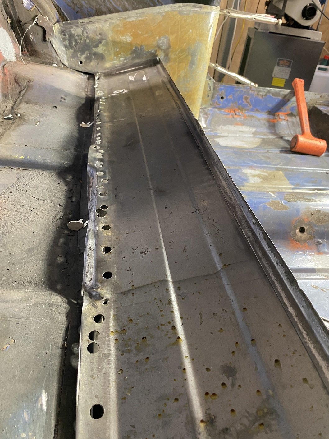
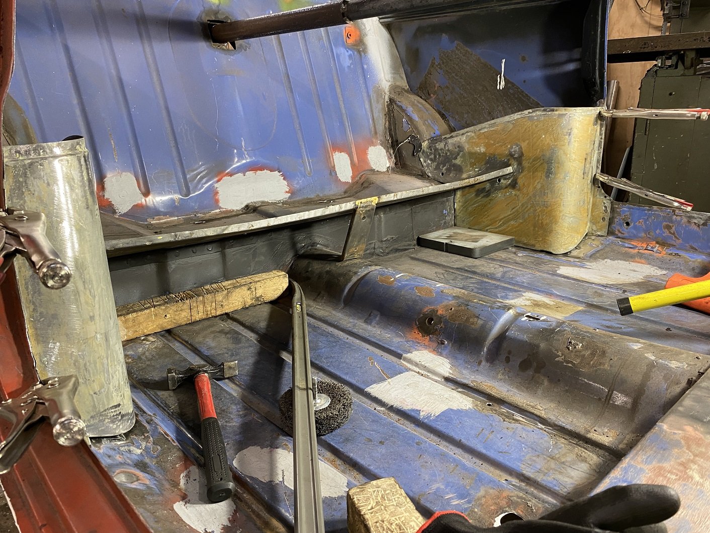
SO MANY HOLES to fill. The seat base originally is one big panel that includes the boot floor and it would join to a forward facing flange on that vertical panel. When the seat was deleted, the forward facing flange was cut off and the join was reinforced by wrapping a long strip of steel over it down the whole length.
But that leaves me with something like 30 spot weld holes with nothing under them.

So what's going to be less work, filling all those holes, or welding on a new flange(which isn't straight at all) so I can weld through those holes into the new flange?
It looks much more complete with the seat bits in there.
-
8
-
-
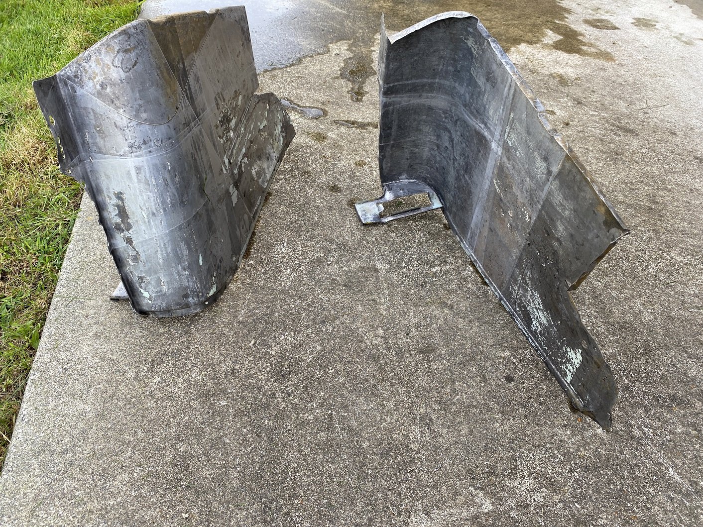
I've been stripping and derusting the donor rear seat pockets. I've also done the seat base panel, but it's basically just a flat panel.
I used paint stripper and KBS rust blast, same stuff as metal rescue but it's a powder that you mix with water. You can see from all the tide lines, my tub wasn't big enough.
They are just drying after I rinsed them with my outside hot tap.
There's a little bit of paint left to sand off and some panel beating to do.
These don't have the mount for the front seatbelt reel, so I'll have to make something.
-
7
-
-
8 minutes ago, bathcollector said:
It's going to be a stirling effort if you manage to get a 7/16 nut on a 12mm stud. I think you will be okay. have a look on Nice products site, they might have something that will work if you want to match the stud thread.
The S300 stud is the only one that looks like it might work. I'd need to measure for the shank length, might be too long. It's also 12X1.5 so I'd have to change the rear to match. I'd prefer to buy just one to test if the taper is correct. It seems no one in NZ who sells NICE has the S300. I'd need to get it from Aus I guess, but it says I must contact them for a shipping price.
-
1
-
-
So the Triumph has 12X1.25 wheel studs from the nissan IRS. And 7/16th UNF on the factory front suspension.
To avoid cross threading when the nuts inevitably get mixed up, I want to change the front studs to metric.
But the triumph has a tapered countersink for the head of the stud. All the aftermarket studs I've come across so far have no countersink with a flat head.
What are my options? Can I turn a taper on a flat head stud?(I'm guessing not). Or can I just use a flat head stud as long as the knurled section is long enough to fully engage?
Also, if I need to drill out the holes in the hub for a larger knurl, they are just straight holes right, the knurls on the stud "cut" the spline?
-
- Popular Post
- Popular Post
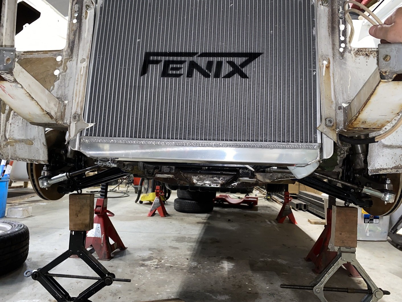
Tried a 5mm spacer under the rack. I think I'll leave it there, the rack tube is about 5-6mm away from the sump now.
-
13
-
- Popular Post
- Popular Post
I emailed LVVTA with my bump steer results and Greg the Technical Advisor replied that it looks good with or without the spacer under the rack.
Milestone passed!
-
13
-
2 minutes ago, Tiger Tamer said:
8mm is what the certifier told me I had to achieve when I Changed the Sunbeam tigers steering rack to a mx5 power steering rack. If I had the Toe change measured before I had pulled it apart then I would have only needed to make an improvement. I made my own bump steer bars from looking at their photos and using the measurement they gave to work out approx how long they were. I measured I had 3mm of toe change through the entire amount of suspension travel using them and that was the same as they measured on the wheel alignment machine.
Damn, that's a good outcome for yours. I'm going to try space the rack up further to see if it makes much difference.
-
1 hour ago, Tiger Tamer said:
I think 8mm is the maximum change in Toe you can have if you haven't had your bump steer measured before your modification. So you are on the edge there.
Is that 8mm based on their hypothetical 575mm diameter wheel? They use that size because it makes the conversion from mm to degrees super easy. Eg 10mm is 1 degree.
According to the LVVTA infosheets there's no fixed maximum amount of toe change that is acceptable. It depends on the vehicle. It's supposed to be "the same or better than factory".
16 minutes ago, cletus said:lvvta say 10mm is generally the limit for newer vehicles or custom independent suspension
20mm for older cars
id think 8 mm is likely fine, and probably better than original.
where the toe change occurs in the suspension travel is also important
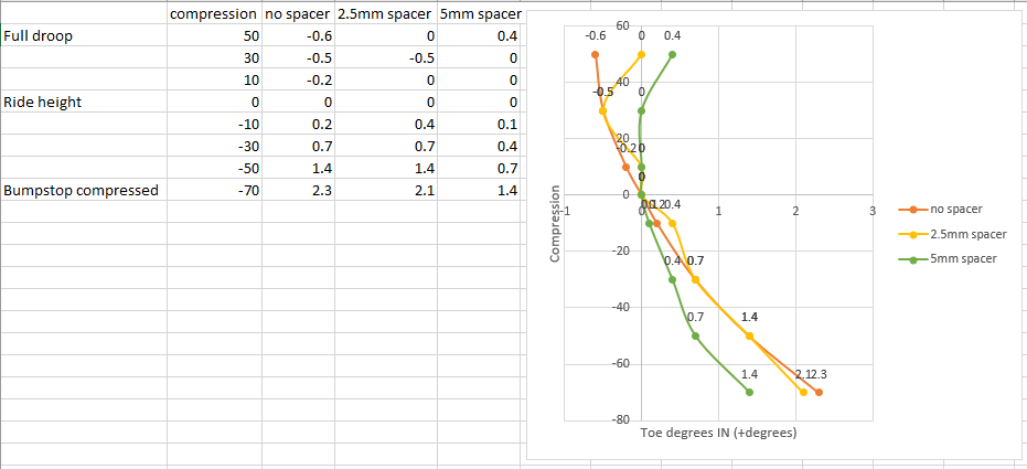
I think that 8mm was a measuring error due to the awkward way I'd previously been measuring it.
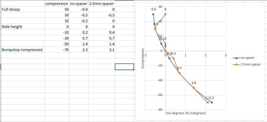
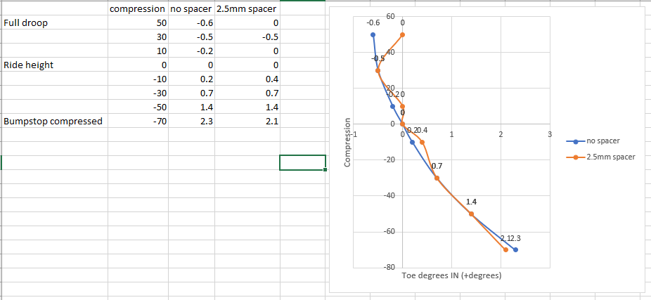
This is what I've got so far. Spacing the rack up by 2.5mm seems to have made little difference. I could possibly go another 4mm before I have clearance issues.
-
- Popular Post
- Popular Post
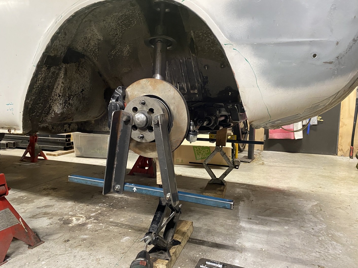
Using stuff I already had, I made some bump steer testing arm things. They are based on the LVVTA ones, but due to a lack of material, I made mine shorter, so you have to measure in front and behind the wheel rather than way out in front of the car.
I have 2mm holes drilled 575mm apart on the blue rods, this gives 1 degree per 10mm of toe. You measure the distance in front and behind the wheel and the difference between those numbers is the toe. The blue bars must be horizontal, you can see my spirit level on the other side.
You start off at ride height, adjust the toe until the front and rear measurements are the same, so you have zero toe. This is the stage I am up to now.
Then you move the suspension through its full travel(both sides evenly) and every 20mm, you record the distances for the toe measurement.
With my prototype welded arm and single sided bump steer gauge(which was quite hard to use) I got no worse than 8mm/0.8 degrees right at the end of travel.
Unfortunately, I don't know what the factory bump was, but I suspect it was quite bad.
-
13
-
- Popular Post
- Popular Post
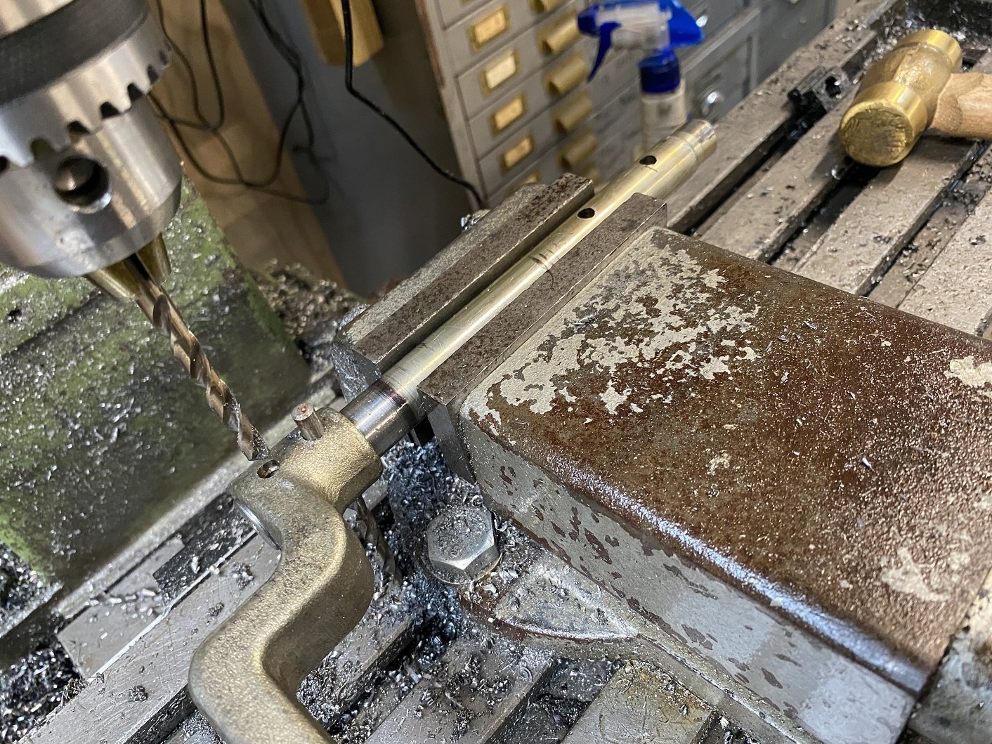
I finally got around to drilling the roll pin holes in the extended clutch pivot shaft thing.
I used the existing holes to align it by adjusting it until I could lower the 6mm drill bit through the hole without it catching the edge.
Here I have drilled the first hole and I'm using another drill bit to hold the arm so the next hole is in the right place.
It all worked out fine.
-
13
-
- Popular Post
- Popular Post
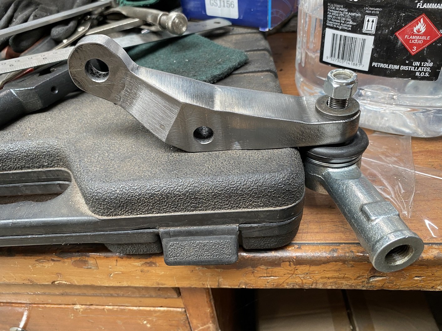
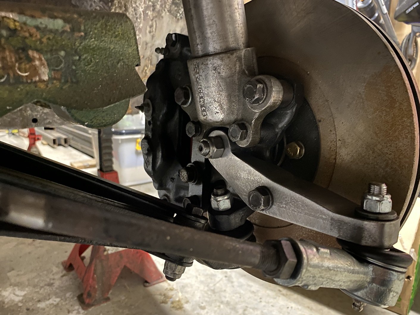
And the right side one is finished!
It also fits!
Both installed. This would be where full droop needs to be, any lower and the inner tie rod ball joint binds. There's another 60mm of travel to get to ride height.
I guess I need to sort out doing a bump test now.
-
11
-
- Popular Post
- Popular Post
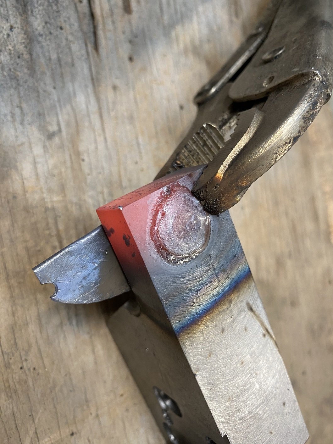
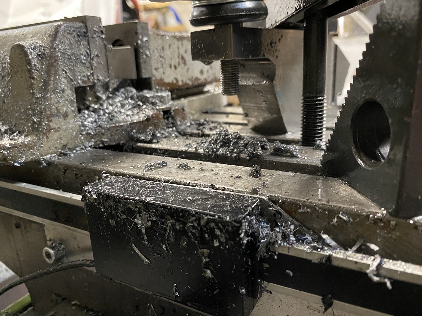
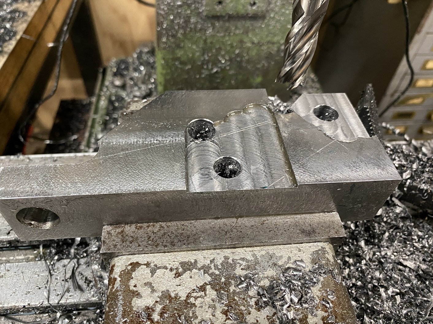
Turned the mig up to 11!..... or like 5, cause that's how far it goes. And installed the 0.9mm wire. Used a chunk I'd cut off to practice on.
So, lets do this.
I was concerned that the 20mm stick out would cause me issues getting penetration, but it was okay.
Did some swirlys until the hole was full. Then flipped it over, ground it back a bit to clean it up and welded the other side too.
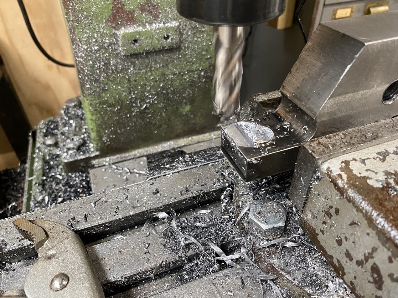
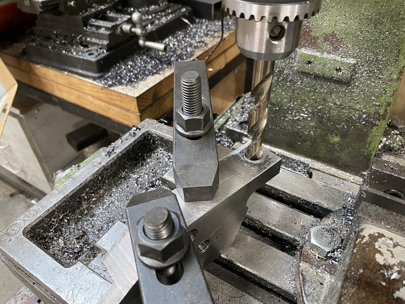
Mill that weld off. This side is the important one because it's where the nut goes.
Drill the hole again. Starting with a spot drill and working my way up from 5mm to 13mm. No issues with the weld being hard.
Use the 13mm drill bit for "precision" alignment when clamping it down for reaming. The table is locked in position.
And reamed it down just as far as the other one. I do have to use a washer with the nut, it seems that depending on which tie rods you get, the thread stops in a different place.
This little black divot is the only imperfection in the hole from the welding.
-
17
-
So the left side one is done. And it fits, thank fuck.
The ball joint is not quite binding, there's a little left. The inner tie rod joint is binding, but this is at full droop and I intend to reduce the droop travel when I get around to making coil overs.
I'll have to get on to trying to weld up the taper I messed up on the right side and try drill and ream it again. THEN I can see if I got the height right to fix the bump steer. If it needs fine tuning, I hope it can be sorted by spacing the rack up because I've got a little room there.
-
9
-
-
- Popular Post
- Popular Post
I procrastinated until 15:30pm before going out to the shed.
Milled the mounting faces on the left side arm.
I drilled a couple extra holes in the corners to make it easier to cut the profile on the bandsaw.
But now it's time to make dinner.
I'll probably do more procrastinating tomorrow.
-
11
-
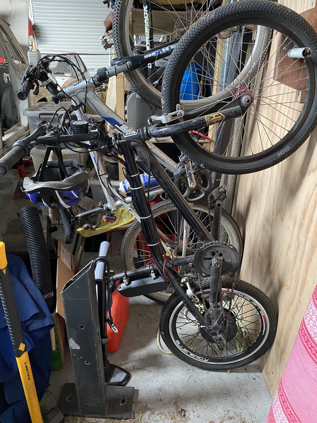
This is my, probably a terrible idea gonna hurt myself, e-bmx. 500W, it's got a mountain bike width rear cassette, but I bent the rear forks out and used a single speed conversion.
It's been sitting for ages, I kinda lost motivation when it came to buying cells and making a battery. I don't really want to spend the money for an off the shelf battery.
But I did get a spot welder that apparently is an okay one. It supposed to work best powered by a car battery, but I've not actually tested it yet. And a BMS. And some nickel strip.
But, dad has just offered me his old battery that is supposed to just have some bad cells. Hopefully it's actually the voltage I need, and I can find appropriate cells to swap in.
-
5
-
-
- Popular Post
- Popular Post
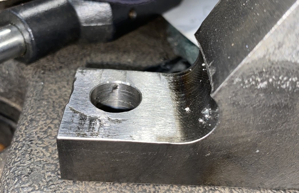
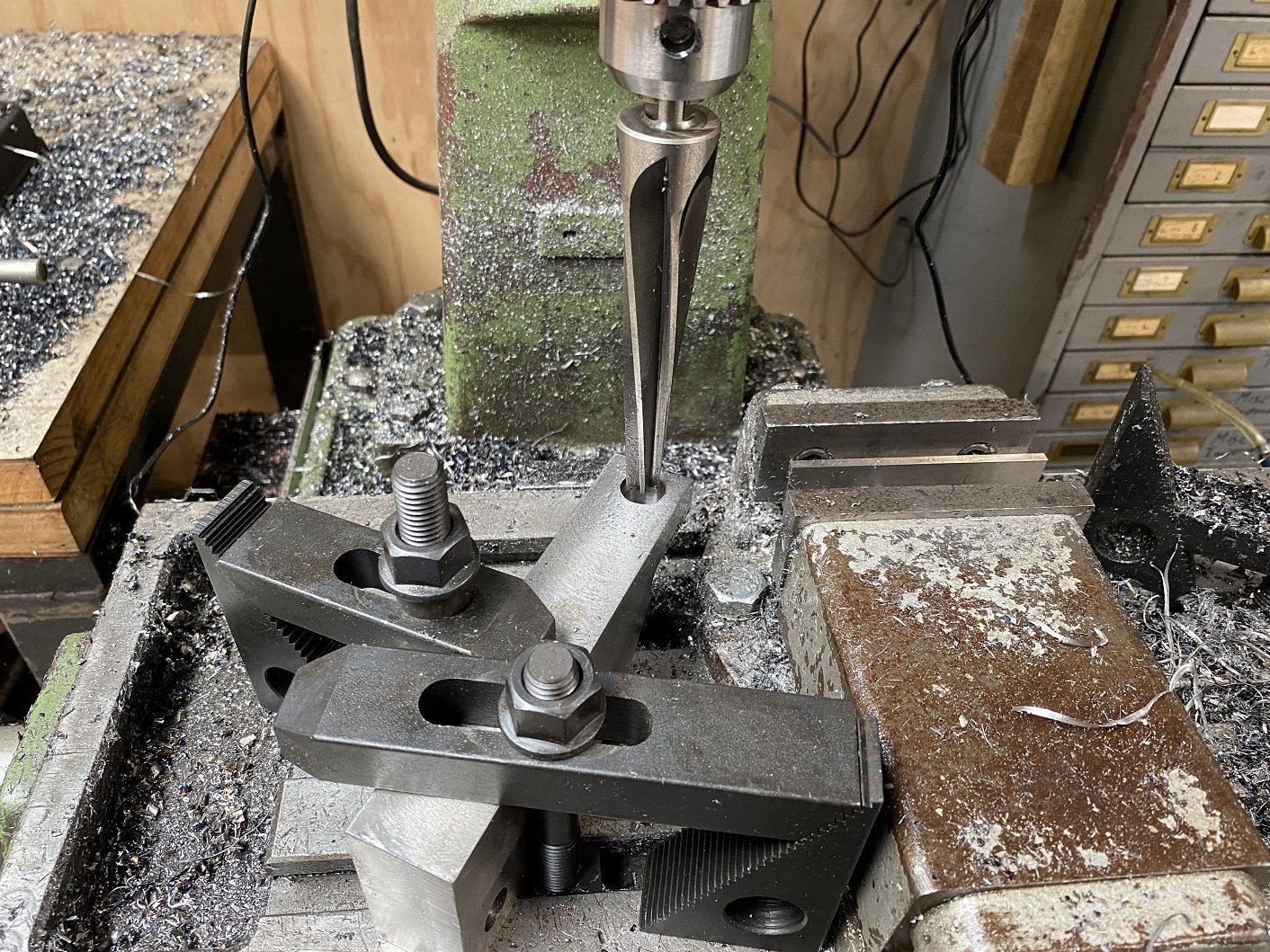
This is the one for the left side. I'll try weld up and redrill the hole in the right side one to try do the taper again, before I go making a replacement.
I used the drill bit in the chuck to line it up on the table and clamped it down. The reamer just sneaks in.
I put the mill on the slowest speed, 100rpm, used a bunch of lube and gently penetrated the hole. No problems with the taper this time.
-
16
-
9 hours ago, rusty360 said:
Please tell Me if I'm telling you to suck eggs here.
Also remember a reamer will just follow the hole before it. If the drilled hole was a bit Oct or triangle shaped the reamer will try and do the same thing especially in a drill chuck. Have you got a boring bar for the mill?
I learn all my machining from youtube and trial and error, advice and suggestions are welcome.
Ah, okay, I initially just wanted to start the reamer in the drill press so it was straight and continue by hand with the big tap wrench so didn't clamp it down, just held it still, but I got overzealous with the definition of "start" and it grabbed and got a gouge in the side of the hole. I assumed the reamer would be able to clean that up, but I guess it just followed the gouge.
I don't have a boring bar or boring head for the mill. But a boring head is on my wish list.
-
10 hours ago, rusty360 said:
What's the taper angle? Have you got a mill? I'd say the prob is the reamer flexing in the chuck, needs to rigid as possible, you really wana ream down to a stop to because I'd say it's trying to pull the reamer in?
When I say ream down to a stop I'm meaning ethier wind the knee of the mill up or use the stop on the quill and slowly work your way down. Don't try and hit it in one go. Depending on the taper angle you could step drill it to, just so the reamer doesn't have to remove so much meat.
It's a 7 degree taper.
https://www.amazon.com/gp/product/B07NMG3XWL/ref=ppx_od_dt_b_asin_title_s00?ie=UTF8&psc=1
Yes, I have a RF30 clone, a round column mill, so no knee, the Z axis is the quill, the whole head can be raised and lowered on the column, but it will also swing side to side so you lose any point of reference to the part.
I have the head low enough that I can just reach the bottom of the part with the endmill. But the taper needs to be cut from the top of the part, and the reamer is 165mm long and has a shank with 3 flats on it to go in a chuck, not a collet, so that makes it even longer and it doesn't fit without moving the head. So I used the drill press to avoid moving the head.
I guess I could just clamp the part directly to the table and that should hopefully give me enough room... And run the mill really slow. And use the fine feed, not the quill handle thing.
It didn't feel like the reamer is being pulled in, the flutes are basically straight, not a spiral.
It definitely flexes in the drill press.
-
1 hour ago, rusty360 said:
How are you doing the taper? Tapered reamer or machining it.
I have a reamer, it's huge, had to get it from the US, cost me over $200.
 It is the correct taper because it machined a perfect fit taper in aluminium.
I did it in the drill press, so it could have been too fast, or not enough pressure... or too much pressure. I think if I figure out the problem and try clean up the existing hole, the balljoint will go in too deep.
Early on I did try machine the taper, but it was such an awkward shape to fit in the lathe and I could not get the taper angle perfect, so I bought the reamer(the CCM says it has to be reamed anyway).
I think I'll have to try machine some test tapers in steel until I can make a good one before I scrap another thing I spent hours machining first. I probably need to go REALLY slow.
-
1
-


Tru Test wanted
in General Bike Chat
Posted
How much would you want to spend on one?