


Adoom
-
Posts
2,279 -
Joined
-
Last visited
Posts posted by Adoom
-
-
13 minutes ago, ~Slideways~ said:
I've been thinking about the lack of reverse, and the fact that I'll have fwd hubs doing nothing.
Maybe I could have a reverse motor connected to part of a fwd driveshaft. There may not be enough room to do it since it'd need to have a cv and a solid mounted starter motor and gear.
Maybe though.
Do you even need reverse? Since it's basically a mini and mini weight. Several times I reverse crash started mine by pushing it backwards just with the power of one leg out the door....
-
Wow! Slow down you maniac! You put the rest of us to shame.
-
 1
1
-
-
1 hour ago, Raizer said:
BOC D plan, think this year's bill was $145.
No monthly rental, no deposit, first year you get a free swap so that's 2 bottles.
I'm using D plan too. I just added an Argon bottle because I bought a TIG. Looks like the bill for the argon was $139. My Argoshield is $161 per year. That covers one free refill per year per bottle.
-
 2
2
-
-
My replacement subframe bushes arrived last week. I thought I should at least replace the wobbly front ones before I weld in any mounts for it.
What a bitch of a job.
The bush is bonded into a metal sleeve and that is pressed into the subframe.
I drilled a bunch of holes through the rubber until I could get the center of the bush out, then I used the reciprocating saw to cut into the metal sleeve. After putting a couple of slits in it, removing the remains of the bush was easy. Despite being careful, the imprecise nature of the reciprocating saw meant I cut a bit deep in one place and made a groove in the subframe. But I was able to fix it up with the tig.
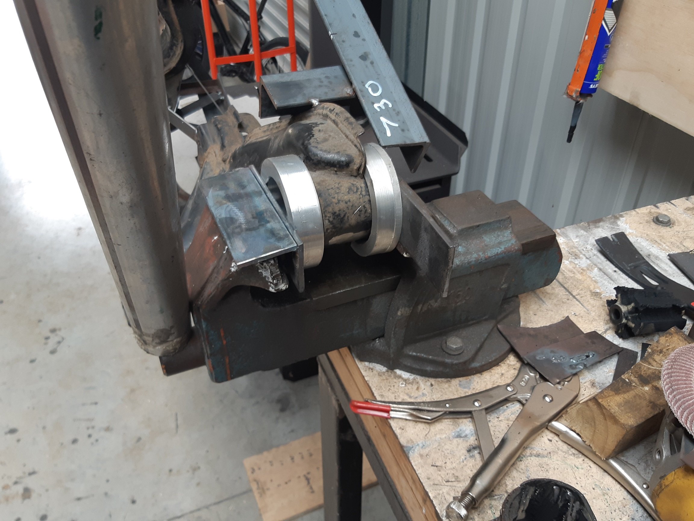
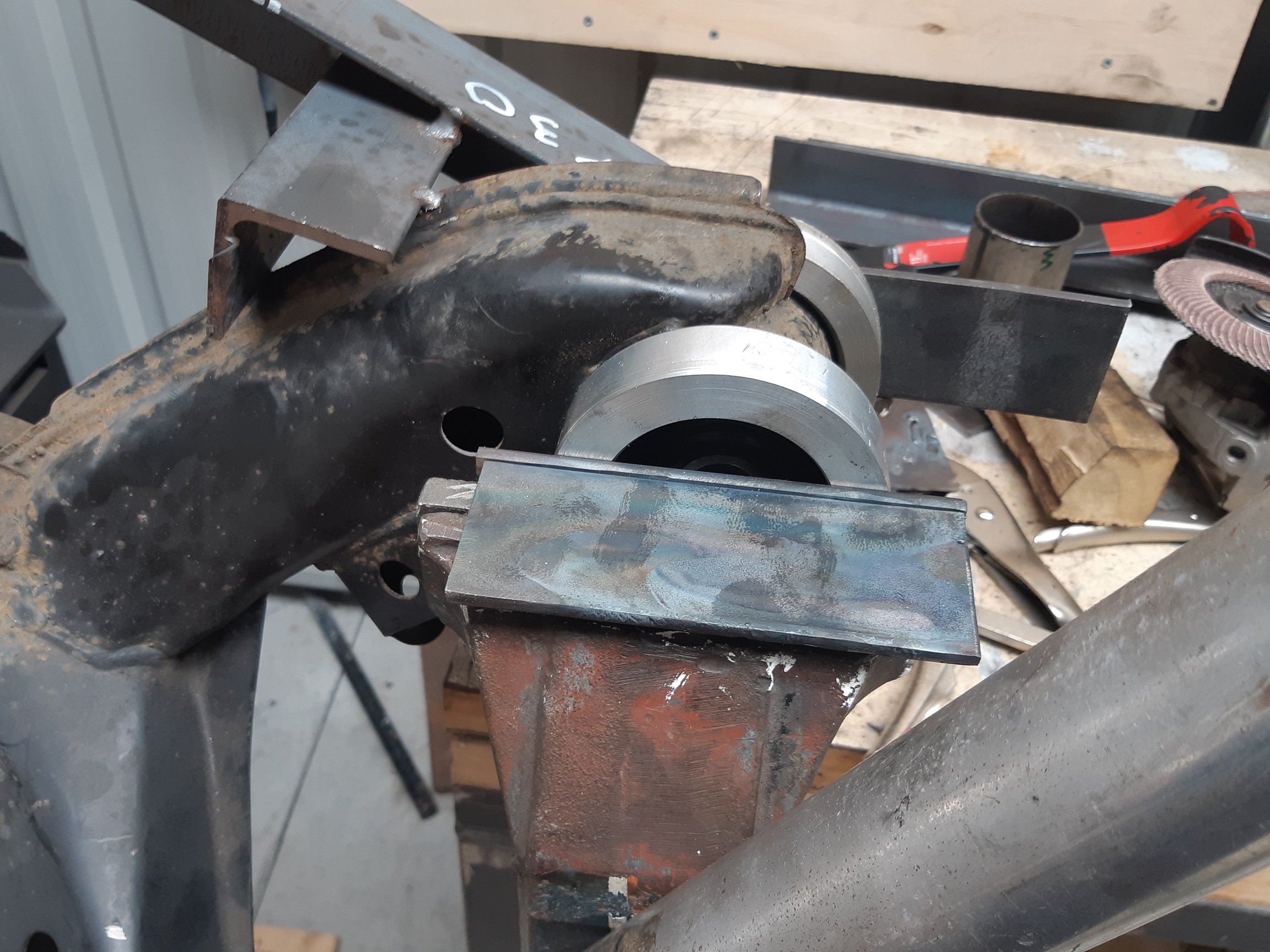
Then I had to press the new bushes in.
Hammer? Nope.
G-clamp? Nope.
Bit of exhaust pipe kinda the right diameter and using the vice? Sort of.
I ended up having to make two alloy rings. One to fit around the top of the bush and press on a metal lip. The other as a spacer because the bottom of the bush protrudes about 10mm.
And the vice, with a cheater bar. My poor vice.
Oh, and to make the rings... I used a holesaw in the lathe, which took a million years because I had to back out to clear the teeth every 0.0000000001mm depth of cut.
Then I asked the internet and found out about trepanning tools. So for the second ring, I made one of them out of the only HSS I had... 6mm square. It worked, but it was so thin it vibrated like motherfucker and cut millions of tiny needles.

-
5
-
-
25 minutes ago, weetbixkid said:
He says 1min 21 seconds around Mansfield. Is that fast/slow/average?
Manfeild? 1:21 is pretty fast.
Best I've done, in the 170KW starlet running semi slicks and giving it death was 1:24. I'm sure there are others on here who have done better.
AFAIK, a "fast" road car should easily do low 1:30.
-
2
-
 1
1
-
-
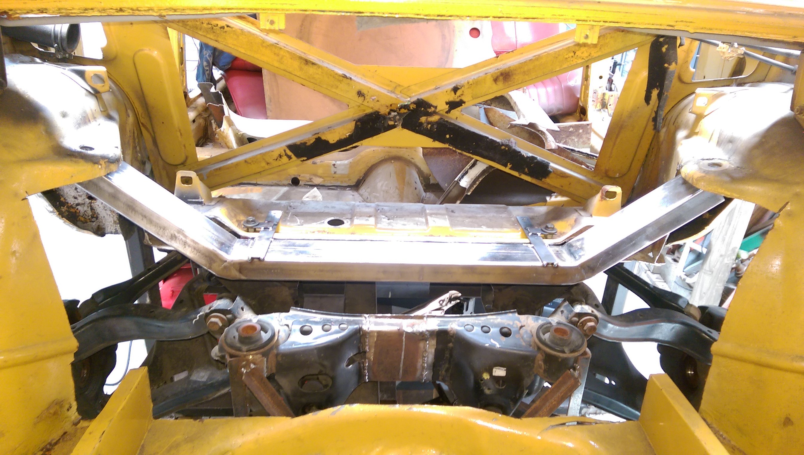
I made some additional temporary 'jig' brackets that connect into the original shock top mounts. I made them removable so I can still get the cross member out.
-
8
-
-
1 hour ago, ~Slideways~ said:
It would be pretty hard to get it to do as low as 4000rpm without running big diameter tyres, its more of a not going crazy doing a million revs while doing 100kph than matching what the bike engine donor would have done.
I've started cutting out rust on this thing now and have bought some spot weld drill bits.
The tiny holesaw kind?
Carbide bit in a die grinder is great for spot welds. Especially if you are only keeping one of the panels since it is easy to chew a big hole.
-
I have suspicions that this might be the same "M3" I saw many months ago, sometime last year, being driven through Lower Hutt, by a skinny guy with possibly a shaved head.
It only got my attention because the car looked tidy but the number plates were super fucked, turns out they were for a Primera.
/LING
-
1
-
1
-
-
Brackets
And welded. Not completely, I'll take it off and weld underneath. Standing on a stool(because the car is quite high up) leaning into the boot is not really the most comfortable welding position.
-
8
-
-
For the diff thing. My 900 hornet does about 4000 at 100kph in 6th.
-
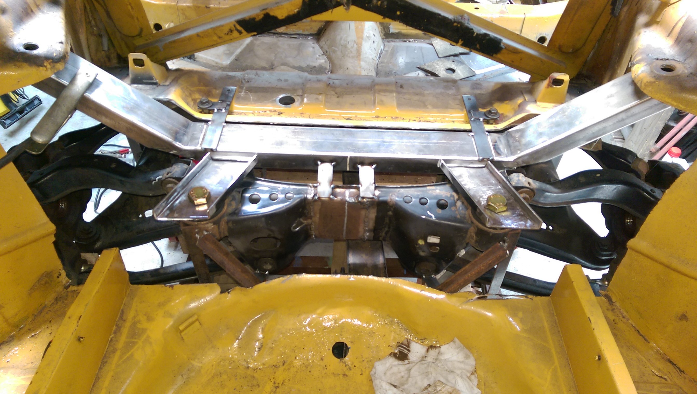
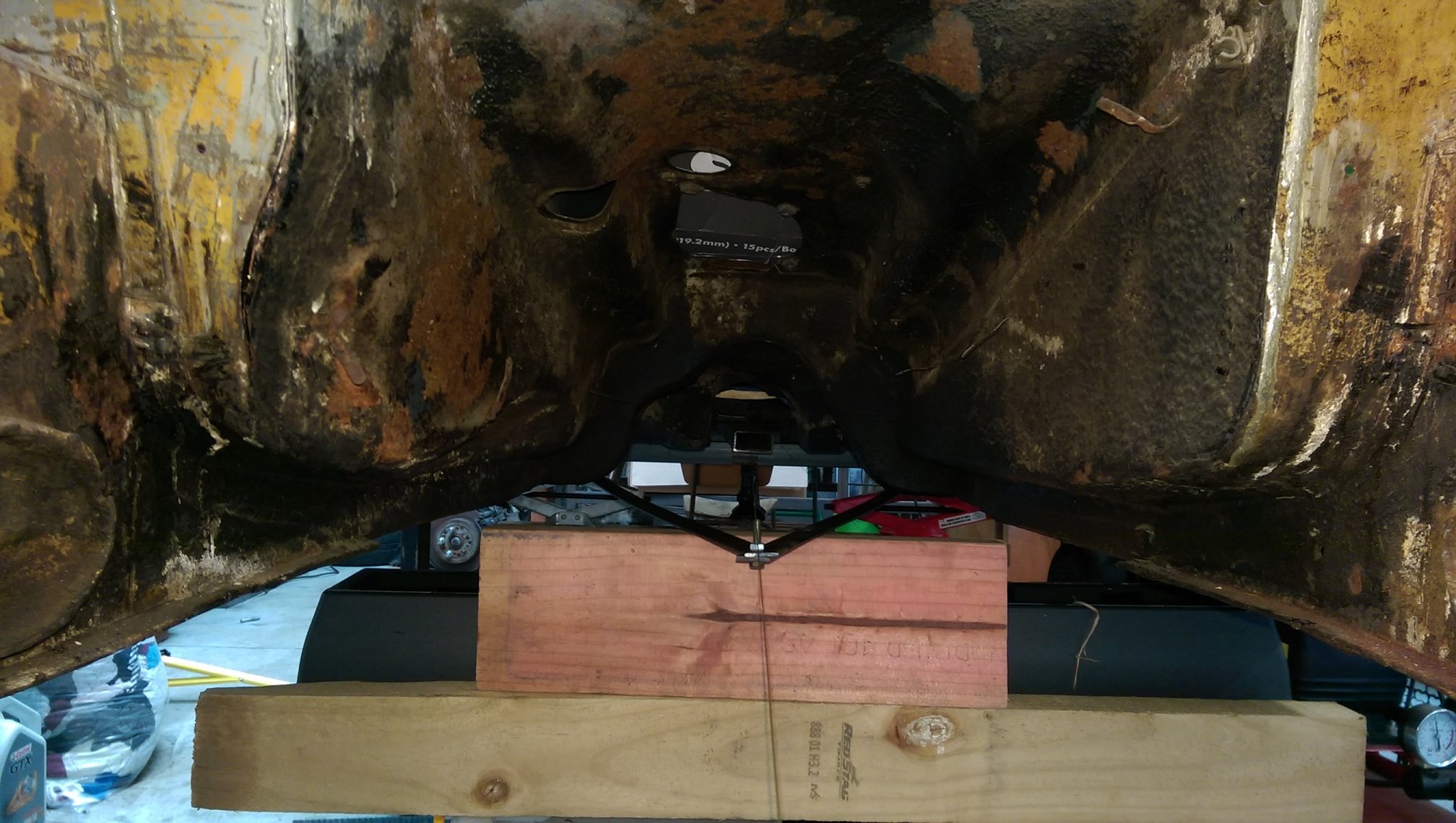
Using the body measurements in my factory service manual I found the centerline and ran a string down it.
I made a much longer isosceles triangle from the front mounts and lined the subframe up with the center line.
And raised the subframe up so the front mounts are not the lowest hanging thing under the car. The bolts are only there to hold the triangle, but I cut some holes to raise it up enough.
They are higher now than the original triumph mounts. Yes.... I used some worn out cut off discs as washers.
Then adjusted the height and measured it and measured it and measured it and measured it and measured it. Then temporarily welded it to my cross member so it doesn't move while I make the actual mounts.
-
8
-
-
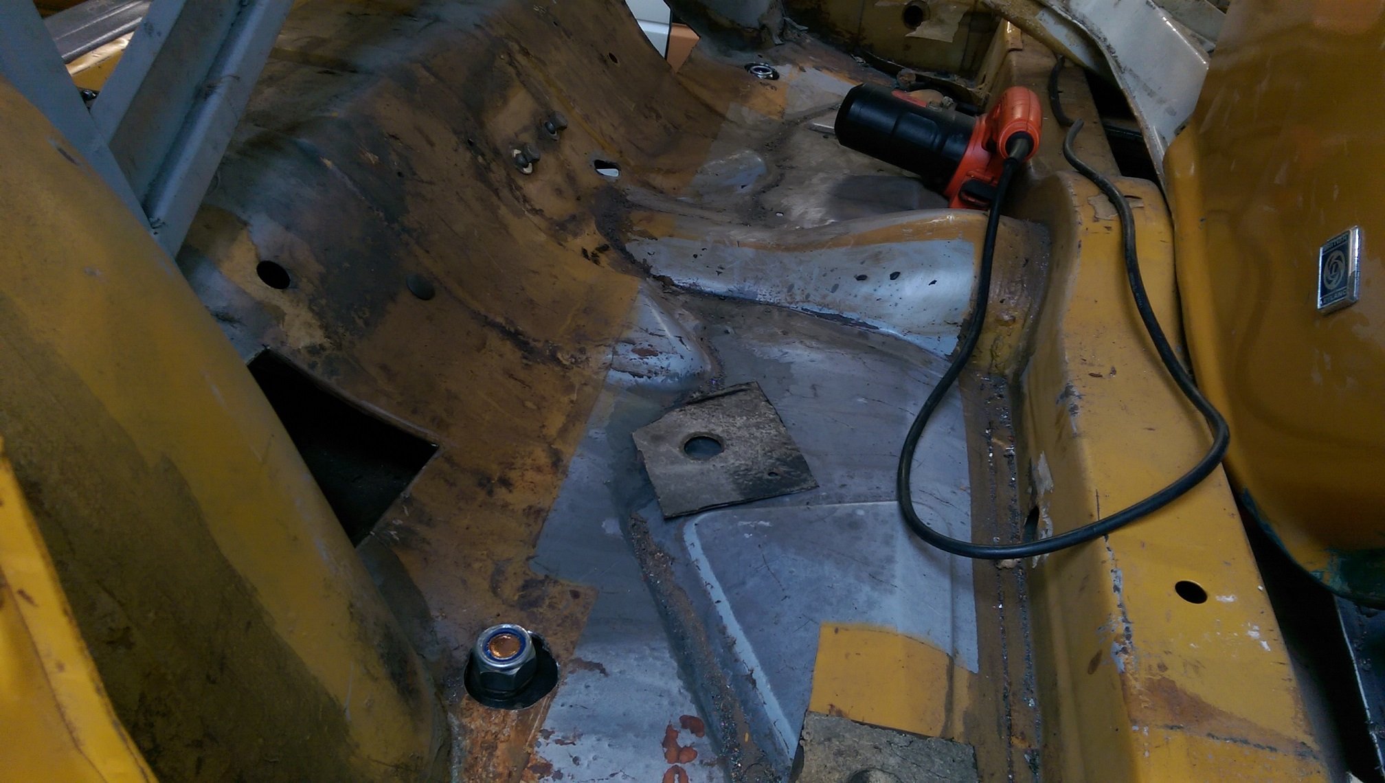
I made an Isosceles triangle. For making sure the subframe is central and straight. I'll make another much longer one from the two front mounts. Unfortunately those two mounts are torn, they are almost falling out, and I need to replace them first.
-
5
-
-
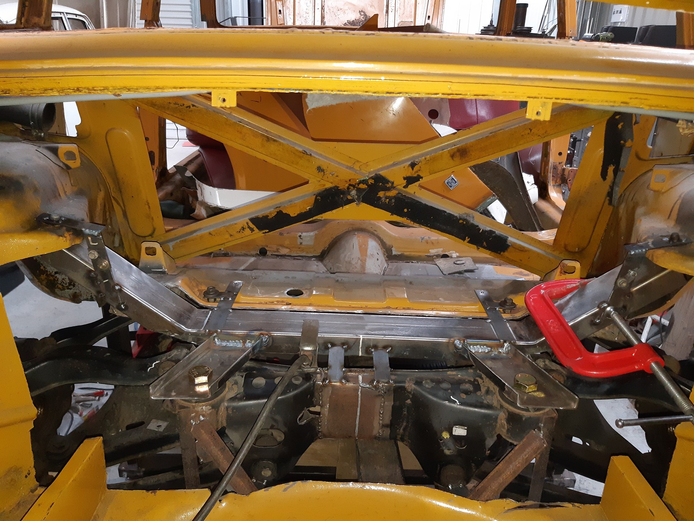
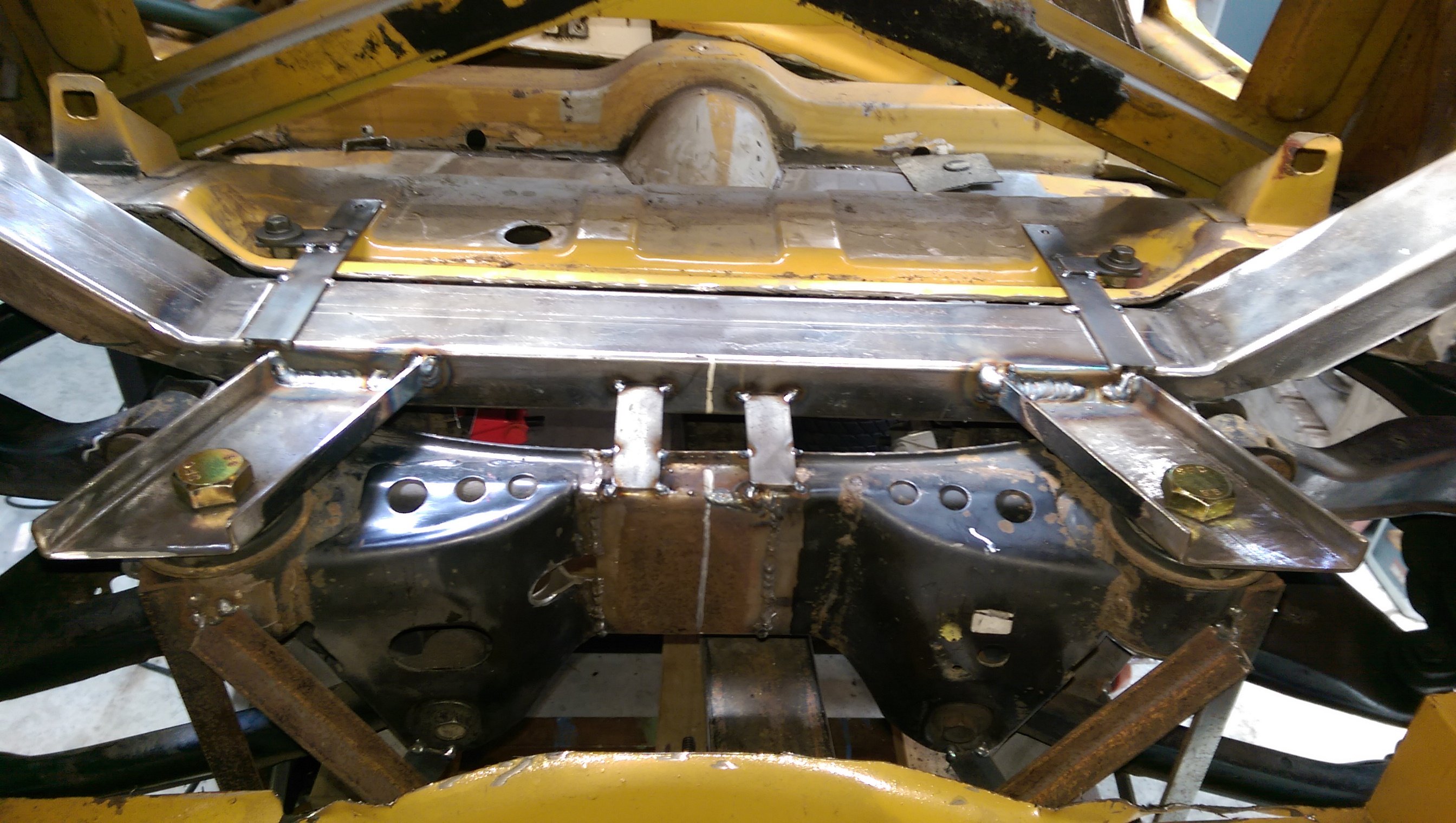
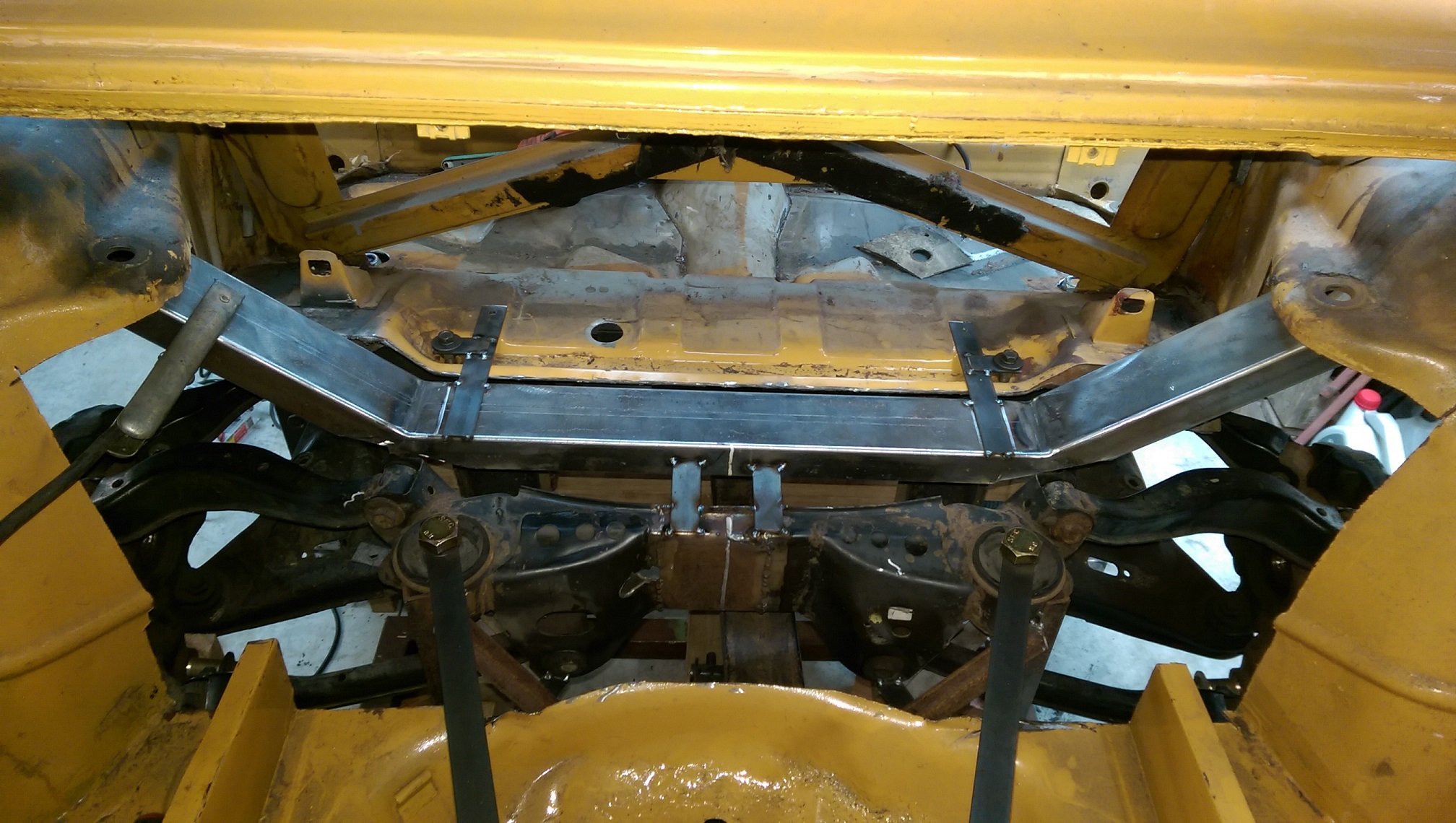
The existing rear cross member needed lots of modifications so I could get the subframe high enough and have room for the top suspension arm.
I realised it was going to be WAY less work if I cut the whole thing out and make a new one out of box section.
Snip snip.
Those straps tacked to the top are my alignment jig, the bolts use existing/factory holes in the body. I don't want to permanently mount this since I will transfer it over to the white car once I've worked out how it will fit.
The box is 3mm thick, so should be stronger than the original. I will tie it into the existing chassis rails which start just forward of it. The strut tops will be built off the ends of those angled bits, which I have intentionally made too long so I can trim them to fit. The angled bits follow the sides of the fuel tank, so it will/should still fit.
-
4
-
-
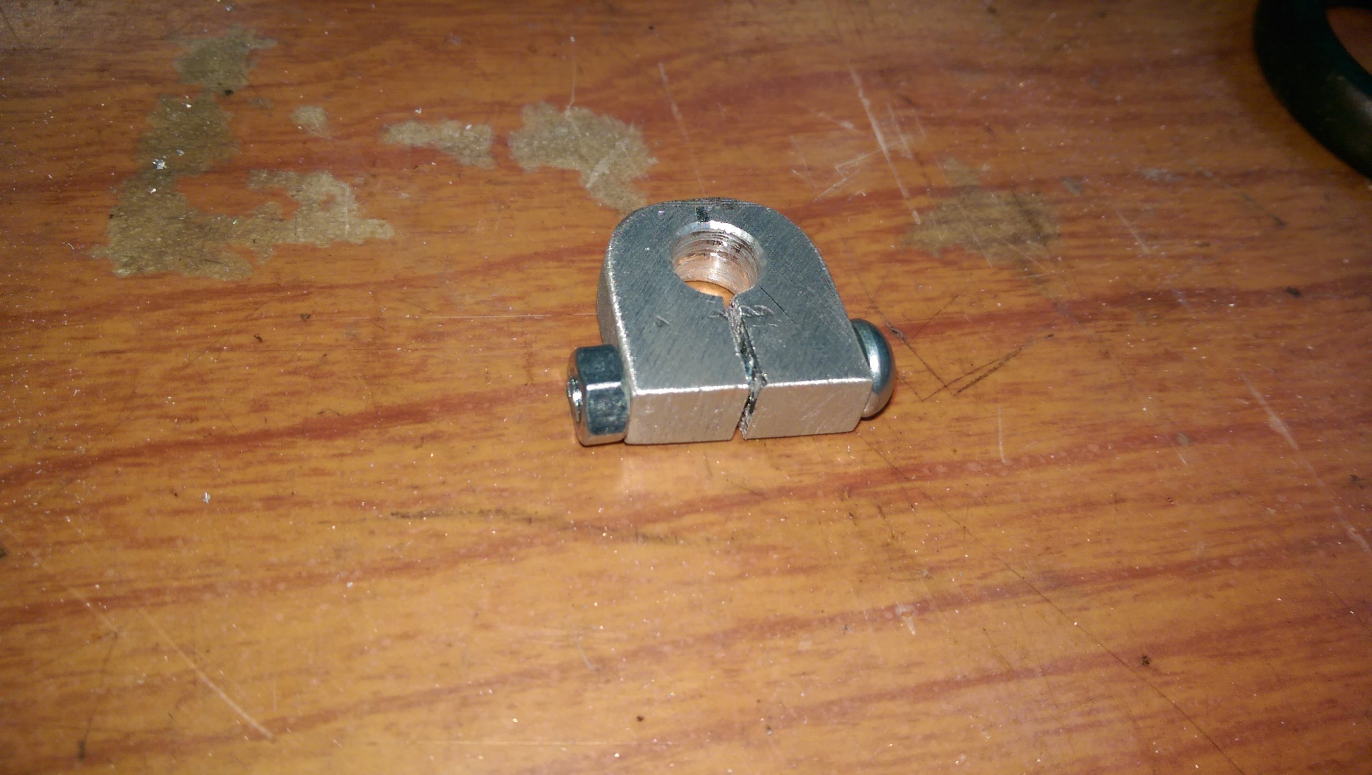
I made some round things with holes in them. I'm going to need to run 5mm wheel spacers(this is with 3mm washers).
-
2
-
-
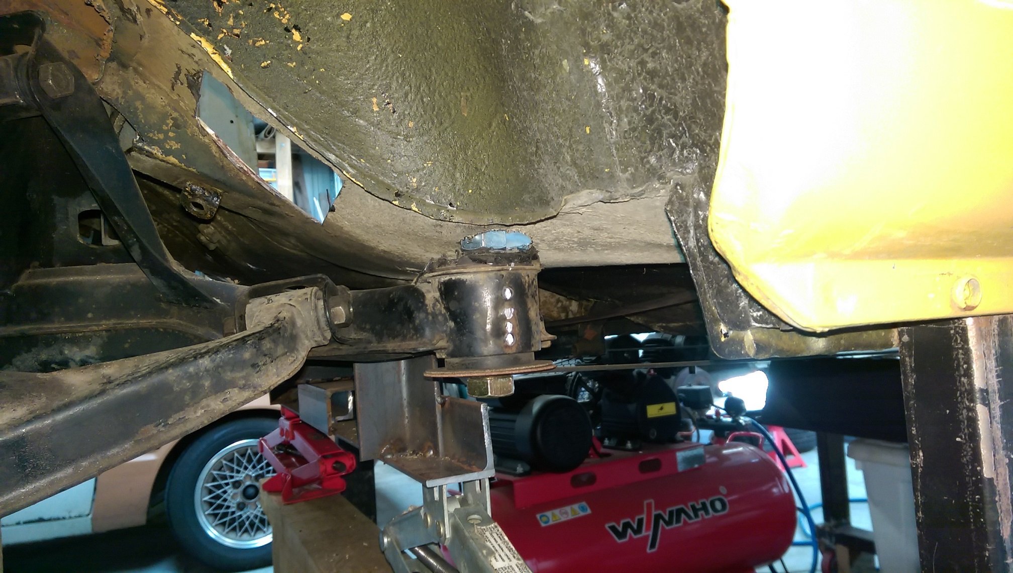
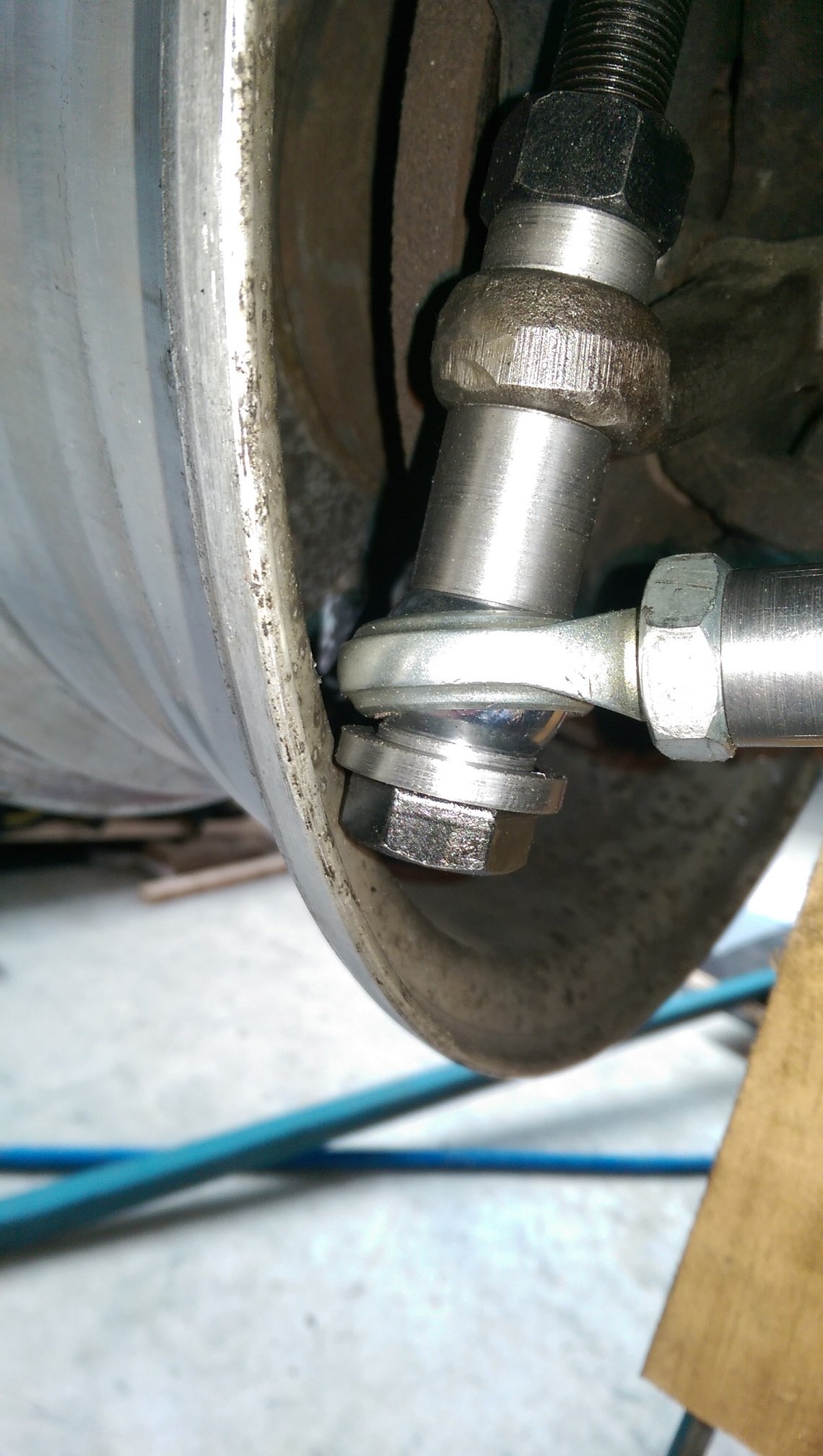
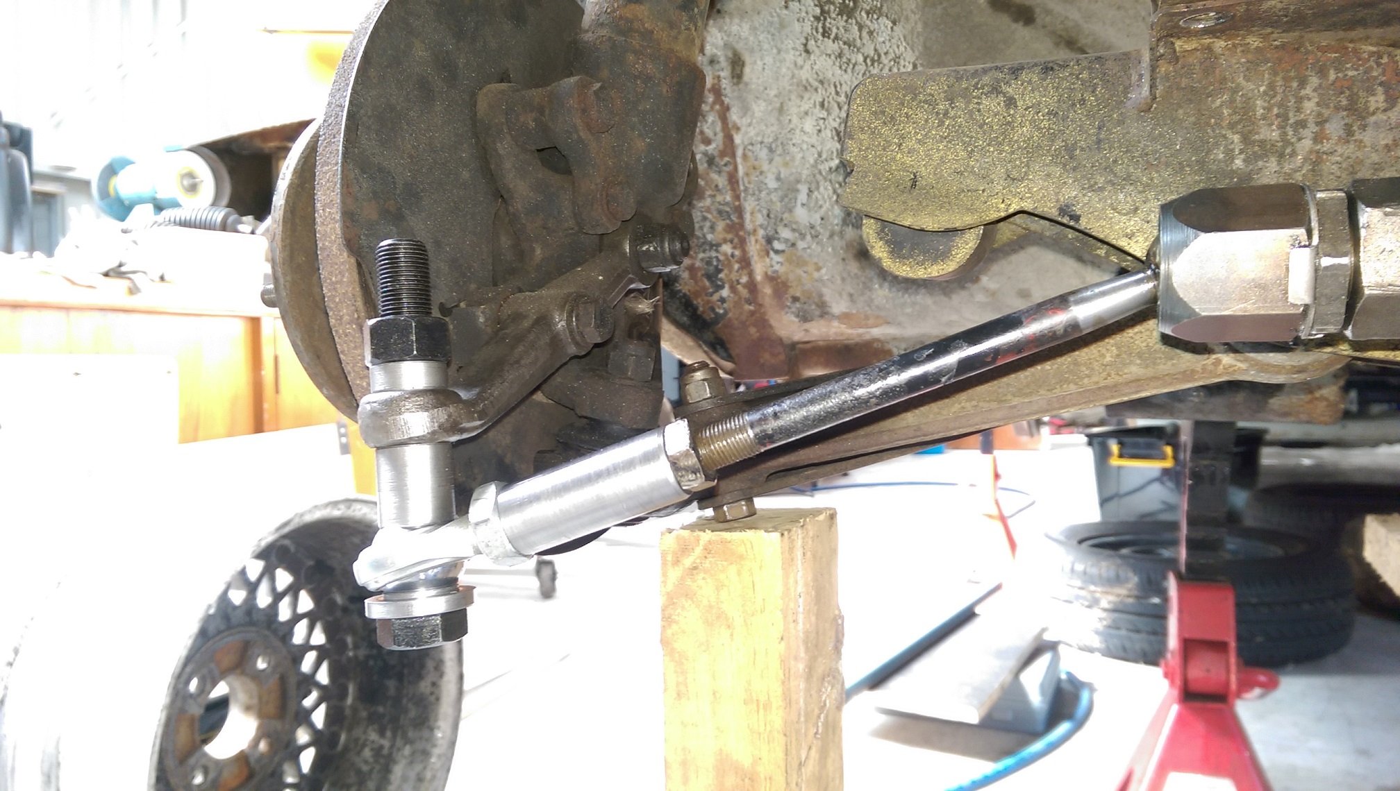
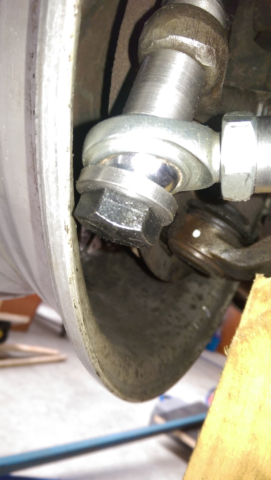
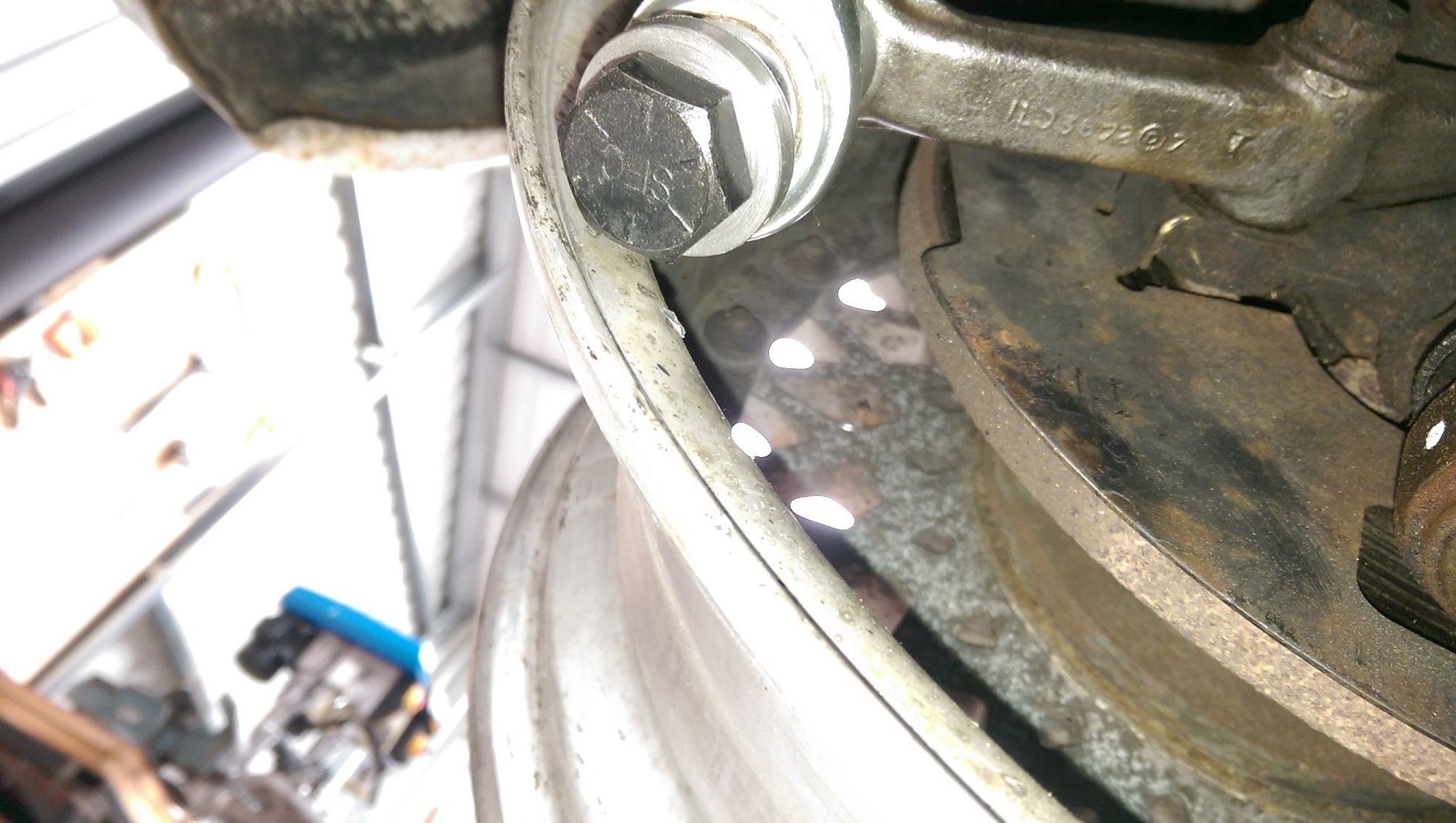
So I've got my spacer to put the rod end at the right height. I've got my "beefy washer" at the bottom to prevent pull through. I've got a Grade 8.8 bolt and the shank goes all the way through all the bits(the extra spacer at the top allows me to tighten the nut).
But that beefy washer and bolt head are now REALLY close to the wheel. I had to space the wheel out with some 3mm washers. So now I have 3mm clearance.
How much clearance is enough clearance?
I can space the wheels out further...
-
I get my belts from MyTools. They don't always have them available. But the green Zirconia belts are the only ones I've come across that hold together long enough to wear out before breaking. AFAIK, they are glued and taped. I use my power file mostly for cleaning up welds, and the sharp edges are pretty hard on the join. I tried the bunnings ones, but they fell apart so fast I may as well have put them straight in the bin. I've only ever seen the bosch belts in 60G, but I mostly use 40G for welds.
-
2
-
-
42 minutes ago, The Bronze said:
One of the bolt holes that hold my starter in place is shagged. Should i attempt to retap with the same thread or drill out and step up a size? It's imperial thread so retapping the same means buying a set, stepping up I could do with my metric set. But, prefer to do it right...
Regarding taps. I've recently been buying German Volkel brand taps. From CarbideNZ. They are quite affordable for what I think are quality taps. Miles better/sharper at cutting threads than the absolute rubbish "Frost" brand set I have.
-
2
-
-
- Popular Post
- Popular Post
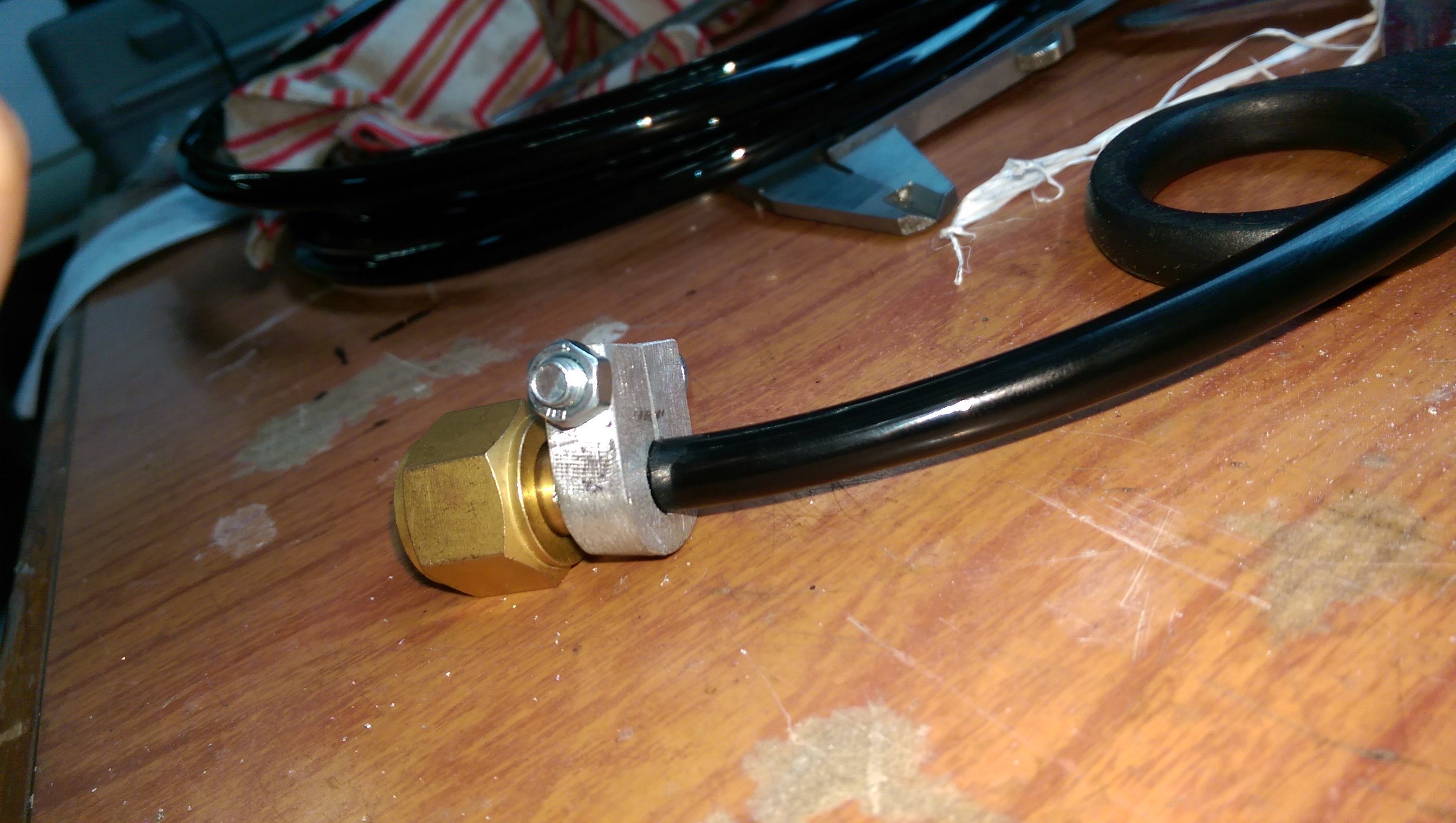
I needed a tiny hose clip, and I didn't have one small enough. I could have just bought one..... but I was expecting a courier deliver my new lawn mower, so didn't want to go out and miss it.
So I made one...
Works real good. After the mower arrived I did go out to get oil for it. I didn't bother getting a "normal" hose clip while I was out.
-
21
-
1
-
- Popular Post
- Popular Post
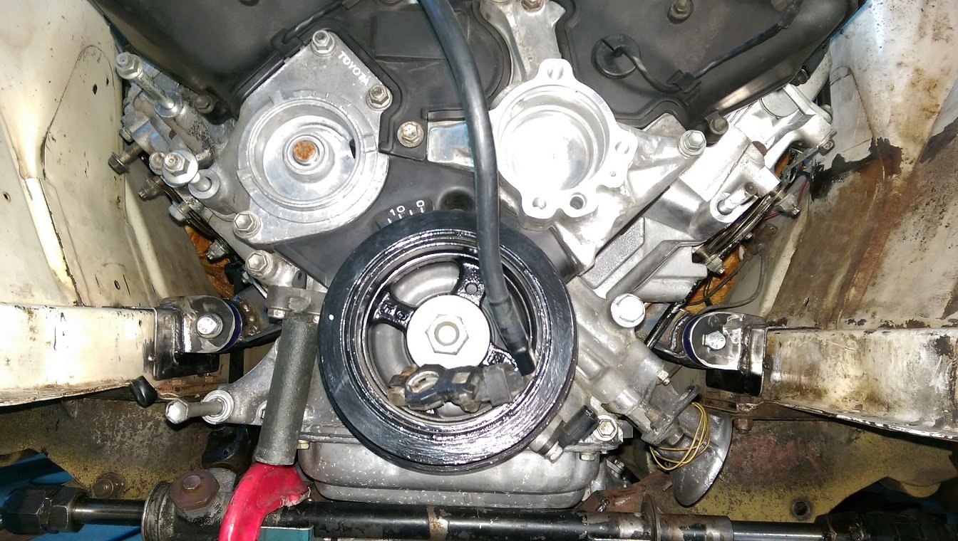
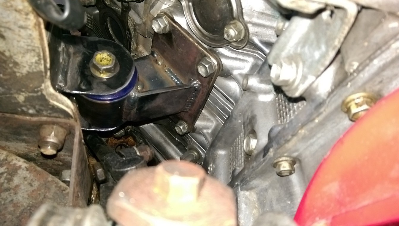
Aaand the engine is now self supporting. It sank a couple mm. I wan't sure if it was resting on the rack, but no, I can slide a thick bit of card between them. I'll be notching the sump, eventually, to get some more clearance off the rack.
-
15
-
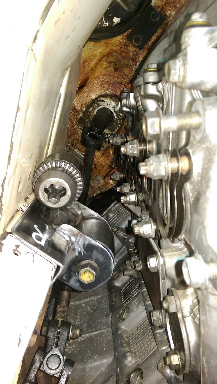
And the other side.
My auto welding helmet is naff. It gets waaaaay too dark and it's hard to see. Dunno if it was always like that.. But it's realy old now, so I've ordered a new/better/expensiver one.
It was a billion degrees, so I'm leaving it to cool before seeing if it still fits.
-
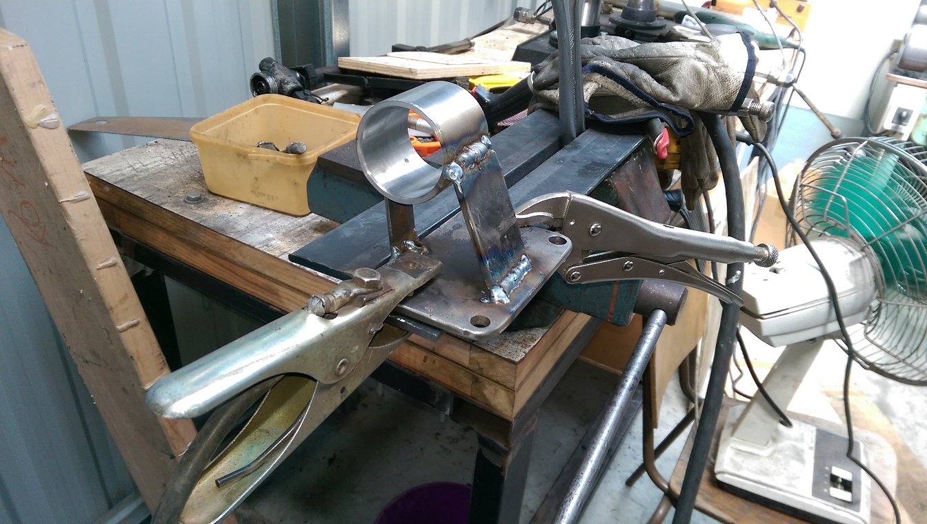
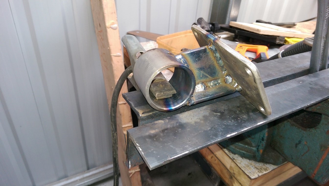
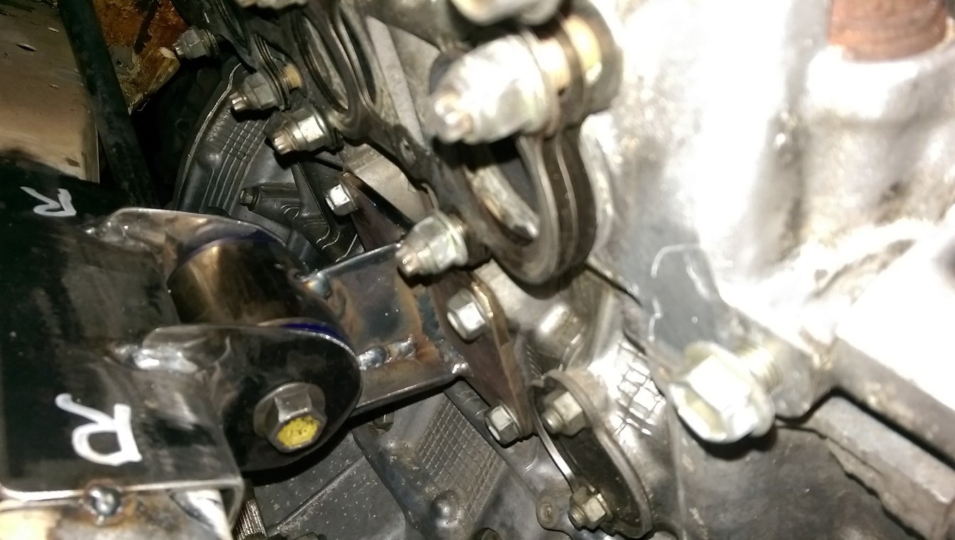
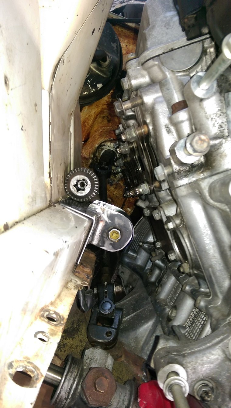
I've made the bracket for the driver side. I didn't want to make it too bulky and make it almost impossible to install the bolts. The welding warped the tube slightly, it's oval by about 0.5-0.75mm. Fortunately the bushes still fit okay.
I tacked a bit of 2.5mm flat between the tube and the plate to locate them, then unbolted it and removed the bushes so I could make the bracket from 5mm plate on the bench.
After letting it cool, I tested that the bushes still fit and the bracket was still the right shape to bolt back in. YAY, it still lines up with the holes!
I'll tidy up the welds a bit with the die grinder...
I've temporarily tacked the mount to the chassis rail so I know exactly where it needs to go for later. Because I need to remove the engine to get in there to clean it up for welding, then weld it.
-
9
-
-
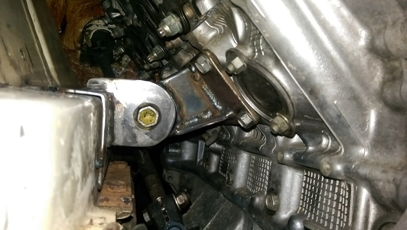
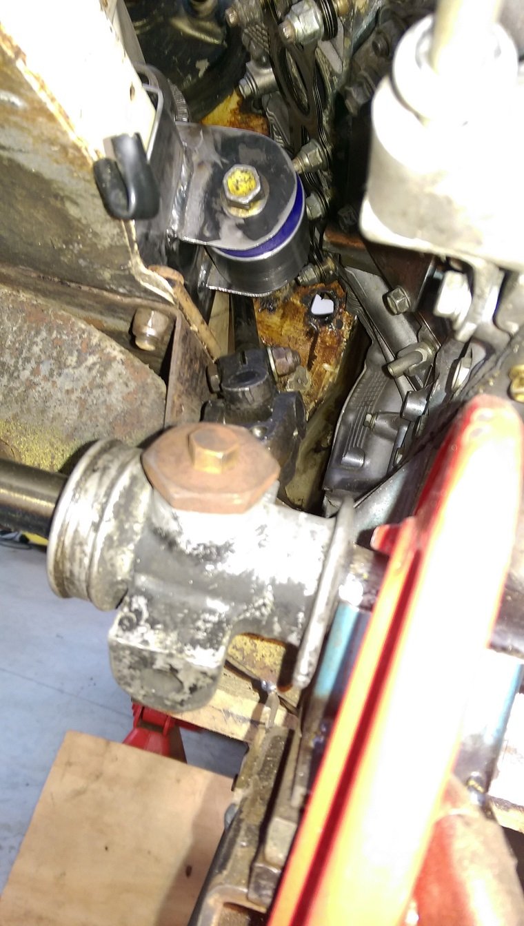
Fine then!
I'll just use this broken chuck to weigh it down.
I got a bit overzealous with the tacking and melted one of the bushes a little bit.
But it's okay, it's just cosmetic.
The engine mounting plates are now bolted down properly. I had to shorten the bolts in the lathe. They were a bit too long because the original mount was a really thick aluminium casting.
A bit more room for exhaust manifold. I'm afraid it's probably going to have to be a log style, there probably isn't room for 4-1, or 4-2-1.
This is as low as it will go. Any lower and it's too close to the steering intermediate shaft.
-
7
-
-
28 minutes ago, toy-mota said:
would i need to keep odo for a wof?
or i was looking at this?
frequency to voltage converter with a dc motor into the back
I've never had any problems with getting wofs. It's been like that for at least 4 years. You can buy speedos that take a pwm input and you get an odo. I think they are a few $100. I only used a tacho because I was looking for the cheapest possible solution, because racecar.
-
2 hours ago, flyingbrick said:
People should correct me if im wrong here but im sure even the guts from a tachometer could be installed behind ya factory cluster and fed pulses from the link to display speed 100% accurately.
Id just hotglue the guts in there and smugface
That's what I did. You just lose the odo.
-
1
-


Gav’s Honda N360
in Project Discussion
Posted
I think track measurement is tread center to tread center, not mounting face to mounting face. Both the Nissan S13 and Triumph 2500 track info I found was not face to face.