


Adoom
-
Posts
2,279 -
Joined
-
Last visited
Content Type
Forums
Downloads
Events
Gallery
Posts posted by Adoom
-
-
See my sight glasses....

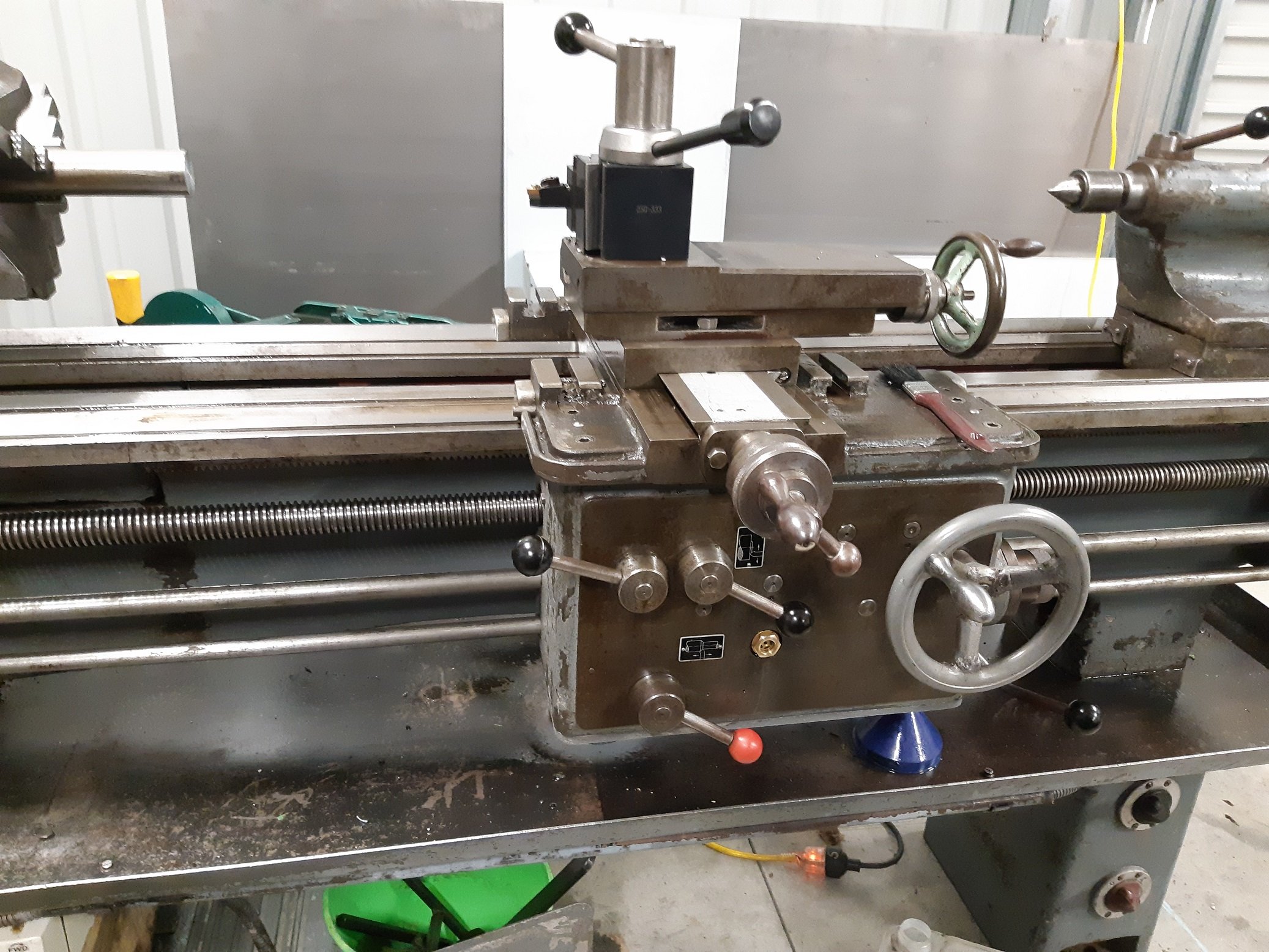
I also got an Aloris style wedge type tool post from EBay USA. It came with 7 holders. I thought it was a lot of money.... then shipping and unspecified "duty and taxes" got added, which doubled the price.
So I'd been trying to think of an excuse to buy a 3HP motor to upgrade the 2.2HP motor.
The 2.2HP had a noisy centrifugal switch.... The 3HP motor arrived this afternoon. After removing the 2.2 and finding it really hot, I realised the centrifugal switch was stuck on.... so the starting capacitor was always connected.
The 3HP is wired up now, it's much quieter. It was getting late...I still need to align the pulley and I want to see if I can find matching belts as they are slightly different lengths.
-
 8
8
-
-
I used silicone when I put it back on, after making sure all the..... selector forks? fingers? spades? blades?.... were in the appropriate slots.
I get to fill it with oil tonight.
-
2
-
-
The replacement china sight glasses finally arrived.
When I drained the oil out of the carriage, it didn't drain very well. I found that there was a thick layer of watery oily filth sludge in the bottom. So I unbolted the base plate to clean it out. Fortunately it cleaned up quite well. I also discovered that there was a broken spring. It had rusted at one end because it was under the sludge. I replaced the spring and its retaining screw.
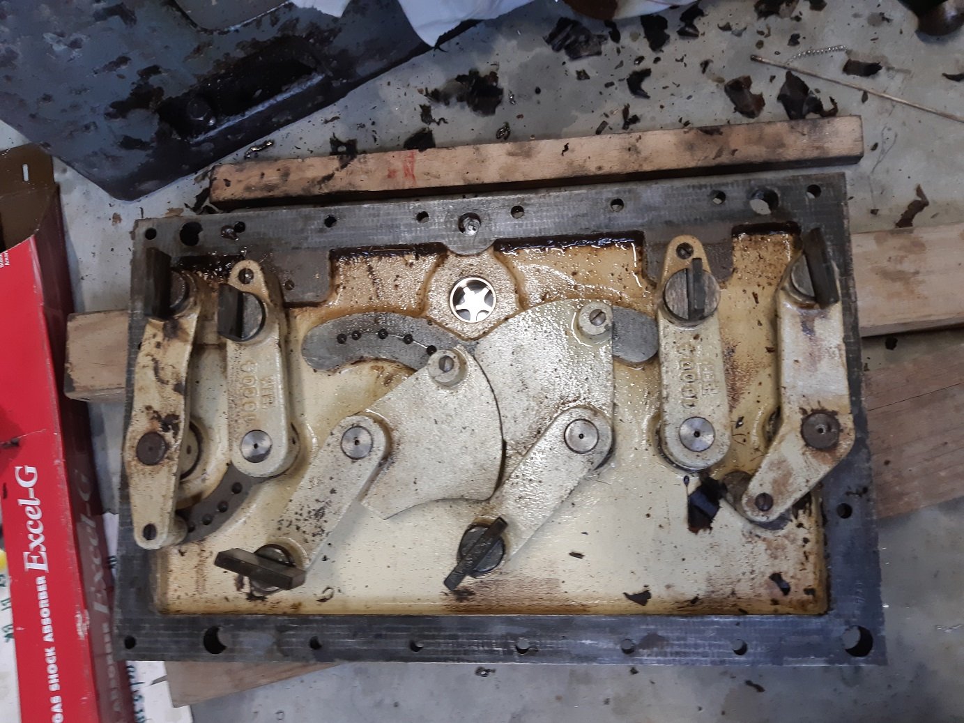
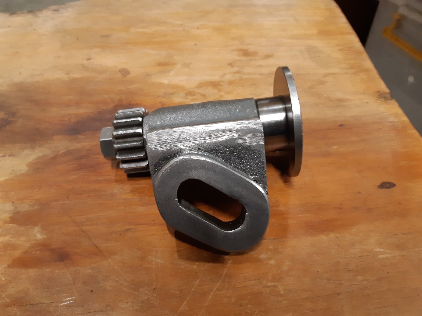
Tonight I tried to flush out the feed screw gearbox. I discovered it was pretty filthy too. So I moved all the levers to the left and removed the front plate.
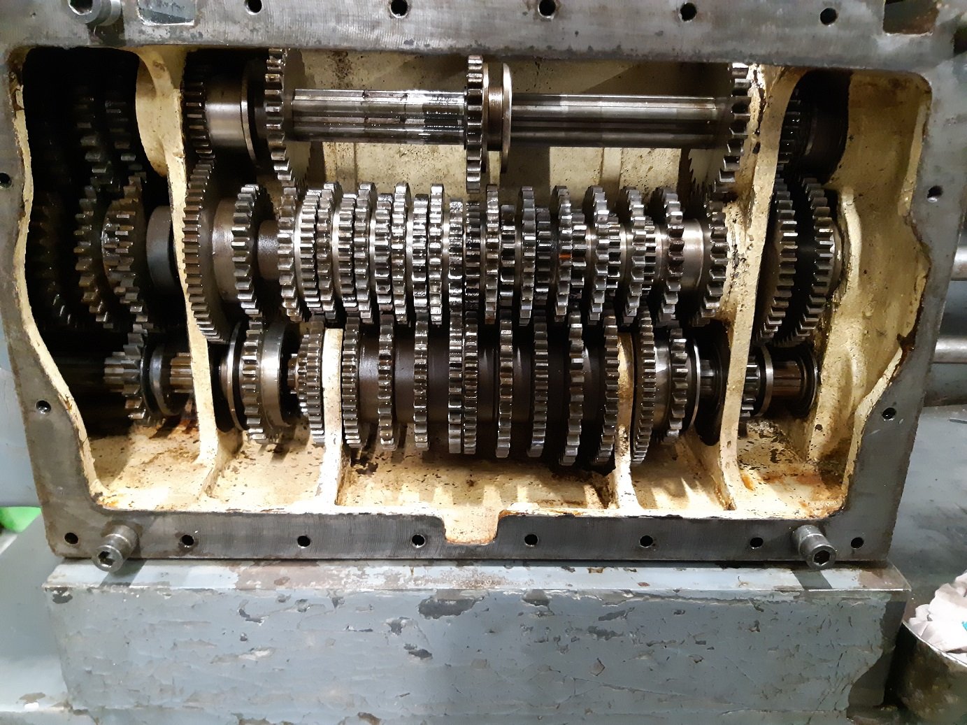
There's a couple of gears in there....
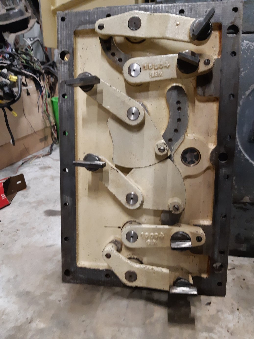
And then after cleaning.
There was a paper gasket. I'm not sure if I want to try make a new one, or just use silicone since it's probably not going to be removed again for many years.
-
9
-
 1
1
-
-
30 minutes ago, fantapants said:
#nailedit
Hey does anyone have any suggestions on how I can change the size of my pics ? The limit of 3.9mb per post means I can only get 1 pic, and a lot of the pics are saved as bigger.... any tips ?
I just open them in MS paint and use the resize option. 35% works for me. Still big enough for forums, but file size much smaller.
-
Was behind a truck this morning. It flicked up a tiny stone that went right into my helmet vent. What are the chances?! Rattle rattle. Rattle. Rattle rattle rattle. rattle rattle rattle rattle rattle.
I did eventually manage to get it out turning the helmet every which way to get the stone back to the vent hole.
-
3
-
 1
1
-
-
2 minutes ago, ~Slideways~ said:
Haha yeah I remember glittering prizes, what about blowing up sheep and ‘stop touching me’
I forgot blowing up sheep by constant clicking. I do remember "stop touching me".
-
1
-
-
Just now, ~Slideways~ said:
Got win98 machine all working, CD drive and sound.
Warcraft 2 with CD audio is awesome.
fck yeah:
Cool!
"glitteringprizes"
"fogofwar"...not sure if this one was a cheat....
-
10 hours ago, peteretep said:
new tyre each time? or repairable?
I got a puncture on a 3 month old tyre a while back, no one would fix it so had to get a new one. At least it was only $80
It was repaired with a plug from the inside last time. Hopefully it's the same this time. The hole is right in the middle of the tread, and it's tiny.
I've not had to replace the tires on this bike yet, not looking forward to finding out how much they cost, they are quite wide.
-
CB900 got a second puncture in less than 4 weeks.
First one was ~1800km ago... but what a PITA.
-
 2
2
-
-
1 hour ago, cletus said:
Anybody used water methanol injection for intercooling? post turbo.
I've been reading a bit of stuff which suggests it works quite well.
Have been looking at options on my car.
Have a water to air ic but it's going to add quite a lot of weight and complexity
Air to air also have but the bodywork covers a lot of the core plus would lose bonnet catch
It's not going to be a daily or very often so I dont think the methanol required is going to be a big expense
Yes. It was very effective. Especially after the tuner replaced the water with 100% E85. I think there might have been ~10 degree temp drops after the injector.
But, the jets that came with the Aquamist system did not supply a consistent/repeatable amount of E85.
So I replaced it with an inline fuel pump and additional injector and it was retuned. When the E85 injector was running, it reduced the 'normal' fuel at the primary injectors.
It was reliable... for a few weeks/months until I took it to a track day and something failed with the E85 system. Since the ECU had no way to know there was no E85. the fuel mix went REALLY lean and shit melted.
That's my story.
-
2
-
 1
1
-
1
-
-
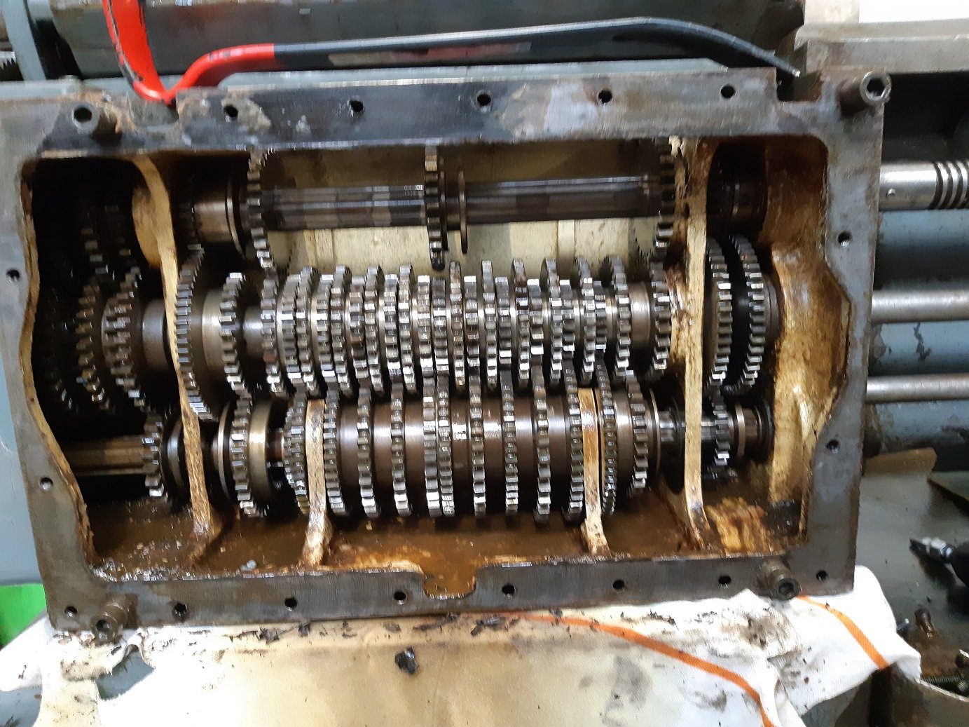
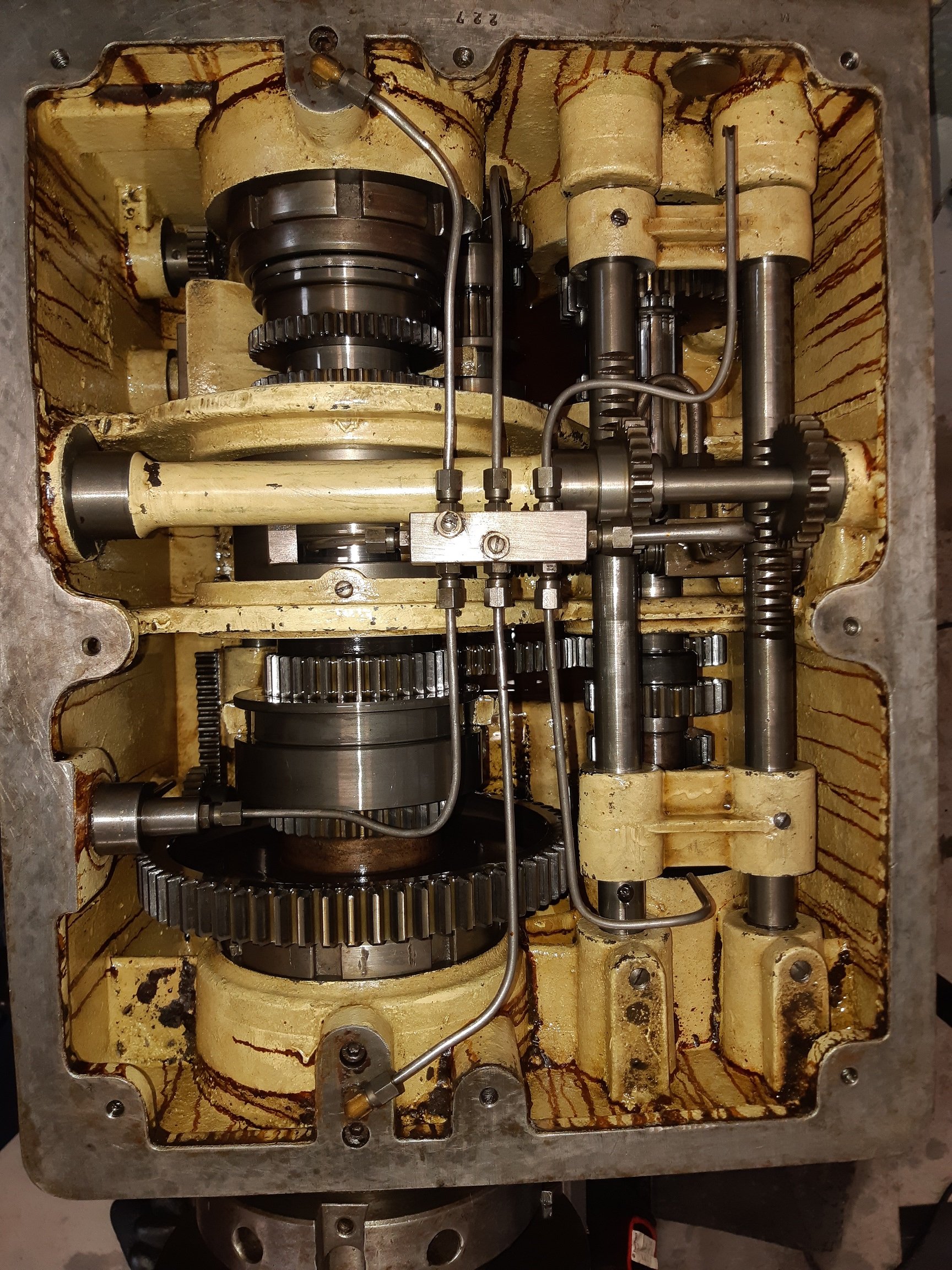
I took the lid off so I can de-rust it.
Looks okay in there. Everything is oily. There's no obvious wear.
The brown/orange streaks are not oil, it's almost like dried varnish. I suspect it's some kind of liquid gasket/sealer.
-
7
-
-
These guys had what I needed. https://www.tinkr.co.nz/
-
On 01/11/2019 at 10:22, Muncie said:
had an exact same one at my old work which has since shut doors wonder if its the same machine.
Would you know what oil it needs for the headstock? The Meuser site only has two kinds of oil. No brand name ISO VG 22 for the headstock and feedscrew gearbox. And ISO VG 220 for the carriage and ways.
I've found Cimglide 220 for the carriage. I have no idea how much it takes...
But I'm just getting confused trying to find an ISO VG 22 for lathe gearboxes.... I keep finding "hydraulic oil" in that viscosity..... is it the same thing????
-
Fiiiiiiiiiiiiine! So I linished the plates on the bench grinder to remove the slag so they would sit flush against each other.
Then I lined up the teeth and clamped it together with the bolts.
Then turned the tig down to 50 and ran it across the back a few times to glue them together.
It bolted up okay.
It's kinda works. Like it will stay up if I lift the arm. But it falls down as soon as I turn it on.
It would probably help if I sharpen the little plates that engage on the teeth so they fit better.
-
1
-
1
-
-
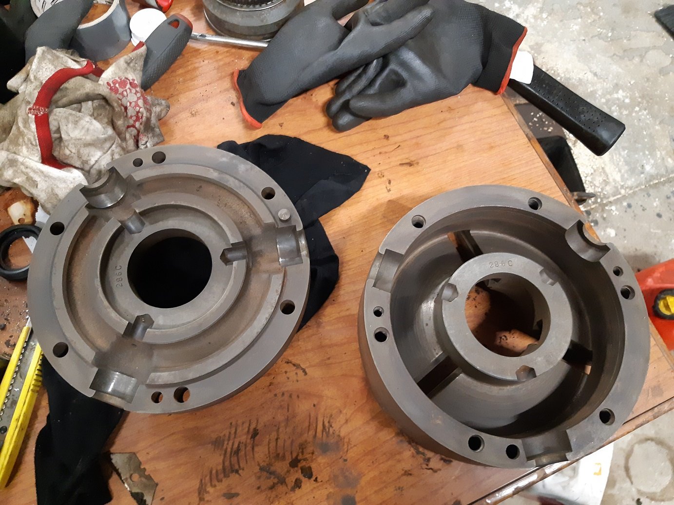
- Popular Post
- Popular Post
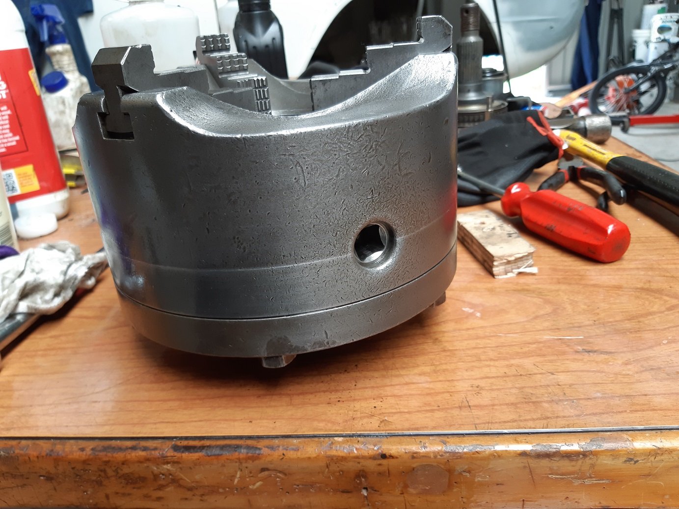
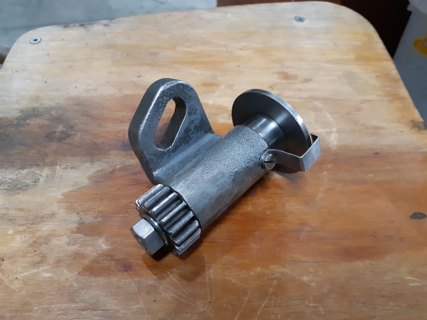
I lightly sanded some of the machined surfaces with 400 grit to get the rest of the black off.
It opens and closes smooth as now. It had to force it in some spots when I took it apart.
-
13
-
26 minutes ago, datlow said:
M33x2
NZ$ 0.55 | M12/14/16/20/22-M60 Metric Male Aluminum Oil Sight Glass Window Use For Air Compressor Lathe
https://s.click.aliexpress.com/e/elK1fNfKfor the other two that’s pretty close to 1/2 and 3/4 bsp? Bung them in with some sealant?
Close...ish. I found brass ones which would suit the lathe more than aluminium I think. For $26 I'll give it a go.
-
2 minutes ago, Mr Vapour said:
Sweet. I have a Orion coal range that I want to derust. I can't be arsed blasting it. Was planning on using a lap top charger.
That would probably work. I got my Bicarbonate of soda from Mitre10. It's with the laundry powders. It's called laundry soda or washing soda or something like that. It looks like almost clear, big crystals.
-
2
-
-
1 minute ago, Mr Vapour said:
Looking good. What power supply are you running on the bath?
It's just a cheap battery charger. I'm not sure how many amps it's doing. I have to submerge my whole hand before I can feel the pulsing
-
1
-
-
So these are the oil level sight glasses. They are plastic. They were too dirty to see through.
The 3rd one, from the headstock, was leaking enough to need a bucket. It was broken and it wasn't pressing on the seal properly. Removing it made it much much more broken.
The 4th one, from the carriage, was leaking a little bit because it was broken. It came out without more damage.
The first one is from the threading gearbox. It could be reused. I managed to clean it enough to see through.
The 2nd one is from the headstock, but it lets you see that oil is flowing and the oil pump is working. It's broken, but still seals. It's pretty hazy though.
All the o-rings are hard.
Those stars live inside the oil level sights so you can see the oil against a white background.
They seem to be proprietary. Yay....
The threads are quite coarse. M33x2.0mm, M26x1.75mm and M21x1.75mm.
All I've been able to find are 1.5mm pitch.
I'm contemplating popping my thread cutting cherry and trying to make something that will take an inexpensive generic sight glass.
I just had a thought.... I could ignore the thread and just silicone some perspex discs into the holes!
-
2
-
-
- Popular Post
- Popular Post
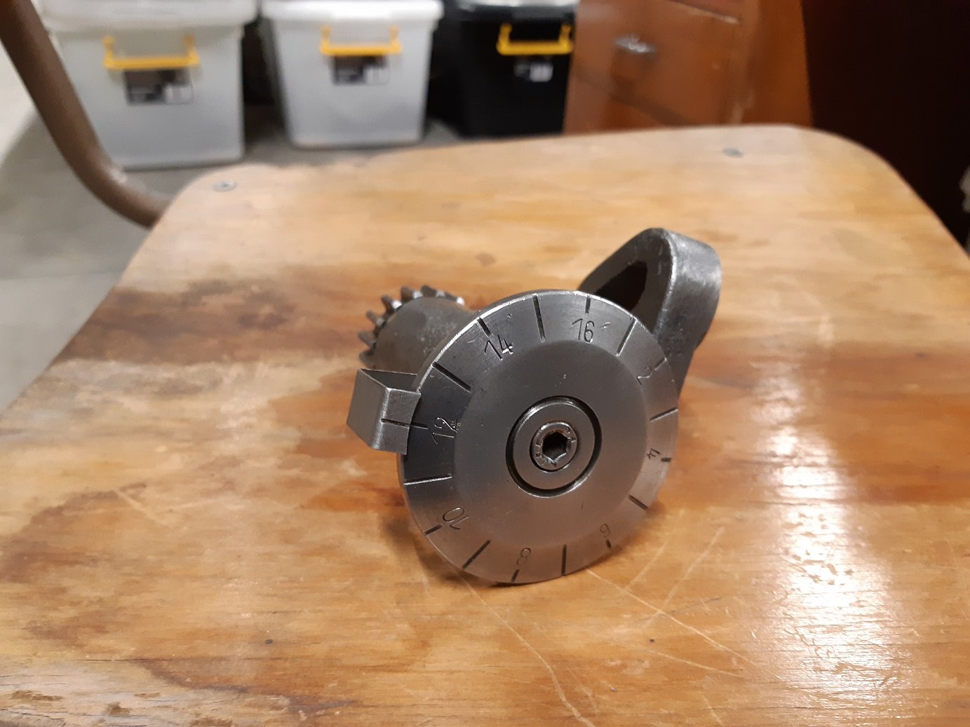
Clean. And I straightened the.... pointer bit. There's a little bit of paint still on it, but it's good enough.
-
10
-
-
1 minute ago, flyingbrick said:
hey did this work in the end?
It's definitely still sitting in the small thingies drawer. I should probably finish it, over a year is probably long enough.
-
1
-
-
- Popular Post
- Popular Post
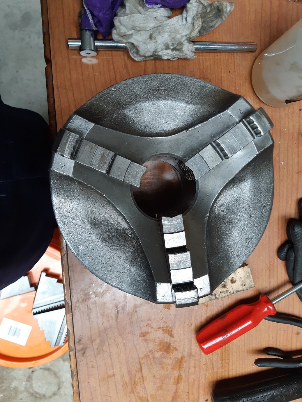
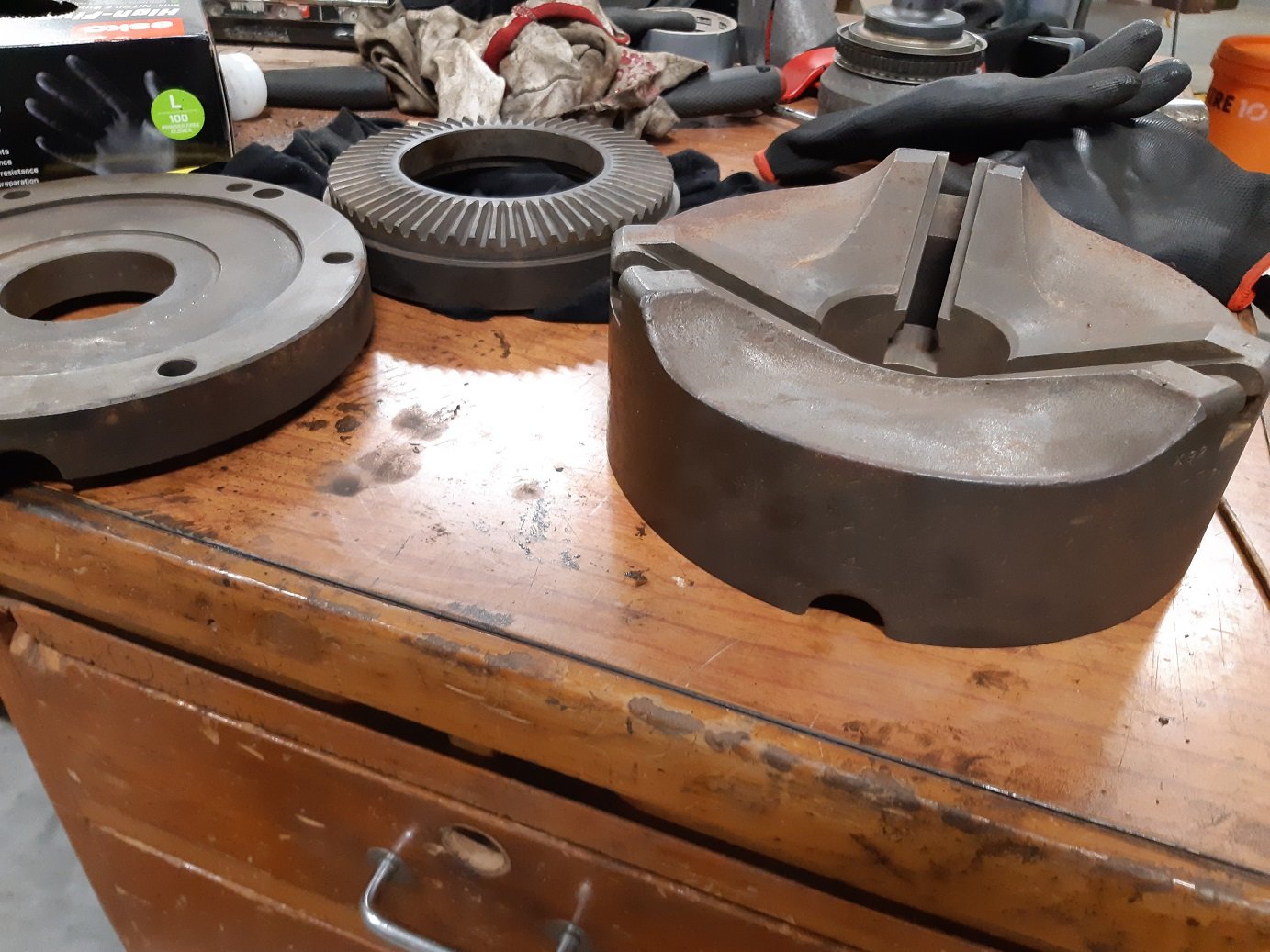
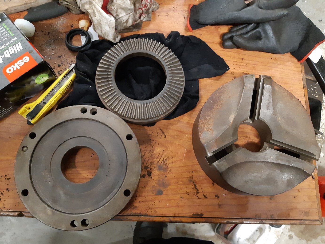
28 minutes ago, flyingbrick said:Interesting 3 jaw with the dished face. You are damn good at cleaning these parts up, many shops could take lessons!!
Thanks!
Basically it's just:
- Degrease. Because the electrolysis doesn't work so well if it's oily.
- Put in electrolysis bath for a day or two or several days. Each day, or whenever, give the sacrificial electrodes a scrub with the wire brush to remove the crusty shit so they work good again.
- Rinse with hot water.(I have a hot tap outside)
- Clean off black stuff with hot soapy water, scourer pad and wire brush. Most of it will come off with minimal effort.
- Rinse with hot water.
- Parts will start to flash rust as they dry.
- Blow dry with compressed air.
- Spray with WD40 to remove any left over water.
- Wipe with cloth. Much of the flash rust will wipe off.
- Sensually massage parts with oil.
- Wipe with cloth to remove excess oil.
-
11
-
1
-
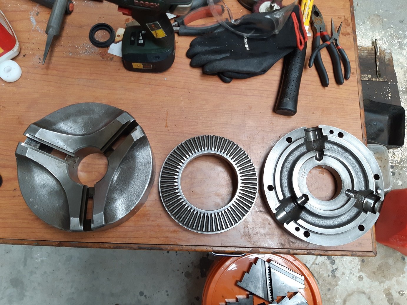
In the bath now is the 3 jaw.
I degreased and cleaned it with petrol. It was pretty filthy inside but otherwise seems okay.
It's a weird chuck. The jaws slide on an angle. It makes it stronger I think?
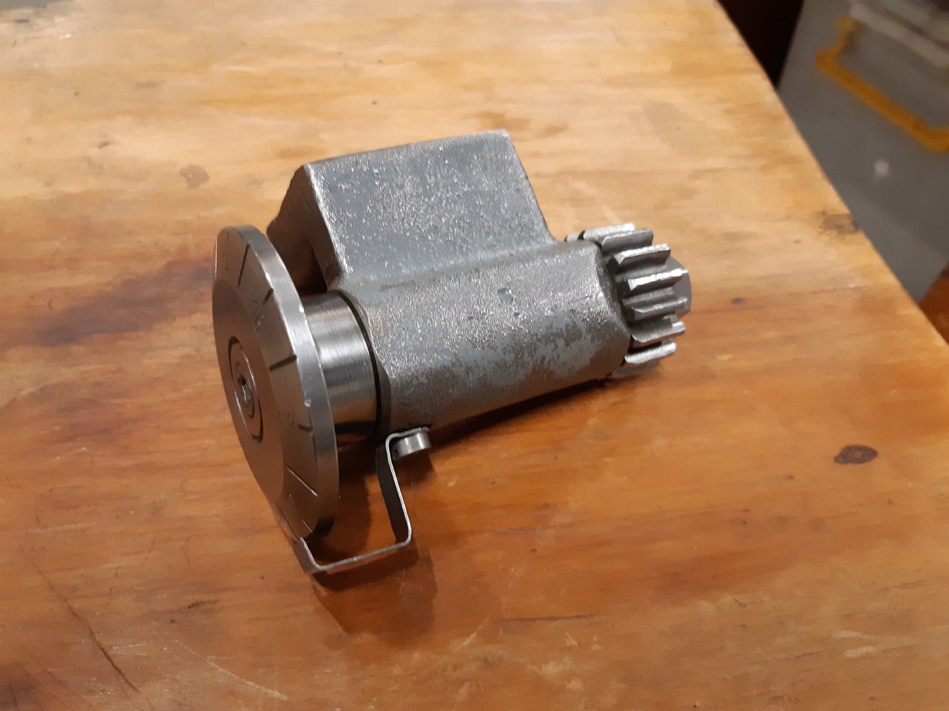
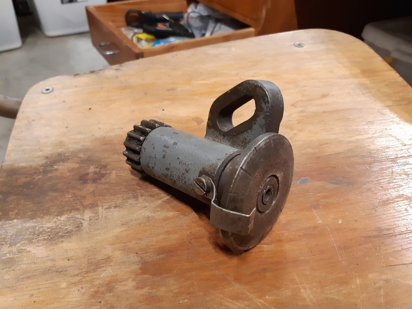
And the threading counter thingy. I've degreased it and put it in the bath too.
I'm running out of stuff to de-rust!
-
6
-
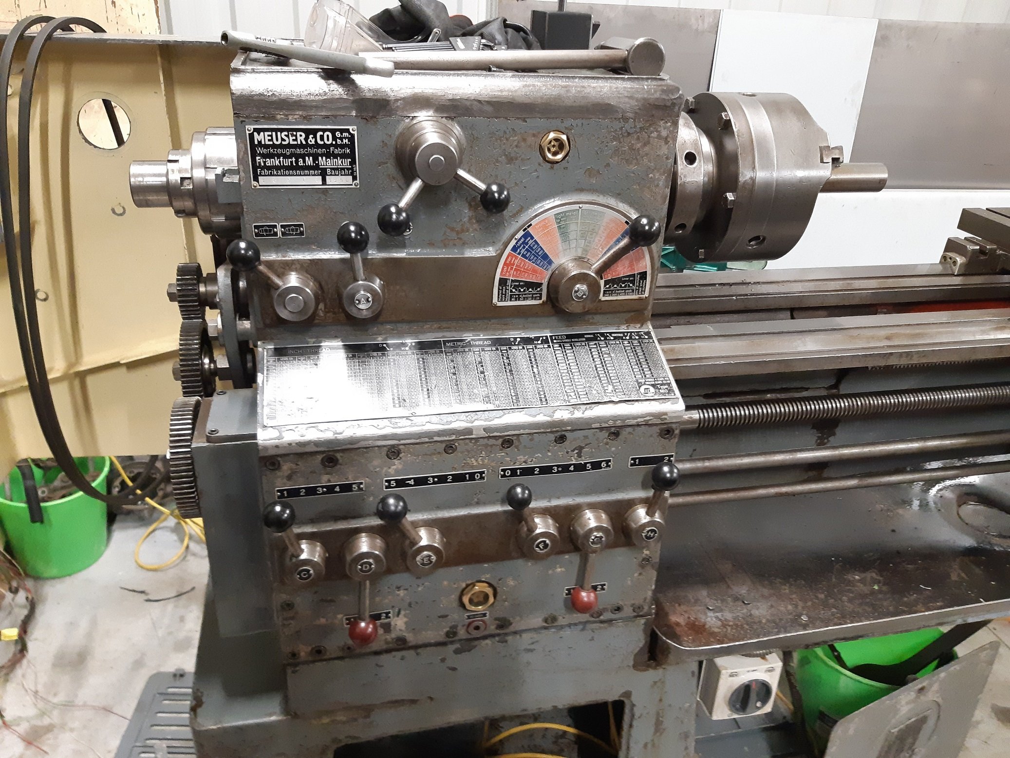


Adoom's 1956 Meuser Lathe(Big German)
in Other Projects
Posted
I fucked up.
When I wired in the forward/reverse switch, it wasn't obvious how to include the over current switch...
Here is my $260 mistake.
The smoke was/is acrid as fuck. Really burns the eyes.