
- Popular Post


Adoom
-
Posts
2,279 -
Joined
-
Last visited
Posts posted by Adoom
-
-
Found what was causing the intermittent wire feed when I used 0.6mm. Turns out the drive motor can move a little on it's mounting bolts, 10 or so years of tightening the roller had shifted the drive wheel down a little bit so the mechanism bottoms out before it's tight enough for the thinner wire.
Fixed now. YAY! It was so frustrating.
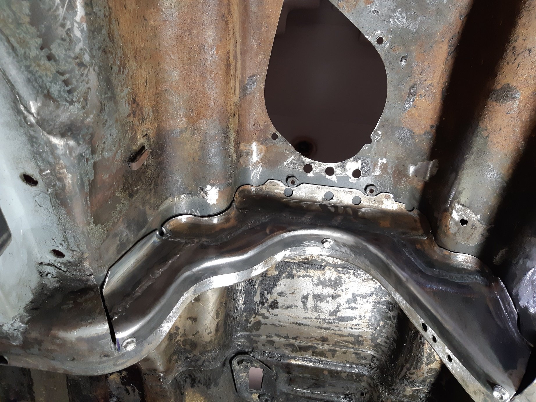
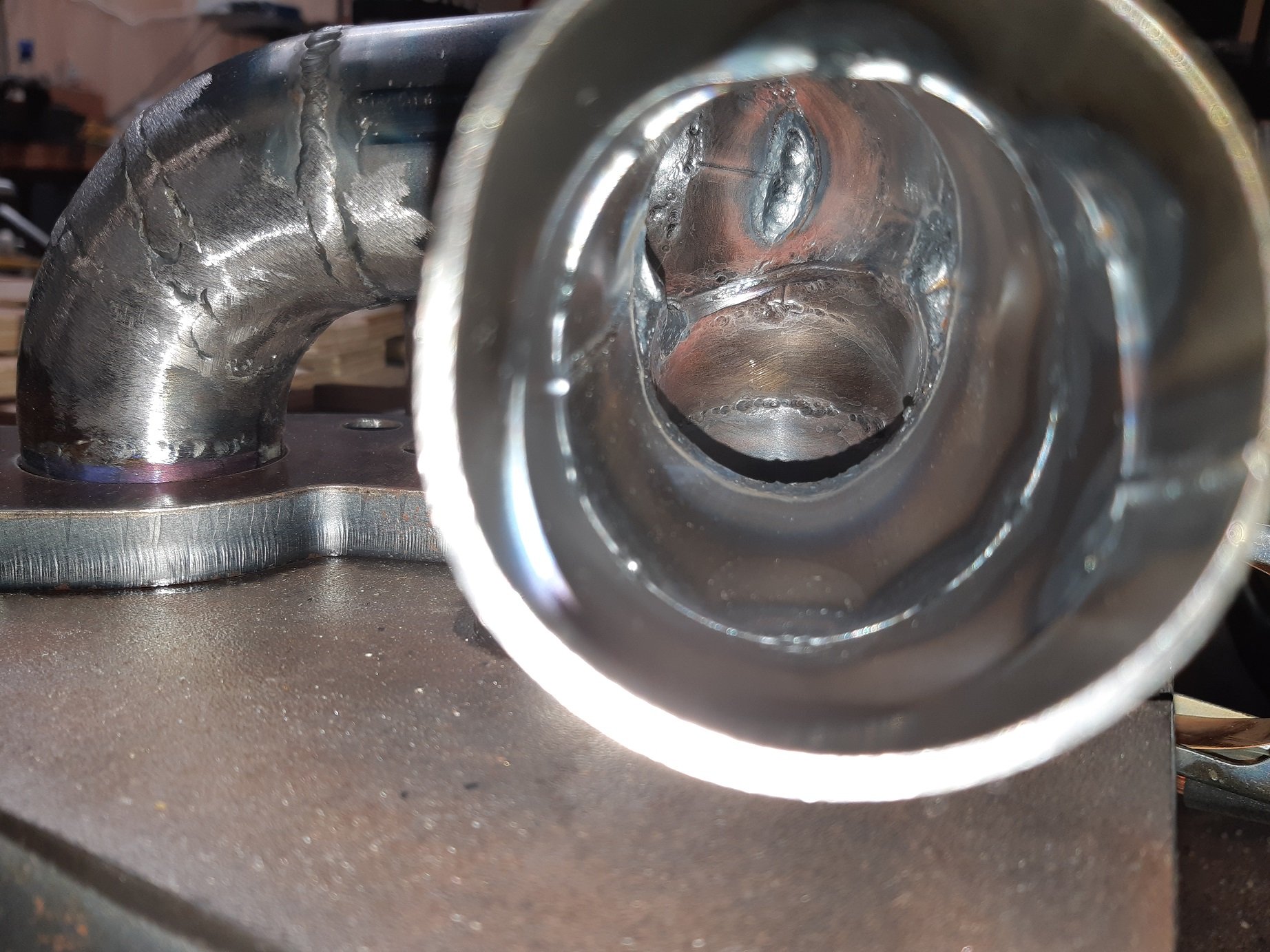
Zip zap. Got rid of the ugly seam flange thing.

Welded inside first.
Then cut off the flange and welded the outside. Then linished and used the knotted wire brush to show up any gaps I missed. Then weld and repeat until no gaps.
I also welded up some rivet and bolt holes that are no longer required. I need to cut some round patches for the original heater pipe holes because I've relocated them.
I've also welded in the modified cross member, but the photo was blurry. I still need to make some filler bits for the 'corners'.
-
 9
9
-
-
- Popular Post
- Popular Post
Since I had decided on the path the extractors needed to go to miss the steering, I decided to take the engine out and do the rest of the extractors on the engine stand.
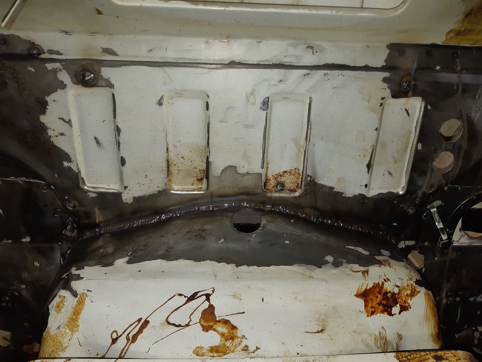
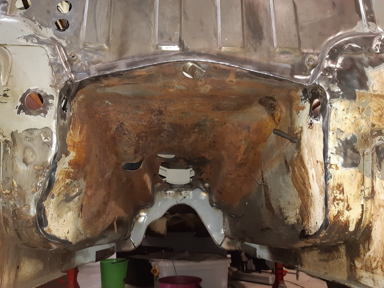
I have some stuff to do while it's out. Like fix the one rusty bit on the firewall. Clean up the rest of the tar seam sealer. Remove the big seam where the firewall joins the transmission tunnel, this will get me a bit more room around the back of the engine.
I also cut out part of the cross member that makes it really hard to install the gearbox and temporarily tekscrewed in the modified section I made several posts back.
Was a filthy job. I was getting showered with dirt and grinding dust. Fortunately it was cold, so I could wear overalls and a beanie and safety glasses and ear defenders without dying of heat exhaustion.
-
10
-
Is it 1/2" Whitworth? Slightly larger than 1/2" UNF.
-
10 minutes ago, rusty360 said:
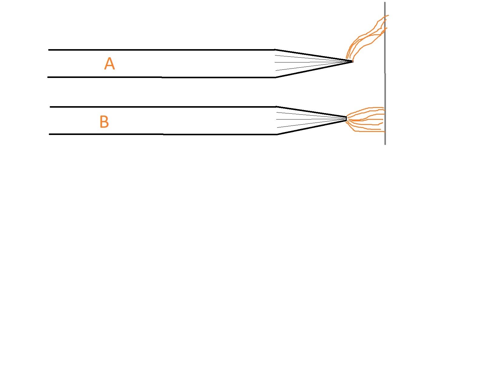
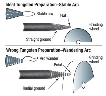
Which way are you grinding your electrodes? The grind lines need to run down the length of the tungsten not around and around. For steel tig welding electrode should be a sharp as possible and the ground section about 3x as long as diameter of tungsten, has always worked for me.
I was grinding them sharp. Like in image 'A'. I also tried different tapers. But the arc would always fuck off to the side, it didn't matter what what current level.
Then I ground them like 'B' with a flat on the end, it's less than a mm. That has given me a consistent arc.
-
7
-
-
This shit takes fucking ages to do. There's no way I could afford to pay someone to do it.
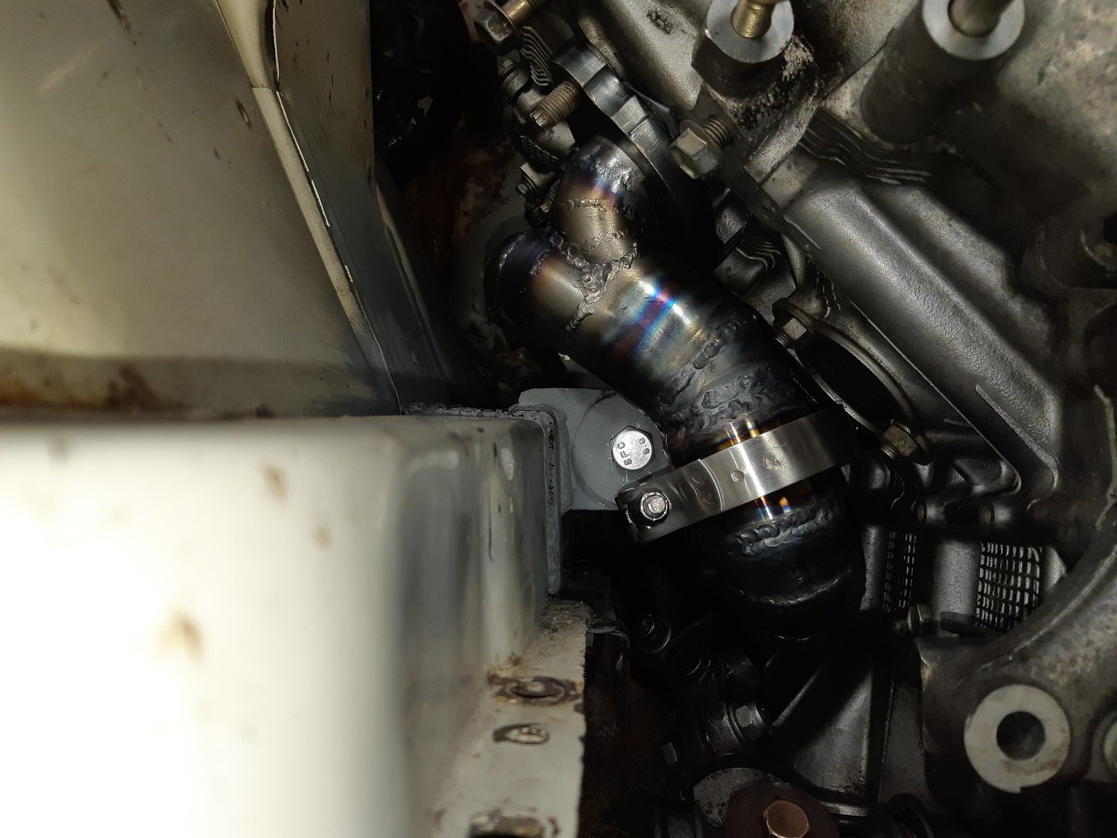
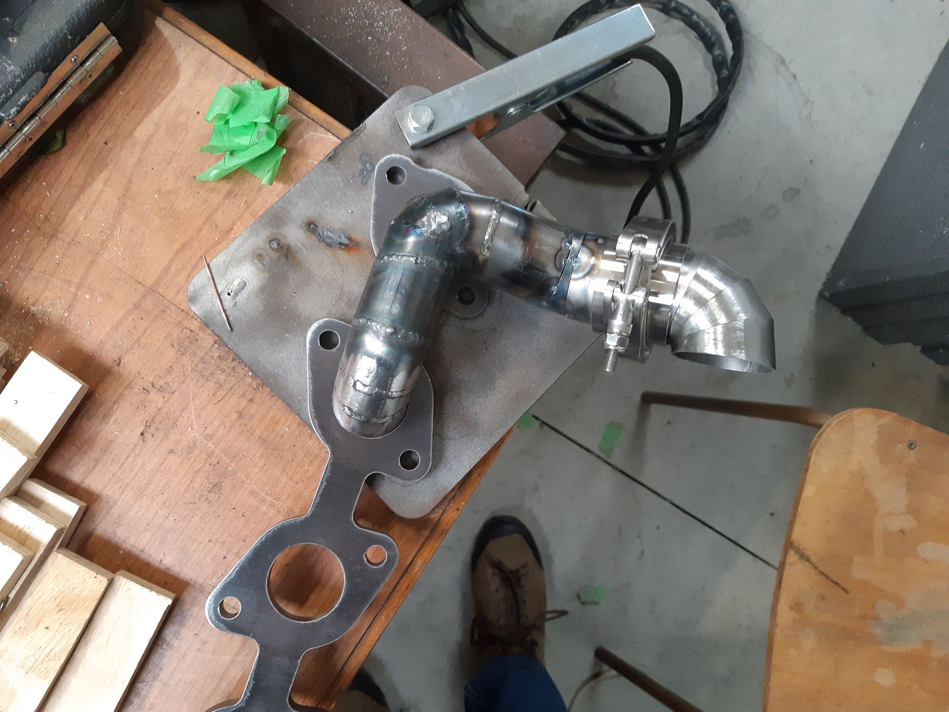
I made enough room to get at the engine mount bolt. Once the pipes are welded to the flange, I have to lift the engine slightly to get the flange over the studs because it hits the chassis rail. I'm aiming to be able to remove the engine with the exhaust attached.
I don't even get a straight run through this gap. To keep clear of the universal, that pipe is rotated towards the block, then I can use ~25mm straight before a 14 degree bend. Then a bit more straight I think.
-
8
-
-
9 minutes ago, SOHC said:
Do you have a magnet close by or you welding in a conner? DC gets arc blow like there is wind blowing it, AC won’t do it
The issue was my grind on the electrode, I'd ground it to a sharp point. I ground a small flat on the end and the arc was much better.
But I did think of the magnet issue. I thought it might have been my fitbit, so tried taking that off too.
-
1
-
-
- Popular Post
- Popular Post
I've made a start on the convoluted snake nest that will be the exhaust manifold.
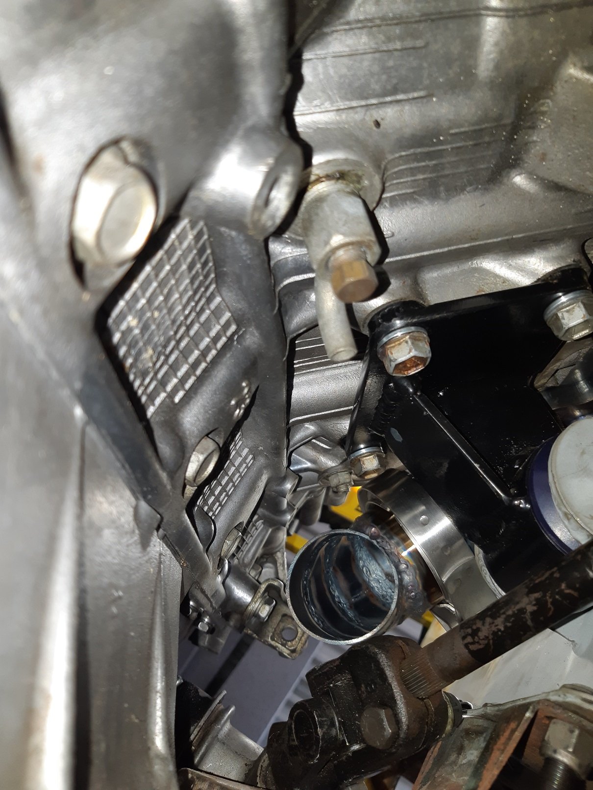
The steering shaft and engine mounts are leaving me with fuck all options. I also have to avoid blocking any bolts that will make it impossible to install the exhaust.
That rear stud needs to be replaced with a bolt, it only clears the universal joint by a few mm.
The only direction the two rear ports can go is under the steering shaft. To do that I have to make pie-cut bends, the smallest donuts are too big. They will merge right away into a 2" pipe, then there will be a v-band clamp.
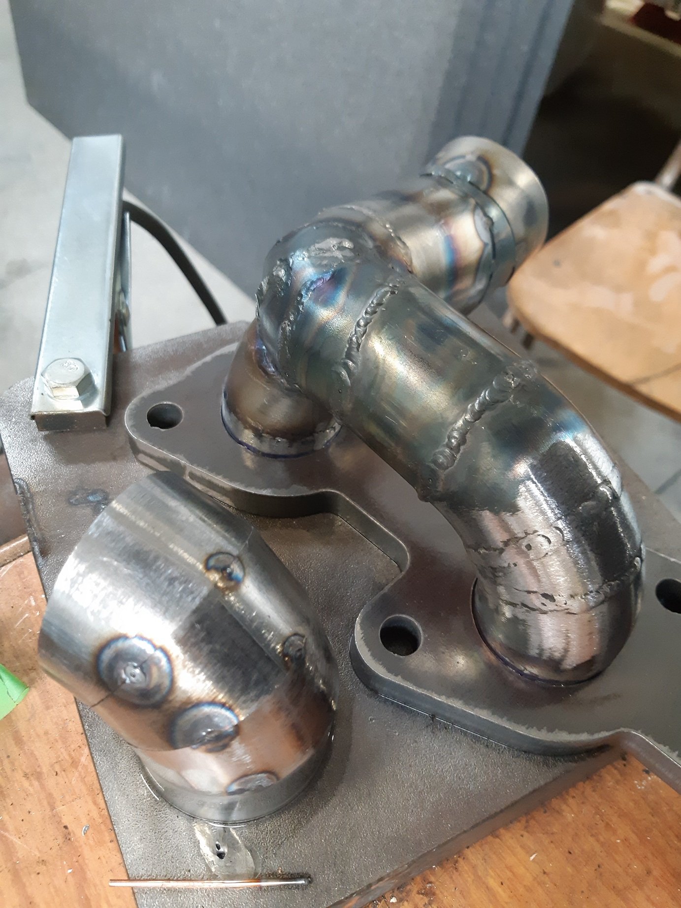
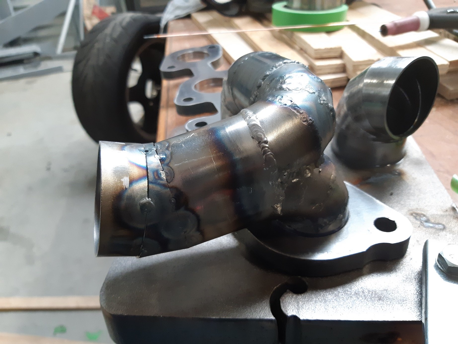
The two front ports also merge into a 2" pipe then there is a v-band clamp.
There will be a 2" pipe running under the engine mount that joins the two v-bands, then crosses over to the other bank in the gap between the sump and bellhousing.
There will be another v-band just before the cross over pipe merges with the 2" pipe from the other bank.
The two 2" pipes from each bank will merge into the final 2.5" pipe.
Here's my start on the piping for the front two ports.
The v-band won't be exactly there, it's just precariously balanced for the photo.
My tig welding has improved a little since I started.
-
12
-
- Popular Post
20 minutes ago, Muncie said:Earth other side of pipe.
I tried relocating the earth so it was connected to the pipe rather than my "welding table"(a bit of 25mm steel plate).
It appears that grinding a small flat on the end of the electrode has sorted it.
-
10
-
11 hours ago, cletus said:
Polarity is correct?
Yes, positive ground.
10 hours ago, kws said:I have ground them like the top picture, but I have a point, not a flat. I have come across conflicting information whether there should be a point or a flat end at low currents.
I will try it with a flat tip today. Hopefully that's it,.
-
So I have a DC tig welding issue. I'm still new to tig.
I'm trying to weld some mild steel exhaust tube, so it's 1.6mm thick.
The arc is not shooting straight out the end of the electrode, it's pissing off at an angle, about 45 degrees. If I get it REALLY close to the puddle, it looks like it's straight, but really, it's still at an angle.
I'm using 30-35 amps.
I've made sure I have a good connection with the ground clamp.
I've cleaned the work with acetone.
I've tried striking an arc on a thick steel plate and turning up the amps to 170. But it's still doing it.
I assumed it was the grind on the electrode. I tried regrinding it by hand. I tried turning it in the drill while grinding it on the bench grinder. I've tried a really sharp point and a not so sharp point. I've tried a different electrode. I've tried a shorter stick out. It all seems to make no difference.
WTF else should I try?
-
Why?
820kg. Scales at Silverstream landfill. Many years ago. A fair bit heavier than standard.
AFAIR, spec at that time was.
KP60. Square headlights. 4 Doors.
Road legal.
CA18ET
S12 FSW71B
T-series Diff with drum brakes
10.5" X 18mm vented front discs. Alloy calipers.
-
I too was drinking coffee more than I was drinking water. Went to the doctor with dizzy spells. Doctor said I had made myself dehydrated which caused quite low blood pressure. Changed to only 1 coffee and 2L(4 big glasses) of water over the day, fixed the blood pressure in about 10 days.
Regarding crutches, when I had a broken leg, I found scooting around on an office chair with wheels was really handy if I needed to carry something like a plate.
-
6
-
 1
1
-
-
Aaaaaaand I wired up the switches for the big forward/reverse lever on the carriage. So now I can make it go forward/stop/reverse with that lever.
I'll go to jaycar on Saturday and get a 10K potentiometer for the speed control and maybe a box to put it in.
-
3
-
-
Can you get another case and stack them?
-
1
-
-
Correct size belts arrived at lunch today! It's ALIIIIIIIIVE!
It's got no problem with a 1 second acceleration time in all the gears. Okay I'm a little scared to crank straight to full speed in top gear. The speeds on the gearbox are for a 1400rpm motor and my motor is 2800. So the 760rpm top gear is actually 1510rpm.
I had to increase the decelleration time to 6 seconds to stop it getting an over voltage error. If it goes over voltage it cuts the power and lets the motor freewheel to a stop.
I'll try do some wiring of the remote switches on the weekend. But I really should be installing the garage insulation cause it's in the way of everything.
-
4
-
-
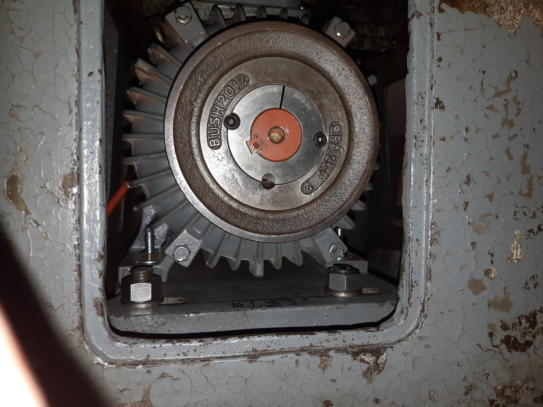
Dang it!
The new belts are way too long. I cannot lower the motor far enough to take out the slack.
Lesson learned, now I know belt lengths are listed by inside diameter. The way I measured the length I needed got me the outside diameter which is 40-50mm different.
Ordered more new belts, hopefully they send them today and I should get them tomorrow.
WAAH!
-
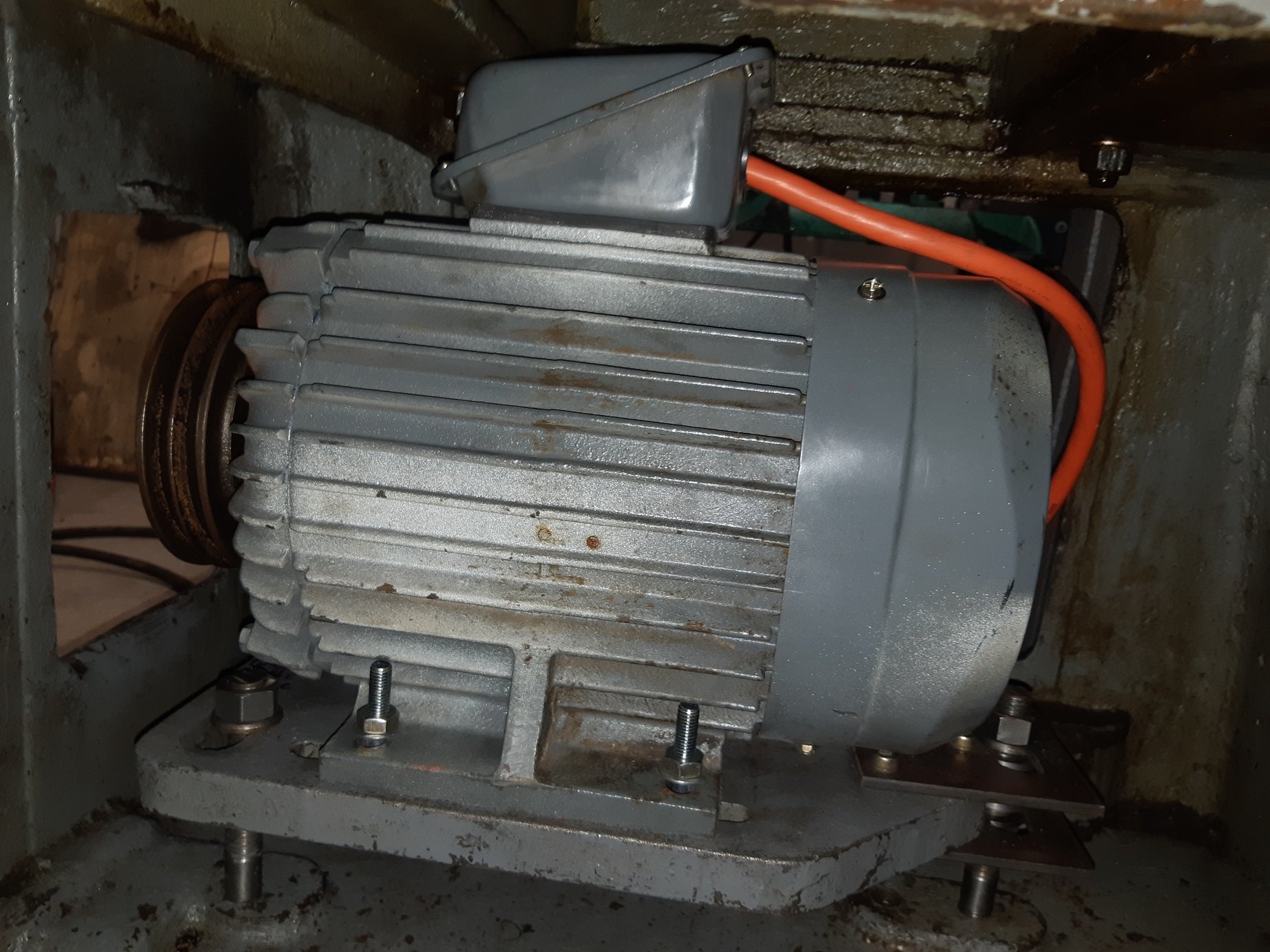
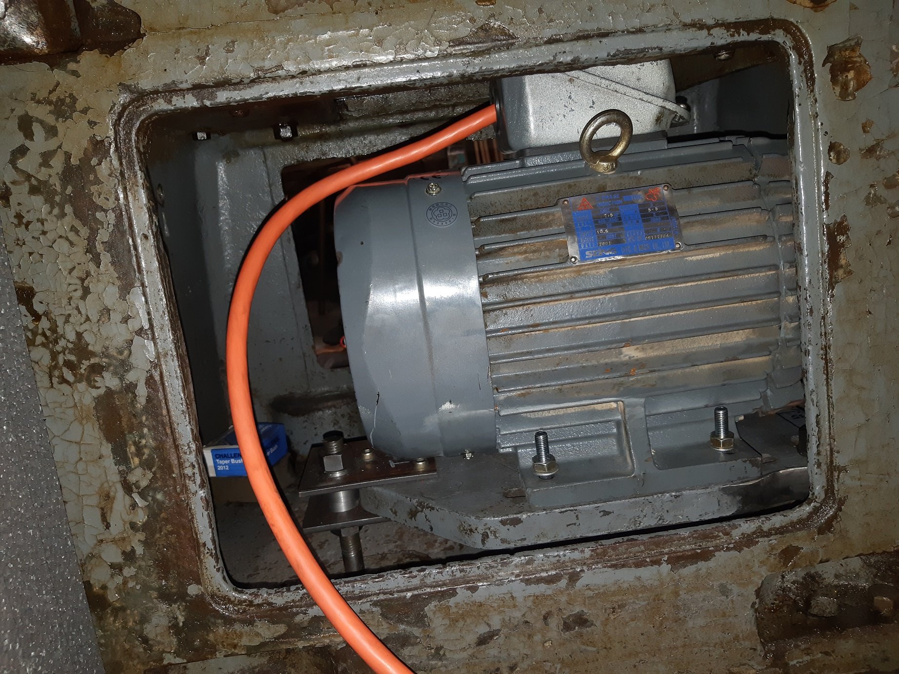
It fought me, but I managed to get it in there. It juuuuust fits.
I had to chop the big studs down to move get the pulley in the right place.
I found that the terminal box on the top of the motor could be reversed which gave me about 20mm extra clearance at the top.
To get it through the door I have to wrestle it in on its side then lift it back up. It weighs about 40kg.
I could not get the motor high enough to use the original belts so I have ordered some longer ones. Hopefully they should arrive tomorrow and it will be alive again.
I still need to wire the big forward reverse switch lever to the VFD and get a potentiometer for speed control and stop switch.
-
5
-
-
So I had a go at programming the VFD. Entering the motor specs and changing the acceleration and decceleration times.
I changed the accel from 20 to 2 seconds. It had no problem with that. But it may be different with a load.
I tried the deccel at 2 sec as well. Part way through it cut the power and showed a fault code. So I changed it to 4 sec which it was happy with. I'll have to look into how to use a braking resistor.
-
2
-
-
25 minutes ago, NickJ said:
Ramping down fast needs an external load no?
Possablery.... It does have terminals for braking.
I'll have to have a go at deciphering the engrish manual.
-
So with Covid Level 2, work decided we would all work from home again since we were used to doing it from L4.
So I multitasked and wired up the VFD.
The 5.5Kw motor is just on the bench, so there is no mechanical load.
It does appear to work as advertised.
It ramps the frequency up from 0 to 50 Hz. It takes 20 seconds to go from stopped to what seems to be full speed. Maybe this is configurable? But possibly it cannot handle a faster ramp up/down?
It appears to do the same when you press stop and ramps down. For braking?
When you change direction, it ramps down, then up again the other way.
At 50Hz, I measure 350v between the phases.
I can adjust the speed from ~60rpm to full speed(2800, but I cannot test this).
I suspect I have not wasted my money.
-
3
-
-
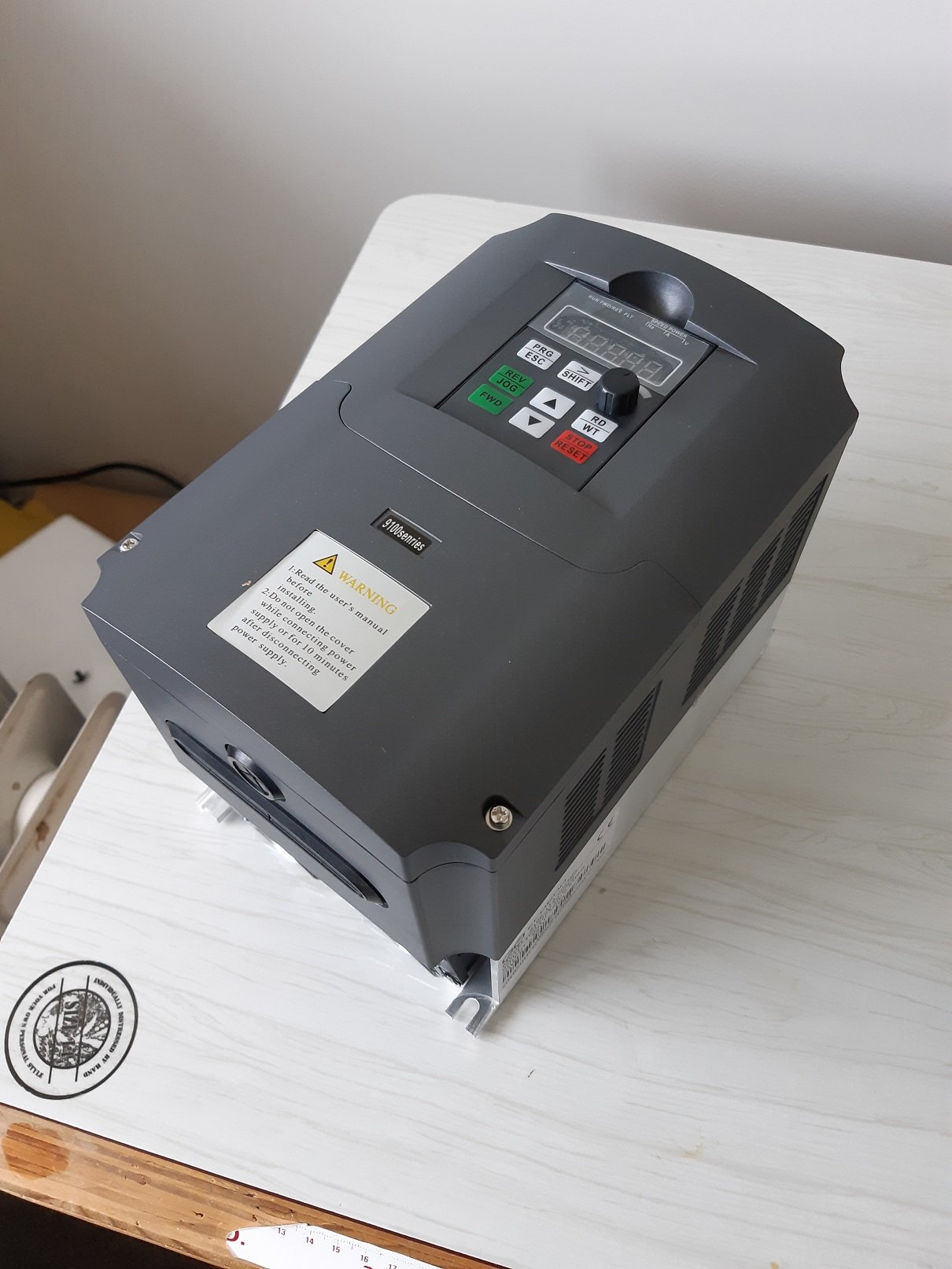
Well, shit! It just turned up today!!! 50 days since "leaving" china airport. The last tracking update was June 23rd.
Looks okay. I took the covers off and the circuit boards look well made.
"senries" mmm hmm yep, defo china spec.
I guess I will find out if I wasted my money when I try power up my 5.5kw motor. Hopefully I get around to that this weekend.
-
4
-
-
"
(i)ABS and Polycarbonate helmets shall not be painted, and(ii)Composite shell helmets may only be painted with a paint approved by the helmet manufacturer, and"
https://manual.motorsport.org.nz/index.php/knowledgebase/36-2-01a-schedule-a-1/
-
1
-
-
AFAIK, if it's for motorsports, a painted helmet will fail scrutineering.
I could be wrong... but you did say "opinions".
-
2
-
-
59 minutes ago, moparmuppet said:
Cheers @Adoom That plane must be getting low on fuel. If it runs out it will be stuck up there forever. If it turns up I would be keen on your review of it (Mauser lathe right?)
Just seen this on T.M. but it sure seems arse about face with the wiring. https://www.trademe.co.nz/Browse/Listing.aspx?id=2725788388 230 1 phase to the motor and converter out the other side? I just want a VFD with a PDL plug on the output I would think.
Do you have a link to the VFD you allegedly bought? Thanks for clearing some of the muddle up. Seems like if I am rated 230V Delta it shouldnt be too hard. (easier than getting a single phase and making it reverse. Gonna email the agents as well though. Nothing like doing it once, poorly eh?
Meuser.
"Mauser" is a... gun?
That mystery white box is probably just full of big capacitors. An oldschool way to run a 3ph motor on 1ph. I believe there are downsides to doing it that way. But that is the same trademe seller I mentioned that has the VFDs too.
This is what I ordered. The 7.5KW option. https://www.aliexpress.com/item/4000927690757.html?spm=a2g0s.9042311.0.0.48194c4dFSZbhp
Remember, I'm not an electrologist, this is just from the research I did before ordering my VFD.
-
1
-


Adoom's 1972 Triumph 2000
in Projects and Build Ups
Posted
Fuck I hope I don't ever need to remove this.