
- Popular Post


ProZac
-
Posts
1254 -
Joined
-
Last visited
Posts posted by ProZac
-
-
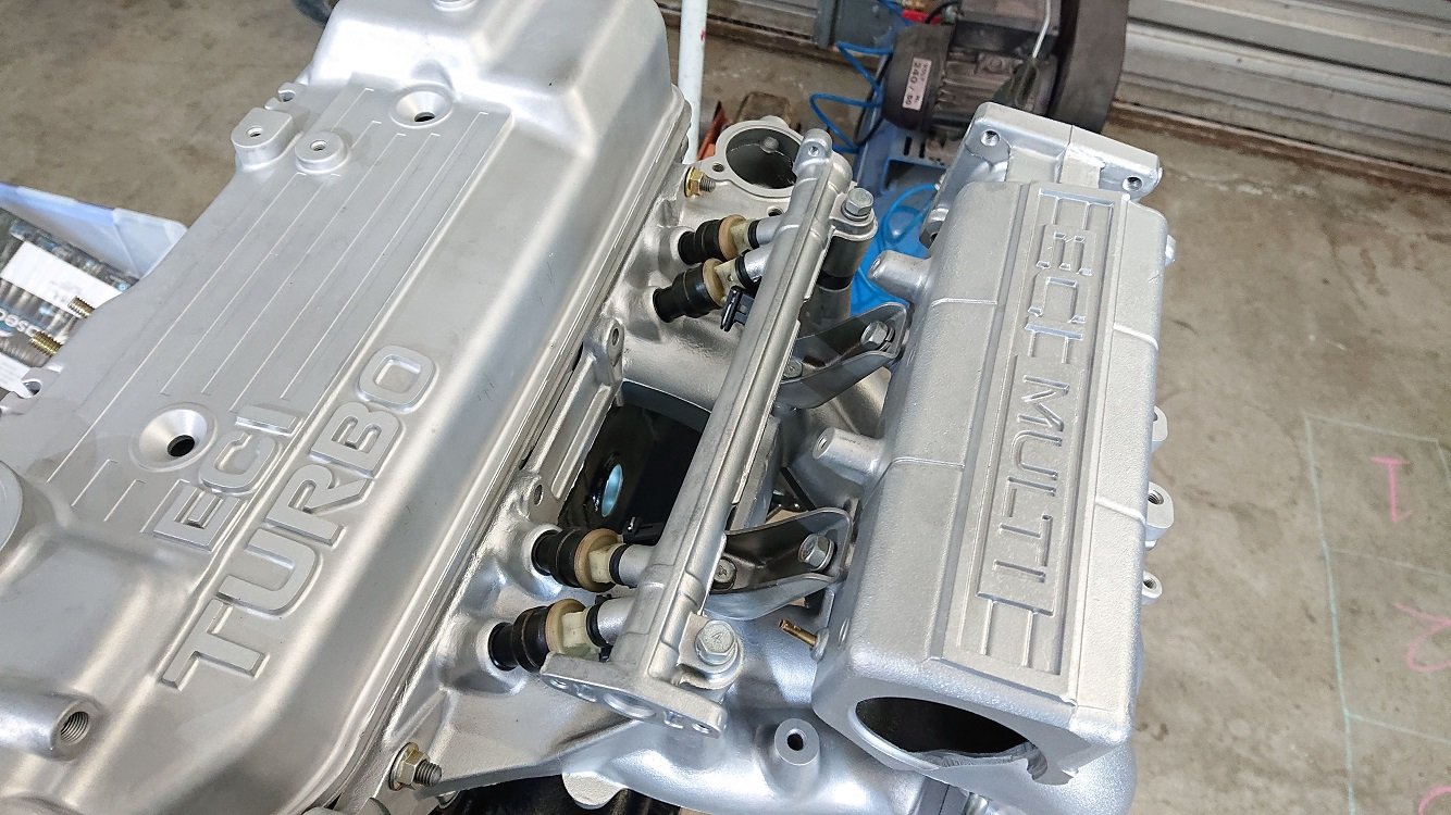
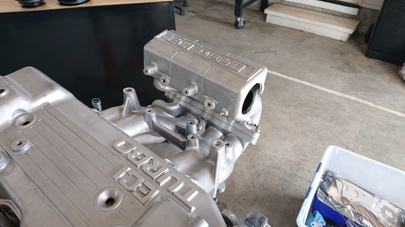
Have been working on this a bit in the holidays, getting the inlet manifold work done. I've thought a couple of times that I should have just bitten the bullet and made an inlet manifold from scratch, with the amount of work it is to get this one sorted properly for a RWD application... But I'm this far in, so I'll finish it off. Most obvious jobs are to swap the throttlebody onto the other end of the plenum, and reroute the coolant setup.

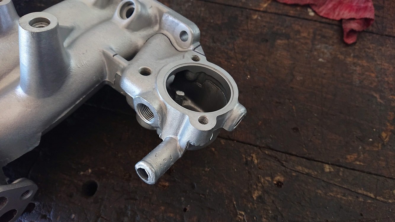
I've seen a few RWD setups with this manifold where the thermostat housing is left where it is and a hose is run to the front of the engine, but as this is a RWD head the waterjacket inlets in the head are setup for the coolant to flow out of the front of the head. Leaving it like it is, with it at the back, risks a hot-spot in the front of the head. The factory Starion setup has the radiator bypass from beneath the thermostat (which is at the front of the head) pass through the inlet manifold to keep it warm. This helps with the fuel film problem TBI setups suffer from as you've got so much area for the fuel to pool onto. As I'm all about the port injection now, I don't need that, but there still needs to be a radiator bypass, so I'll run that from beneath the thermostat housing (which I'll need to make) down the middle of the inlet manifold to the factory return pipe that runs along the back and side of the block into the waterpump. This factory pipe also has an inlet on it for the coolant return from the heater core.
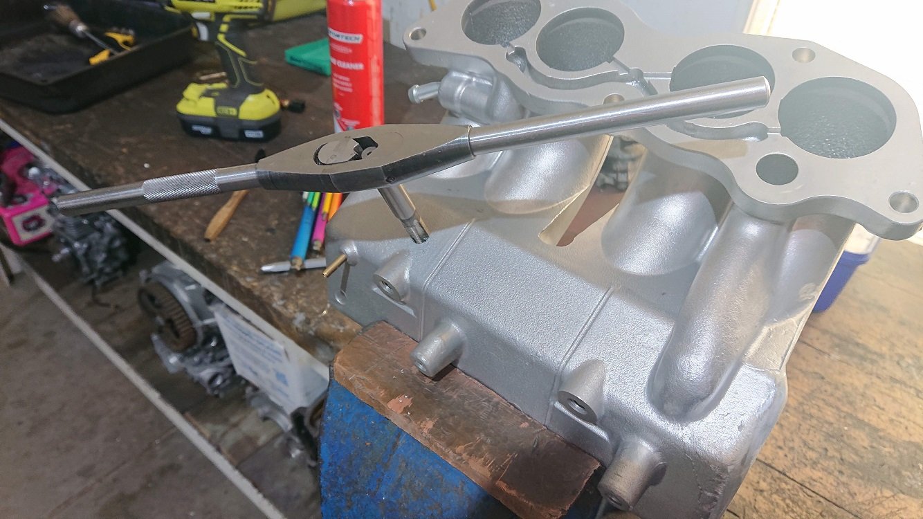
Lots of hacksawing, angle grinding, flap wheeling and powerfiling later it's looking pretty tidy back there. I'll need to weld a block on there which has a port to supply the heater core, but that'd the only fitting I should need there. I might put the ECT sensor there too, as it'll be out of the way.
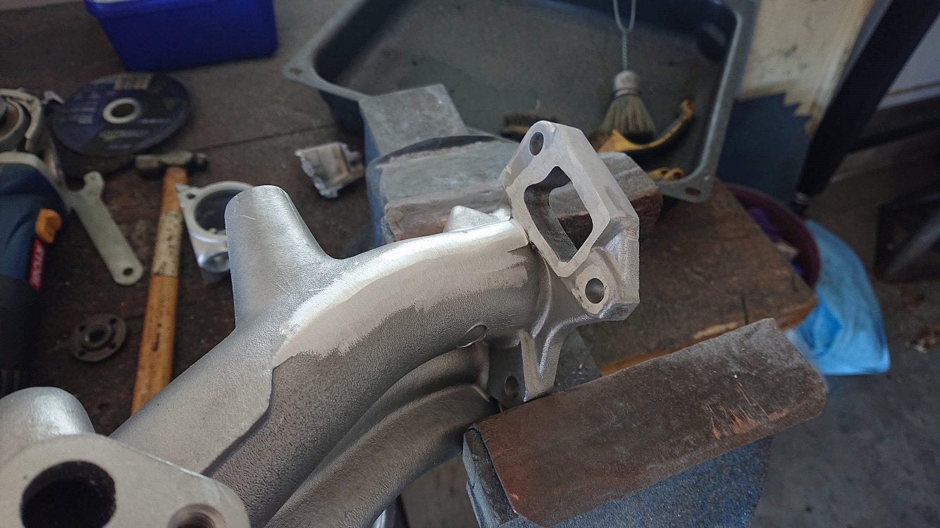
Hacked off the throttlebody flange and tidied it all up to make a plate to weld in place to seal it off.
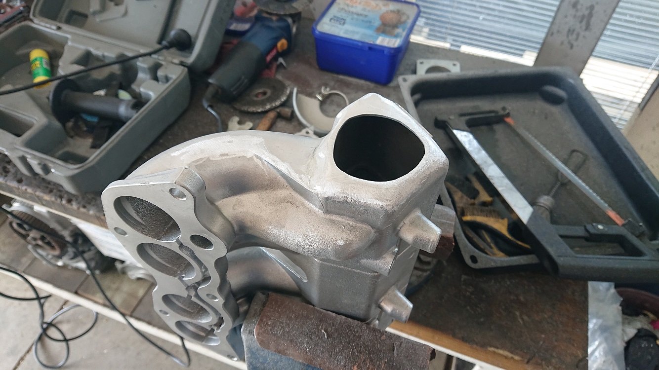
While I had all the power tools out and was making a mess anyway, I hack off all the little backets and bits and pieces I wont be using. Heaps more power filing later and it's all cleaned up.
Found a good spot underneath where there is about 10mm of wall thickness to drill and tap to 1/8NPT for the IAT sensor. Sensor is a delphi unit with a DTM 2-pin connector. Has a brass body where it seals to the plenum, but a plastic housing after that with an exposed tip. Should be nice and fast reacting for the temp swings turbo's produce, and not suffer too badly from heat-soak (I hope!).
Should be pretty out of the way down there. That space is going to be quite tightly packed though, with the radiator bypass tube, and the outlet from the fuel rail back to the pressure regulator running through there also. Plus, the wiring harness. It'll have quite a bit going on in this space. 4 injectors, 4 coils, ECT, IAT, MAP, EFP , Crank + Cam triggers and Ethrottle all within that area. Will be a fun harness to build :-). The injectors (also ones I've had for years) are EVO VII 560cc's. They've had single spray pintle caps put on them to work better with an 8V setup, and so I can orient them like in the picture with the plugs heading underneath, instead of directly on top. The reason for this is because of where I'm going to mount the coils.
Pretty simple 3mm aluminium sheet metal backet picking up of existing mounting holes. Will get it profile cut and bend it up at work. Has mounting for the MAP sensor underneath also. Coils are knockoff GM581's, which I've not used before, but should hopefully be up to the task. I could only buy a pack of 8 of them, so I've got 4 spares, hah.
It's bloody humid today, so we're off to the beach for some FnC for dinner and a bit of a swim.
-
 8
8
-
-
Nah mate, Black one I'll have forever I think. Can't explain it, but have a good connection with that car. I've been collecting parts still, and I've got pretty much everything I'll need to do a really nice GSR-V replica. 12V DASH head, all the big driveline, later model interior... Should be good :-).
-
1
-
-
46V should be the right code. It's the colour we went with for the racecar at Uni this year, it looks unreal.
Dooooo iiiiit.
-
8
-
-
Lol Valiant.. I may sometimes push the speed a little when I'm on the way home from work.... ;-).
d.p.n.s - I miss it sometimes too. Well, the access to parts anyway, hah. No, I still have my black Starion, its sitting, waiting for some attention. 2020 might be the year? :-).
-
1
-
-
- Popular Post
- Popular Post
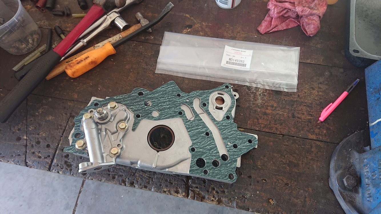
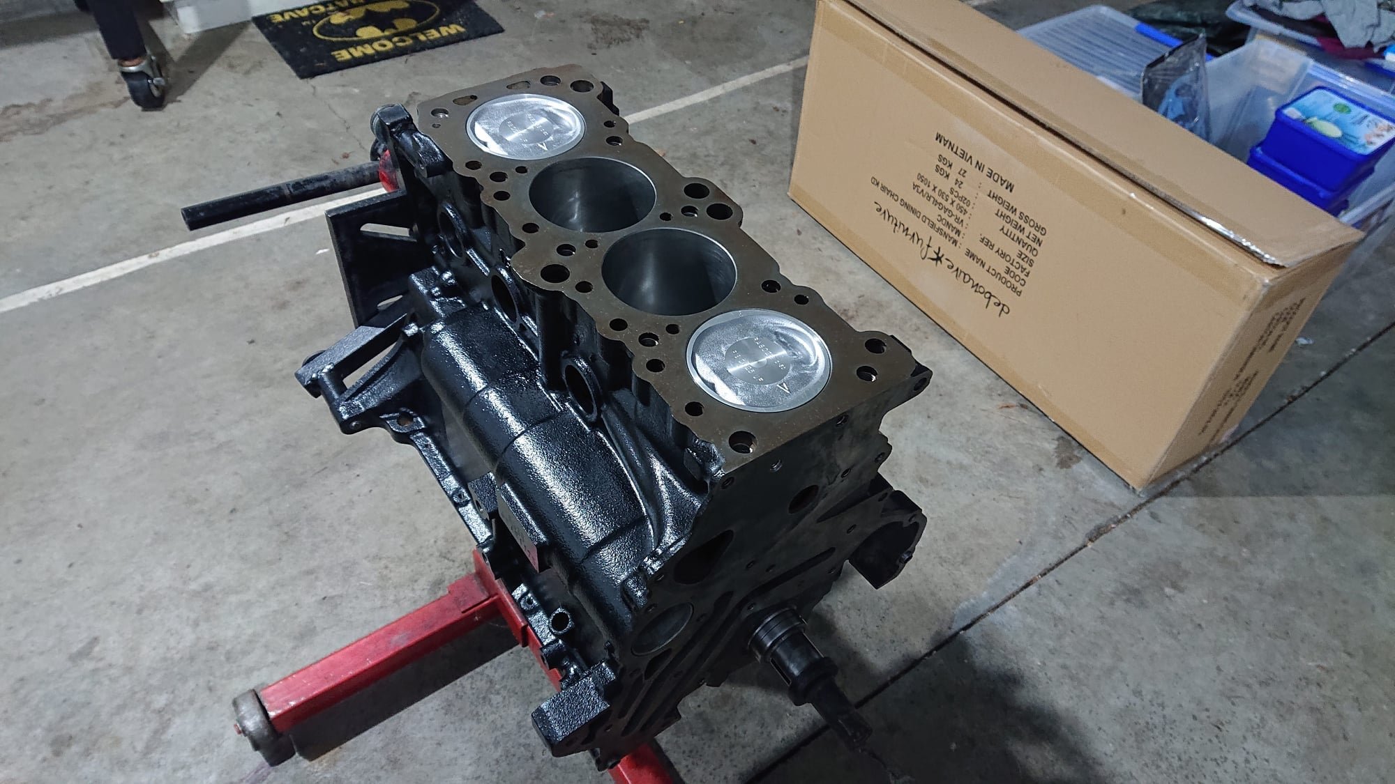
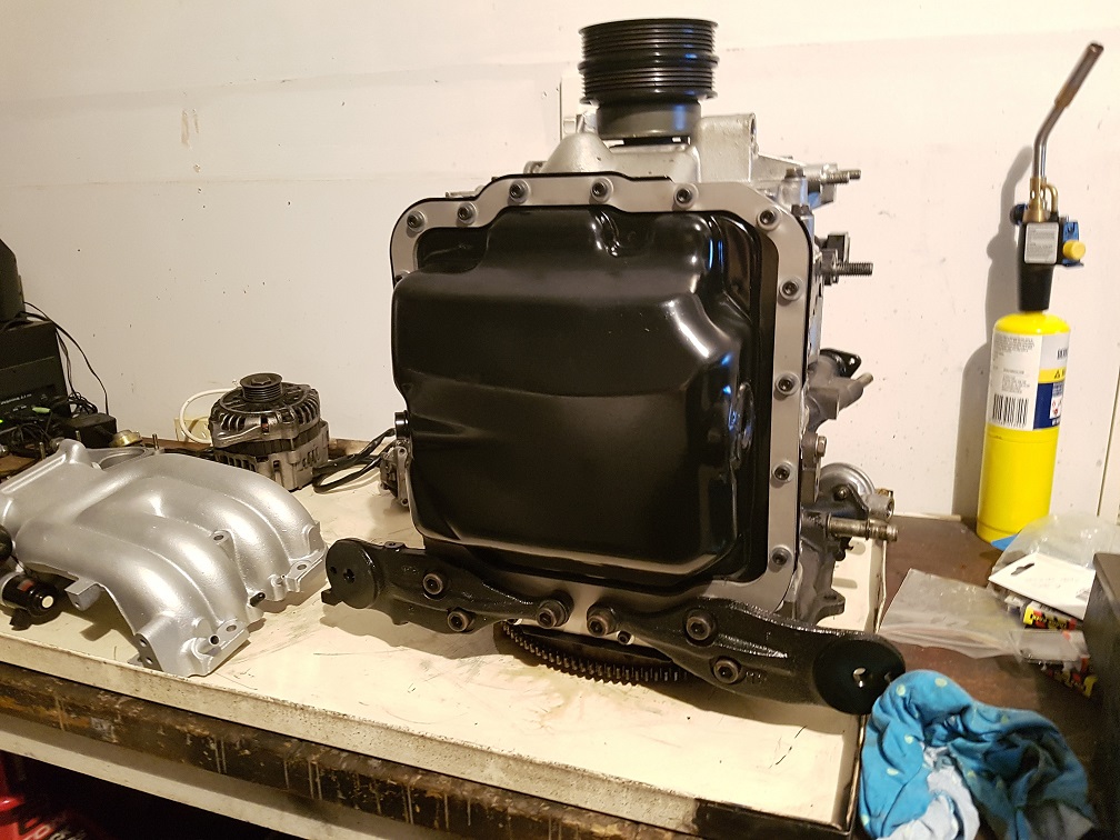
I like the prices and ease of use Amayama provides, but bloody hell the shipping takes forever! My oil pump gasket finally arrived today though (ordered a month and a half ago), which let me assemble the rest of the short block finally
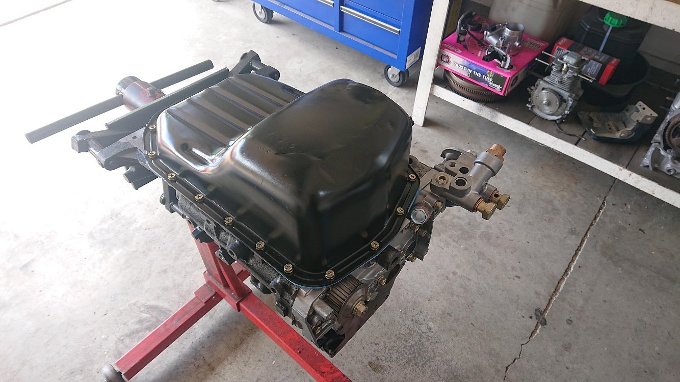
The part number on this gasket has been superceded a couple of times over the life span of the 4G63 SOHC, but this is apparently the replacement for all earlier versions, and is the gasket for a 6 bolt DOHC motor. Everything seems to line up, so I'm sure its fine. Once that was torqued up I could install the oil pick and get the bottom end buttoned up. Sump has had a few hits in the front of it, but still serviceable. I gave it a quick blast and paint a couple of months back. I find CRC Black Zinc works really well for stuff like this, but you need to give it at least a month to properly harden up before handling.
Had a bit of time up my sleeve, so did a bit of a dry-fit of the rest of the pieces to see what I need to finish off. Routing for the crank sensor wiring will work out okay. I'll make a couple of brackets and cabletie it in a couple of places to keep it out of harms way. It can exit up by the head, as there is an opening there as clearance for the distributor. Speaking of distributors, I've got one on the way to me to cut up and hopefully turn into a cam trigger. I've looked at mounting something behind the cam wheel, but there are no easy mounting points there. I could weld a boss to the head, but if I can make it work tidily with a chopped up dizzy, it's an easier solution.
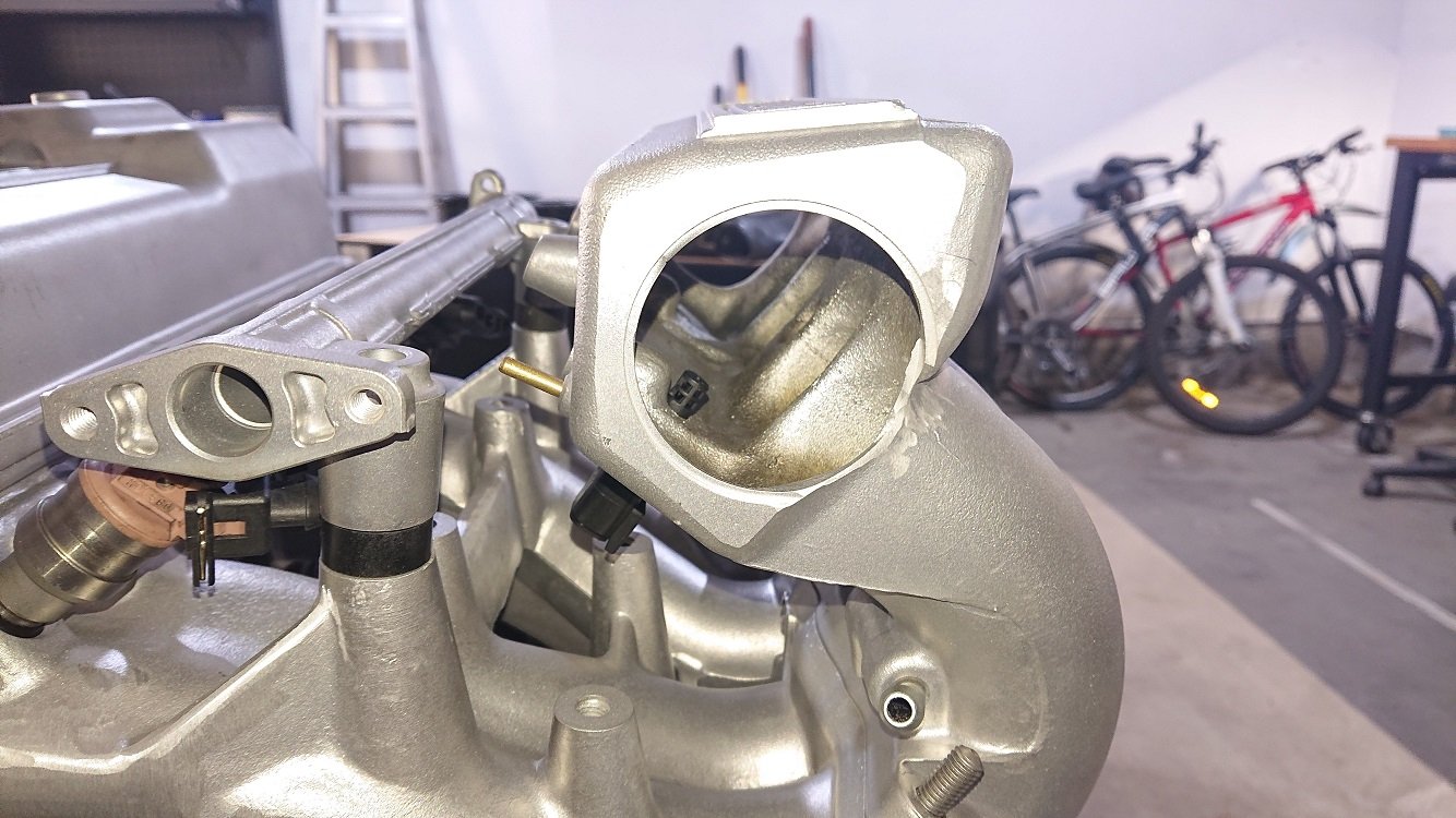
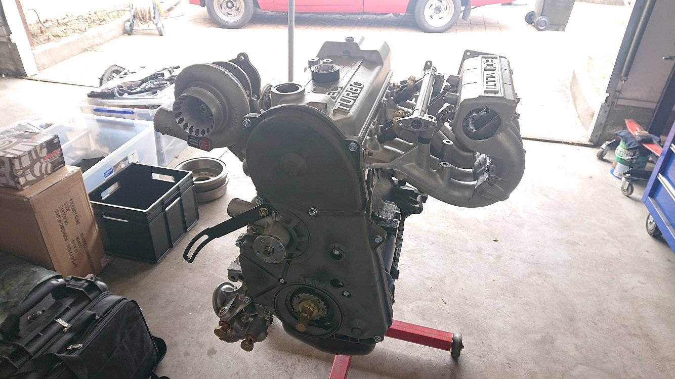
Finally offering up the turbo to the head was a pretty good moment, I like the way it looks, because I like 80's excess :-). Its an EVOIII big 16G, but with a larger compressor cover. Looks like a much 'bigger' turbo than it is ;-).
Next up I think I'll tackle the mods to the inlet manifold. Need to make up a flange for the throttlebody and weld it on the front. Trim off all the crap at the rear and weld that closed. I'll also cut off the original thermostat area, and make a piece to weld on to give fitting locations for the heater and bypass hoses. I want to move the thermostat housing to the front of the head though to keep the flow through the head the same as originally intended. Will give the manifold a quick scan too, as I want to pick up on some bolt hole locations to make a sheetmetal mount for a set of LS2 coils. They're just cheap aliexpress knockoff ones, but I've heard good reviews... Will see how they go :-).
Happy holidays all!
-
18
-
 1
1
-
- Popular Post
- Popular Post
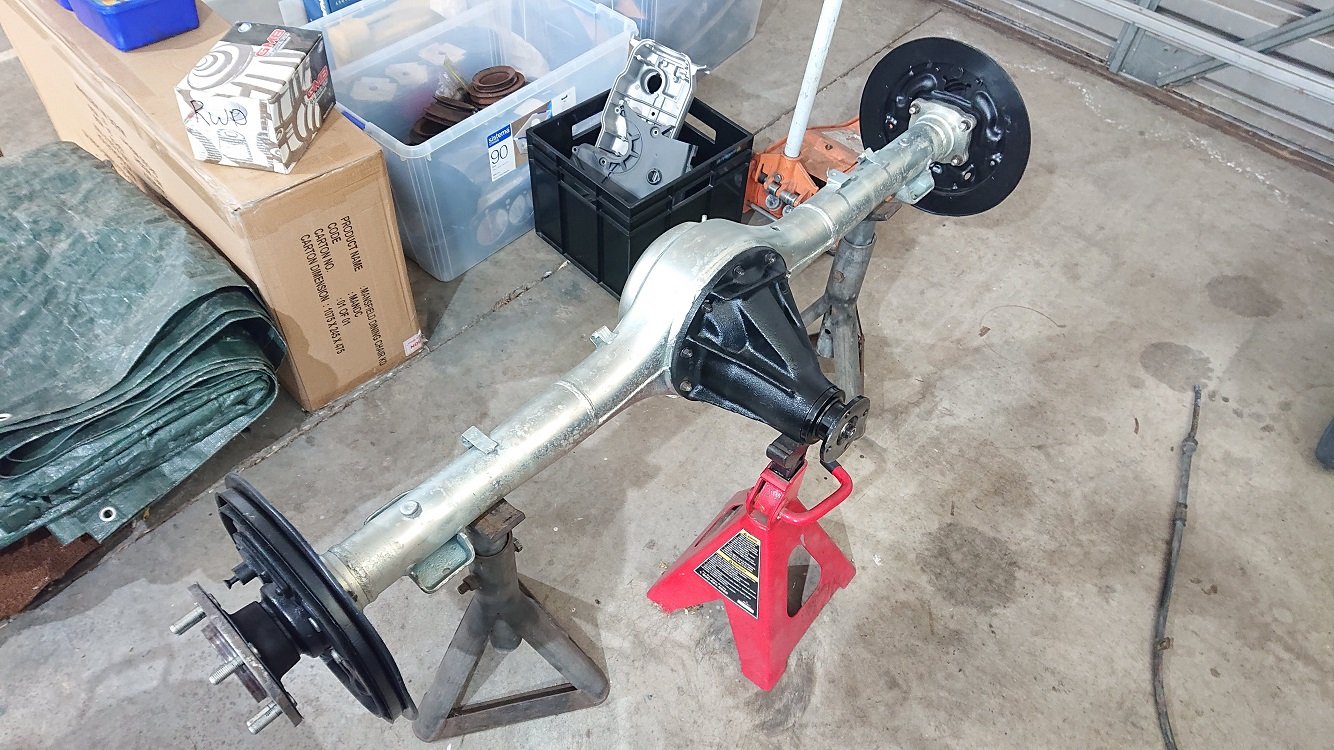
The wife and Child were away this weekend just been, so it was a good opportunity to get the rear axle swapped in my truck.
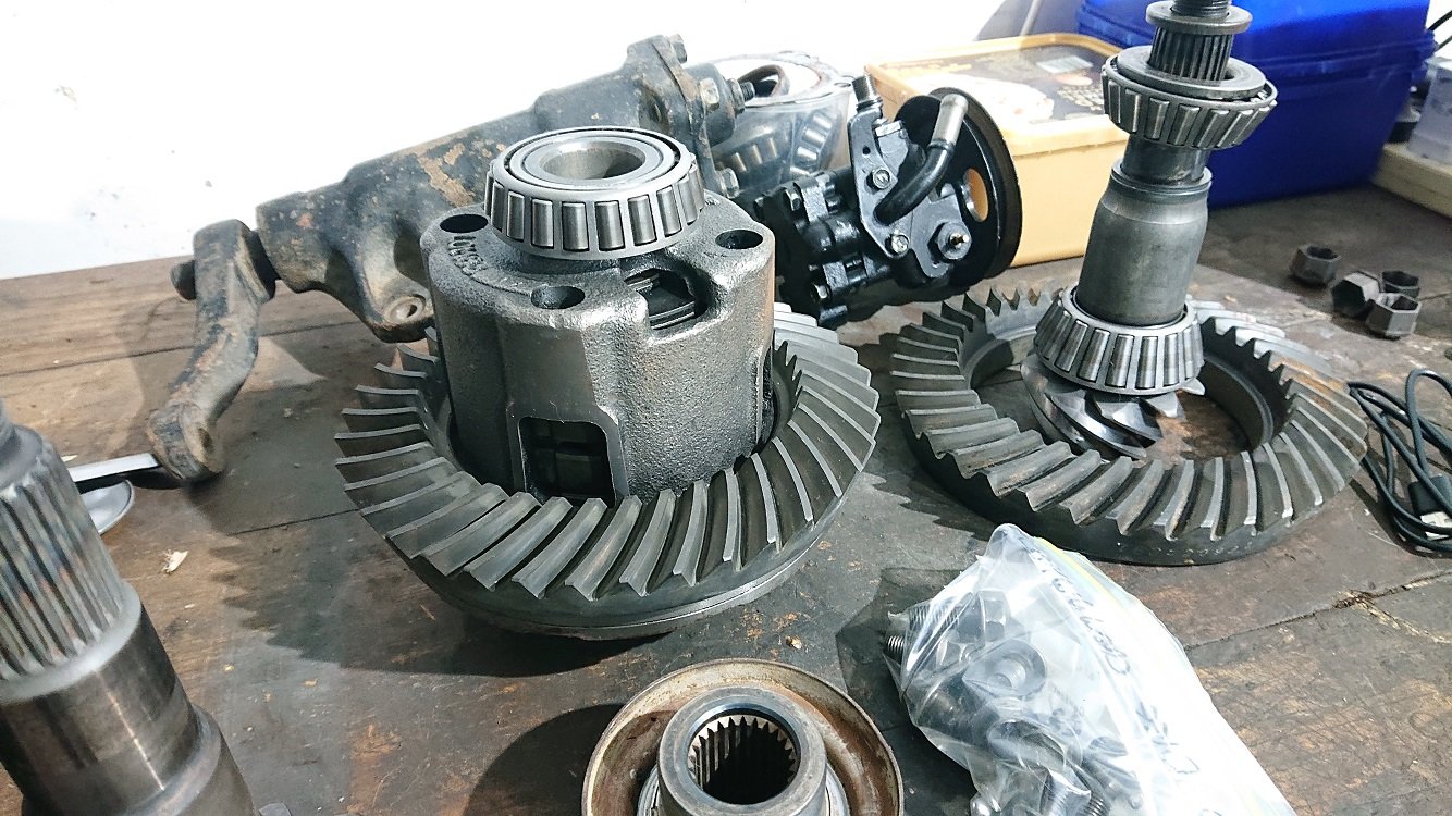
I had The Diff Shop in ChCh do the assembly of the diff for me, as they've got stocks of shims to get things in spec, and I didn't really want to muck around grinding things. It's a mitsy LSD center from a 2nd gen L200, modified to give another friction surface inside, with a heavier belleville spring installed to give some more pre-load. Should lock up a little harder and just be a bit tighter all around. The gears are 3.54's from a late Starion over in the states, hoping to get the 100kmph cruising RPM down a little.
The housing was dipped and zinc plated. I probably should have painted it black before putting it in, but a little bit of bling never hurt :-). Swapping it over was straight forward, only hiccup was getting the brakes sorted. I hate drum brakes, but they're more than adequate for the usage this things sees. Pretty much everything in there was new around 10,000 k's ago, so its all still in good nick. Had to loosen off the handbrake cable adjuster all the way to get it together.
I've adjusted it back up, but it needs a few more turns I think, tried locking up the rears from 50kmph in the dry lastnight and it was a no go. They locked up in the rain this morning though, so it's close. I can also confirm that the LSD works as expected :-).
-
15
-
- Popular Post
- Popular Post
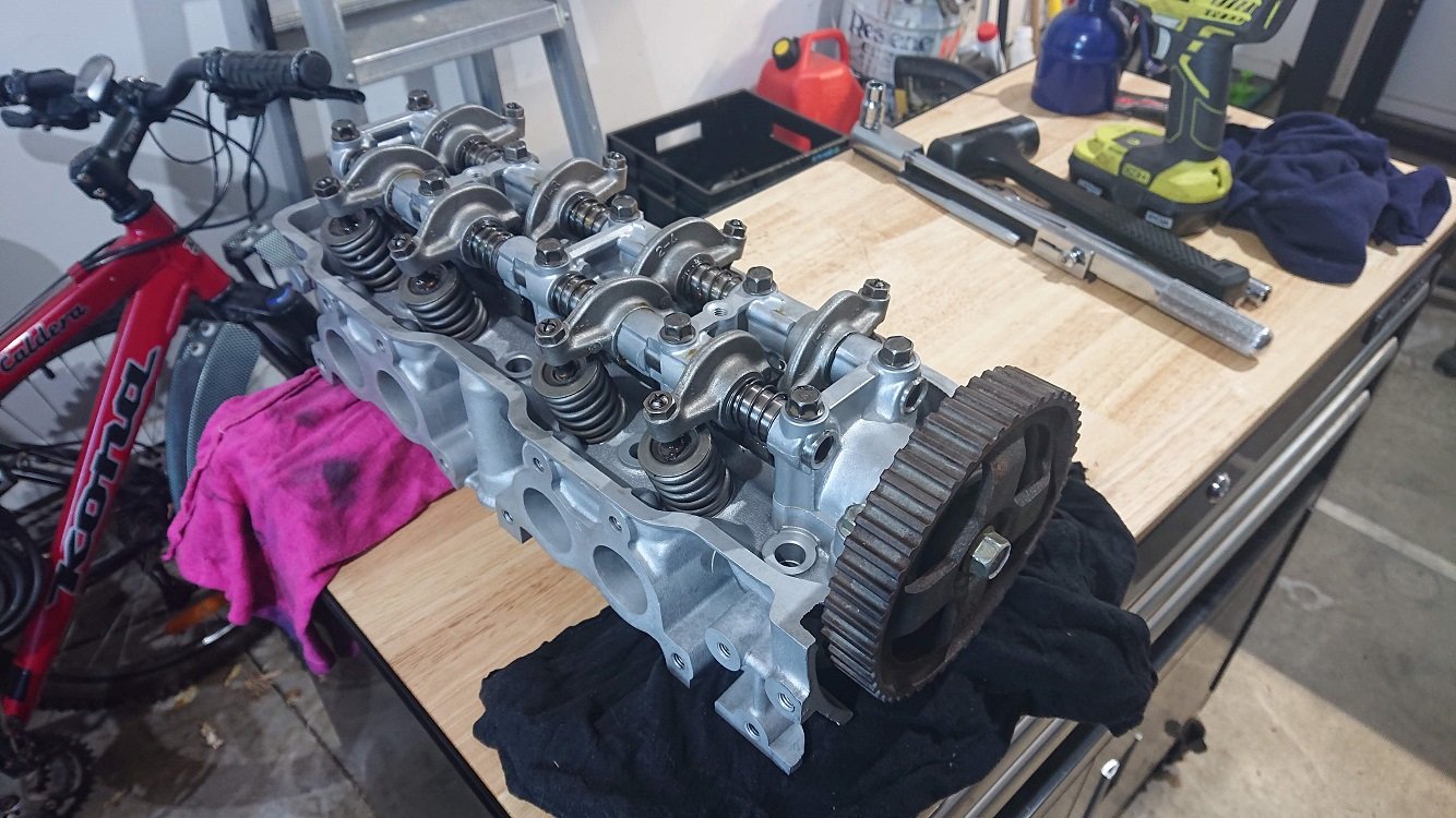
Years and years ago I made up a little bracket to go on the end of a home-made clamp, for valve collet removal / installation. It was a case of 'I'll buy a proper one, one day...'. However, this thing still persists, and still does the job :-).
A bit more mucking around trying to remember how this goes back together and which way around things go, and its all sorted. Just need to torque up the cam bolt and it's ready to pop on the motor. Have set all the valve lash really roughly, hopefully it'll sit in the right position to get the cam belt on, otherwise I'll loosen all the rockers off again, get it timed right and then re-set. They'll need to be re-set hot anyway.
As mentioned the cam was ground at Kelfords, pretty standard specs, should pep it up a bit
Waiting on some parts from Amayama, an oil pump gasket and the head dowels being the bits really needed to pop the rest of the motor together. Its great being able to get good prices on factory parts, but the shipping time is pretty extreme. Oh well, no rush eh? The engine has been sitting under the bench for years as it is.
-
15
-
Legit tiny.
It's far from mint, but mint from afar ;-).
-
2
-
-
Hah, yes, I do. How do you like the progress on my fence? I'm at 4 years so far, and its still not finished ;-).
-
1
-
-
HMU with your shit Mitsy chat :-).
-
1
-
-
- Popular Post
- Popular Post
The cylinder head for this thing is a later 8V one from a Euro Spec Starion. It's a good one because it doesn't have any jet valves which usually lead to cracking issues. I've done some simple port work to this one, just de-shrouded things and decreased the short side radius on the intake port, and smoothed things out. When I did this I didn't have any access to flow-bench gear, so its just common sense stuff with no measurement to back it up. I took it to Kelfords, and they tidied it up further for me, and ground the cam to 272/272 @ 0.1mm (230/230 @ 1mm), 10.5mm net valve lift. Should get me enough air flow for the power I want to make, where I want to make it :-).
Another historic Repco purchase was a set of new valves. The original ones could probably have been cleaned up, but these were on clearance, so only a few bucks a valve at the time. They've all lapped in really nicely. I vapor blasted the head at work (its a new piece of gear we've just got, and I had to commission it
), so it's really clean. Currently with a local engine machinist getting a quick skim. Then I can assemble it and get the long block finished.
-
20
-
- Popular Post
- Popular Post
The motor for this thing is a case of using up parts I've had under the bench for many years. Before, and while I was at Uni I was a register biscuit at Repco, and took the opportunity to stock up on bits I knew I'd need one day. Even finding a lot of this stuff can be hard these days, let alone the high price so much of it seems to now command!
The block is a really early Starion one, so is stamped G63B and is wideblock. It also has no oil feed for the rear bearing of the upper (RH) balance shaft. This is great, as I'm deleting these anyway for simplicity, so its an oil feed I don't need to block off. They early blocks were tapped M8x1.25 for the timing tensioner stud and clamp bolt. The stud, bolt and tensioner I have are for a later block, so I've drilled and tapped these positions out to m10x1.25.
One of the bits I grabbed before leaving Repco was the last set of 4MKRY-8028(050) pistons they had in stock. Moly top ring, 0.5mm oversize and a later model ring design that is a little smaller, giving the pistons stronger ring-lands. They have a 12.3mm bowl, which should land me at around 8.5:1 static compression. Still pretty low, but good for a daily. Better than the stock 7.6:1 the motor originally had! I had MPL in ChCh machine the block for me (also many years ago!), and we went for 0.05mm piston to wall. Its larger than the factory spec for SOHC gear, but on point with the later DOHC turbo specs, and I should be seeing similar amounts of heat.
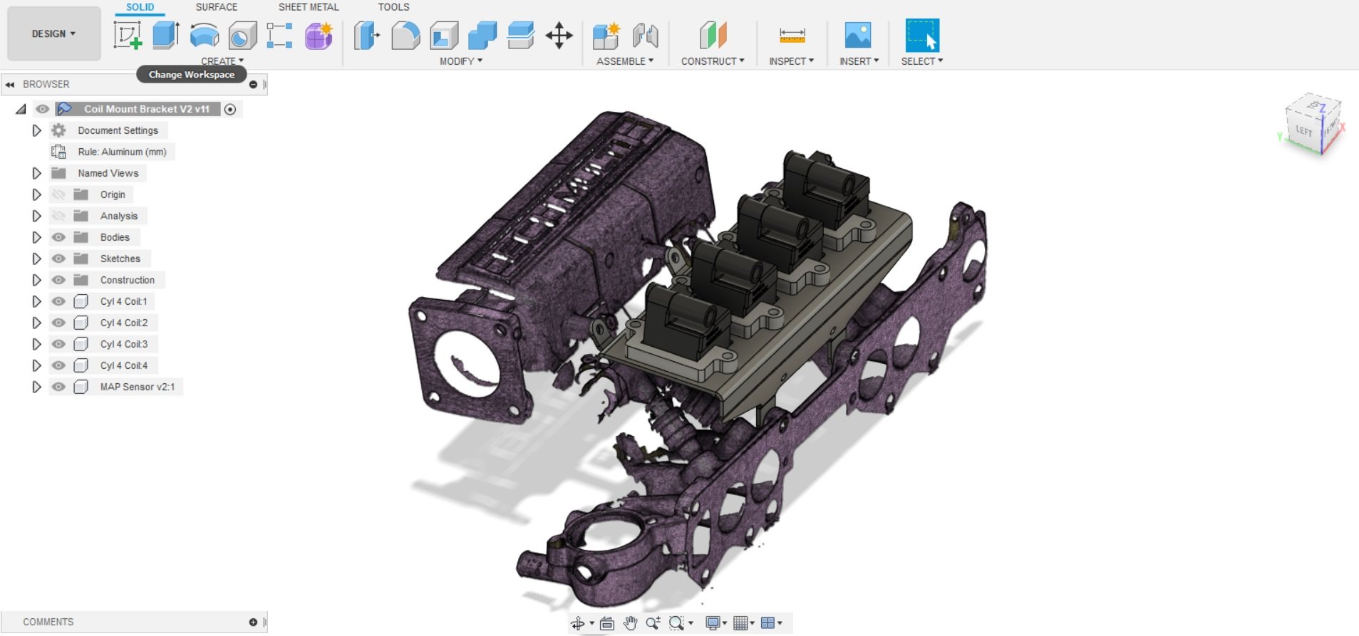
I'll be running fuel injection and coil per plug on this motor, with a Link ECU, so I need to get good engine position information to the ECU. I don't have any distributors for these motor knocking around any more, and I don't like the look of them hanging out the side of the head, only being used for engine position information. Plus, IMO crank position information should be directly measured at the crank, not from a cam driven element via a timing belt that whips around.
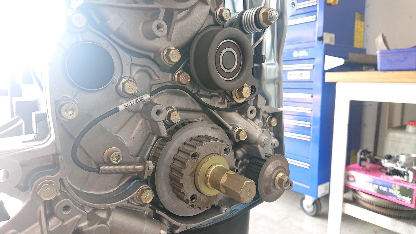
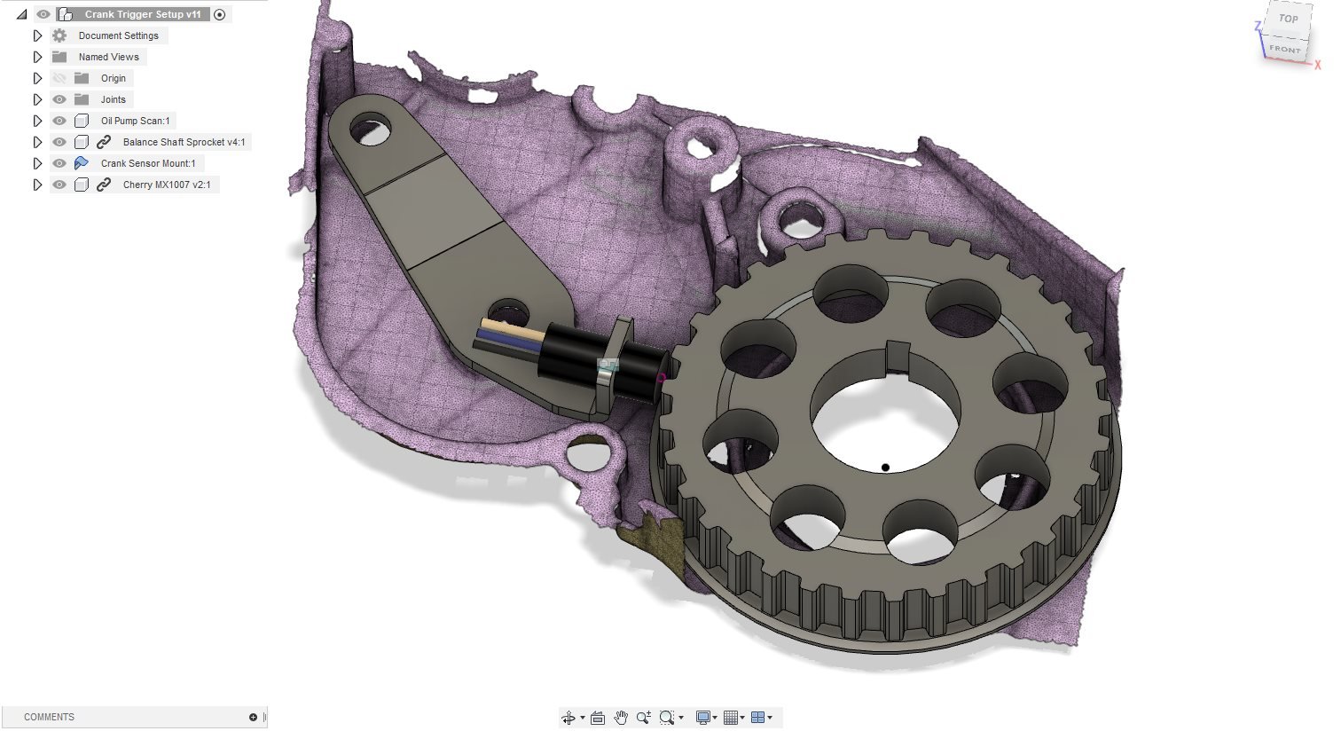
Although I've deleted the balance shafts, the crank sprocket for the belt is still there as it's also a spacer for the timing belt sprocket. You can remove this and replace it with just a spacer, but it looked like a good spot to take some crank speed information from. I had a couple of gear tooth sensors (Cherry GS1005/7) rattling around in a drawer, and as this isn't a missing tooth measurement, they should work well for this application. They don't work well in missing tooth scenarios because the tooth that ends the gap causes a much larger change in magnetic flux density (which is what the sensor is really measuring), and it stuffs the automatic calibration the sensors have built into their ASIC's. I was chasing this problem for a solid week on a a race motor I was tuning, it sucked to find! I did a temp setup with some blutack and it gave a good signal on the scope, so I went ahead with it
We've got some great 3d scanning gear at work, so I took a quick capture of a relevant section of the front timing case / oil pump. A bit of noodling and modelling I came up with a simple sheet metal bracket, made out of 3mm steel. The Cherry sensor had too large of a diameter to get it in the right place, but I found a honeywell sensor with a 3/8-24 thread which has a decent temp and vibration rating and seems to work well. Scope measurements when spinning the sprocket by hand (the crank key is removed) show a nice square pattern, will see how it goes when the engine is actually running!
Kiggly racing do a very similar setup, but it's around $400, and I don't really want to part with that ;-).
The short block is pretty much assembled, just waiting on the timing cover / oil pump gasket to arrive from amayama. Finding all the right fasteners I had done a very average job of bagging up also took quite a while! I've done a full dry assembly now though, and I should have everything.
-
15
-
- Popular Post
- Popular Post
As this is my daily, I'm structuring the modifications to have as little off-road time as possible. This usually means buying the parts I need, doing the modifications, swapping them in, then then on-selling the factory gear. A good example of this is the rear axle.
As this is a 'Sport' model with the 2l motor, it has the larger 8" crownwheel diff (often called the mitsy 'big' diff). This is great, as they're really strong, far stronger than I require, but it is also pretty easy to get other gear sets for them. Starions (another long-running vice of mine) also came with the big diff (5 stud models, anyway), and although they're IRS, the gear sets are interchangable (the centers also fit, but most IRS big diff stuff is 25 spline, whereas the solid axle stuff is 28 spline, late widebody starions being the exception to this and also having 28 spline axles).
I picked up an '85 l200 diff on trademe a while back, and took it all apart. I found a LOM83 LSD center from a 2nd gen l200 diff, and got some 3.54:1 gears from a late widebody Starion from the states. This all goes together pretty easily, I had 'The Diff Shop' here in ChCh do the final fit for me, as they have the shims and gear to get it all in spec far easier than doing it myself. No crush tubes in these things. It's got all new bearings and seals, so it should be a good unit. I had the axle casing stripped and zinc plated, as it has been sitting up on end in my garden for a year of so and was full of water, and rust.
Just at the point of putting the brakes together. I've got all new gear (springs, cylinder, shoes, drums, etc) for it, so it should last a while. Because I've still got the other diff under the rear of my truck I've got a reference of how it goes together too. Bloody drum setups!
The original 3.9:1 gears will find their way into a Starion diff I have, but that's a future project.
-
11
-
- Popular Post
- Popular Post

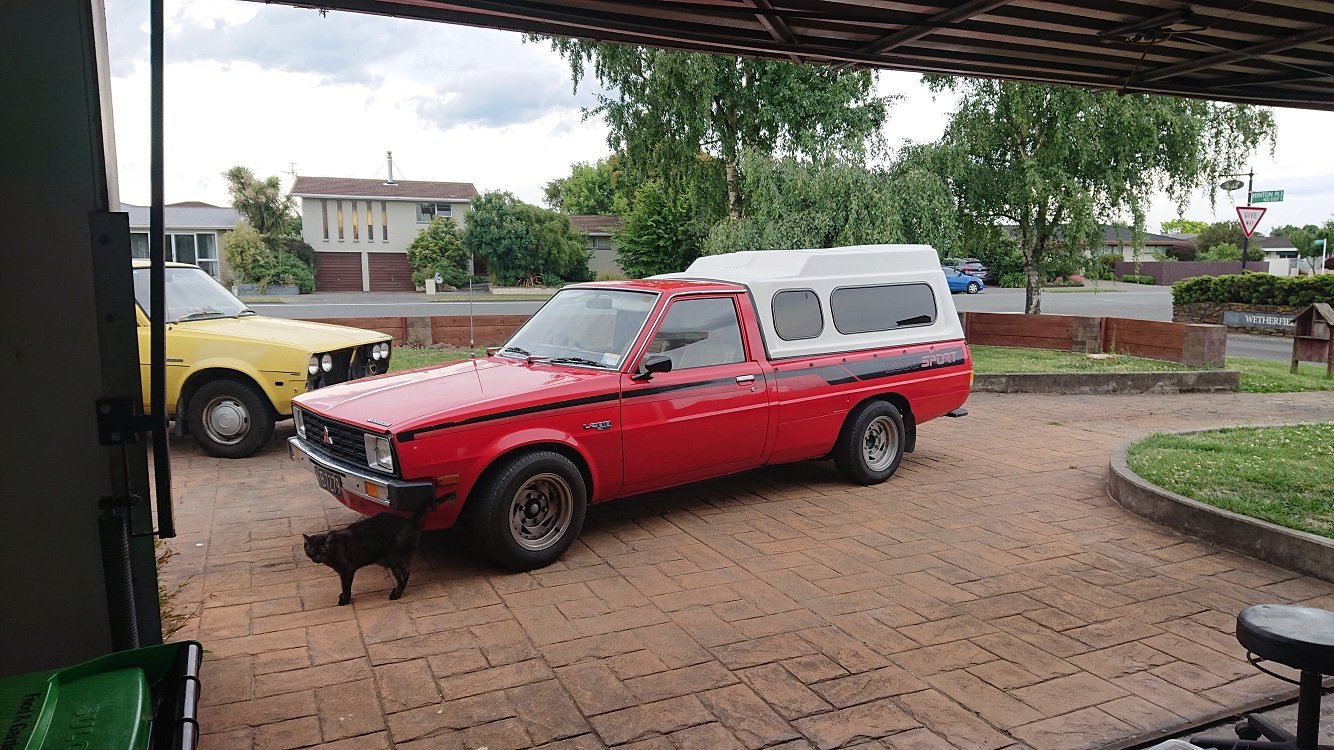
This ute has been a constant fixture in my life for many years now, and its pretty easily my favorite vehicle I've ever owned. It's never let me down, when something does break its so simple you can fix it on the side of the road, and it just gives you 'feel good' vibes when you drive it :-). I bought it from the original owners year ago, and it had never been more than 20k's from Sheffield (where it was sold new) in its life.
It's in good nick for one of these, with no major rust issues to speak of. The cab corners are all good, and the wellside is also rust free and pretty much dent free inside too. The canopy has never been off it, and the tray has always had a ply-wood spoil board in place. The interior shows its age though, with dash cracks and worn out bench seat.
I've done a bit of work to it over the years. Did a major overhaul of all the suspension and brakes a couple of years ago. Everything under there is brand new or rebuilt. 2" blocks in the back, 2" drop spindles in the front with 2nd gen vented brakes. 1/2 a coil off the front to get it sitting even. Everything poly-bushed, wheels are $50 cheapies from trademe I tidied up. They're probably due another tidy up by now, but I think i'll be changing them out for something else (wider) in the near future.
For the first years of owning the truck it was just a weekend vehicle, used for taking the garden waste to the refuse station, helping people move things around, etc. I had euro-diesels as I was commuting big k's each week for work... However at the beginning of 2019 I scored a fantastic job in Christchurch, so I no longer have to spend 12.5 hours a week commuting to and from work. When you add that into your work hours each week, its just too much time being idled away. As of a few months ago the euro-diesels are sold and the truck is performing daily duties.
So, its time for the second round of major modifications:
- 4g63 SOHC 8V.
- TD05 Big 16G turbo (EVO III).
- Galant MPI injection.
- 2nd Gen 5 Speed gearbox (possibly with a Starion gearset, if the ratio's are better).
- 3.54:1 gears, with and LSD center.
- Starion seats fitted general interior update.
I'm hoping for a good 200 buff horses to the rear wheels. Truck weighs in at around 1250kg's, mostly at the front I assume, so it should make it pretty lively with an LSD and 195's. Should be able to get better economy too, with the 5 speed (currently its a 4 speed) and the taller gears, and better fuel system. Not for the first few months I'm sure, as I'll be deep in the loud pedal a lot I'd say, but after that I'm hoping things improve ;-).
-
20
-
1
-
Keen for details on what calipers you switched too on the front? I've put 2nd gen drop spindles in the front of mine, put the 2nd gen calipers and vented rotors on at the same time. Want to add some more power soon though and want an option in case the stuff I've got on there now isn't up to it...
-
- Popular Post
- Popular Post
Work still continues on this car, albeit in fits and starts. Things have gotten a bit jumbled, but I'll continue showing how the turbo project is turning (pun intended) out, to keep things sort of linear-ish in this thread...
I continued to focus on the compressor wheel side of the turbo's first, and cut a couple more test pieces to get the fit to the compressor wheel really dialed in. Finally, I committed to machining the actual compressor housings, and was pretty damn nervous about doing so. I made up a fixture to hold them, which consisted of a piece of 60mm aluminium barstock, with four tapped holes in the end, onto which a plate bolts with countersunk fasteners. This plate has the holes to mount the compressor cover. Everything is made with a bit of slack, as we don't have a 4-jaw available for the CNC lathe, so I got it centered buy just snugging up the bolts holding the compressor cover to the fixture, channeling my inner Abom and bumping it around till it was as dead-nuts true as I could get it. Then I cranked up the mounting fasteners to keep it in that position.
First cuts had a pretty decent butt-pucked factor, but it all worked out swimmingly :-).
I'm going to have to modify the inlet piping to the turbos too to port-match, but I'll do that in the mill, as it'll be much easier to fixture.
I've got around 0.35mm clearance radially between the compressor wheel and the cover, when assembled there isn't any rubbing between the two if you force the shaft one direction or the other, so I'm calling this side of the job good :-). I had to do a bit of noodling and measuring to spin up an adapter ring that pressed into the back of the compressor cover to allow the T25 CHRA to slot in and get the right spacing, but it wasn't too tricky and everything fits together with the original circlip.
On to the exhaust side! If I thought the butt-pucker factor was high before, these puppies are HEAVY! I used the came fixturing method as above, but made new plates to mount the turbine housings. Once again quite a bit of measuring and noodling was involved to get it to all fit together, have the T25 CHRA's centered and spaced axially correctly, but once I put everything into CAD it wasn't too hard to figure out.
I used the big-momma boring bar for these, as I needed quite a bit of stick out to have sure the tool turret cleared the housing mounting flange at full cut depth. To be honest, it didnt actually clear, but only by .05mm or so, just left a little witness mark ;-).
Got a little chatter right up the top, but everything fits beaut.
I left a little more clearance on the exhaust side, around 0.6mm radial clearance, as I figure things here get hot, so better to lose a little efficiency, but maintain integrity ;-).
So... Yeah. Turbo mission is getting there. The whole setup actually fits together now, but there are mods to be done to the oil lines, intake piping and water cooling. I need to fit them to the motor to size all this up though, so finishing it off completely will have to wait till later.
Cheers :-).
-
19
-
On 11/6/2017 at 22:23, Pelo. said:
Thanks Zac
How is progress with yours?
My estimates of available time during fatherhood were.... Optimistic.
It's at the bodyshop at the moment though. Because it had to many little dings all over if from the ceiling, it's getting a windows out respray.
-
2
-
-
Oh wow, that's a gorgeous car. Red, wit the stock wheels will forever be my favorite look on an FD RX7. Amazing car dude :-).
-
1
-
-
Real Men Smoke Eagers. ;-). It's got slicks on it now though, i think they are just display wheels those ones.
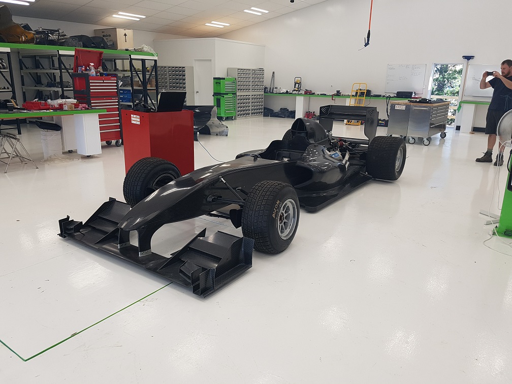
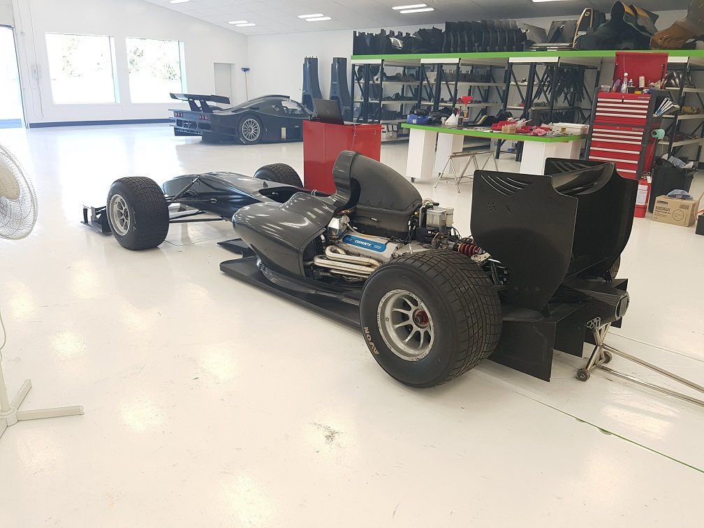
The bossman at work bought the defunct Lotus T125 project, lock, stock and smoking barrel. We built one up that's since gone over to Germany, this is the second built as the original T125's were. Its to be our testing and development car, for us to debug as many of the issues the T125's had as we can (flammability being the major one...).
-
- Popular Post
- Popular Post
Right, to get back to where I was lastnight before I was called away for Pizza and Wine (oh, gosh, what a chore my life is....)
Babies. Go have one. Now, honest, totes legit an awesome time :-). There are shit parts, but wow, overall its actually pretty awesome.
Work has been really busy, surprise surprise. I did _a lot_ of this:
In order to get the car we've just finished building going:
And go it does. The new track at work has been sealed, its got an (almost) straight that is about 1k long. Listening to this thing bang gears down there is pretty awesome. We've all been promised a drive, but I'll believe that when it actually happens.
Sooo, back to RX7 related things :-).
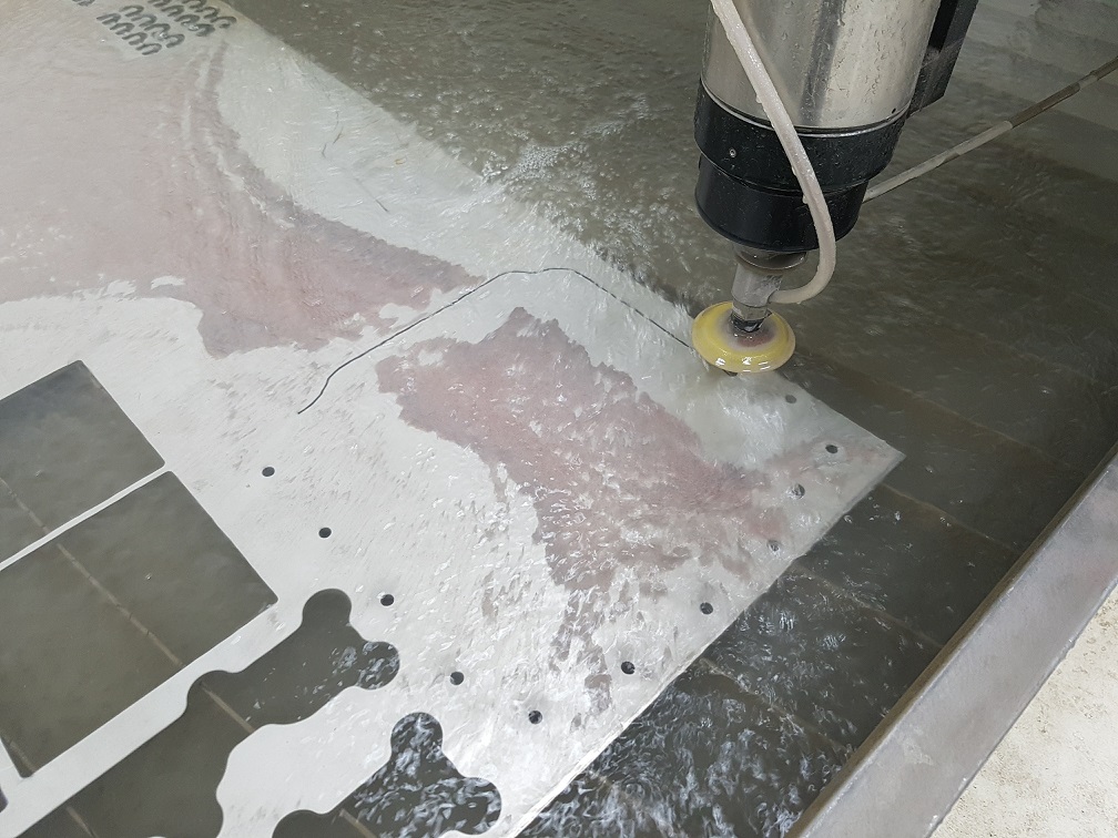
Because I'm an idiot and could just go the easy way, I gave making (instead of buying) a sump brace a go. Lots of tracing and scanning got me a cad model of what I wanted. I used a table cutter to cut out an outline of what I'd cad'd on paper, to see if I was on the right track. It all matched up to the gasket, so I committed and cut the profile out of 1/4" 316 stainless on the waterjet:
One of the first jobs I had when I got to work was to get the waterjet cutter sorted. Its a Chinese machine, with some terribly translated NCStudio software on the controller PC. With a bit of finesse though, I can hold a pretty decent tolerance on it, around 5 thou or so if I really try. This job didn't require such accuracy though, so I didn't replace the orifice or nozzle or anything, 0.25mm is close enough!
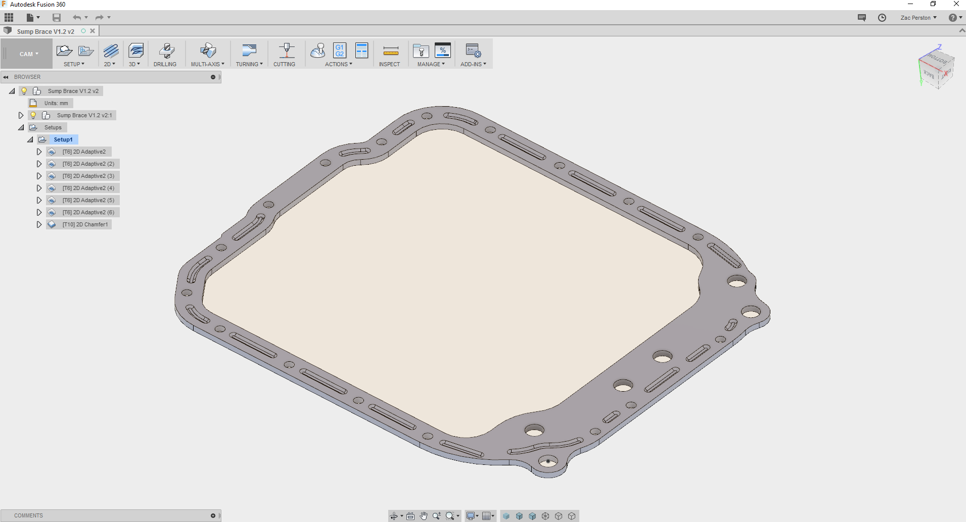
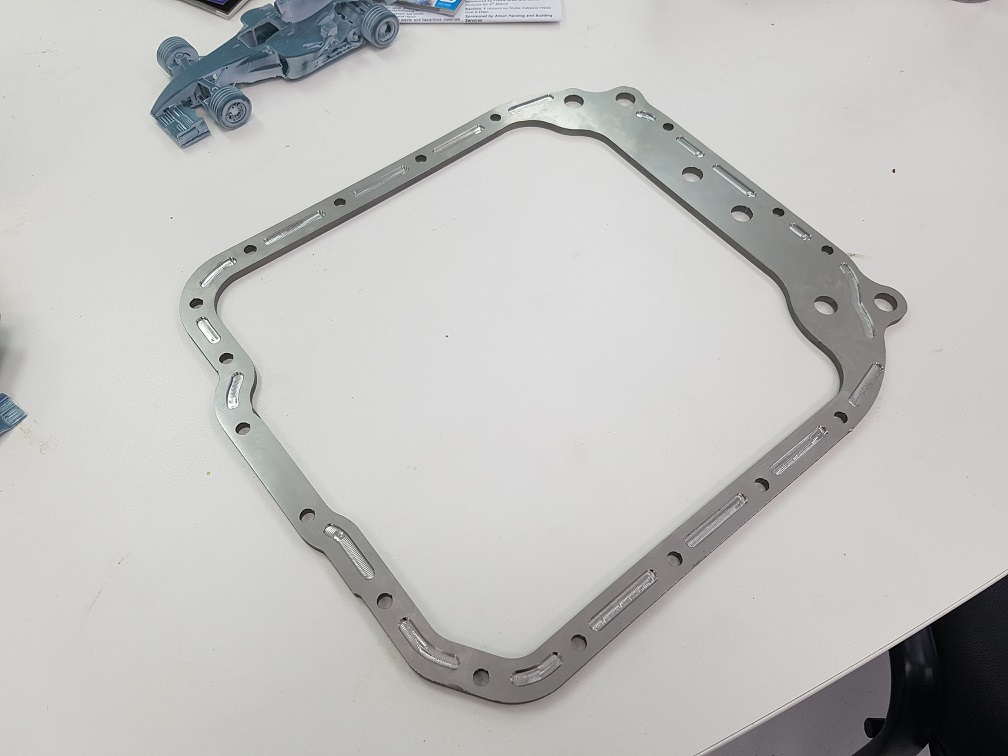
The profile cut out really nicely, and matched the gasket spot on. One thing that bugged me though, and seems to be the same on most of the commercially available sump braces, is that they don't have reliefs cut for the stiffening ridges pressed into the FD sump flange. As you bolt the brace up, it would just squash them flat into the block. With a bit of white paint to outline the ridges, and a few photos, I got the location of the ridges onto my model, and cam'd up some toolpaths for the CNC mill:
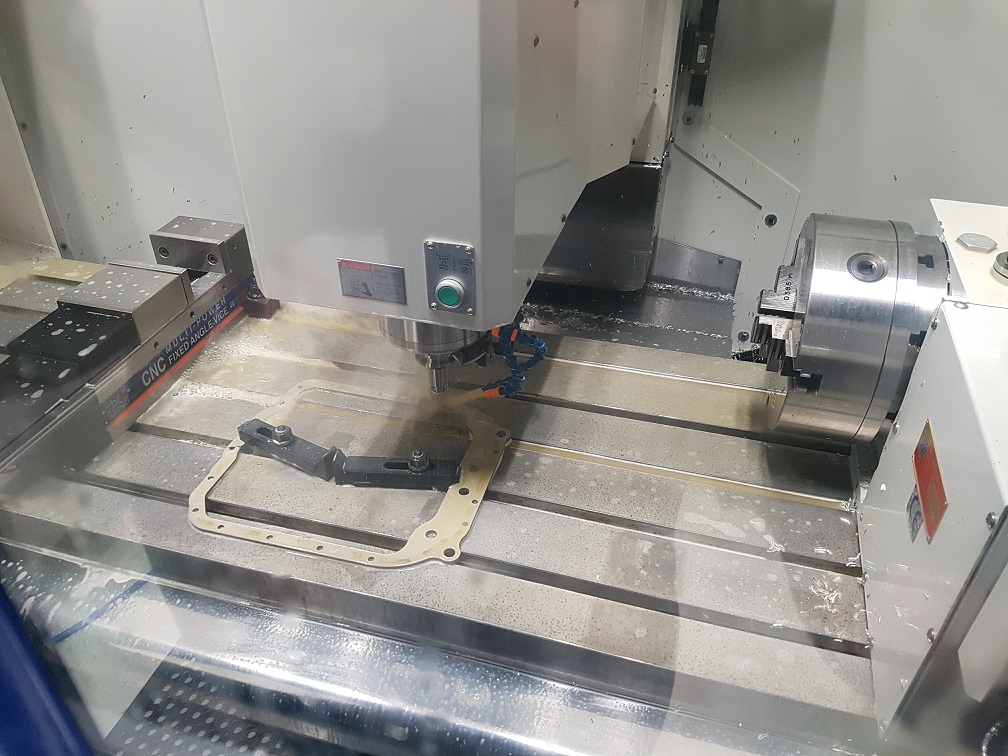
Yeah, an example of brilliant fixturing once more, but it worked and didn't chatter... much.
Was my first time machining stainless, with a 3mm end mill none the less. No breakages and actually a really good surface finish. GWizard is my friend. I grabbed some new fastening hardware, as the bolts originally holding the sump on were a bit of a eclectic collection. A coupe of them were actually too long and weren't clamping the sump flange at all, no doubt contributing to the leaky leaky... A thorough cleaning later, tapping out all the holes to remove old sealant and the sump went back on. There was also a broken 6mm tap incident that put a hold on play for a couple of days till I figured out how to get it out... heh. I used grey 3-bond sealant, as it is 100% the best stuff I've ever dealt with. Its one of those products that has a distinctive smell. You know if you ingest of inhale it, its going to be really bad for you, so that means it must do a fantastic job. Honestly though, if you're sealing a sump on, its the only way to go.
So that will be the oil leak from the rear of the sump fixed, woohoo. The engine mounts will now be sitting 1/4" lower then they were (thickness of the sump brace), raising up the motor 1/4"... However, when I took the motor out I wasn't really happy with the condition of the factory mounts. They were 'ok', but could be better. Some googling later, and I discovered that factory replacement mounts are really really bloody expensive! Some more googling of engine mount suppliers, and I found that 1979 - 1997 land rover engine mounts are a similar studded hockey puck design, and almost expactly 6mm shorter than the factory RX7 mounts... Perfect, that'll sit the motor back in its original location :-).
I'll post another update later on with some info on where the intake / sensor system is up to, and the turbos. Cool stuff going on there :-).
Cheers all.
-
13
-
Whoops, not too sure how that actually got posted. There were pictures to go with it and everything, but then there was pizza, and wine. Hmmmm wine...
To be continued.
-
Whoa, those baby-things take up ALOT of time!
I've managed to get the odd bit done on this though.
To cure the oil leakage issues that FD's commonly suffer from, a sump brace is purportedly the way to go. They're available to buy, but I thought it'd be fun to give making one a go. I ordered a sump flange gasket, with much tracing and scanning later I had the pattern cad'd up, and could cut up a blank on the waterjet at work. We had some 1/4" 316 stainless plate at work, and I figured that would be good to use. Wont go rusty, and it pretty damn stiff. Kind of heavy, but most of it gets cut away anyway...
-
2
-
-
Most 3 phase VSD/VFD's out there will run with only a single phase input (however, you need to de-rate them to about half their stated power) and output a happy three phase for your motorvation needs.
-
1
-
-
I know you're all about the OG, but an aftermarket radiator for an S13 that came with an SR20 is a pretty easy swap into these. Size is right, outlets are right, just needs some mounting points added to bolt to the front support, and a bottom support fabricated.


")


") ), so it's really clean. Currently with a local engine machinist getting a quick skim. Then I can assemble it and get the long block finished.
), so it's really clean. Currently with a local engine machinist getting a quick skim. Then I can assemble it and get the long block finished.


Zac's 1981 L200 Sport
in Projects and Build Ups
Posted
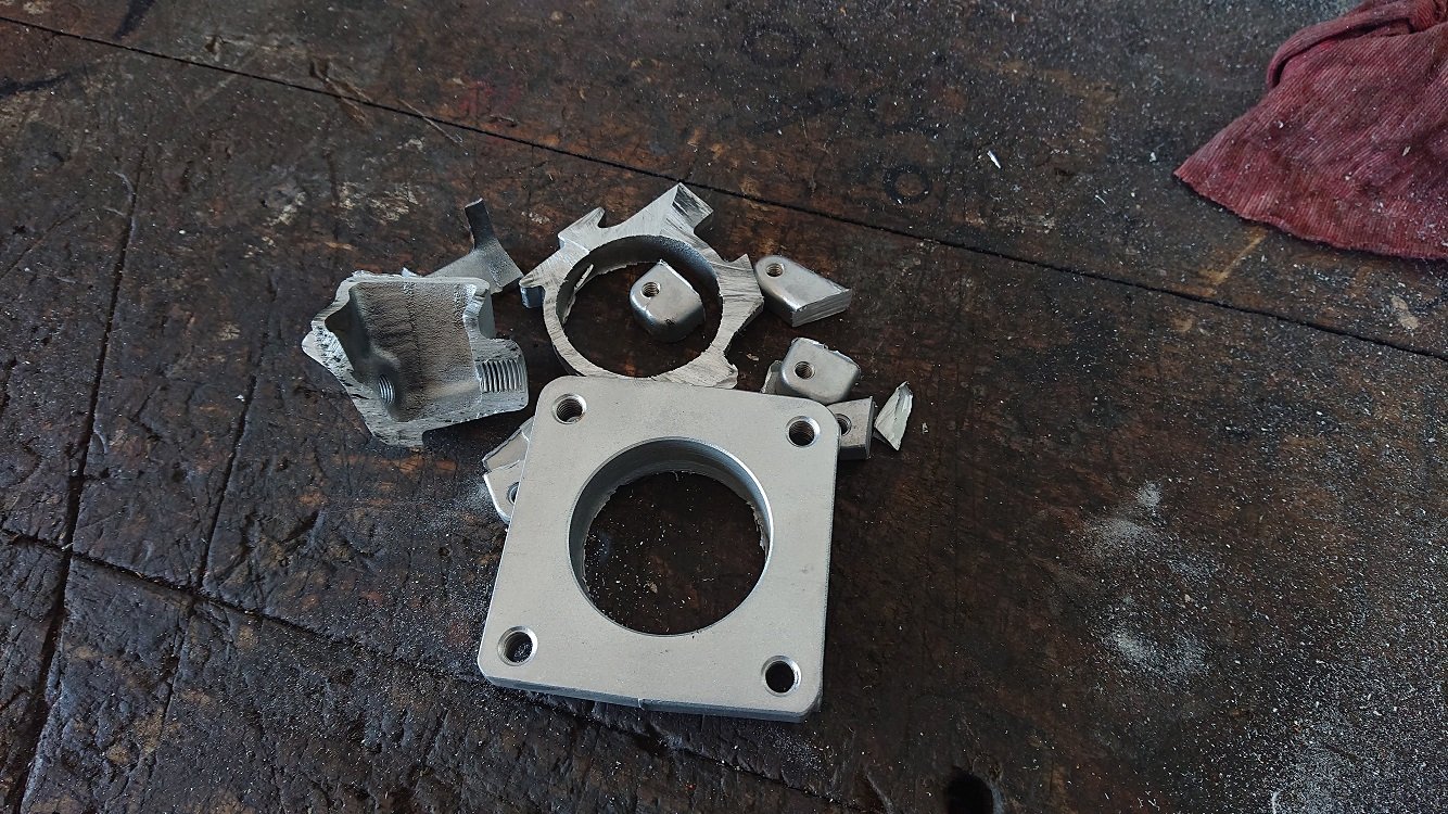
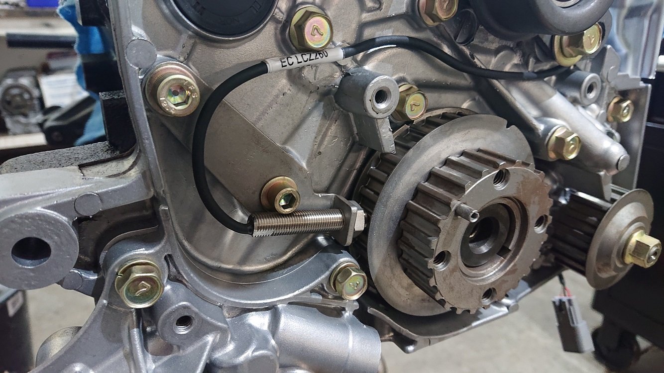
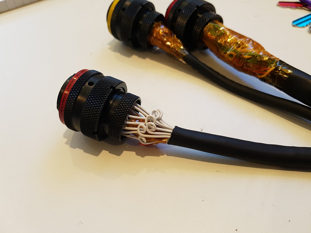
A couple more hours on the intake manifold side of this today, decided to tackle the cam trigger. I got hold of an old distributor from a carby one of these motors. It was missing pretty much everything, just a bare housing, shaft and advance weights still there. I attacked the shaft and housing with a hacksaw to get it down to just the bits I might need. I'm making this up as I go along, so I hope it works out ;-).
What I'm trying to accomplish here is to mount a threaded hall sensor in such a way that it picks up a trigger signal once for every camshaft revolution. Ideally I'l love to mount something behind the cam wheel at the front, but there are no mounting points there, and although I could drill through into the head to make some, I'd enter a water gallery for sure and I don't like my chances of sealing that up afterwards. I thought about maybe picking up off the back of the cam via a custom mount that takes the place of the half moon seal, but there isn't a lot of room to work back there either. I also didn't like this idea in the end as the trigger disc would have to have a pretty small diameter, and as the trigger wheel you're reading gets smaller (so triggers are closer to the centerline of whatever is rotating) a small error in the point the trigger is detected can actually be a pretty large number of engine degrees. The dizzy rotates in line with the cam, so if I can make something tidy here, its about the best compromise I can think of.
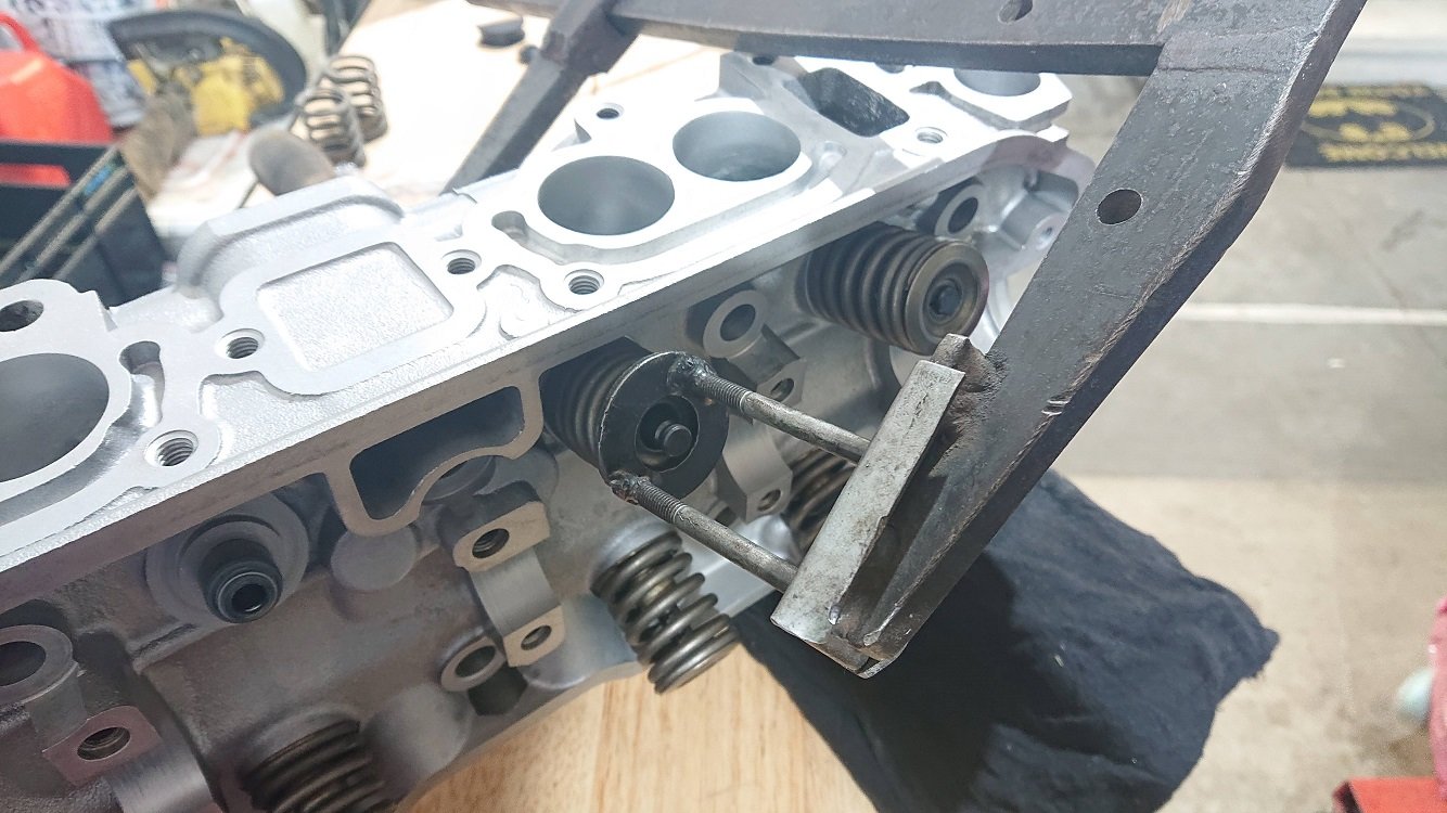
Looking at the cut apart dizzy, I liked the look of those four pads radially spaced around the housing, I figured I could clean it all up, drill and tap those for M4, and make a cap that attaches on and holds a threaded hall effect sensor. The shaft itself can then be tidied up, drilled and tapped for M6 to give a good mounting point for some sort of trigger wheel (with just one tooth :-).
Some time on the lathe and drillpress later, as well as a quick 3dprint to prototype a cap (will either print the final one out of some material that can handle the jandle, or machine out out of aluminium), and I think it's going to work. Not as tidy a solution as I'd really like, and you need to be aware that if you ever remove and refit it, you'll need to reset the base timing most likely, but I think it'll work :-).
The trigger disc can just be made out of a bent piece of steel, will make something tidy for it. There is a bit (I'd like more!) space to squeeze a coolant neck out next to it aswell.