Hurmeez
-
Posts
341 -
Joined
-
Last visited
-
Days Won
1
Content Type
Forums
Downloads
Events
Gallery
Everything posted by Hurmeez
-
You raise a bloody good point...
-
Just to prove that I have been doing shit, behold the passenger side chassis leg in all its Ferrari red glory...
-
@yoeddynz You make a very convincing argument regarding the MS. You may have swayed me for now but I'll keep an open mind and keep looking at all my options, though perhaps now with greater emphasis on the Megasquirt path. Regarding something you mentioned a few posts back, I have been trying to think about how I'm going to handle the coolant system. If I use the stock setup I'm not sure how I can route the line from the back of the block to the radiator while still keeping it nicely packaged. How do most people handle it? I'm considering a custom design that deletes the pipe that runs between the cylinder banks and shifts the thermostat to the front. It doesn't look like it will be too involved with only some fabrication involved. I also have the option of 3D printing a thermostat housing and getting it cast in alloy, similar to the intake manifold I made for the old pinto motor, which would make for a very neat solution. Shifting the thermostat to the front also gives me more space at the rear of the engine which will let me set it further rearwards, which is always welcome. @Transom thanks heaps for those. They should make the conversion much simpler and fully renewing all the gaskets will be good for piece of mind as to the condition of the engine. @Testament yeah I suppose I may have set my expectations a bit high, though to be fair, the old copper based stuff I was using used to work just fine with the TIG so go figure.
-
@Transom the donor car was a 98 model with the GW5R chassis code that (according to the internet professors) should have come with the ZE motor. This is a photo I took of the stamping on the head which shows them to be from the DE engine. Apparently the ZE should have KL31-101 rather than the KL-101 that I have. You can also see the square intake ports that are supposed to be a feature of the ZE heads, rather than the oval ones that apparently come on the DEs. I also pulled the cam cover off to check the stamping on the cams and that was that of the lower spec model as well. What is perplexing is the fact that the intake manifold that was on the engine was the one off the higher spec motor. It looked like the one on the left in this photo, rather than the lower spec one on the right. I also found another car with the same GW5R chassis number that when I looked at it turned out to have the same stampings as this block so I don't know. Again according to the wikipedia, the KLZE was also exclusively put into the Australian model Eunos 800 with no record of the lower spec DE ever being installed. Of course now I'm back up north I've found that there is a Eunos 800 at the Mangere Pick a Part but I can't justify making a special trip all the way down to check it out. If anyone is willing to go and have a squizz for me I'd happily reimburse them for their troubles. If you could find the part number for that front pulley I'd be super grateful Transom. @yoeddynz I'm not sure what I'll do for an intake just yet. ITBs are really appealing but from what I've heard it is difficult to get them setup without paying an arm and a leg. I really like the idea of a twin plenum cross over tunnel ram style of intake, if for no other reason than it looks super bad ass. Or maybe something super sexy like this, But if I can find a set of ITBs for not too crazy money then I'll probably go with them. That said, I'm about to contradict my own cost based argument... Regarding using a Megasquirt to run the engine, I talked to my father in law and he has a particular hatred for them for some reason. He strongly recommended I go for something like a Link Atom instead. He reckons the Megasquirts are real pains in the ass to try and deal with tuning wise or something and apparently the Links really are worth the extra cost. What are your thoughts on it? I know you are a fan of the MS but what is it really like to learn to use and fiddle around with and so on?
-
So it's been nearly a month. I suppose an update is in order. Be warned this is going to be a lot of words with not many pictures, but it's good to blow to dust off the old grey matter every now and then with a bit of reading. Firstly a quick update on the fabrication front. I've made decent progress on the passenger side chassis leg replacement. It was much easier to do the second time round once I knew what I was doing. I made quick work of the outer skin giving it all the appropriate modifications and "crumple zones," same as the other side. Same story for the inner rail with giving it the pressed in weak zone and welding in the crush tubes for the ARB mounting brackets. I didn't take many photos of these processes because it looks very much like the first time I did it and ya'll don't want to see a bunch of repeats. I got to the stage where I was ready to weld each skin together but I ran out of weld through primer so I had to nip to the shops to pick some up. They didn't have any of the previous copper based paint I had used and what's more they don't stock it anymore so I had to take what I could get. Turns out that was this: For anyone hoping to use it, don't. It's awful shit. I followed the directions on the can and sprayed everything down that I was going to weld in the correct way. Then I got everything mocked up ready for welding and started pouring in the amps with the TIG to plug weld in the reinforcement/locating plates just like the first time. It fizzed and farted when I struck the arc and generally made a mess initially. Then it was very difficult to get it to form a weld pool and once it finally did it would sit for a second before making a big pop and splashing up all over the electrode. I'd regrind it and try again but eventually it got so bad it got the gas cup red hot and broke a big chunk off of it which fucked it. Unsurprisingly, this pissed me off. So I tried using the MIG. It rendered similar results. Zero penetration and ugly ugly welds. I also ran out of time and had to ship off on holiday with the family so that is as far as the fabrication got. Meanwhile I made a bit of a start with stripping down the V6. I got rid of all the luxury equipment (power steering and AC pumps) and pulled the alternator off as well; basically getting the motor back to its bare basics. I realised that contrary to what I had been told, it is actually the lower spec 160ish hp engine with lower compression, less aggressive cams, and slightly worse flowing heads. I can't say I'm super surprised but I am still somewhat disappointed. On the upside the lower compression lends itself better to some mild boost down the road but for now I'm going to keep trying for the higher spec NA motor route. I had a look around one of the Pick a Parts in Auckland while I was down there doing other shit but didn't have a lot of time to look very hard. Although there were a few lower spec engines, I didn't find what I was looking for. Unfortunately it's a long way for me to drive to check on every new car that turns up at the wreckers so for now I'll have to soldier on with what I have. I can still use this motor for making up mounts and so forth but it means I'm still on the lookout for a KLZE engine if anyone can help me out. To keep moving forward I got the newly stripped motor hung up on the hoist and swung into position to have a closer look at how it would fit. I didn't take any photos for some reason but you'll have to take my word for it on the details. The engine fits really well with the front sump having a good amount of clearance to the cross member when the engine is placed as far rearwards as the distributor will allow. There are plenty of tapped holes on the side of the block just begging to be used for mounting brackets right near the stock engine mount posts on the factory cross member. This means I'll easily be able to make mounts that pick up the cross member, rather than doing a chassis mount. This lets me drop the whole front suspension and engine out as one unit if I ever want to. The only issue is that the engine is too far forward. I measured the gearbox from shifter to bellhousing and then measured the distance from the shifter hole in the trans tunnel to the bellhousing mounting holes on the engine block with it mocked up in the bay. The block to tunnel hole distance was abour 100mm longer than the same measurement on the transmission. Ironically this is about the distance I shifted the hole back to fit the old ford 5 speed. This means I have two options. 1: I could cut the tunnel again and move the shifter hole forward again to make everything fit with the engine where it currently sits. Or 2: I could shift the engine back the appropriate amount to put the shifter in the right position to line up with the hole in the trans tunnel. The first option requires me to undo more work I have already done which, while not too much work, I'd rather not in principle. The second means the engine gets set further back in the car. This means I have more room in the front for a radiator and fans, and, ultimately, room for an intercooler wouldn't go amiss. Also, race cars have their engines set way back too so... This means I'll probably have to modify the sump to clear the cross member but that's not too much work. I'll also have to come up with a solution to making the distributor clear the firewall. As it sits now, shifting the engine back will require either the firewall to be modified, or the distributor to be removed. In the process of stripping down the engine I found points on the harmonic balancer and a factory mounting point for a crank angle sensor on the block casting. This means I have plenty of parts to convert the engine to crank triggered ignition and either remove, or severely cut down the distributor to fit the new position. All I will really need is an aftermarket ECU. And an expert wouldn't go amiss either. Luckily I have a father in law that is a very well connected, skilled, and experienced automotive sparky and he had already given me plenty of advice on moving forward down this path. Going aftermarket ECU will give me the added bonus of learning to fiddle with tunes and so forth and really get the most out of my motor. So there you have it. To conclude, fuck 3M zinc based weld through primer, I still want to find a KLZE engine, I have a plan for mounting the engine in the car, and I have a plan for converting the engine to crank triggered ignition. If you've slogged through all of that, thank you very much for your time. More consistent updates to come. Merry October to all, and to all a good night.
-
This has been my week. I have tremendous newfound respect for the late model car guys. What a nightmare trying to work on all the modern stuff! I've spent the last week stripping out the Mazda for all the parts I'll ultimately need to get the engine running in the Escort. This has basically only meant the loom and the in tank fuel pump assembly but to get to them I had to essentially fully strip the interior of the car. With the loom now out I can wheel the Mazda back outside and forget about it for the near future while people buy parts off it until I inevitably take it to the wreckers. That means I can get back to focusing on working on the Escort. I'd love to dive straight in to making an adapter plate and getting the engine and box mated and mounted but I don't want to get ahead of myself. I'm going to get the front end fabrication work completed first, meaning new chassis leg and inner wing on the passengers side just as before so I can put it behind me and forget about it. Then I'll do the engine and box work before I fully mount the front radiator support panels or the front panel. This will let me swing the engine straight into the front of the car while I'm mocking it up instead of trying to tilt and wrestle it down into the engine bay every time it needs to go in or out. Doing it this way also lets me put the car back on it's wheels a bit earlier and I am really looking forward to that, let me tell you.
-
It'll look fast at the very least
-
I did think about that but the internet forum "experts"(when are they ever wrong) reckon you're better off using a yoke off an RX-8 driveshaft and getting a shop to make up a custom shaft. Also, since the stock RX prop is carbon fiber, there is a chance that it can be shortened down to suit and then I have a singe piece CF prop shaft to handle both Nm the screaming V6 will produce. In any case, I found one for cheap so I'll get it home and check it out and go from there.
-
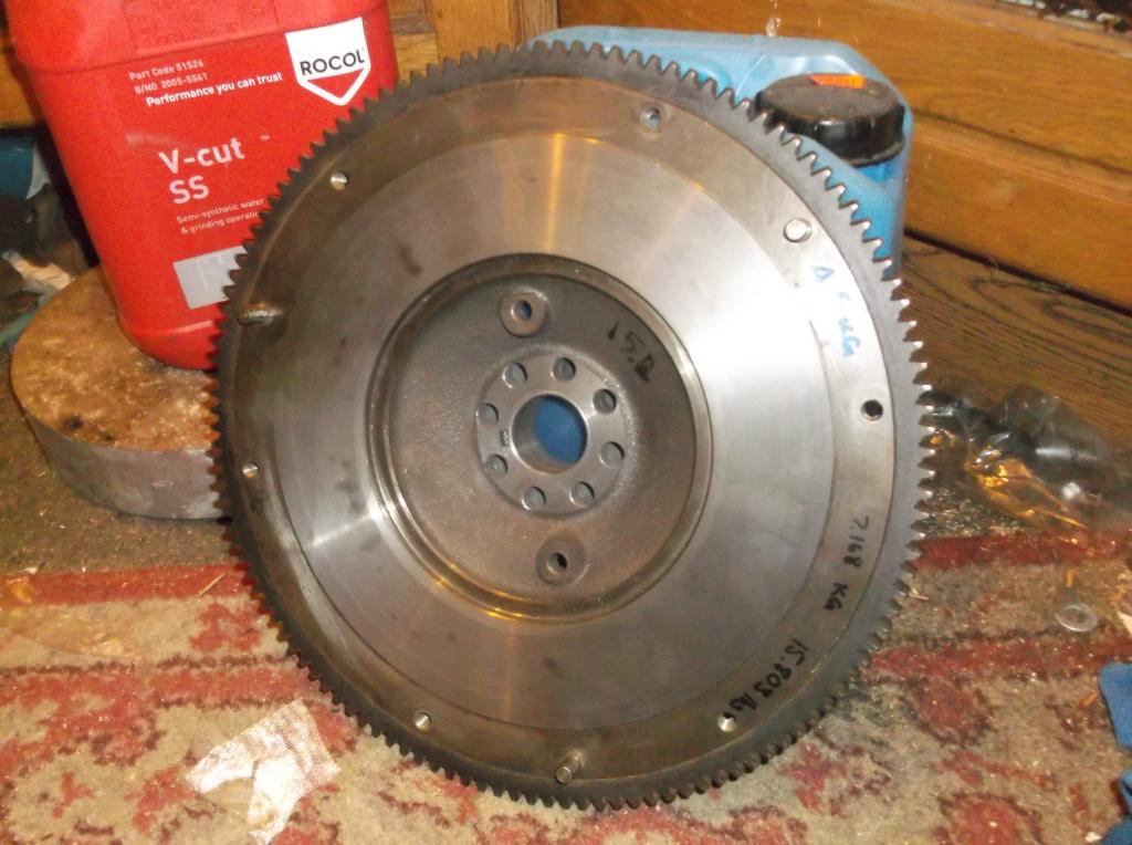
@1963 AP5 A working bee does sound like it would be great fun. I'd be worried that we couldn't get it all pulled in a day considering how long it took me and my dad with full facilities, though I suppose many hands make light work. In any case I'm planning the first trip of a few down to Auckland this weekend so I'll have a look at the candidates and see whether or not they are worth pulling then go from there. @kyteler I didn't even notice how much difference there was in the width of the rim on the flywheel. I see where you are coming from now. That does look like it would be quite difficult to get rid of the offset material and balance everything. Which leads me to @Transom and @yoeddynz's suggestion. I really like the sound of the custom flywheel. It will give me the piece of mind of knowing a dodgy spacer isn't going to break and send a spinning death frisbee at my ankles, as well as the performance gains I'd get from a lighter setup. I've looked into finding a ring gear and it looks like I can source one from this site http://www.ringgear.co.nz/Our_Products.shtml#MAZDA. I've also found a really cheap rx8 flywheel, clutch, and pressure plate that I can use to mock up with a temporary spacer to take measurements off for a custom flywheel. All that's left is sourcing a blank/raw material, as well as finding a machine shop to do it. I'll keep looking into it.
-
Big win tonight! Made a big hole... And filled another... Tonight was focused on simply getting the motor out of the car and by the time that happened it was pretty late so I spent very little time at all putting the engine in the right place. That said, considering how worried I was that it would be a tight fit requiring lots of firewall cutting, I'm very happy with the initial mock up. It is nowhere near the final height in the engine bay, nor tilted correctly fore and aft or side to side, but the over all length looks like it will fit a radiator just fine and the sump shouldn't require much extensive modification. I'll have to get the gearbox adapter plate finalised before I can get the engine position sorted but there's still a few steps before that can happen. Still, progress has occurred.
-
Time for a weekend update. I spent all of Saturday working on my mates HZ Holden ute rebuilding his front suspension with new bushes and ball joints which only left today to work on the Estate. I started by finish welding the whole driver's side inner wing repair section. It all turned out pretty good. I went ahead and ground it all back. There are a few sections that could have been done better but at the end of the day almost every weld line will be covered by other panels so I'm not overly worried. So I cleaned it all down and gave it a quick lick of paint. I didn't put too much effort into grinding back this side since it will all be covered by stone chip so it will be invisible anyway. Then I spent the rest of the day trying to get the engine pulled out of the Mazda. It started out looking like this, And ended up looking like this. We pulled the intake manifold off to give ourselves a clearer view of everything, then started to unplug all the loom connections, labeling each. Ended up getting everything unplugged and moved on to thinking about how to get the motor out. The easiest option seemed to be to pull the axles out of the front hubs and drop the whole subframe out the bottom of the car. The thinking was that we wouldn't have the room to pull the engine off the gearbox so both units would have to come out as one and the easiest way to do that would be the reverse of how the factory put them in. So I set too popping the lower ball joint and tried to crack the main nut off the end of the axle. I used a breaker bar because I don't have an impact gun. This caused my half inch drive to snap off in the socket. Bugger. I called it a day there and decided to have a break for a while. I've had a think about it and a better way might be to crack off and pull all the torque converter bolts to the flex plates if I can get access. Then I won't need to pull the engine and box apart so much to get it out and I might be able to pull the engine out from the top. A job for tomorrow night maybe. On the bright side I've double checked the maximum dimensions and it definitely will fit in my engine bay. That's a relief.
-
Made a fruitful trip down to Auckland last night. Picked up a couple of goodies to help move the project along. I finally have a gearbox to start using for mocking up making mounts and so forth. Considering how huge it looks, it's crazy how similar in size it is to the old type 9 and yet it can handle so much more abuse. You can see I've slotted the driveshaft from the Type 9 into the RX-8 box and the splines actually match perfectly. The issue is that the outer diameter of the yoke is smaller than the RX-8 so it doesn't run in the bearings or seals correctly. So I'll have to find an RX-8 yoke and use that to get a custom driveshaft built. Oh well. You win some you lose some. Speaking of winning some, I got my hands on a more suitable diff too, out of a Mk 4 Cortina. They came fitted with an Atlas axle as standard, the same as those fitted to the Capri, but with different mounting points. The current tentative plan is to eventually get it shortened by a friend of my dad's and then sort myself out a six link setup that somehow retains the rear seat. That's all a long way off yet though in all probability. For now I'm just going to run with the English rear axle and be careful. Hopefully that will let it last for a little while at least.
-
I got a quick bit of welding done last night before work. Not much but it's progress.
-
Alright time to make up for the time I've been away. Prepare for a pic dump for the ages. I've been working on buttoning up the bottom front corner of the driver's side inner wing. In the last post I got the outer skin of the chassis leg all finished up so now I'm working on the other side. I sprayed the inside of the rail and the back side of the bumper mount reinforcing plate before I clamped it up ready for welding. I tried to position the welds close to where they were originally for no reason other than neatness. Then I welded it all on, including some tacks to the crush tubes,. This might seem a bit on the weak side but that's what was holding the original pieces together so once again, good enough for Uncle Henry... And cleaned it all up while I was there. Now it was time to start thinking about fitting up my inner wing repair panel that I made up months and months ago before I realised just how much of a mission all this front end work was going to be. This part is going to dictate where the front valence panel will mount so it's fairly critical that I get it in the right spot. Thankfully, some clever bloke thought about all of this before hand. When I went to all that trouble to make my guards bolt on, I made sure they bolted to the front valence in a way that held it tight to the inner wings while they were still there at the time. Therefore, I should be able to clamp the front panel up to the upper inner wings that I already know are in the right place, bolt them to the guards, and then clamp my lower inner wing repair panel to the valence to show me where it needs to go. If none of that made any sense, don't worry, I took photos. So to start, clamping the front panel to the upper inner wings. Like this. Then bolt the guards on... The repair panel actually jammed in place by itself which was handy. Then I passed some bolts through the crush tubes with some grease on the ends and spun them once they touched the new panel. This put a grease spot in the position of the hole for the crush tube which I could then center punch and drill through. Which gave me this... The holes weren't in the perfect place and the tack welds made it difficult to fit so I opened each hole out with a die grinder until it fit nicelyish. This photo shows what the panel was that I had to work with. It's hard to see properly from this angle but there was quite a gap between where the panels were and where they needed to be in order to butt up together nicely. I decided to bolt up the brake booster mount to try and brace everything a bit and stop myself from pulling things too far trying to make my panel fit Uncle Henry's. Goodness knows how effective it will be but at the very least it makes me feel better about myself. Then I went ahead and opened the hole out further to more closely fit my panel. At this point I started to go the other way and began to trim my panel to fit the hole. Once it was fairly close I started to clamp it into position. Once I had it all fully trimmed up and holes drilled for plug welds I sprayed everything with a good coat of weld through primer. Once it was dry it got clamped up once again and tacked in place with the TIG. I figured now would be a good time to double check the front valance fit before I do all the plug welds. Once they're in it'll be a real prick to try and adjust. Looks pretty good to me. So I set to and broke out the MIG to fill in all those holes. Turned out well. Good penetration all round. And that's about as far as I got. I decided to clean up a bit before I did all the TIG welding fully, as well as pulling out the cross member for better access. So that's it for this week. Next plan is to finish up the welding on the driver's side inner wing then give the fab work a rest for a bit and get my ass into gear with pulling the V6 out of the Mazda. Hopefully the welding shouldn't take too long but these things always seem to for me. I'll be sure to keep you guys posted.
-
I suppose steel will be cheaper as well versus the alloy. Looking at the flywheel, I assume those lumps at 9, 11 and 1 oclock are what you mean by balancing efforts? Surely they'd be simple enough to turn off in a lathe wouldn't they?
-
That's the plan Alex, I just have to get a hold of the gearbox and engine first. I bought the box last night and am just waiting on confirmation on when is the best time to pick it up. As for the engine, I have to pull the car in under the hoist but there's other cars in the way at the moment so much tetris must be played beforehand. I'm looking forward to it though.
-
Thanks everyone for your replies. On the flywheel front, I talked to Claire on the MX5 forums who has done this engine and gearbox combo in the past, and she said that she had no issues with the flywheel being unbalanced. Apparently on the RX-8 the counterweight is separate to the flywheel, whereas the flywheel off an RX7 (which fits the 8 and looks very similar) has it built in, leading to the confusion. Therefore I have decided to go this route with it. That means I won't need to pull the engine out of the 626 down in Auckland, though thanks heaps to @bigfoot for the generous offer. On the adapter plate front, thank you @BigT105e for the suggestion and I totally see where you're coming from but I feel like I wouldn't be comfortable with the amount of accuracy that I would get from doing it that way. Instead, thanks again to @Transom, I found the CAD drawings of the KLZE bell housing bolt pattern. I also found a drawing of the RX-8 bell housing bolt pattern and set the two over each other to try designing my own plate. It's very much in the early stages so far but I'm still chipping away at it slowly. You can see there are some clashes with bolt positions but one on the top left is a locating dowel on the engine side so I might be able to get away with it. The lower one I'm not so sure about yet but I work on it some more and I'm sure I'll figure something out. My plan it to get it to where I think it will work, then cut it out of MDF on the school's lazer cutter to check it will fit, then take it to a CNC shop in town and get them to cut it out of some ally plate for me. It should work out to be cheaper than importing it by a long shot. I'm still open to your guys' thoughts so fire away.

-
No pic update tonight. Looking for advice and opinions. I've managed to locate a gearbox in Auckland which is close enough for me to be willing to drive down and pick it up. It comes with everything from yoke to bell housing including throw out bearing and clutch lever but no clutch, pressure plate, or flywheel. So I'm at a bit of a cross roads. There seem to be two different options for how people adapt the RX-8 box to the V6. They both require the use of an adapter plate because there are no RWD boxes that bolt up the the V6 but I think I'll tackle that issue later on. For now I'm thinking about the flywheel and clutch situation. At the moment the motor I have is bolted to an auto box so I'm going to need to find a flywheel of some sort. One option is to use the rotary flywheel with a spacer adapter to take it from the single nut used on the rotary motor crank to the six bolts used on the V6. This is clairetoo's flywheel she did for this conversion. This option has the advantage of retaining the stock rotary clutch, pressure plate, and starter motor position and I already know where I can get the whole lot with minimal effort. The other option used by Alex in his Viva is to use a stock (or aftermarket) V6 flywheel with a machined spacer to bring it out to the correct position relative to the gearbox input shaft. I believe he used the V6 clutch and pressure plate which matched up the the rotary input splines. The complication of this method is that the starter needs machining to bring it in toward the flywheel center because the flywheel is 10mm smaller in diameter than the rotary one. Also I can't find a V6 flywheel anywhere but in a 626 in a pick-a-part in Auckland. Normally I'd be happy to go and pull it but I don't have an engine crane to pull the motor, and it's a long way to go. I'd be worried that I couldn't pull the motor in a day and then I'm stuck in Auckland overnight with a half pulled engine. So at the moment I'm leaning more toward the rotary flywheel because it keeps things as simple as possible and keeps the most stock parts on the car which is always a good idea if I ever needed to do maintenance. But there's one thing holding me back. I've read online that the rotary flywheels have a counterweight built in to balance the effect of the dorito wobbling around in the engine. I'm thinking though that putting that on a regular piston engine it will be totally out of balance and make a mess of everything. Does anyone know if this is the case? At the moment I'm pretty sure it shouldn't be an issue simply because Claire has already done it on her project. Finally, I'm thinking about building my own engine to gearbox adapter plate. I've looked at how much it would cost to import one from the UK and right now I'd rather have a go at making my own. I have access to a big milling machine for drilling the actual holes so I'm not too concerned with that aspect, but what I am not completely sure about is how I should go about measuring the positions of the holes as accurately as I'll need to to ensure a good mating between the two components. I have some ideas but I'd be keen to know your guys' suggestions. Phew! That's it. If you've made it this far and actually read it all then well done. I'd be only too keen to hear everyone's opinions. Chuck it all in here:
-
I feel like I'm saying this every update but not too much done today. Lots of balls in the air so to speak. I started with putting a bunch of holes in the outer rail skin with a step drill to plug weld it to the inner channel. Here it is all clamped in place. I gave both inner faces a couple of coats of weld through primer to help to keep the corrosion at bay. You can also see the ARB mount bolts in position to make sure they'll be able to easily slide in and out once it is all welded up. Then I welded the lot up with the MIG. It's much faster for these sort of jobs and far less involved than the TIG. While I had the MIG out I also went and spotted the butt joint together as well. I was originally planning to use the TIG for this part but I've only got the one gas regulator between the two machines and I couldn't be bothered swapping it over. No matter, the MIG will work just as gooder. It's not very in focus but such is life. You can see I've started to grind back the plug welds too. Finally I got the whole lot ground back and gave it a lick of paint. Not too bad. I reckon if you didn't know, you'd never know it'd been touched. That's all for today. I won't be working on it tomorrow because I have exams all day but I should be back into it on Friday. That is all.
-
Time for today's update then. I didn't get as much done because I had an exam but in the time I had I was quite happy with the progress. I started off by making some holes in the existing chassis rail. I cleaned inside the rail with a die grinder and solvent before I sprayed some weld through primer to try to keep the exposed steel to a minimum. Then I cut and clamped some 2mm plates inside the rail ready for welding. The idea here is for the plate to act as both a reinforcement, and a locating mechanism to hold the channel in place while I butt the two channels together. So I turned the TIG up to 11 and set to joining everything together. The green colour is from the weld through primer being messed up by the heat of the weld. These are the hottest I've ever had my little TIG; I'm trying to make sure I get some good penetration into the 2mm plate. Once all three plates were in I was able to slot the new channel section on and double check all the measurements. I wanted to be doubly sure that everything would line up nicely so I clamped everything to the angle iron again. Then I added another clamp to hold everything laterally and went ahead and welded in the rosets. And wire brushed it off all pretty like. Finally I could get to the actual butt welding. I left the welder cranked way up because I didn't have to worry about blowing through thanks to the backing plates welded in behind the joint. Almost like I planned it... Looks pretty good to me. All cleaned up, And painted with a quick spritz to stop any flash rusting. This was the last bit I got done on the Escort. Tomorrow I'll clean back the inner channel, hit it with some weld-through, and weld the outer skin on. That's the plan anyway. Meanwhile, I did a bit of work on the Mazda to try and sort out the trans issues. Remember, I do want to daily this thing if at all possible until the Escort is ready to take its guts. It's a really nice car after all. I started off talking to the transmission expert friend of mine (wouldn't really work if I called him the "trans guy," would it?). He suggested it may be a stuck valve of some sort preventing hydraulic pressure from getting to the valve body and letting the trans select a gear. He gave me a set of instructions of how to pull this valve and clean it up to see if that would help, then left for a while to go and run some errands. I pulled it out and hit it with some wet and dry as instructed before I reassembled and tried to put it in gear again. Still nothing. Kaput. Still, I was warned this might be the case. If it was, I was told to unplug a certain hose from the trans and run the motor to drain the trans of fluid before I pulled the pan off the trans to look for any shrapnel. So I did. Pulled the hose, ran the engine, got much less fluid than I expected into the waste oil container. Curious... I just assumed there mustn't have been much fluid in the trans. Maybe that was the problem in the first place. In any case, I'd drained it so now I went to pull the pan off. These bloody modern cars man! What a pain in the ass! Eventually I managed to get all the bolts out after wrestling around a cross member for too many minutes. Then I belted the pan a couple of times with a rubber mallet to break the gasket and get it off. Then it came off. Full of trans fluid. Shit. It may look like I decided to work on it in the barn for today but in reality that's all the sawdust I had to throw down to soak up the fluid. Once I had that mess dealt with I got to have a look inside the pan. This is what I saw. Now I like glitter just as much as the next man, but when I have that much of it, and in my trans fluid, I tend to get a bit upset. The two magnets were absolutely covered in chips and shrapnel and the oil itself had a very pretty sparkle to it. I don't think I have to be an expert to say she's toasted. I talked to my mate again and he said it's going to need a very extensive rebuild in the least, a new trans at worst. At the moment I'm thinking that it is going to be a pull the engine and sell the rest as parts job like I originally intended. And I'm ok with that. That said, the guru has offered to look for a new trans for me for much cheaper than I'd be able to get it due to his connections so there's still a slim chance of saving it. I think I'll probably just take the selling it as parts option though. It'll probably save me a lot of headaches. I should know for certain tomorrow anyway.
-
Today's work so far... I started by measuring, marking, and trimming the inner channel to the correct length. It didn't take too much fiddling which makes a nice change. I used a piece of angle iron to keep the channel parallel to the top of the original for checking the fit. I got it trimmed up properly and mocked the two skins up together to check how they'll sit. Looks good. Next I had to transfer the positions of the holes for the ARB mount crush tubes from the outer skin to the inner one. Easy peasy. Then I got them drilled out and test fitted the tubes. Should fit nicely. I gave it a couple of tacks with the MIG from the inside to hold it in place, Then fitted the bumper mount brace panel to the back side to stop the tubes from pulling to one side or the other... While I fully welded the front side with the TIG. The tubes stuck out slightly proud which meant I barely had to use any filler. Then I cleaned up the welds and put a drill back down the tubes to clean up any spill over of the weld bead. Finally I assembled everything to check how it would fit, I measured the position of the ARB mounting bracket relative to the other side which is as yet unmodified. So far they are dead nuts on so I'll go ahead and get this side tacked in. Not before I disassemble it all again to put some paint up inside the rail though. I'll put some topcoat on before I weld it in. I've stopped for a quick lunch now but I'll be back out there real soon.
-
Thanks Alex. I'm sure I'll be coming back to you with plenty of questions in the future.
-
No actual progress today. Sat around at the accident clinic for three hours waiting to turn this Into this. It's a bit bloody over kill but such is life. At least it was free. In future I'll just fill it with antibacterial goo and tape it up. It would save so much time. Oh well. I have school off tomorrow so I can get some work done then.
-
The Mazda is home now and it's in really good nick. I didn't realise quite how nice a car it is. It has cruise control, climate control, AWD, sun roof that both slides open and tilts open, heaps of leg room for the back seats, as well as the big boot. When we towed it from the transporter company depo it went into gear to begin with, then I put it back into neutral and it wouldn't go back into gear after that. It was making a horrible death rattle noise from the trans for some of the tow and nothing at all for others. Messing around with it today, it felt like it was in park for all the gears and rocking it back and forth did nothing until it popped and started rolling. It still wouldn't go into gear though after that and would just roll down the slight slope that it is parked on. I'm going to talk to the transmission man up the road tomorrow to see what it would cost to sort the trans out because I'd actually really like to use it as a daily now I've got it. That said, if it's not just a simple fix and going to cost big bucks to fix, I'll pull the engine and sell it as parts. It'd be a shame really but that's the way the cookie crumbles. In other news, I did some more work on the chassis leg repair channels this evening. If you remember back to earlier in the week, I folded up the inner channels and managed to put a fold in the wrong bloody place to fit properly in the outer skin. Tonight was spent trying to remedy that. This is the before shot. The plan was to hit it with some heat and try to flatten out the fold. Doing it cold would probably make it crack so hopefully the heat would help prevent that. I didn't take any midway photos because I was busy juggling a gas torch but I'll put a stop to your waiting and show you the end product. It's a little warped but nothing fatal and it should pull straight once it's been folded up again. Next job was to put the fold back in but in the right spot. I measured the inside of the outer skin panel and did a little bit of maths as an excuse for the guess that actually gave me the new measurement. Then, not having a sheet metal brake man enough to do the 2mm steel, I moved over to the press. I made sure to line everything up perfectly before I started and checked it against the other one while it was only bent through a small angle to try to catch it early if it was wrong. Once I got it started in the right place on the two round bars, I moved over to the V-block you can see to the right of the picture and finished the fold. It turned out like this: Which is to say snug as a bug in rug. Perfect. By using the same method as the outer skin I put the cut-aways in the same places as the stock car. This is, step drill to make the radius, then cut the extra steel away and clean it up with the flap wheel. Then I quickly zapped up the seam in the lower (upper in the previous photo) flange to finish off the overall folding part of the job. I quite like using the TIG on this heavier gauge stuff. Something about 70 odd amps going into it is just so satisfying. I subsequently ground this back to clean it up nicely too. Next was to add the "crumple zone" kink with my fancy custom press dies. I lined everything up as best I could and started to press it in. In hindsight I should have done it the other way up because to begin with it just folded it into a V shape and it wasn't until I flipped it that it came back to straightish. This is how it turned out "hot off the press" (see what I did there?). And this is after some fettling and dicking around to make it fit again. I'm happy with that. It'll definitely do the job. Next I trimmed off some excess along the top flange using the tin snips. In hindsight, I should have just used the grinder because the 2mm sheet is a pig to cut with the snips. Especially the last little bit. Especially when you slip at the very end and slice your finger right open and bleed all over the shop. So now my finger looks like this and I'm going to get it cleaned and dressed at the clinic tomorrow. I've got popsicle stick splints on either side to try to stop me from bending the knuckle and opening up the cut. I even managed to catch my ring finger but not nearly as badly. So the plan for tomorrow is to get my finger sorted, then finish getting the inner rail final trimmed and offered up, possibly even tacked in place. Also I'll get the transmission man around to have a look at the Mazda if possible. Let me know if you want to see a video of it not working and I'll chuck one up. Someone might have an idea. For now though, I'm going to focus on not bleeding and catching some Zs.
-
Folding up the channels had some mixed results. I got the first folded up with a bit of fiddling around but it turned out good. The second must have been not quite on the line or something but it came out slightly to big to fit properly. This is both channels fitted into the outer skins. This photo sort of shows how the second one doesn't fit nearly as good as it needs to. My plan is to try to heat up the fold and flatten it back out so I can refold it in the right place. Failing that, I have more steel so I can always just make another one. I'd rather not waste it though. Sorry for the small update. The Mazda should turn up tomorrow. Should be fun.