

Hurmeez
-
Posts
314 -
Joined
-
Last visited
-
Days Won
1
Posts posted by Hurmeez
-
-
Next I made some repair panels for the front of each chassis leg. They were fairly simple. Started with a cardboard template then transferred it to steel and folded the lot up. There is actually an inner and outer piece to each of these just like the factory chassis leg to add rigidity but I didn't get any photos of the inners.

This is the chassis leg and front panel sitting in place. I haven't removed the rad supports yet because I wanted to make all the replacement panels first in case I chop out the old panels and everything moves around and I don't know where to build to.
I have to keep making posts with just a few photos because they're too big file sizes. I thought I was being clever at the time getting the highest possible quality photos from my phone. It's biting me in the bum now.
-
 3
3
-
-
Actually nah screw that I'm gonna keep going.
Once the front panel was off the true extent of the corrosion in that part of the car was obvious. So more fab work was called for. I started off by making a new radiator support/front panel mount. I folded the main bend first then used a slitting disk to split the fold in the middle part where the rad mounts. Then I carefully reverse folded these two new flaps and zipped the whole lot up with the TIG. By doing the folds this way I was able to keep the amount of welding to a minimum and therefore the amount of distortion too. Then it was a doddle to put some plates in to blank off the holes and fold up the relevant mounting tabs and there you go, one piece done.
You'll note the slight curve in the bottom part which follows the curve of the valence to be welded to it. This design is different to a stock escort where the rad cutout wouldn't have been there at all. By doing it this was I have made a neat solution to shift the rad forward in order to clear the longer pinto motor. Mint.
-
4
-
-
Glad you like it 64vauxhall. I'll definitely keep the updates coming, it's bloody addictive once you're on a roll.
-
1
-
-
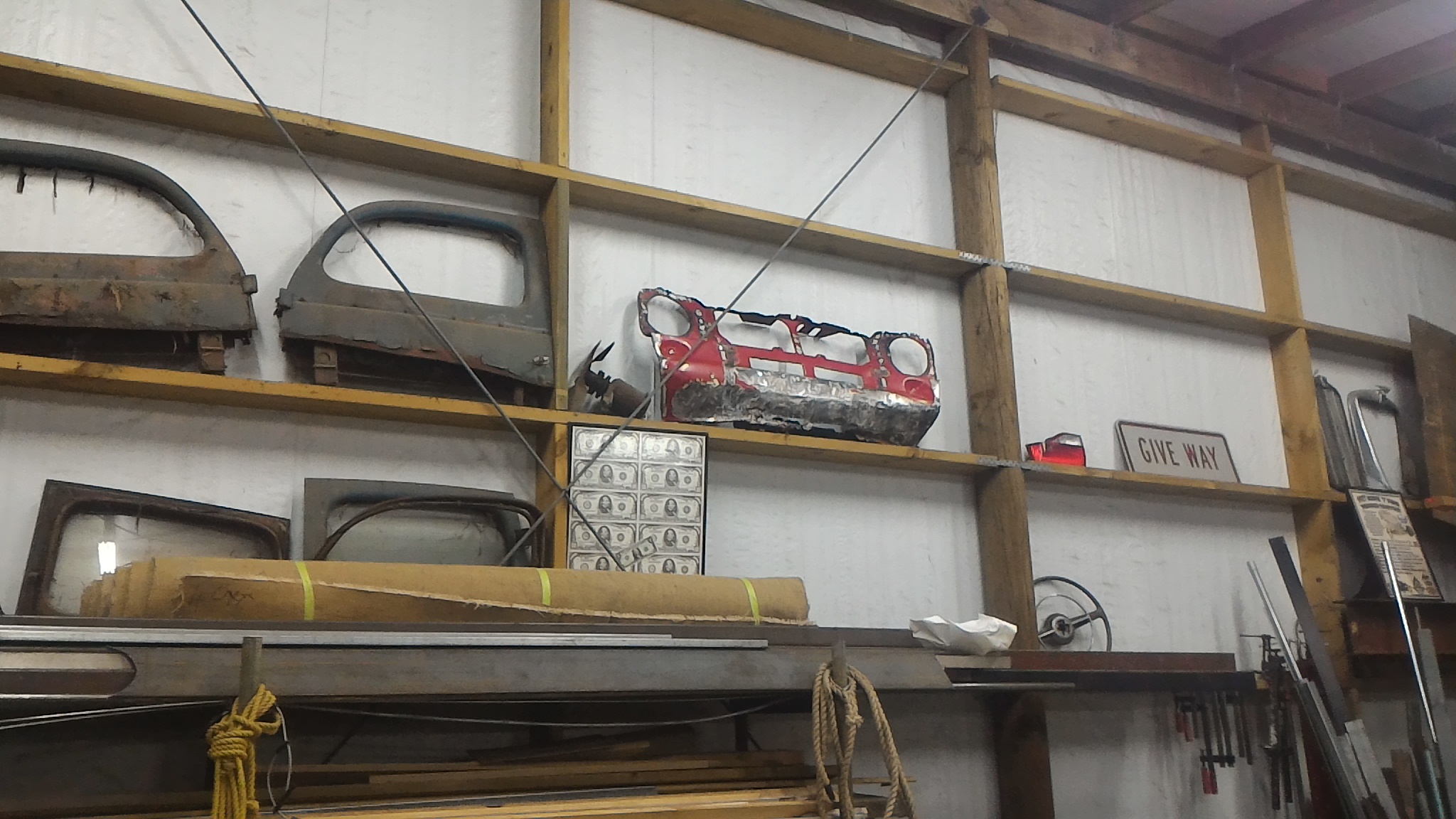
So the only option was to arsehole the whole lot and start again.
Banished to the wall of offerings
And a pretty new one from palmside
I think I'll call it there for tonight. We'll pick up the tale again sometime tomorrow.
-
9
-
-
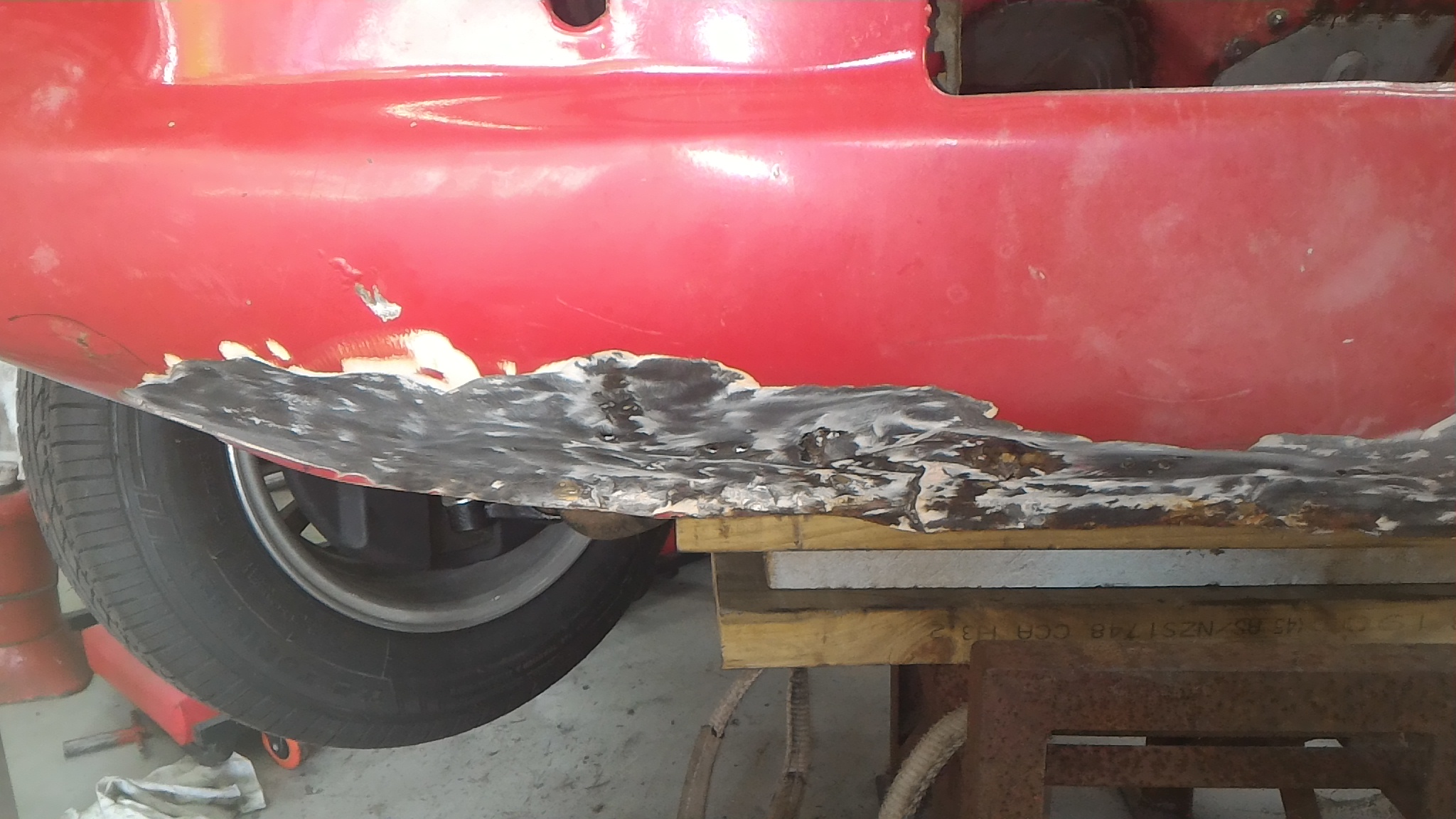
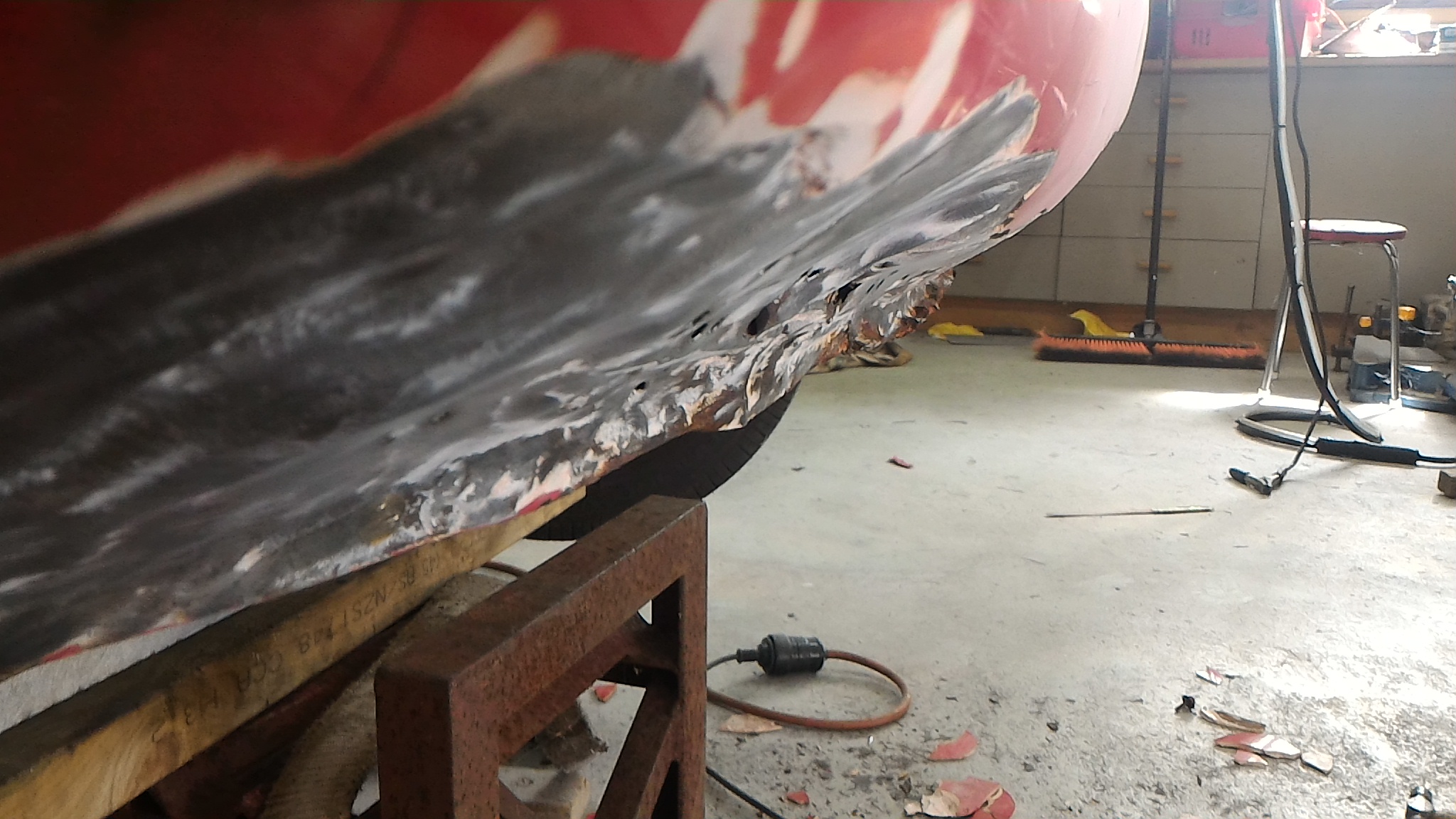
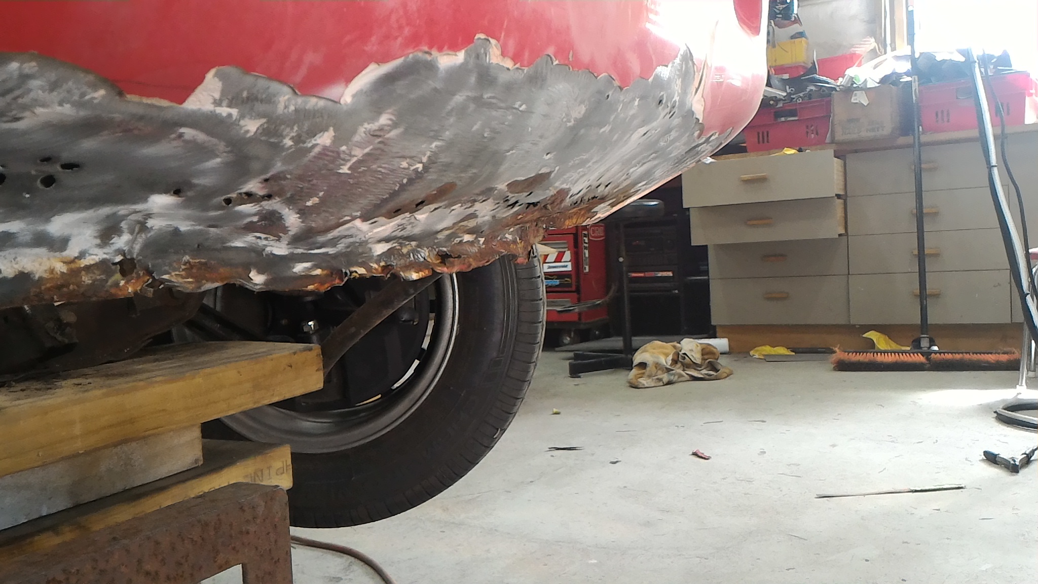
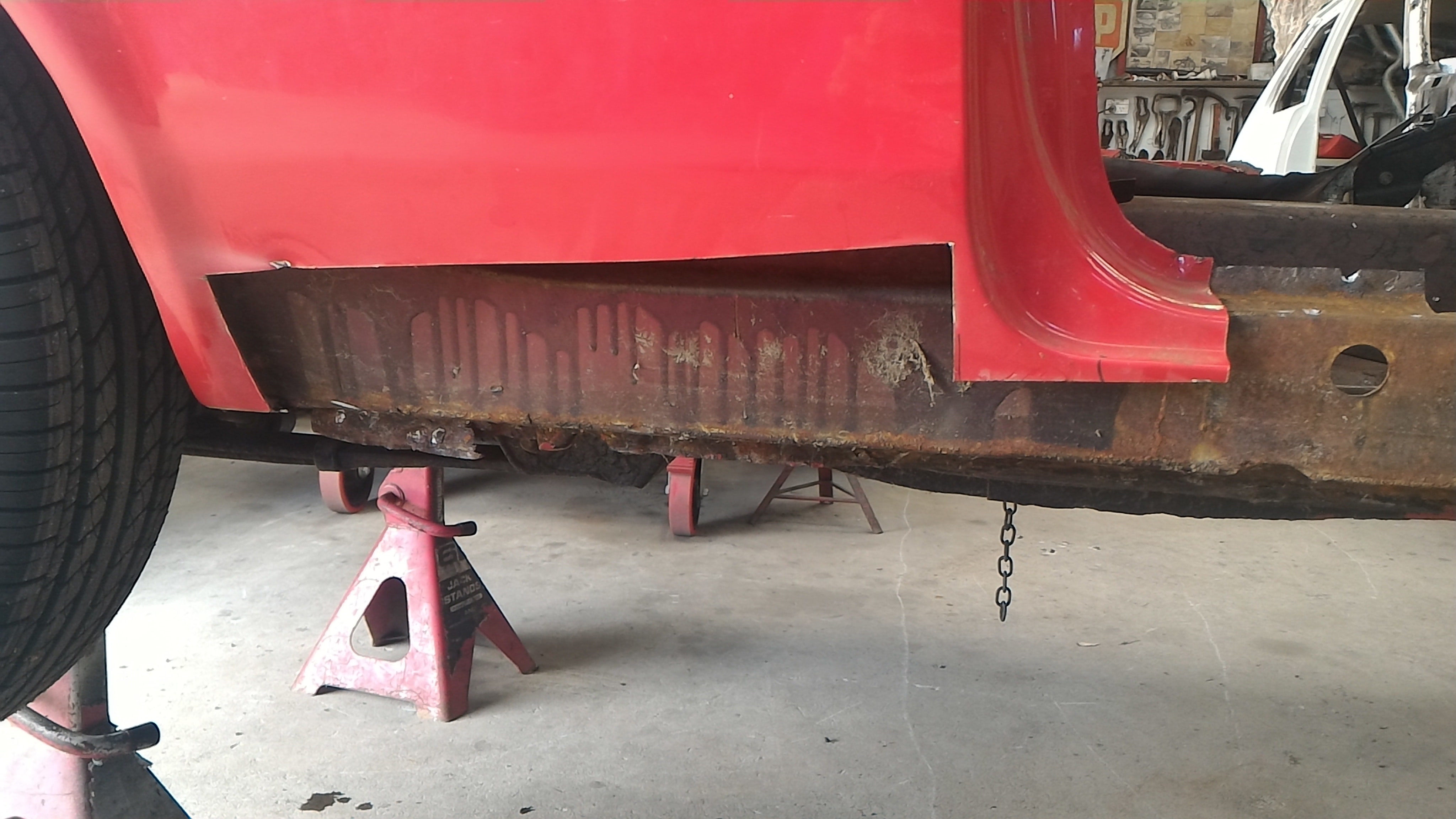
Next thing I got on to was investigating the small amount of rust you could see on the bottom of the front valence panel which you can sort of see in this photo.
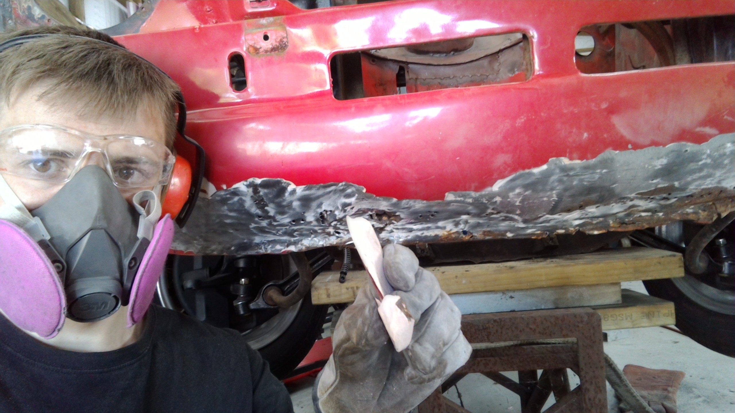
I could see a bit where there was some bog lifting away from the rusting steel underneath. So I put a screwdriver in behind the bog and chipped it out to see how far the bog went. And went. And went. There was a bit of bog on there actually.
That's a size 10 boot and the pile is as high as the top of it.
This is the state of what the bog was covering. The photos struggle to portray just quite how much the panel is pushed in. It was a mess.
This is some of the thicker chunks of bog that came off. Please note that they're directly end on to the camera. That is actually how thick it was. There really are some gifted "panel beaters" out there.
-
9
-
-
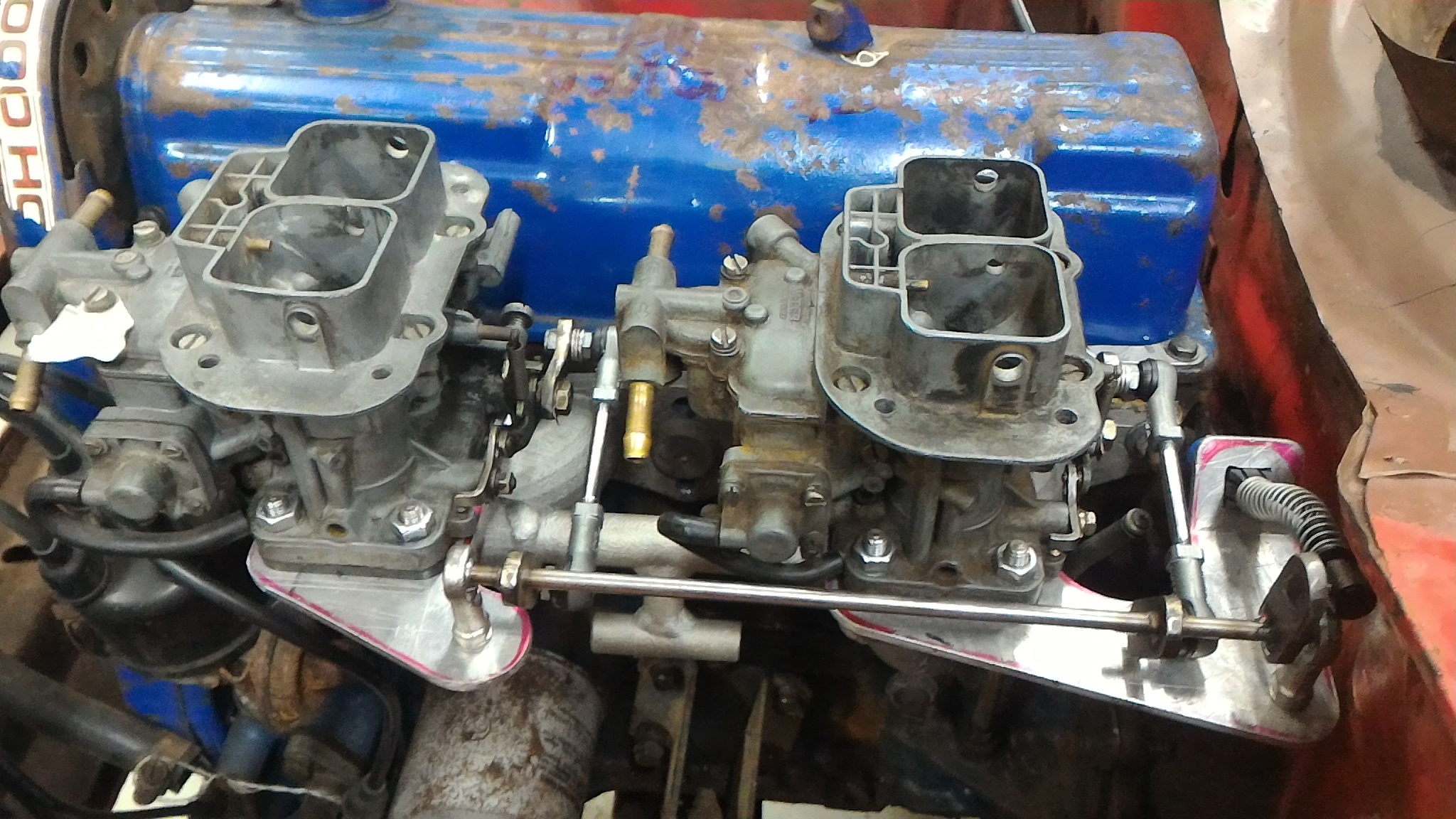
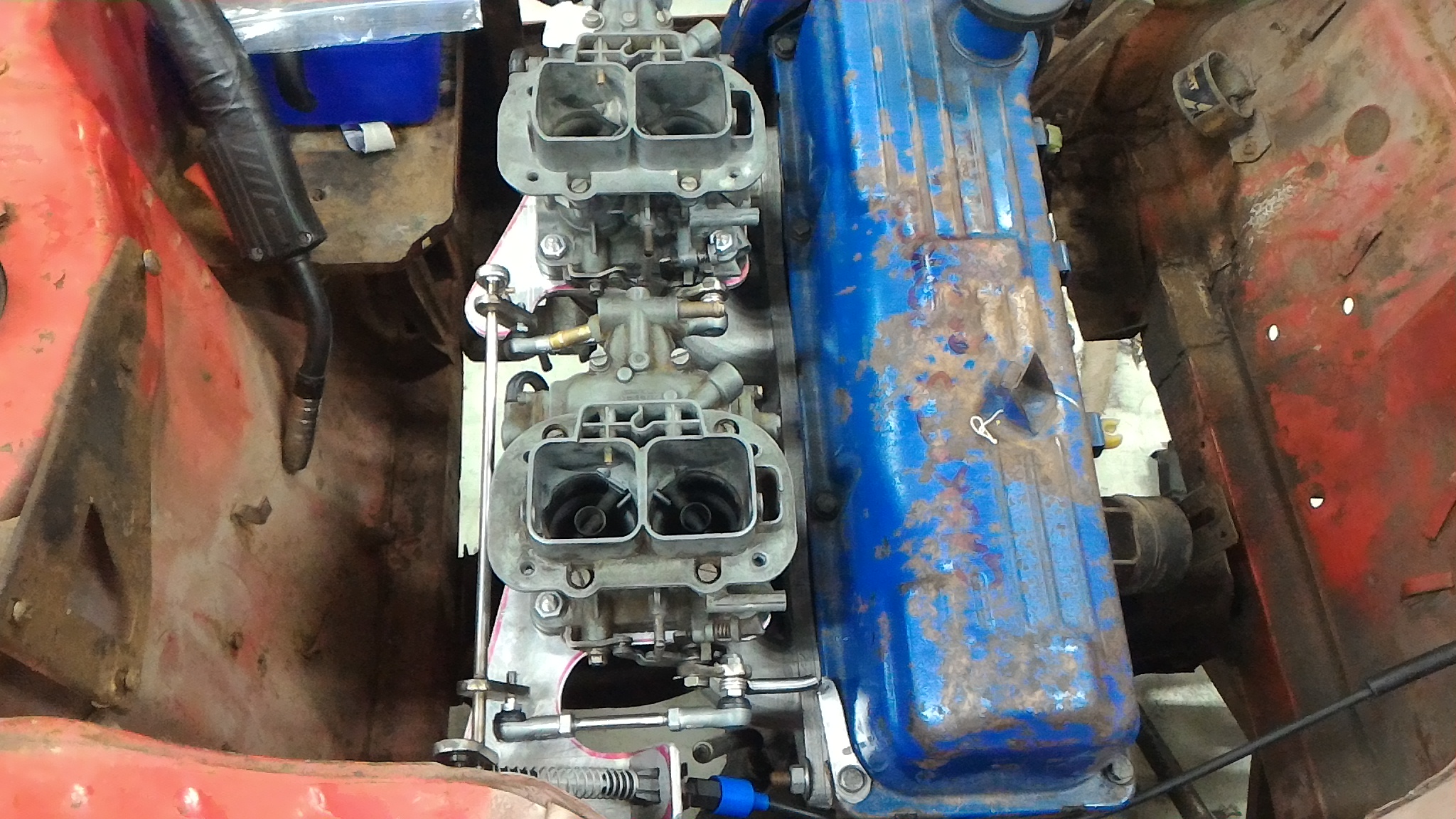
My next mini project was sorting out the twin carb linkage setup. I drew a lot of inspiration from the setup on my dad's 1600 but made a few tweaks. His is designed with the primary venturis furthest from the intake ports with the idea that when the secondaries open they have a straight shot down the thing's neck. In the interest of throttle response I've decided to instead put the primaries closest. This probably has little real world effect but I liked how it sounded.
As you can see from the photos, there is a central stainless shaft mounted by a pair of rose joints, themselves mounted to two alloy plates clamped between the carb and the manifold. Off of the rod are mounted three stainless arms. The first is connected to the standard RS2000 throttle cable. The other two are connected to what I can only describe as miniature track rod ends which themselves are connected to another set, then the final linkage onto the carb. I back of the envelope calculated the lengths of the different arms to give me full pedal travel for full butterfly travel, hopefully avoiding a super twitchy throttle like the one in my dad's car. I also added an extra return spring on the cam cover just in case.
In hindsight I want to revise the linkage with the two tie rod end things because they are both right hand threaded onto the central rod. This means I can only adjust the length of this part by one full turn relative to each other which would make balancing the two carbs damn difficult, if not impossible.
Here is a video of the linkage in action,
And here is a bonus video of milling up the carb face of the manifold. A huge thanks to Earle Tito Engineering Ltd for going the machining.
-
6
-
-
2 minutes ago, flyingbrick said:
Wow I really appreciate how you guys have unbuttoned panels to fix things properly.
How old are ya? Your skills put most of us to shame haha
I'm 18 in a month. All I can say is I have a very patient father. Funny you should mention doing things properly. The amount of "repairs" we've found on the car so far is unbelievable. Epoxying steel patches over rust is basically the same as welding in a repair panel isn't it? (sarcasm)
-
2
-
-
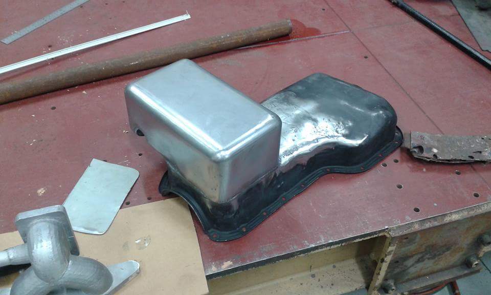
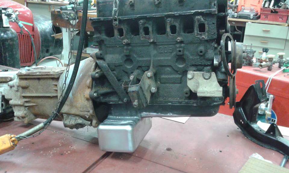
Dad modified the pinto sump to clear the escort cross member because while an alloy RS2000 unit would be nice, the price is a bit excessive. I did some rough calculations to make sure it's close to the stock volume.
Note the cutout to avoid the clutch cable. Not shown in the photos is the baffle added later on.
-
3
-
-
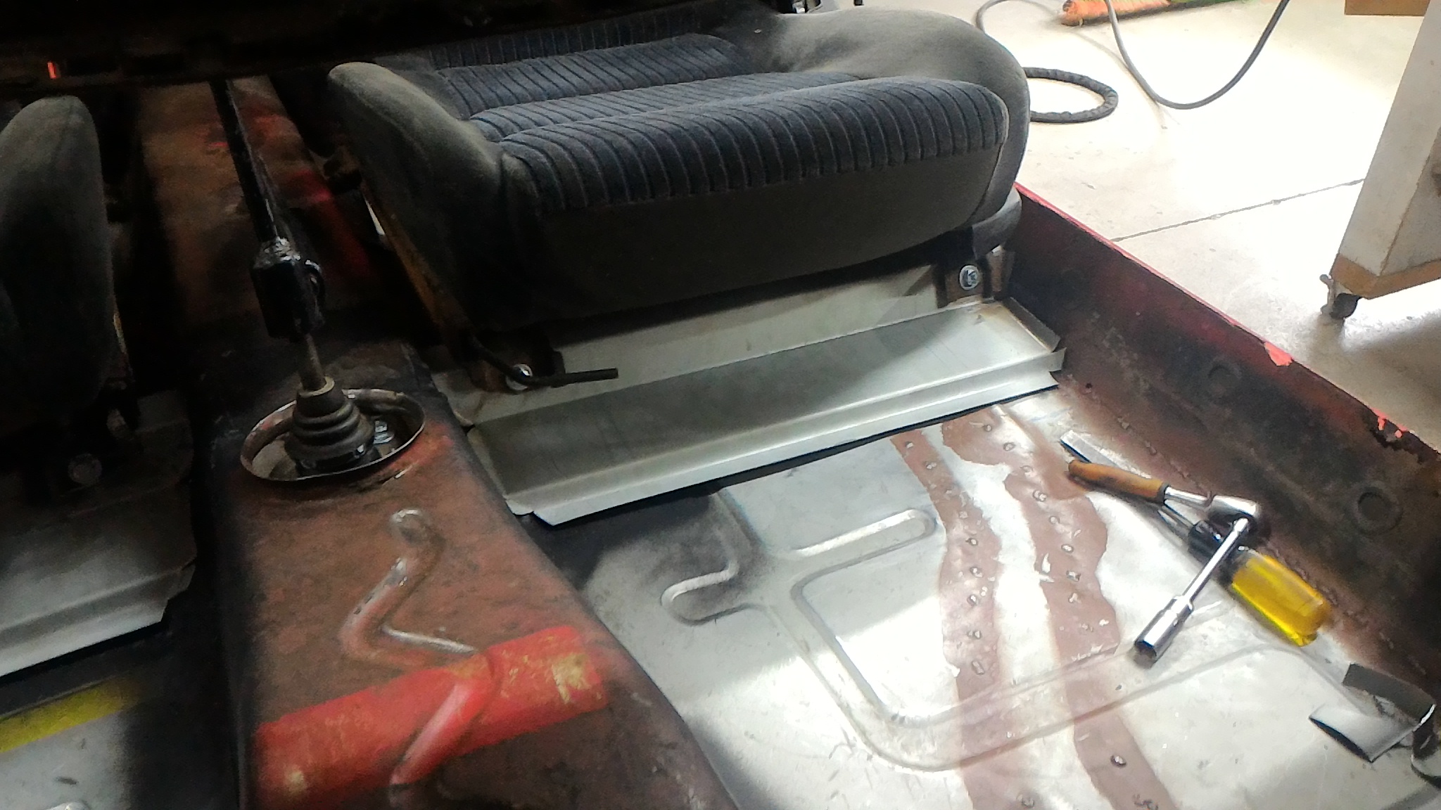
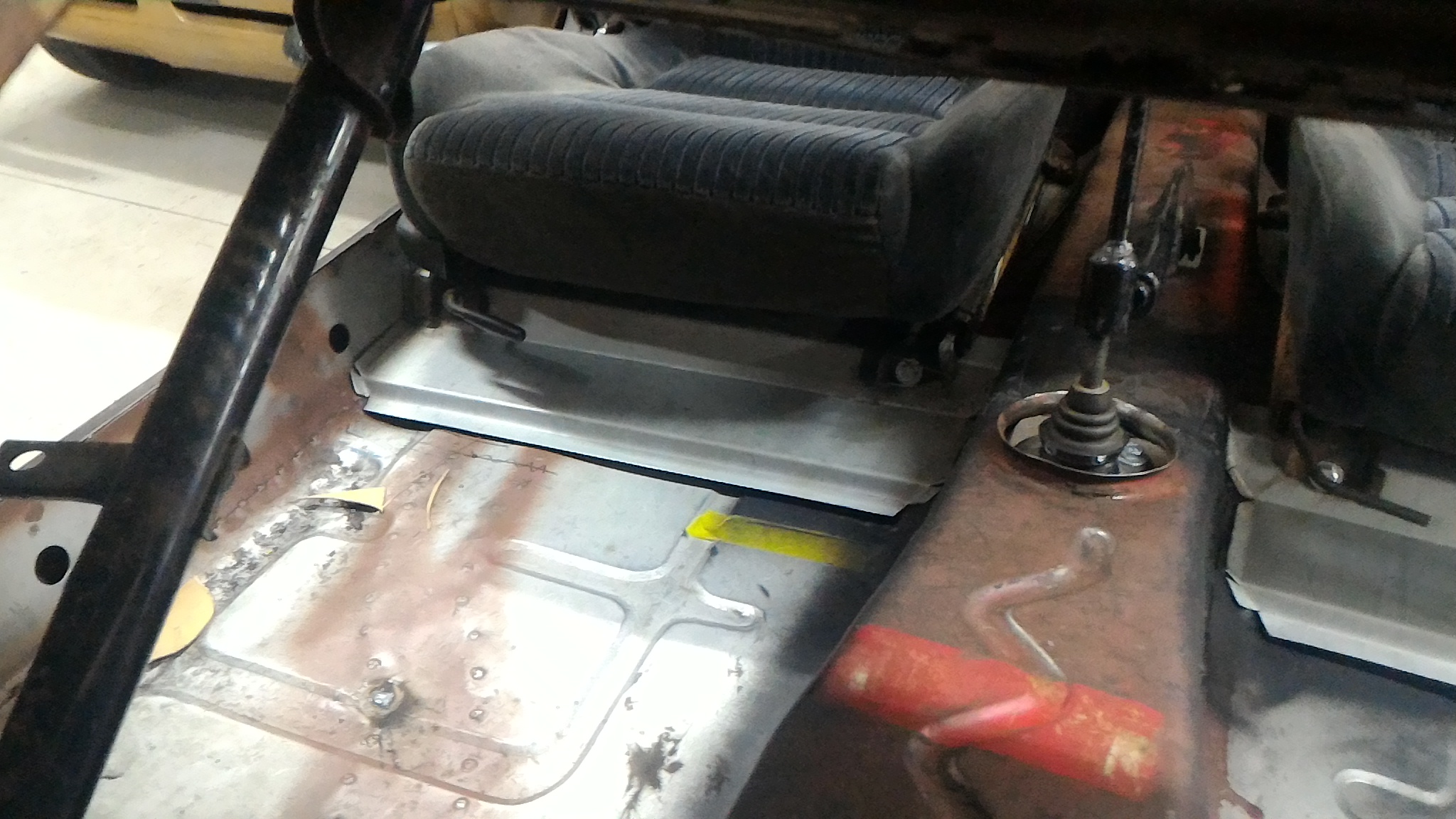
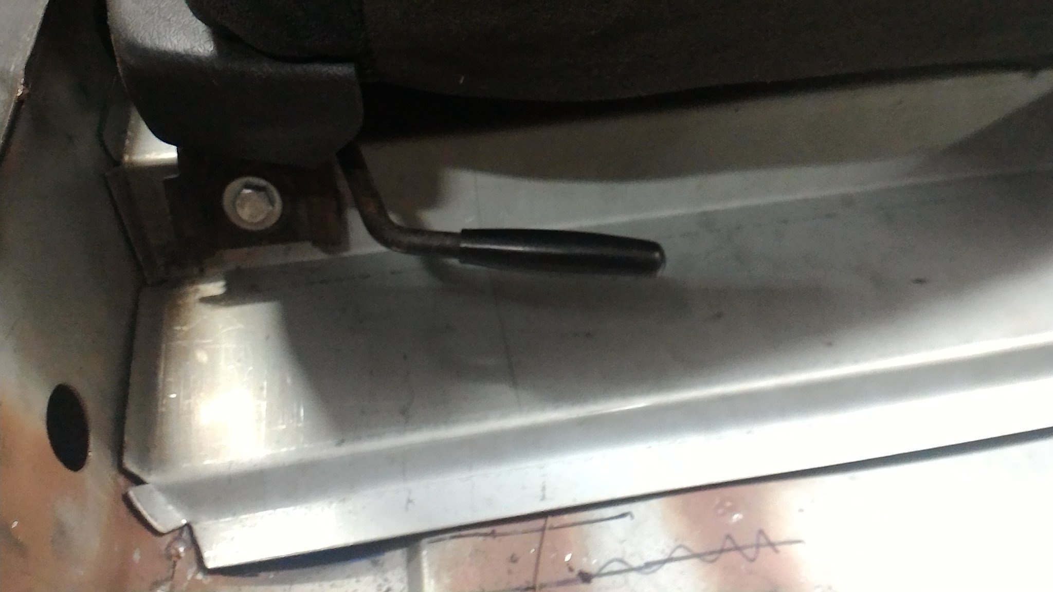
Continuing the floor themed fabrication work the next job was to make up some seat boxes to replace the ones that were torn out. I wanted them to do a couple of things. Firstly they needed to tie the tunnel brace to the sill as the stock boxes did, as well as fitting the honda seats as low as possible and still giving the full range of movement. Initially I made up a cardboard template before transferring it to steel. We folded the basic profile up on a big sheet metal brake at a local bus company's workshop before bringing it home and I fettled up the side profiles to fit the tunnel and inner sill as closely as possible. Doubler plates were drilled, tapped, and had captive nuts welded on before being plug welded to the inside of each box. While I was at it I made up the rear mounting posts as well but I can't find any photos of them right now. I might edit them in later on. Again, typical me, only the final product is shown. I'm leaving them loose at the moment until I can get a cert man to come and double check them to make sure they're up to scratch before I weld them in.
-
4
-
-
- Popular Post
- Popular Post
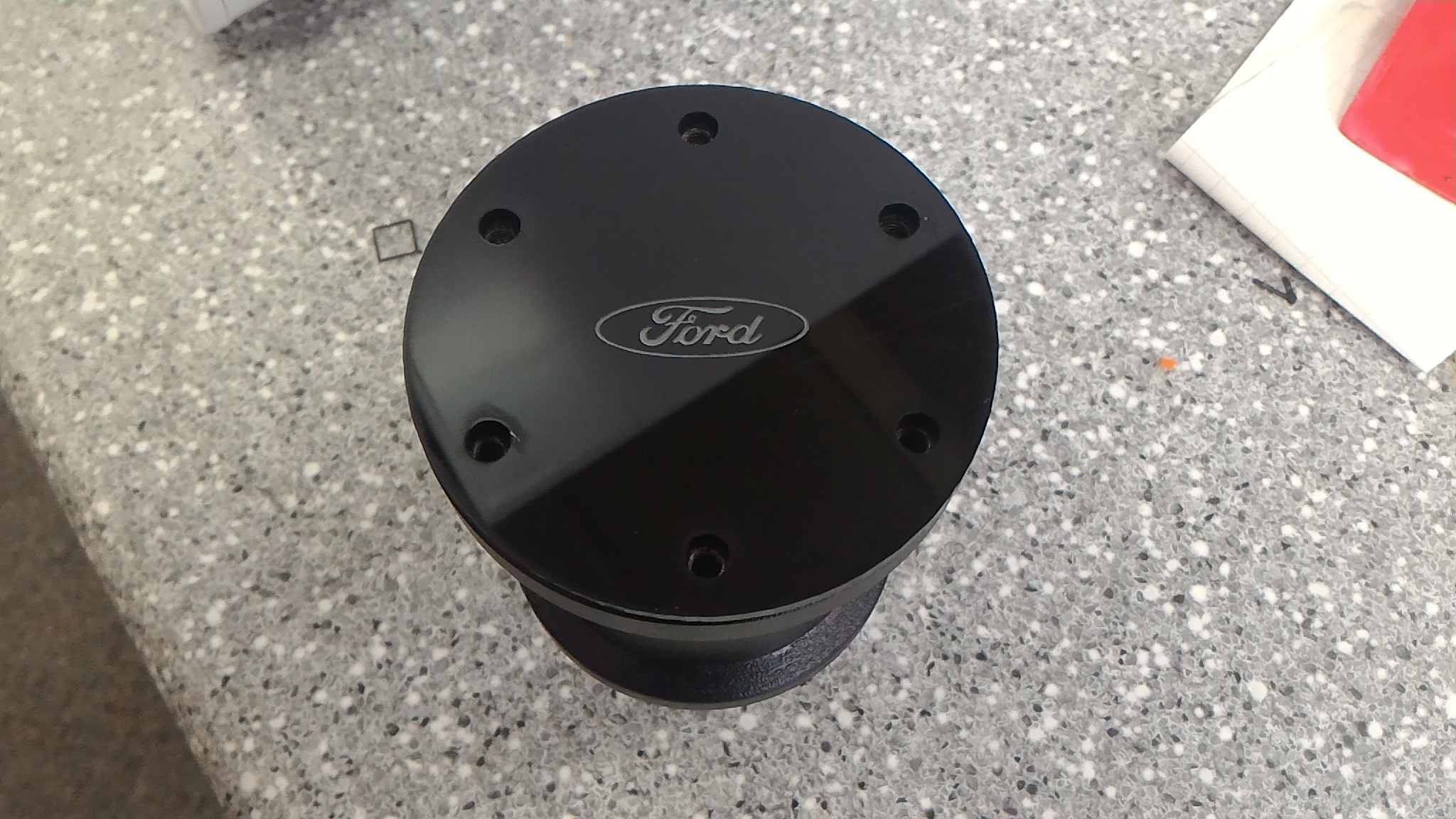
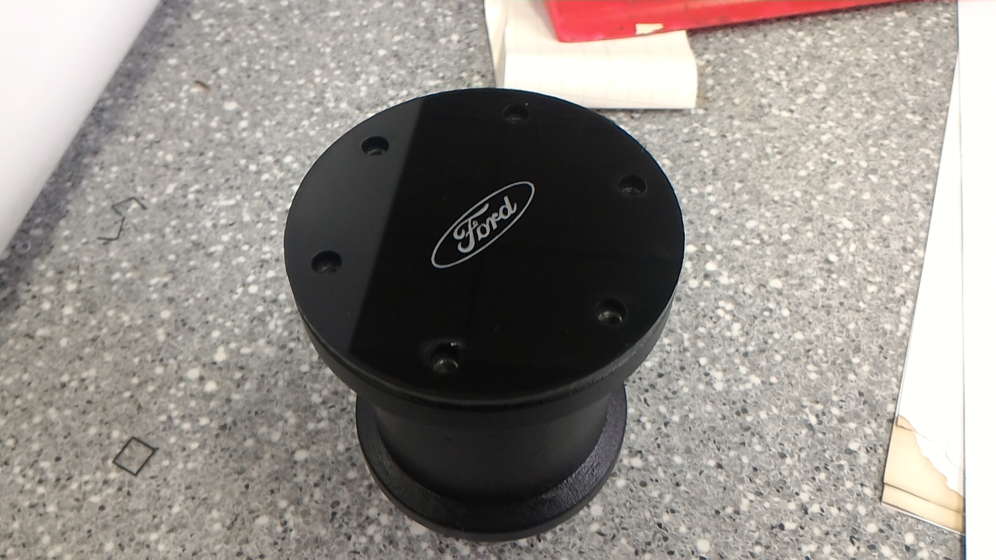
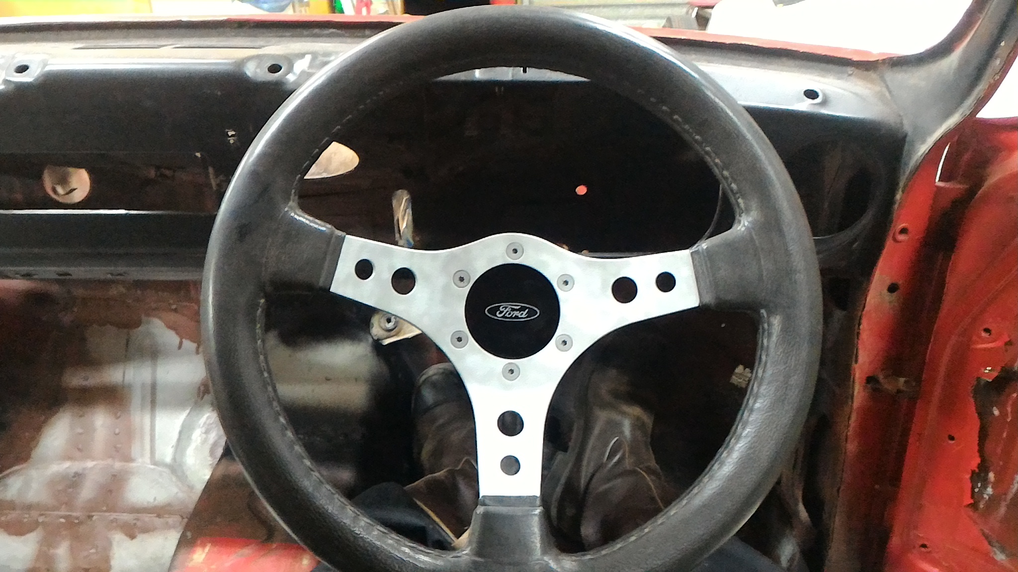
Got bored at school so I used the laser cutter to make up a nice center cap for the steering wheel I bought off a great bloke with a couple of escorts of his own. The boss and wheel had no center cap of their own and you could see right down to the main shaft nut. I though this was a nice neat solution.
-
11
-
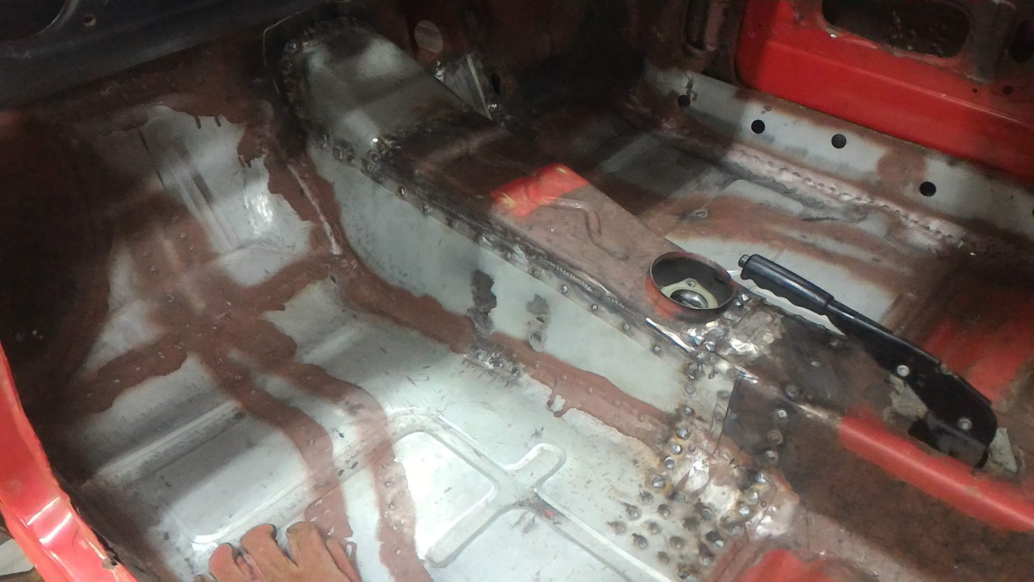
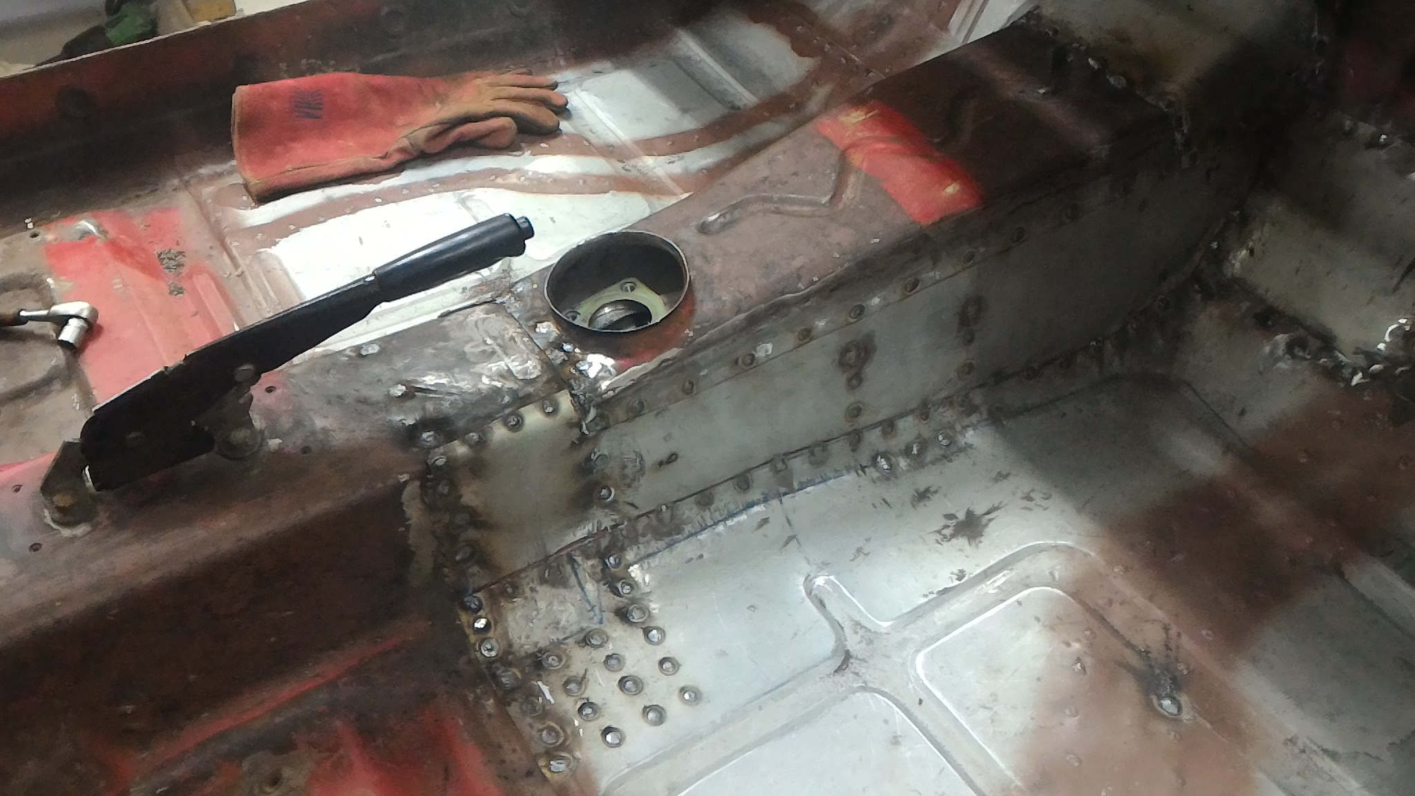
Finally we're back into the fabrication work
This time it was all my work. Again I didn't take many photos of the process unfortunately but the results got documented well.
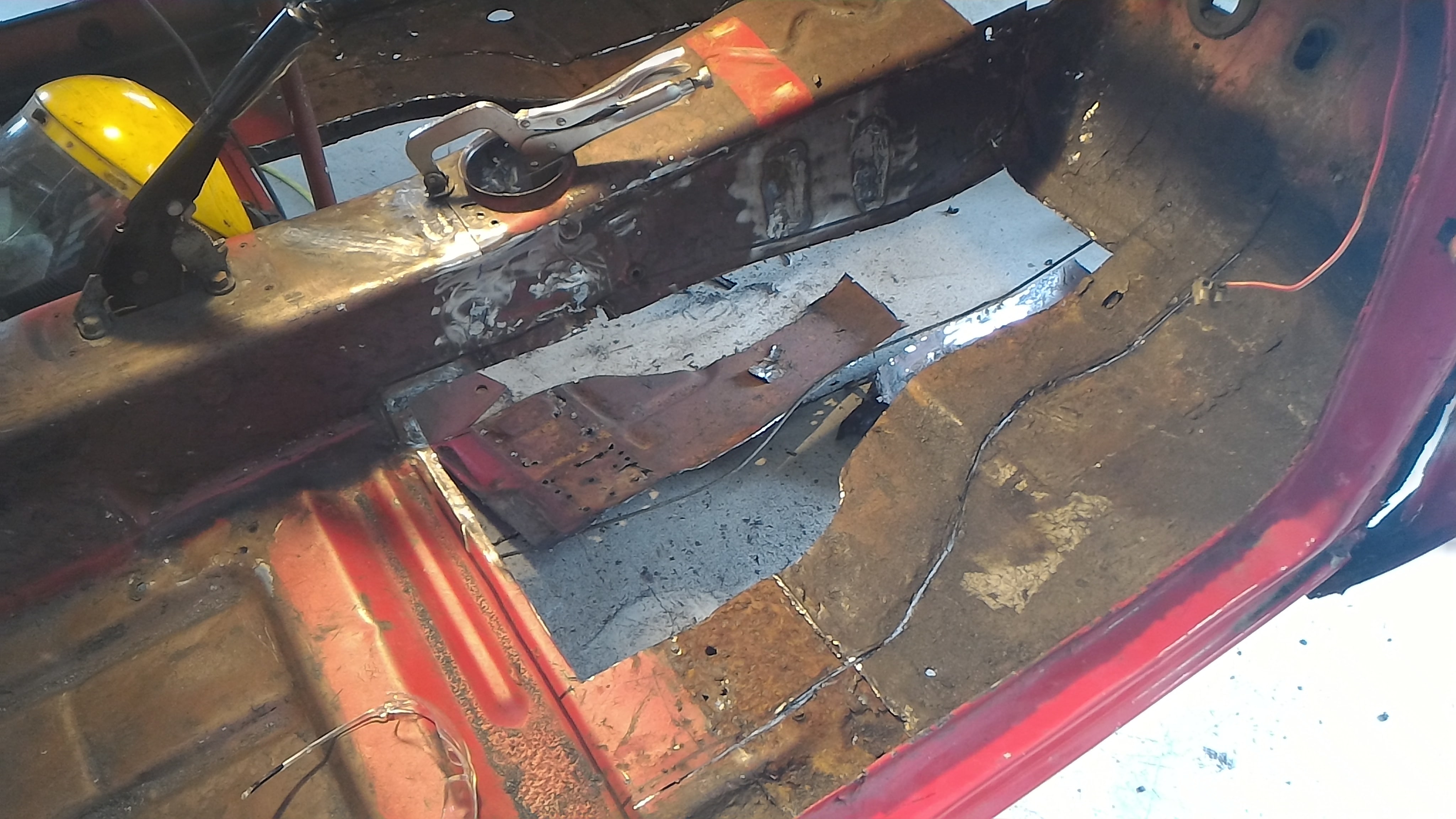
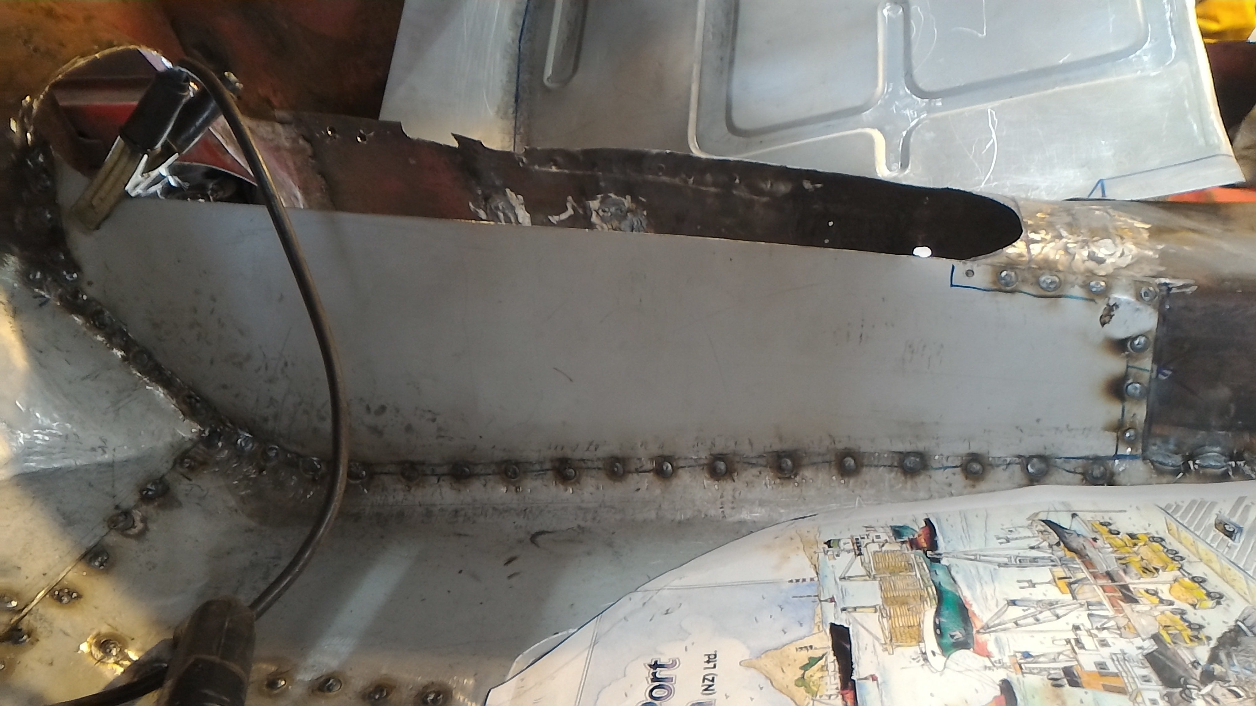
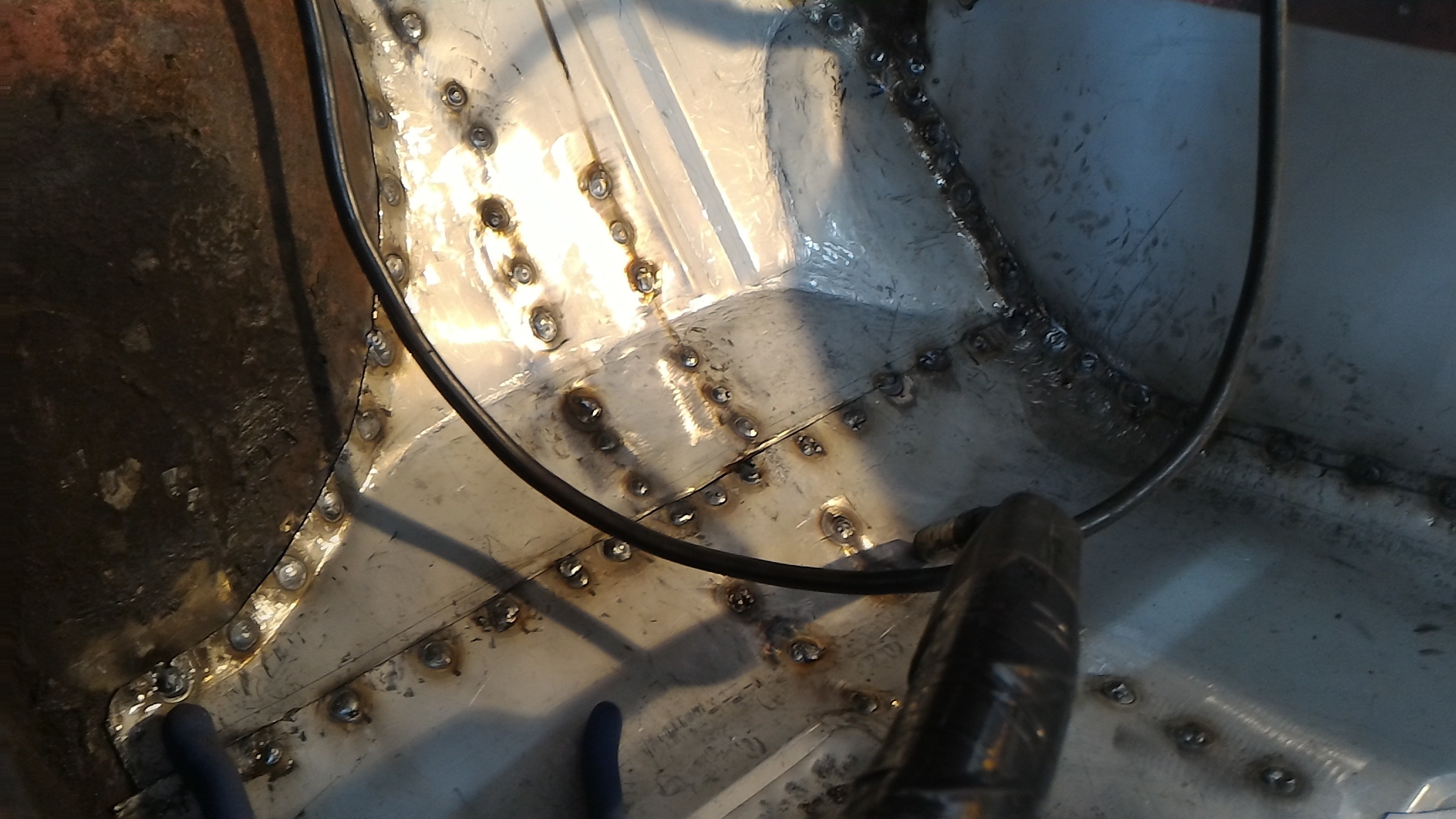
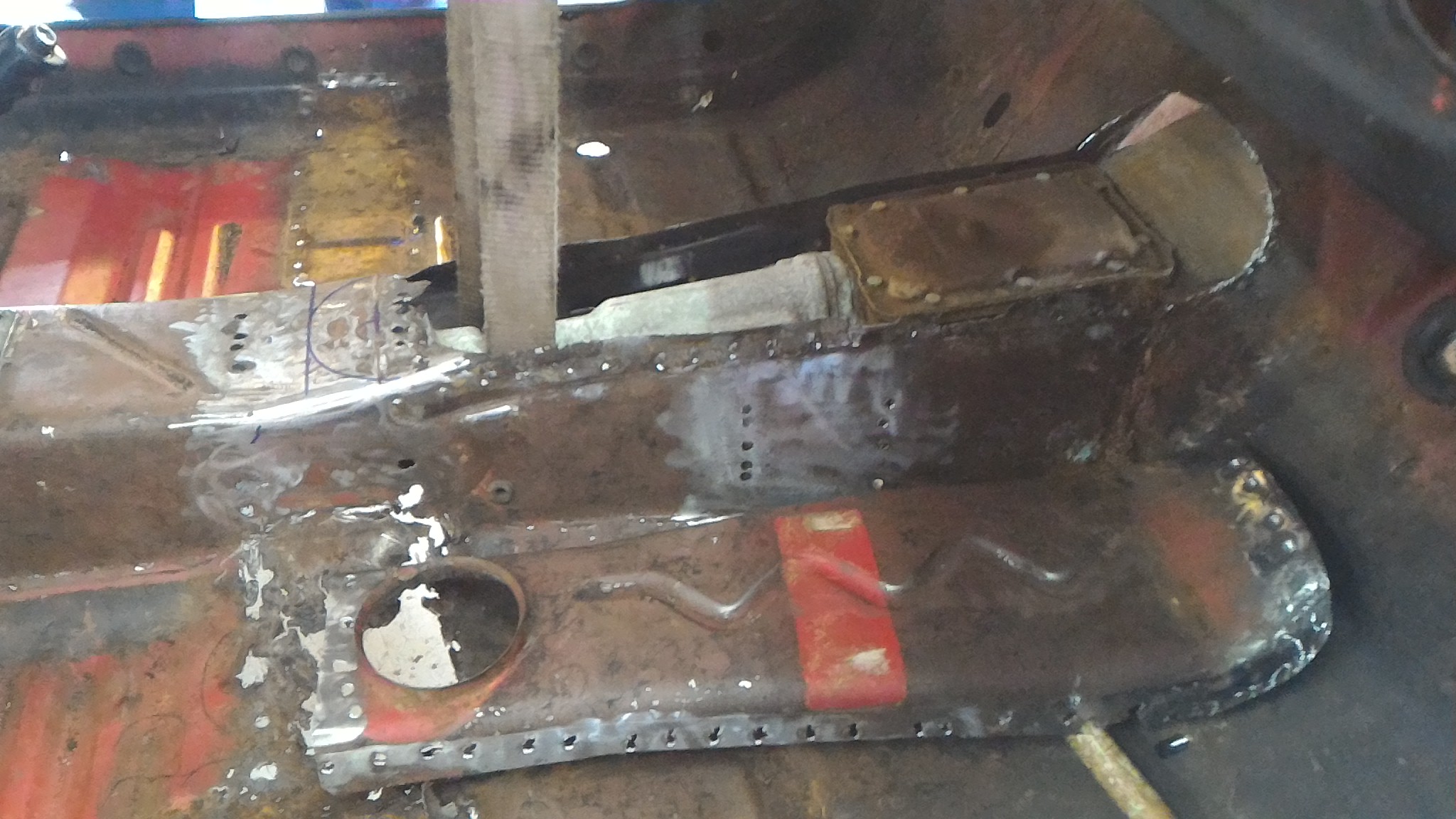
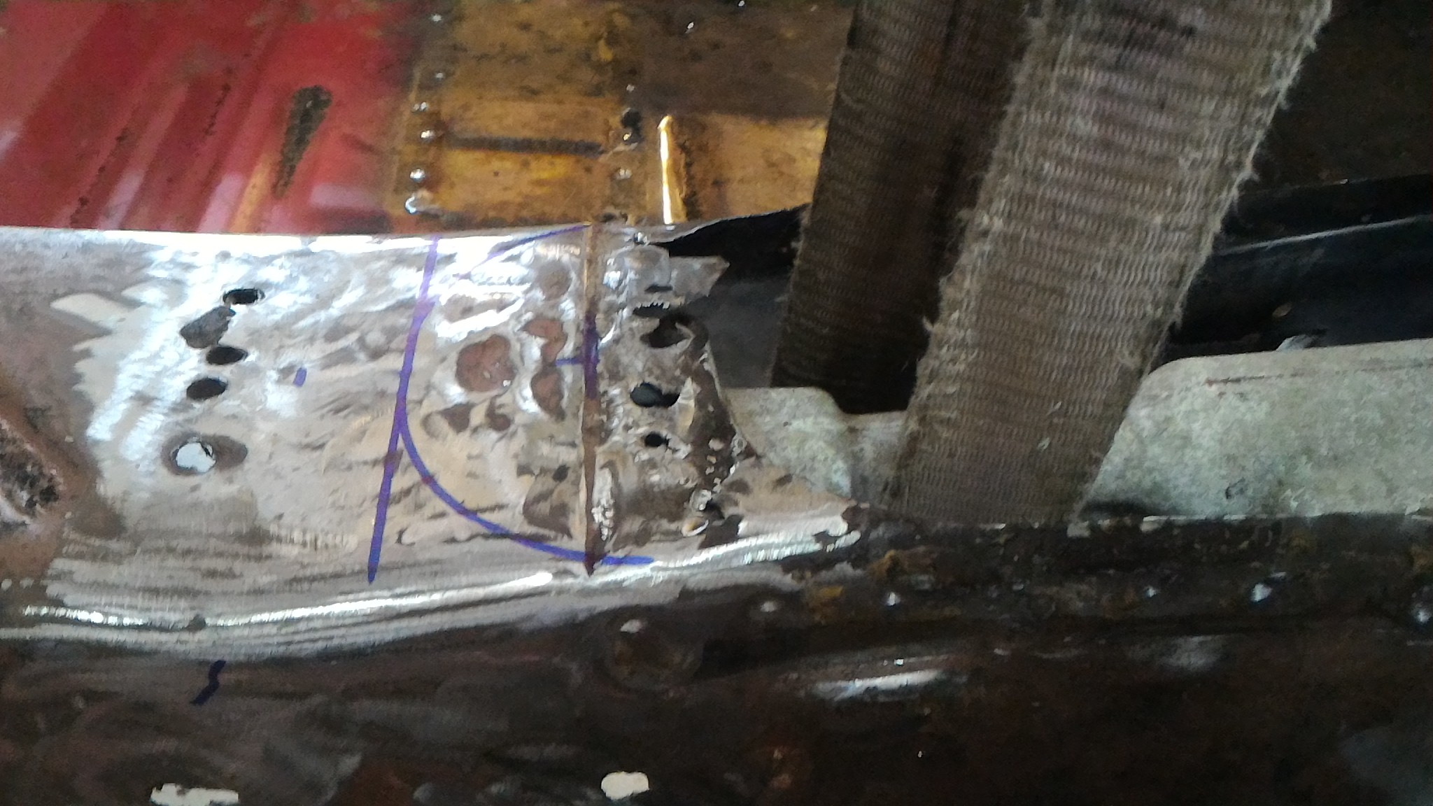
Firstly I welded in a new tunnel side for the drivers side. Then I tacked in the floor pan to the new steel, and fully plugged it in. Once that was done I replaced some steel on the edges of the tunnel top to give me some more space meat to weld it back in and then did exactly that. Then it was a matter of making a covering panel for the gap opened up at the front of the tunnel and putting that in, before modifying the tunnel brace to make it fit in the more rearward position required by the longer gearbox and welding that in too. You can see the huge number of plug welds on that brace alone which explains why this was a fair bit of work all at once.
At the same time I remounted the gearbox mounts in the new location (as you can see from the welds about halfway down the side of the tunnel) and fabbed some gearbox mount spacers to drop the box down the right amount to keep it all in the right spot.
Unfortunately this is the only photo I took of it but use your imagination. The square plates blank off the ends of the square tubing and the bits of tube are welded into the holes to form crush tubed for the bolts to pass through. Trust me when I say the came up pretty neat.
-
3
-
-
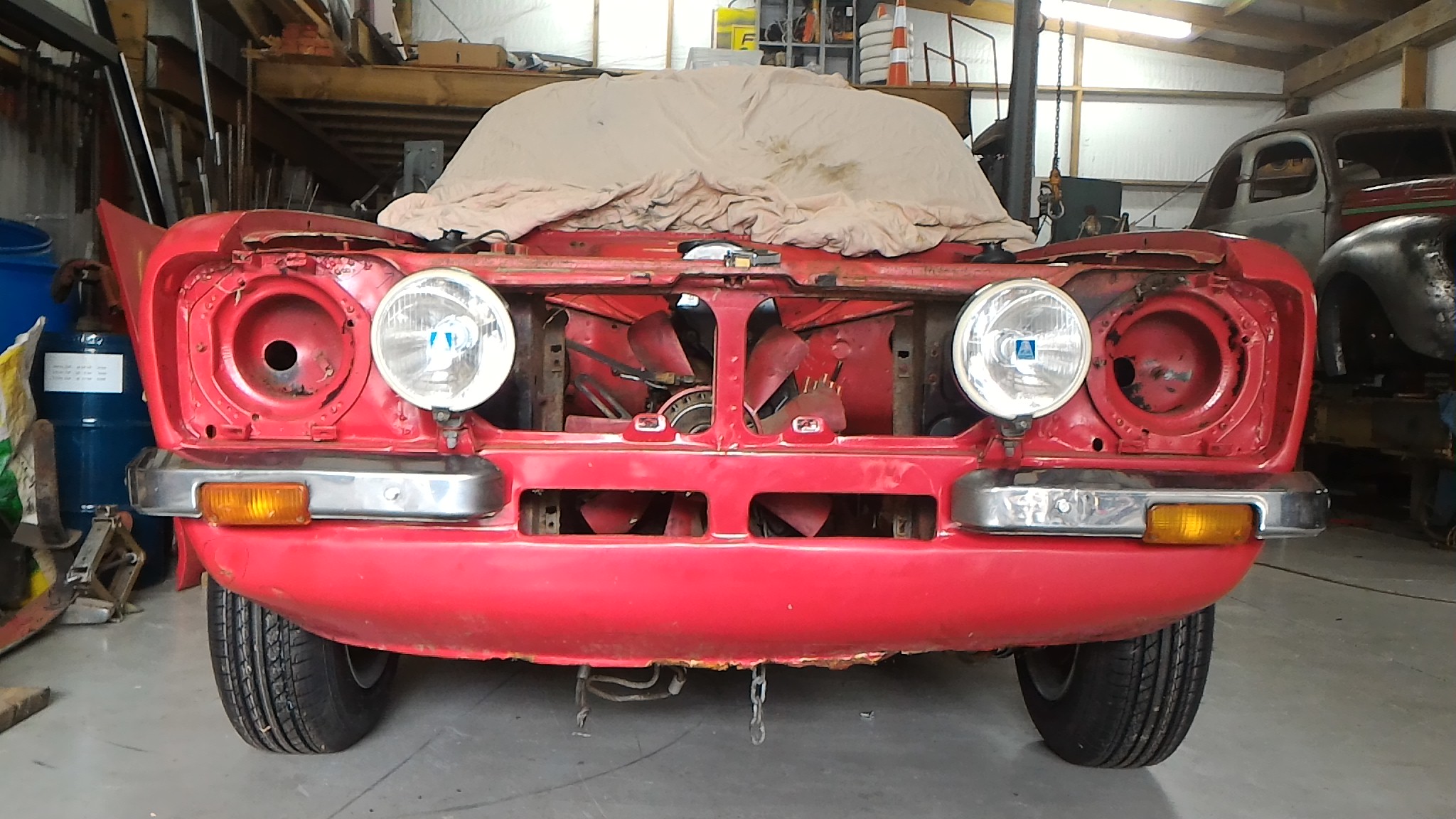
It was also about now that I splurged for my birthday and bought a brand new repro grill with the FORD lettering in the center from the UK.
Considering the amount I ended up paying for it I wasn't too happy with the quality of the finish (the silver "paint" is just very poorly cut decals) but it should come up pretty good with a lick of paint. I much prefer this style of grill but they're rare as rocking horse shit to find and the guys that do have them never want to sell so a brand new one it had to be.
-
2
-
-
About now I decided that since I didn't know the history of the engine I had been given or the condititon of any of the internal components I would get a second pinto that I could drop straight into the hole once everything else was ready for it.
So here it is. $350 later I have a "running" generic stock pinto motor with almost everything I would need to get it running. The other advantage of this is that now I can throw an engine in it to get it running while I save up to pay for the machining and parts to make a really hot little 2L with a big valve ported head, possibly oversized pistons, etc etc out of the more stout 205 block pinto I was given in the first place.
-
1
-
-
In other news, my manifold came back!
It's much shinier now than when it left. Here it is in the jig we made up to hold it in the mill in the school workshop. Not to bad for a quick 30 minute jobbie.
And this is it after starting to milling it flat. The cutter is typical school quality after being used by a bunch a 13 year olds (that is to say it's pretty fucked) so it wasn't the best finish. That said it's nothing that can't be cleaned up on a surface plate with some fine grit sand paper.
Unfortunately the mill wasn't big enough so it was put on hold for a while until I could get access to a bigger mill at a local engineering shop. So for now that's extent of the manifold story.
-
6
-
-
50 minutes ago, Adoom said:
I have one of these. Makes spot weld drilling easyish. I've drilled maybe 30 spot welds and I'm still using the first side of the cutter dealie. You get 11 cutters that you can use both sides of, so 22...
You need to center punch or drill a little dimple, or the drill just fucks off and makes scratches. Start slow and don't push hard till it's started cutting, or, the drill just grabs and fucks off.
Yeah I figured out the center punch method but this was a couple years ago now. I've since bought a proper bit and man the difference is fantastic. Unzips panels like a dream.
-
2
-
-
The inner sill was replaced at the same time. It was all fully welded in the end but I can't find any photos.
At the same time we pulled the heater bubble off and repaired the usual rust spot with another repro panel top along with a custom bottom patch.
Then it was time to put it back on the trailer and haul the whole lot home.
-
3
-
-
To make the most of the time I had off we put the car on a trailer and dragged it to yet another of dad's friend's. He's a retired panel beater who kindly offered to do some more advanced panel replacement stuff that dad didn't want to do. Even more generously he was happy to let me hang around during the day and learn. So over the course of a few days he cut out the rotten driver's side sill ready to be replaced with a repro panel from palmside. He made the comment on how the shell didn't move an inch after losing the whole sill, even with no extra bracing put in.
Once it was cut out the new panel was tacked in
-
3
-
-
Lacking a proper spot weld drill as well as much knowledge of how to properly split spot welds, I decided to attack the driver's side guard. It had some decent rust along the back bottom edge and at the A-pillar join so it needed to come off. Here is the results of my ignorance.
Once that was split, not much really happened until I got a couple of weeks off over the school holidays.
-
3
-
-
- Popular Post
- Popular Post
The next stage was the beginning of a very interesting and ultimately expensive experiment. My dad has owned a mk1 escort for close to 20 years (it could probably have a thread of its own). It's running a 1600 with a twin 28/36 downdraft weber setup on a custom manifold he made up out of exhaust tubing. The carbs run rich as all hell due to never being tuned properly and the but if one carb is good then two's gotta be better right? Not to mention that sweet induction noise of the downdrafts.
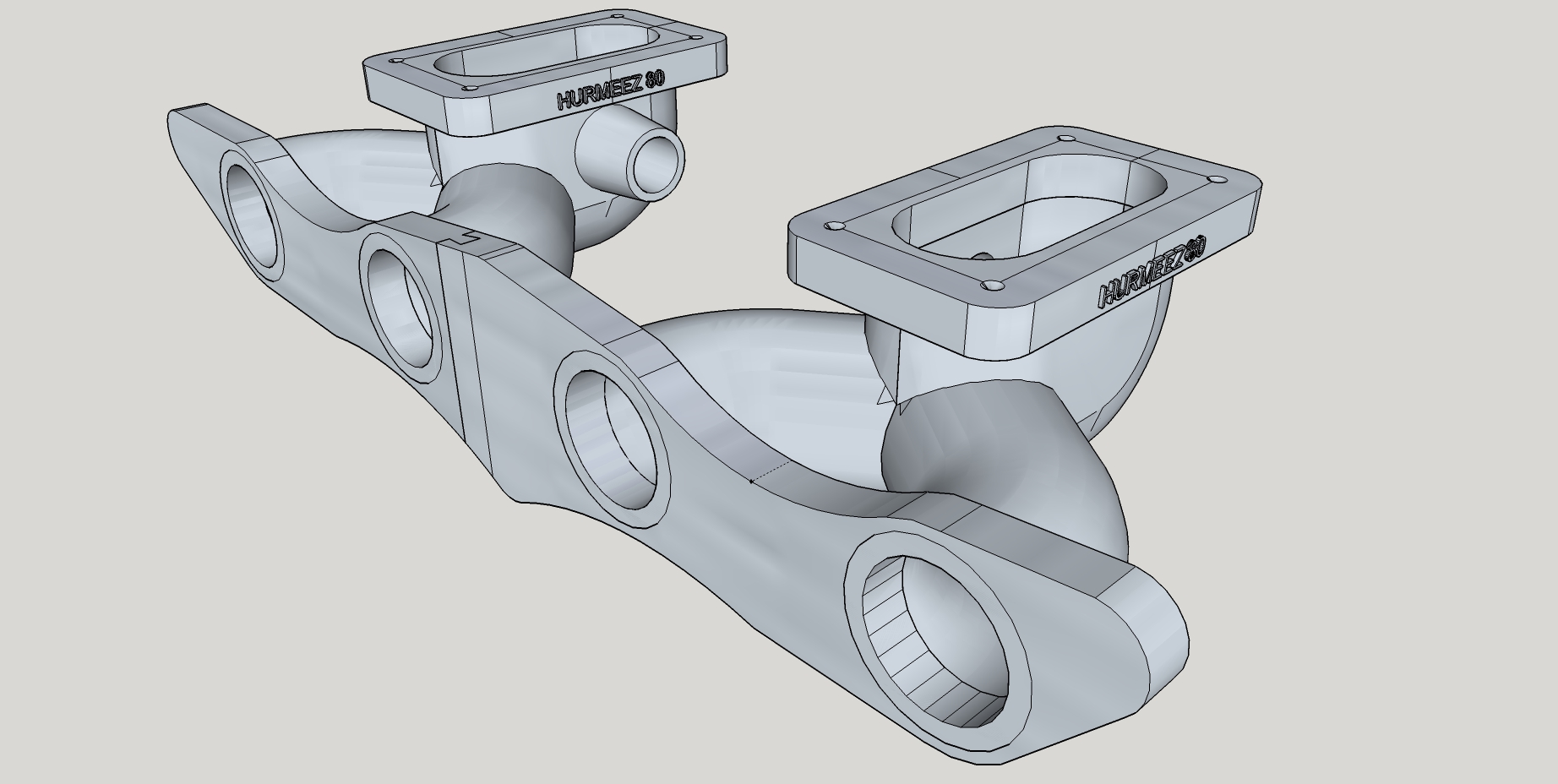
So he suggested that I do a similar setup for the pinto. Downdrafts are much cheaper and easier to source that sideys after all. So I decided that I'd run the slightly larger 32/36 webers on a manifold with a similar design. But in cast aluminium.
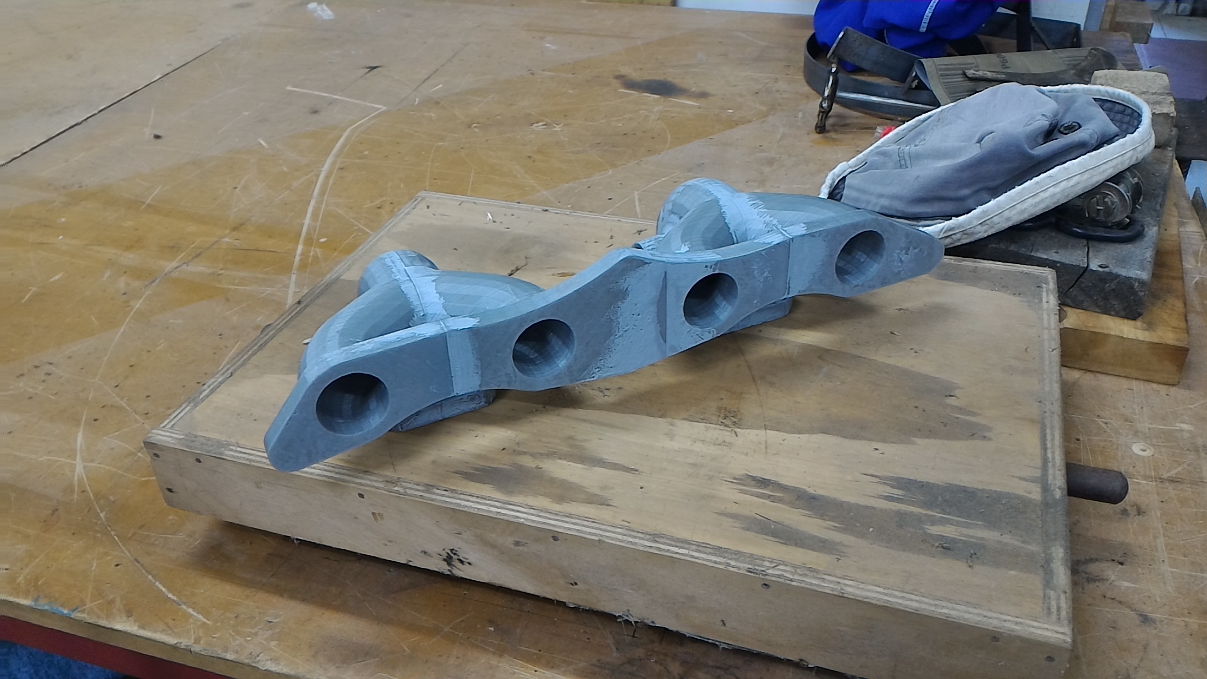
We'd read about using 3D printers to make blanks for lost wax casting metal components and as an experiment we decided to give it a go. So I set to designing a manifold on sketchup over the course of many days. Turned out something like this.
Then after finally wrapping my head around how to get it all to work I sent the file to a classmate and he printed it out on his homemade 3D printer. I had to split it into four separate parts to fit it in the printer then glued them all together and put some model filler putty to smooth it all out. The design almost exactly copies the exhaust tubing version my dad made. I didn't really take into account runner length or plenum volume or anything which in hindsight I do regret a little but at the time I had no idea of the significance of any of these things and was just aiming to make a copy of my dad's design. Then it was packaged up and sent to a casting shop in Christchurch somewhere (the name escapes me) and promptly forgotten about for a couple of weeks while it was cast. Meanwhile, more stripping down was taking place on the car...
-
11
-
Just now, Mr Vapour said:
nice work.
Im thinking that your dad has done this before.
how did you do the floor? HAve you got a bead roller?
Yeah we traced the outline of the swages onto the steel and rolled it up on a bead roller. He's very good at what he does. This is his car https://www.jalopyjournal.com/forum/threads/kiwi-made-1927-t-lakes-modified-journey-to-the-end-of-the-road.685236/
-
2
-
-
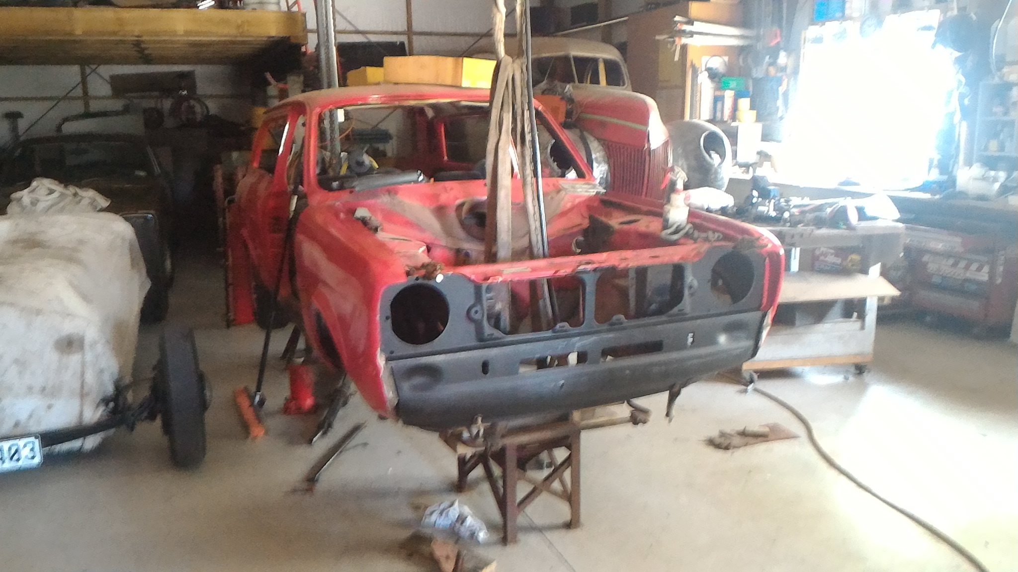
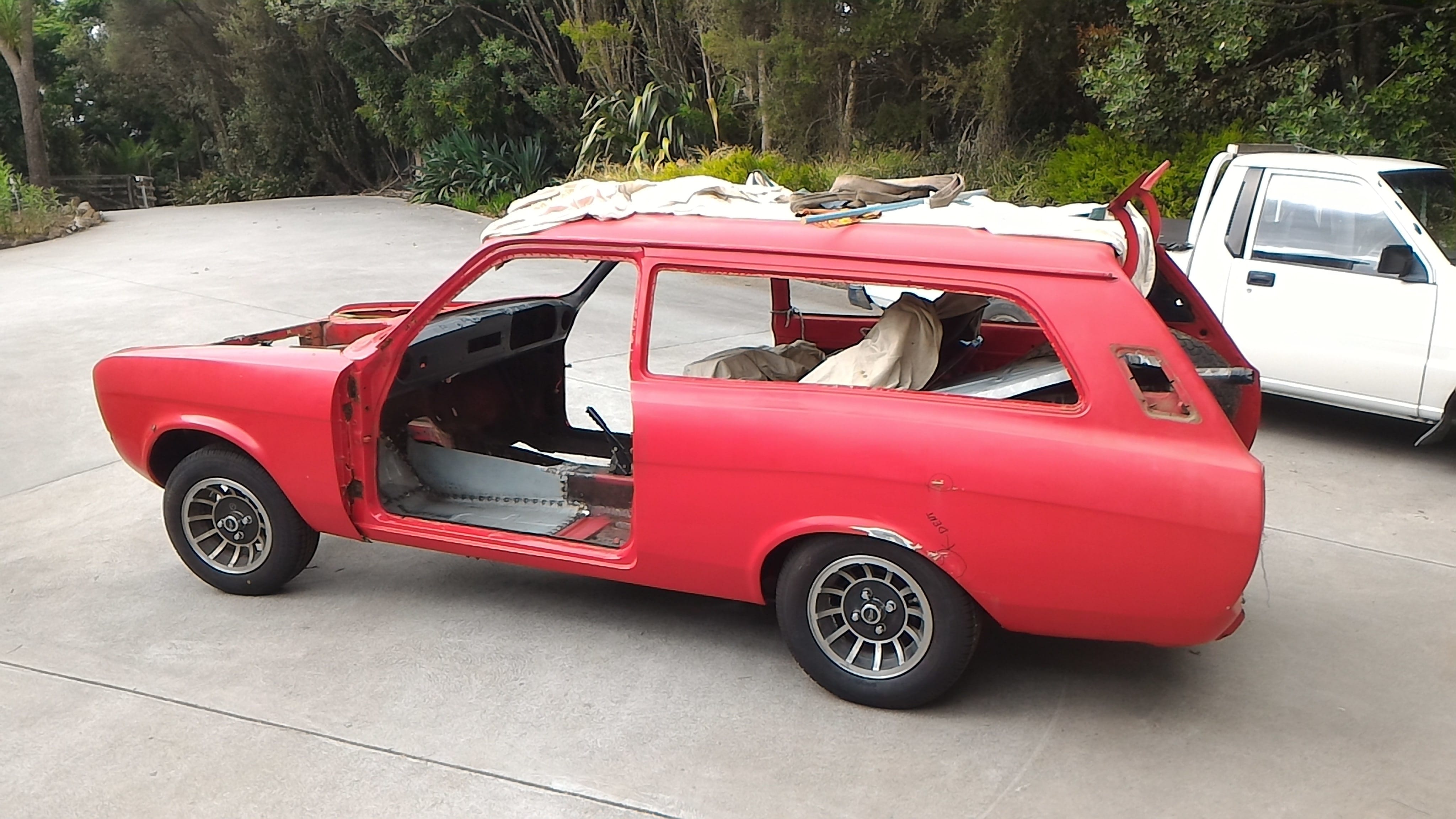
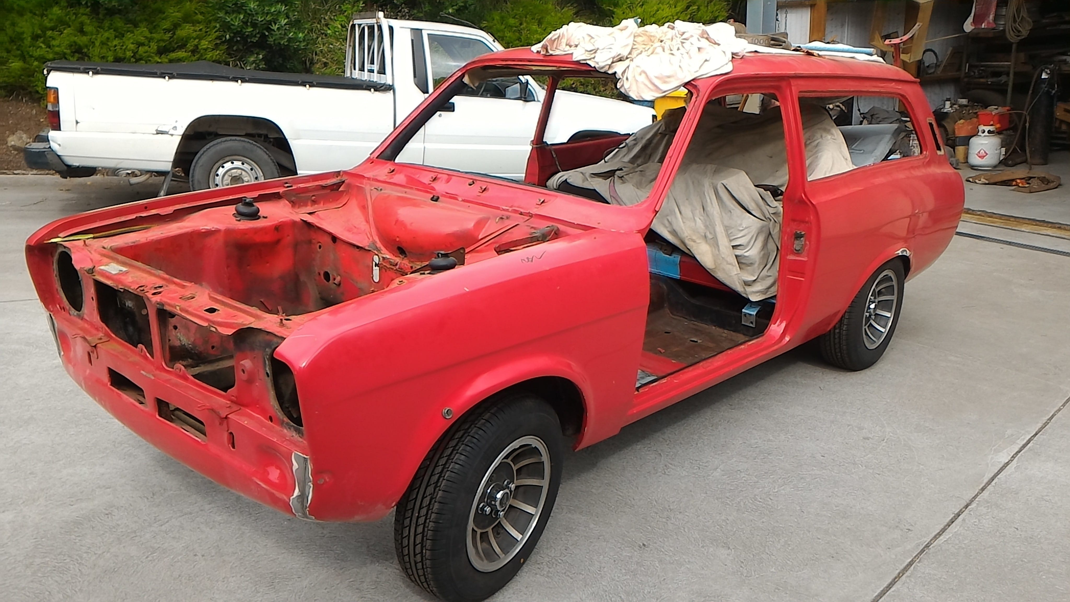
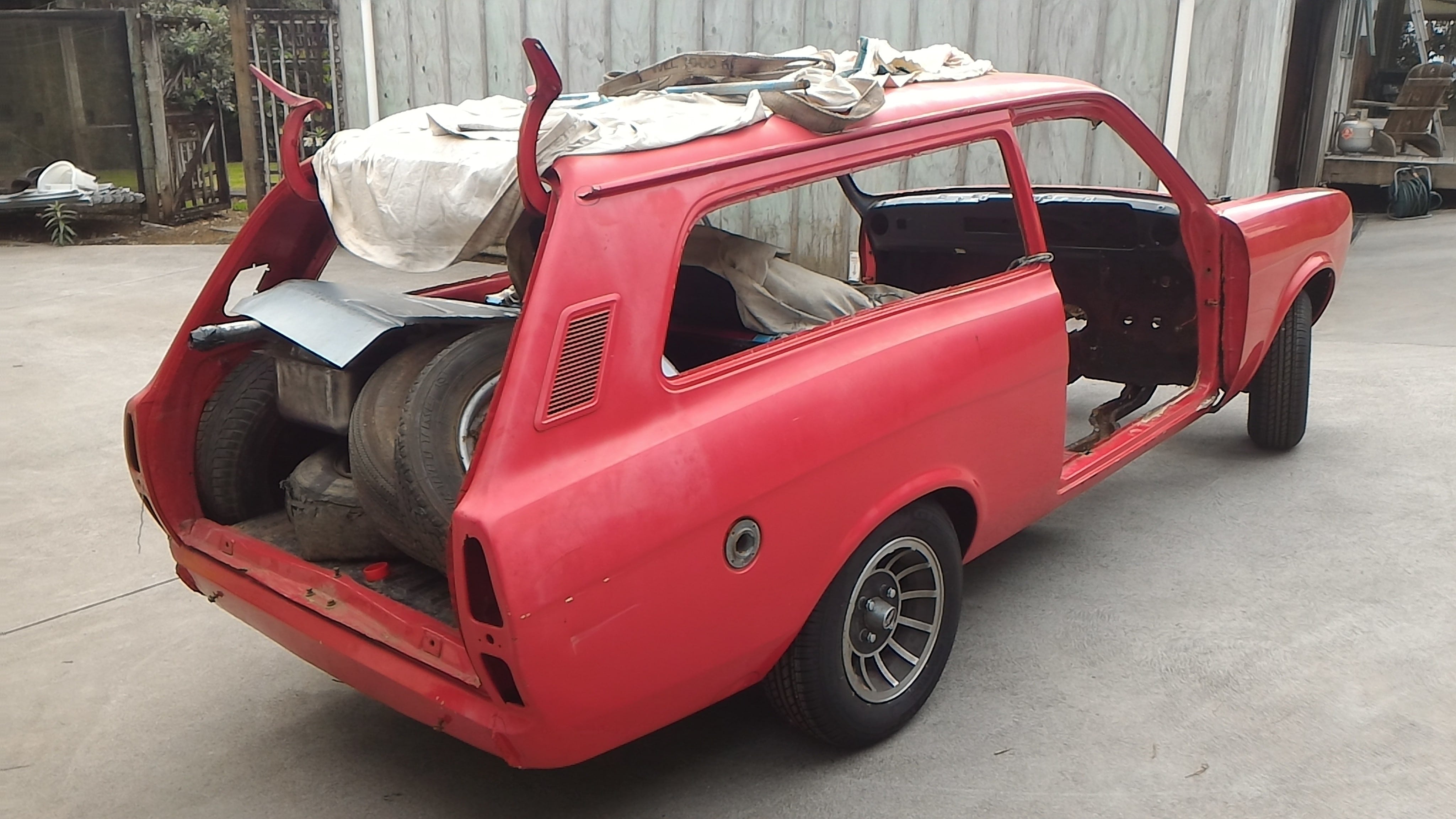
Then we rolled it out of the shed (probably to get it out of the way of something or other, I forget) and took some photos of it in the sunlight. It sits a bloody long way up in the front when there's no weight in the engine bay.
Flintstones power plant on show.
I'm really digging the cheviot turbos. They look sweet in the sunlight.
-
5
-
-
Now was the point where it was decided that the pinto was simply too modern and complicated for what we wanted. We needed something simpler, more prehistoric. So Flintstones power it is!
Saves a bunch of headaches worrying about complicated stuff like fuel and electrics and so forth this way.
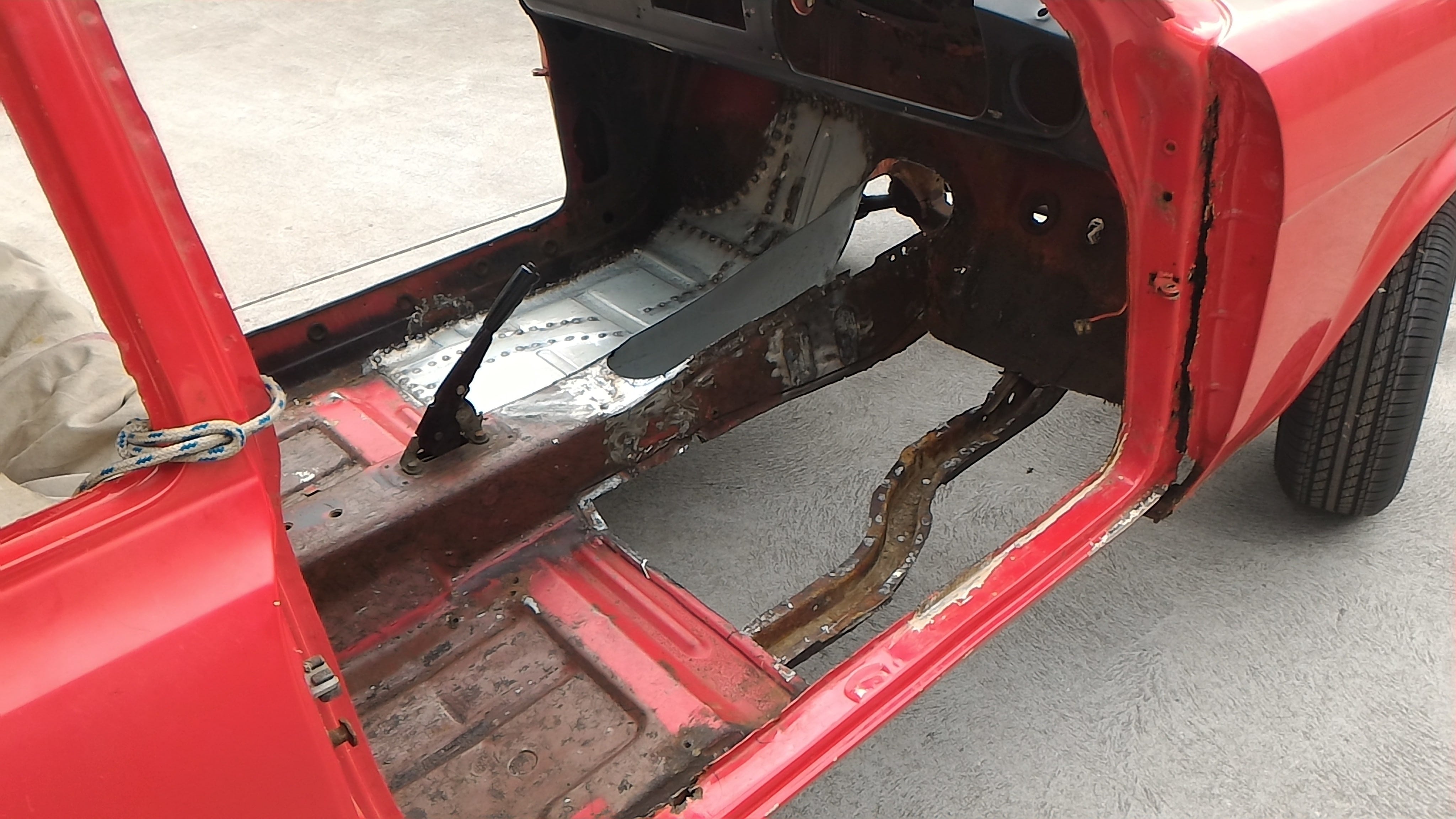
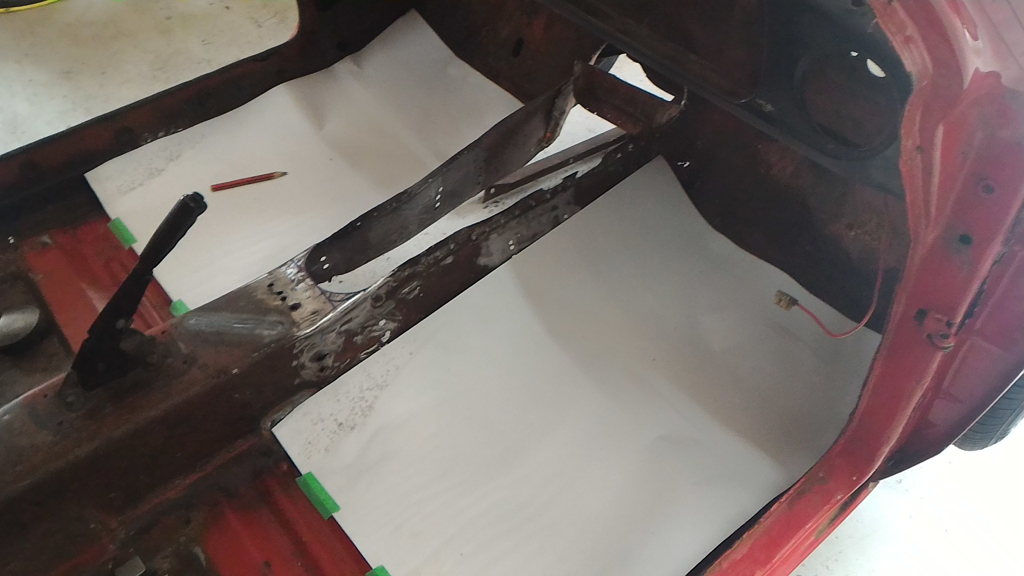
Before we cut the floors out we lay some poster paper down on the floors and made up some templates to then be transferred to 1mm sheet steel to make up the new floor pans.
Then after my dumbass forgets to take any photos of the process, you have two floorpans with close to stock swage locations. Then it's a simple job of filling up ten billion plug welds and viola, one floor pan welded in.
You'll notice the side of the tunnel was cut out and replaced as well. This wasn't the original plan but after taking out the gearbox mounts and seat boxes it was in such a state that replacing the lot was much easier than trying to fill each hole individually. It also affords the peace of mind of knowing there's some decent gauge steel in the car rather than ford's paper mache.
A massive thanks to my dad for all this. It was a while before I had the confidence to start doing this sort of stuff myself.
-
5
-
-
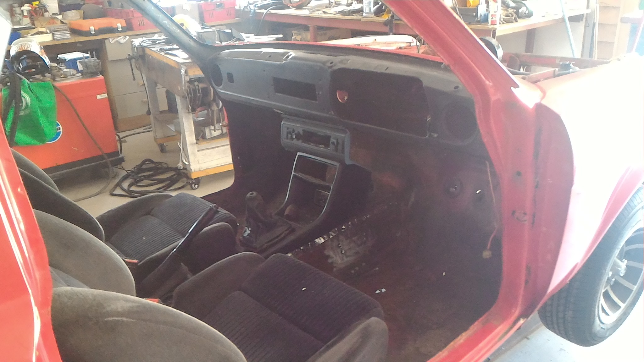
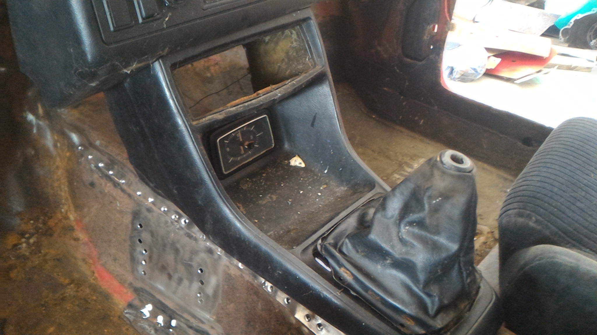
The eagle eyed among you may have noticed some holes drilled in the trans tunnel under the center console in the last post. They foreshadow the next step on the journey.
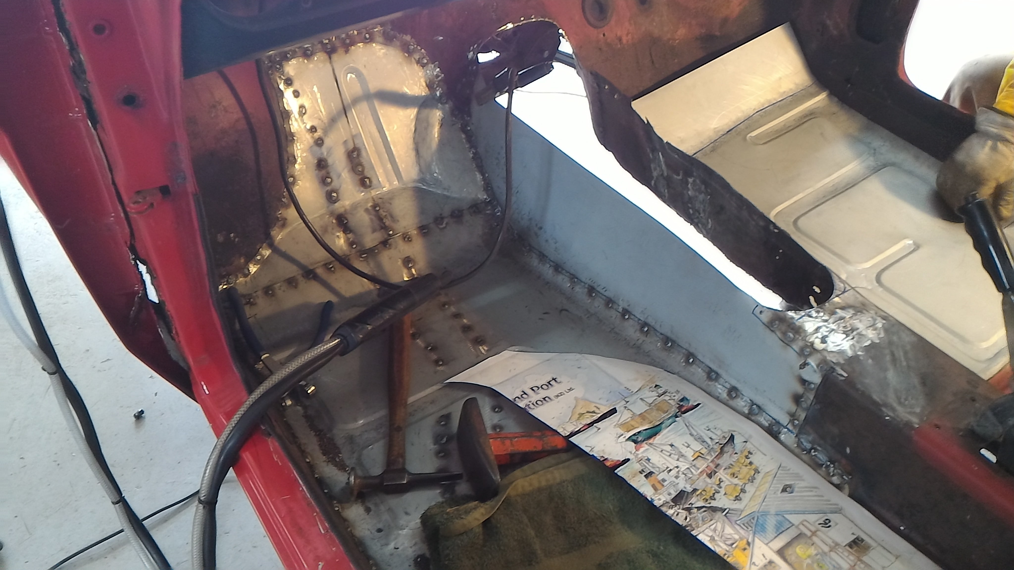
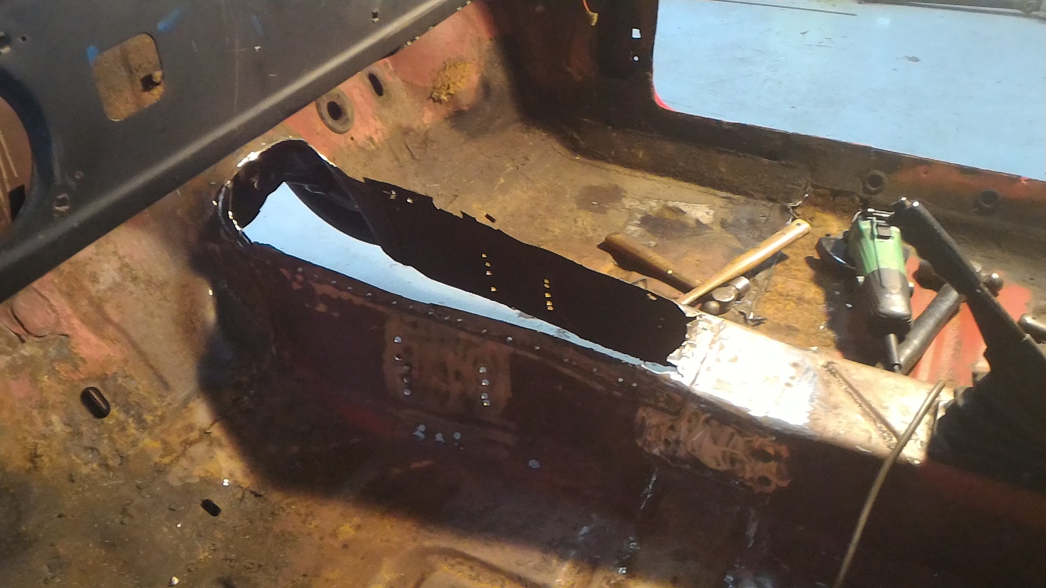
The next thing we wanted to do was get the type 9 in the hole to see how things were going to line up and how much fab work was going to be necessary. So that meant making a bloody great hole in my car!!
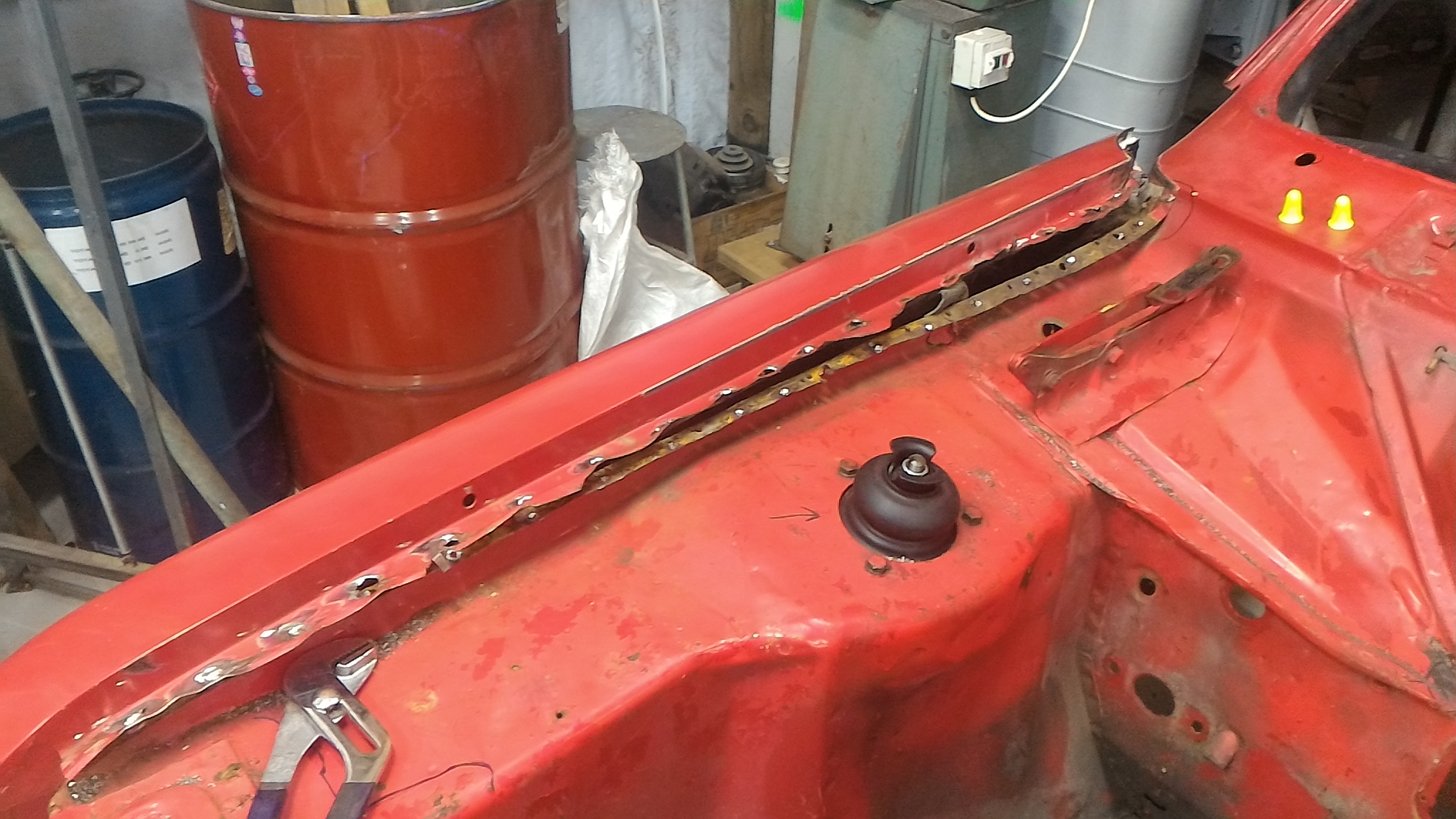
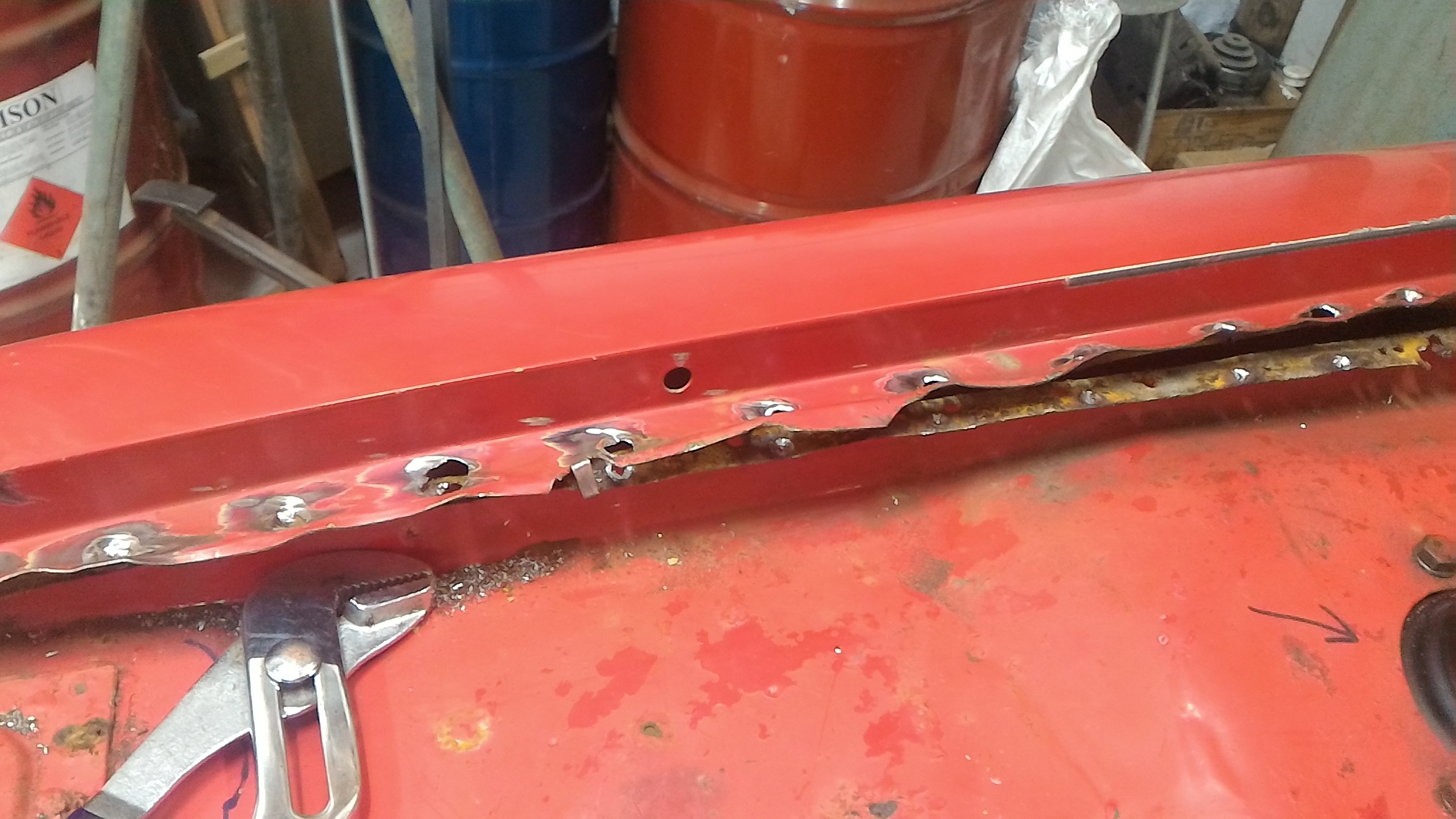
As you can see from all the holes, we carefully located all the spot welds and delicately drilled them out before gingerly hacking the firewall to pieces with a dodgy grinding disk. The seat boxes were pulled out at the same time revealing more rust holes.
By doing it this way the plan was to move the top of the tunnel rearward to retain the stock swages and shape. Then a simple patch was to be made to cover up the gaping hole opened up at the front of the tunnel. Simples. Also the gearbox mounts were removed in a similar fashion to be relocated to fit the type 9 at the same time.
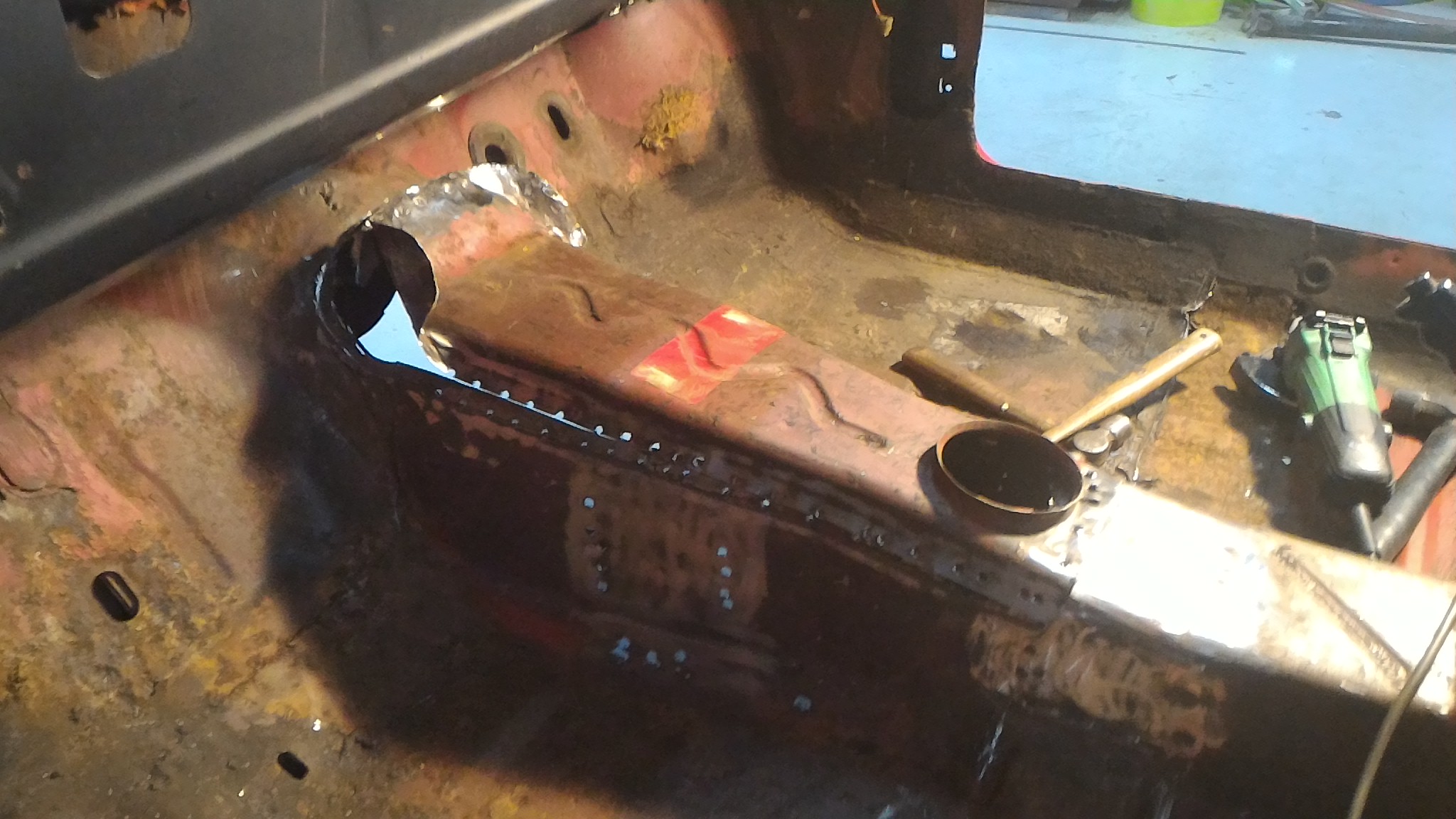
Here we've hung the box off the hoist to put it within cooee of the right spot. The rust holes that were under the seat box are clear here as well.
Then it was a simple task of marking up the new shape and trimming the paper thin factory ford steel with tin snips.
But that's enough excitement for tonight. More tomorrow.
-
6
-
-
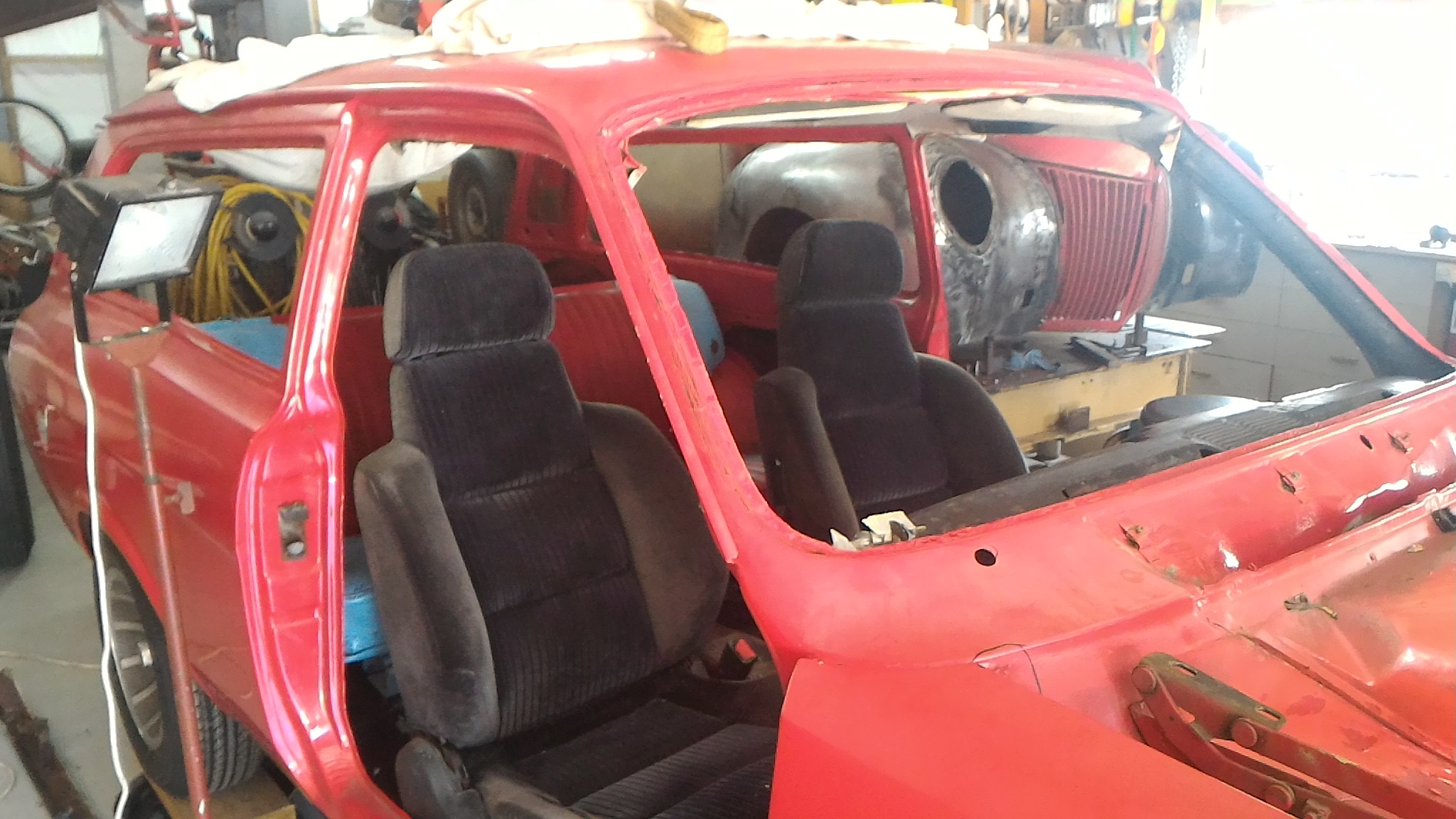
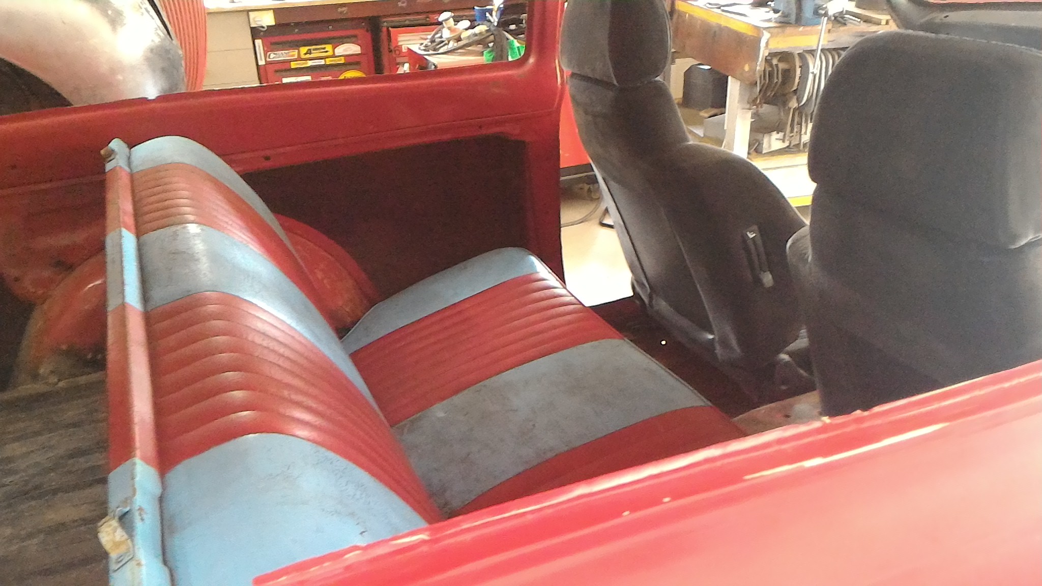
The joys of having a dad with car obsessed mates...
A couple of things happened in the same day on this day. Firstly a mate of dad's had a couple of seats he was planning to put in a T-bucket he was building up. However, in his opinion the small amount of wear on some of the upholstery meant they were useless and he didn't want them anymore. Not exactly sound logic in my opinion but there you are... his loss, my gain.Another thing I can add to the free component list.
As you can see they're not the prettiest seats in the world but at the end of the day they're free and I think I have a plan to sort out the ugliness. I did a quick bit of research and apparently they're out of a 1990ish honda prelude so at the end of the day I can make mounts to fit these and if I want to I can fit bucket seats designed to fit a prelude if I want. Despite their looks, they are very comfortable with lumbar, tilt, and lateral support adjustment along with the bonus that they have the passenger operated tilt lever so the guys in the back seat can get out easy.
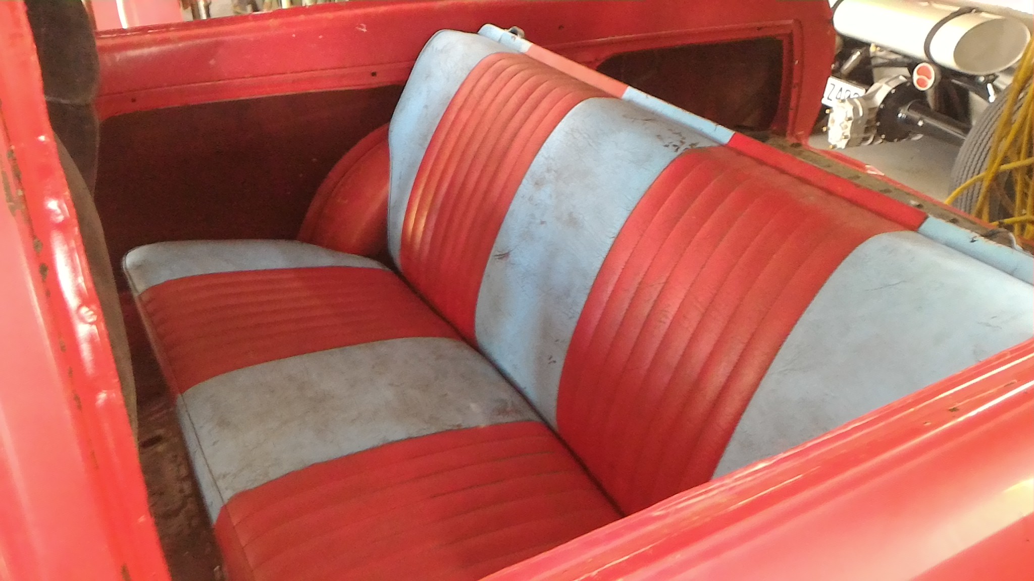
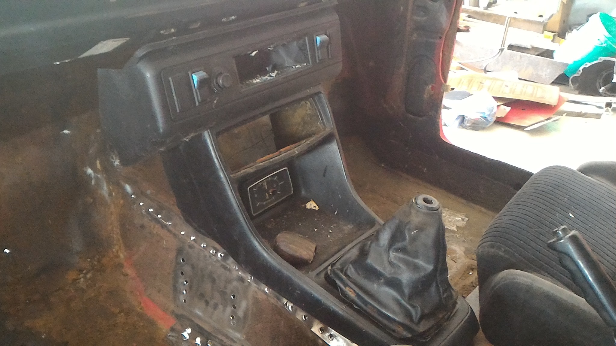
The second win for the day was a big parts haul from another of dad's many mates. There's a guy around whangarei that drives a 1100 mk1 estate as his daily and he's stashed away two mk2 estates as parts cars. After a quick chat he very generously offered any interior parts we wanted since he only wanted mechanical spares off of them. So from that I managed to score 1x back seat with full clown car spec upholstery
, 1x homemade purri gear knob, 1x center console, 1x gear stick boot
Oh and shitloads of other stuff like full seat belts, door panels, heater box, kick panels, glovebox, dash trim, steering column and wheel, and more. We made sure to bag and tag everything so we know exactly where everything came from. So definitely a couple of wins that day.
-
3
-


")


 Then after finally wrapping my head around how to get it all to work I sent the file to a classmate and he printed it out on his homemade 3D printer. I had to split it into four separate parts to fit it in the printer then glued them all together and put some model filler putty to smooth it all out.
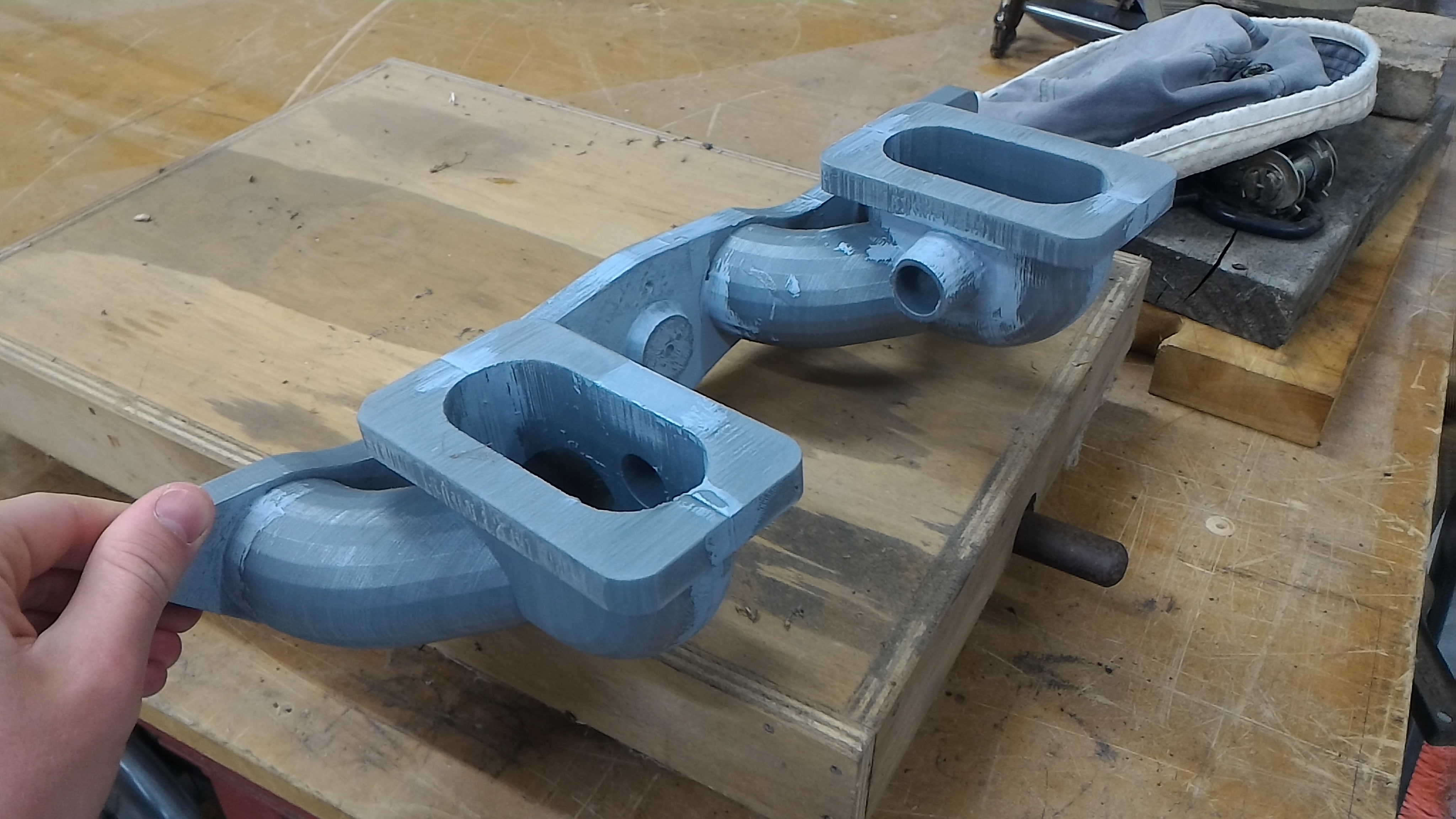

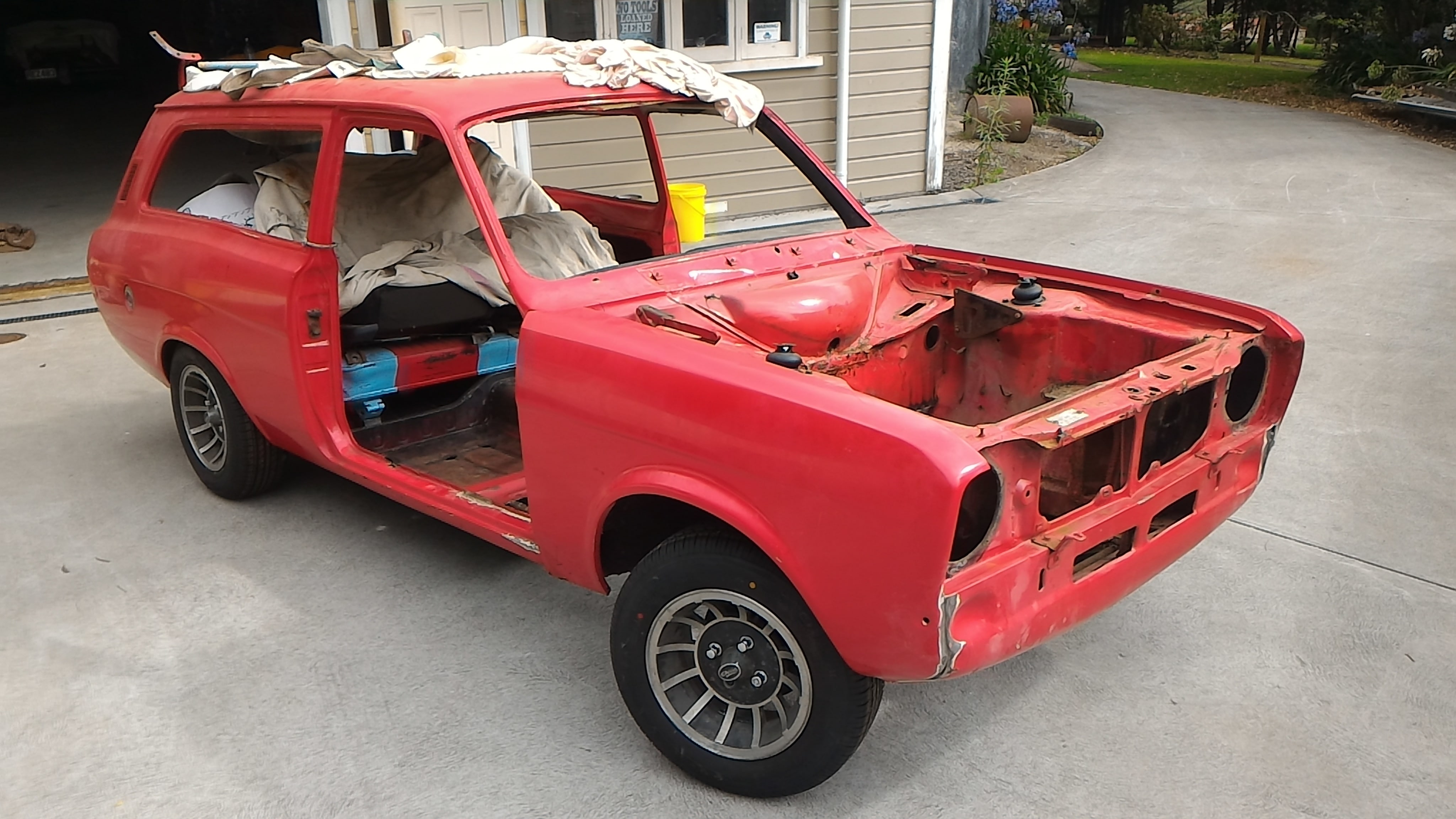
Hurmeez' 1977 Mk2 Escort Estate
in Projects and Build Ups
Posted
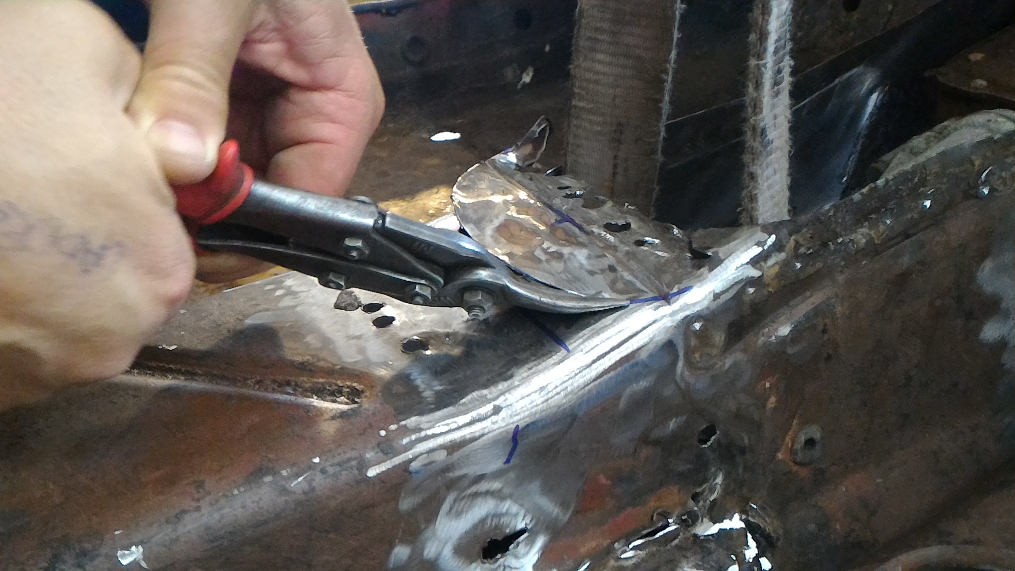
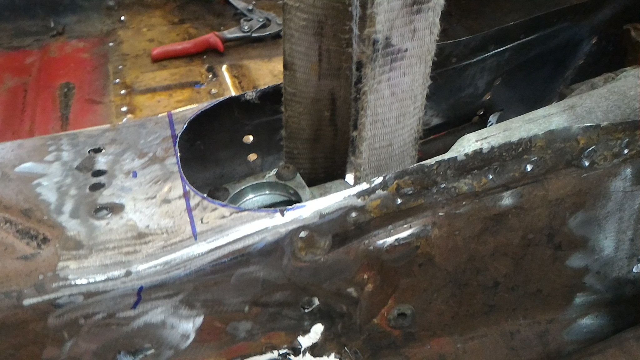
Then it was on to making up some rad support panels. I made up a wooden buck out of some MDF lying around and used that to form the ~20mm flanges on each one to fit the contour of the inner wing. One of them needed a bit of heat to encourage it to shrink around the corner but the other came around just fine. I used the bead roller to put in the inset portions to try and mimic the factory stamping shapes.
These last two are all the panels clamped in place to see how they look, and them all laid out to more easily see how they fit together.

The shorter one on the right was intentionally made that long but the asymmetry bugged the shit out of me so I ended up remaking it to the same length as the left hand one.