Hurmeez
-
Posts
341 -
Joined
-
Last visited
-
Days Won
1
Everything posted by Hurmeez
-
I accounted for the shrinkage of the ally by finding out how much aluminium is known to shrink from casting and increasing the size of the model by that much. There was a bit of porosity and some voids that had to be ground out and welded up but that was more down to the quality of the printing more than anything. If I were to do it again I'd do much more work on making nice rounded corners on everything to help the flow, rather than smoothing sharp edges with a die grinder like I'm going to have to. Also I'd try to get a higher quality print out of a better printer. It was made with a home built printer after all, and that showed in the final finish of the model. The port shapes aren't quite bang on but there's plenty of meat there to grind out to port match it nicely. If you look at it objectively the cost was really high at $500 for what it is, but it was more about the experiment on what was possible with the cool tech I had available to me. Thanks
-
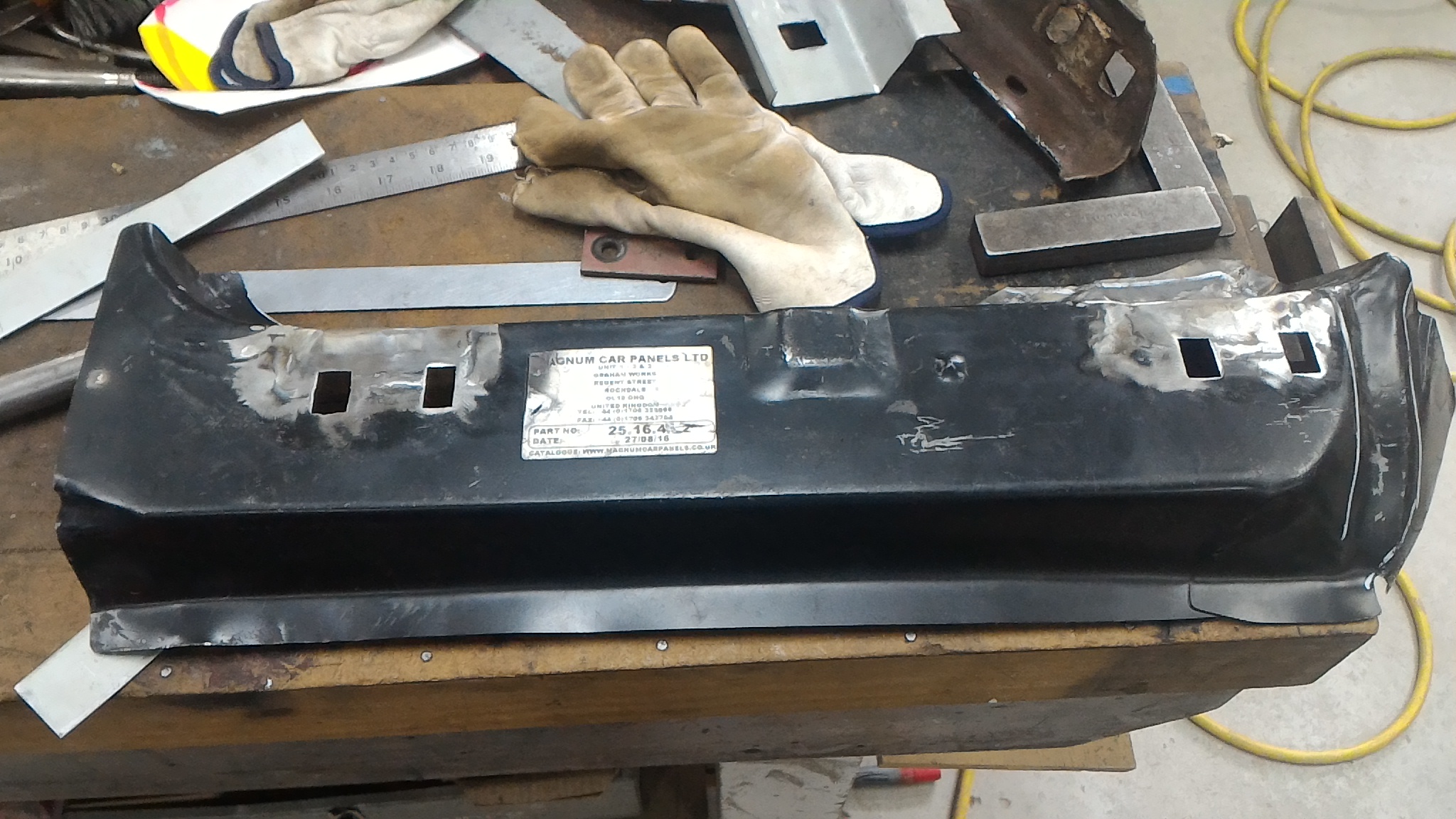
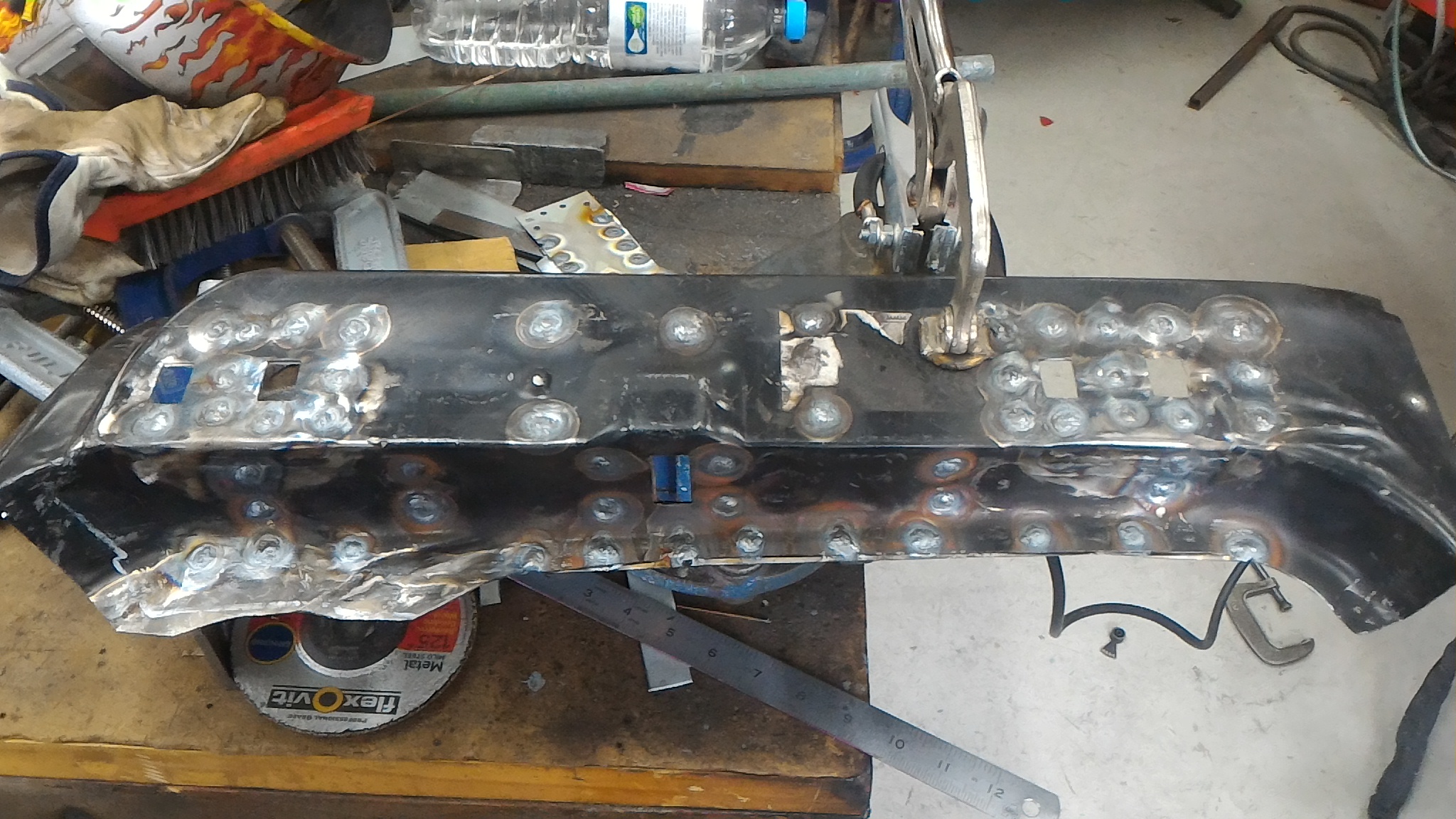
To finish off the sill part of the operation I needed to make up an inner sill panel. So that's what went and did. Efficient aye? So paper template, steel, hole, no hole, And all welded up. Only took about 20 minutes...(hahahahahahahah not)

-
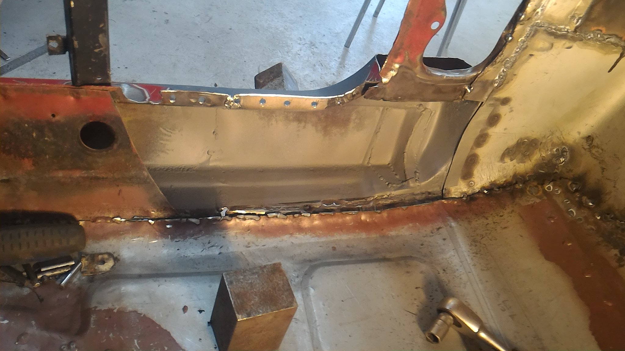
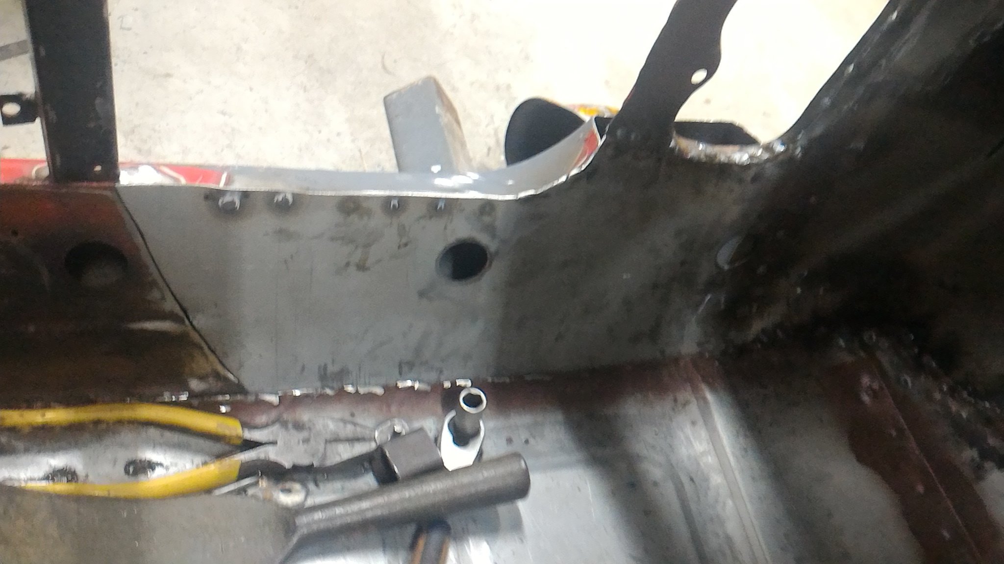
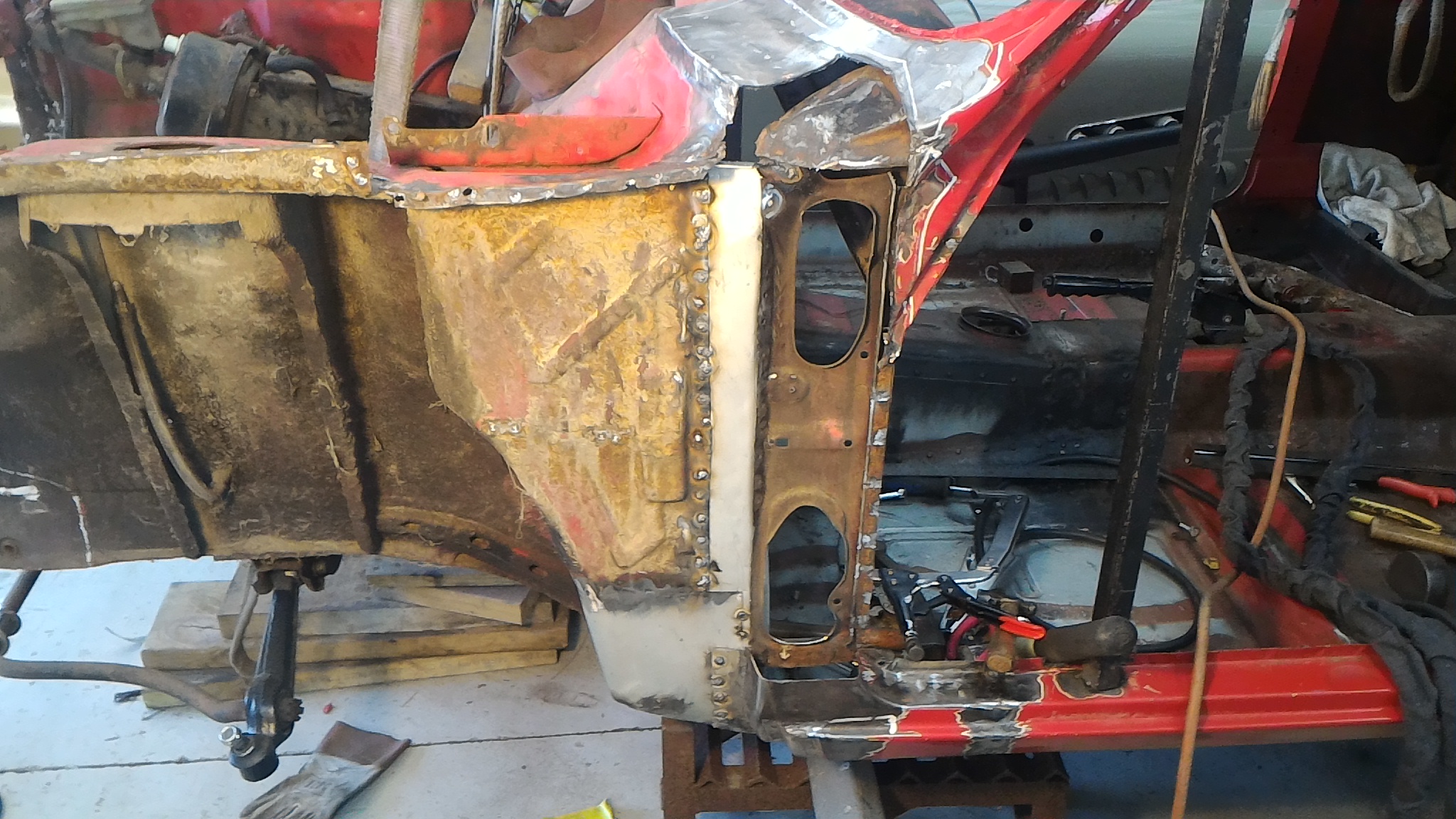
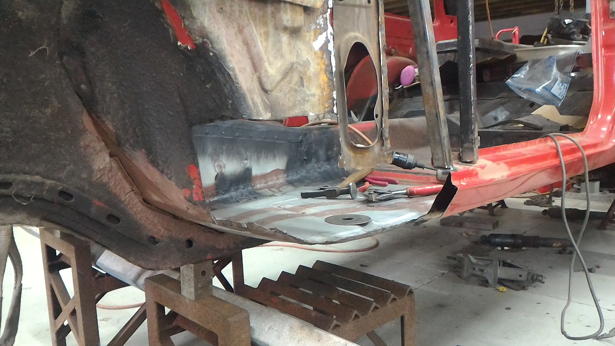
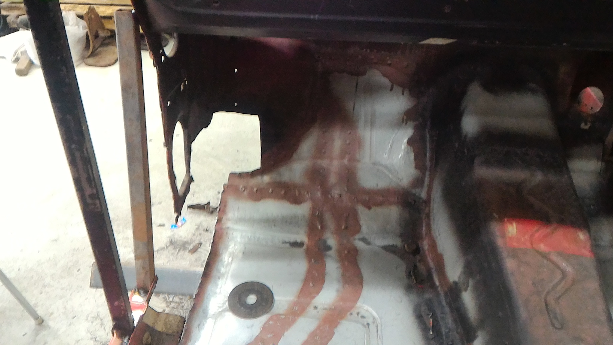
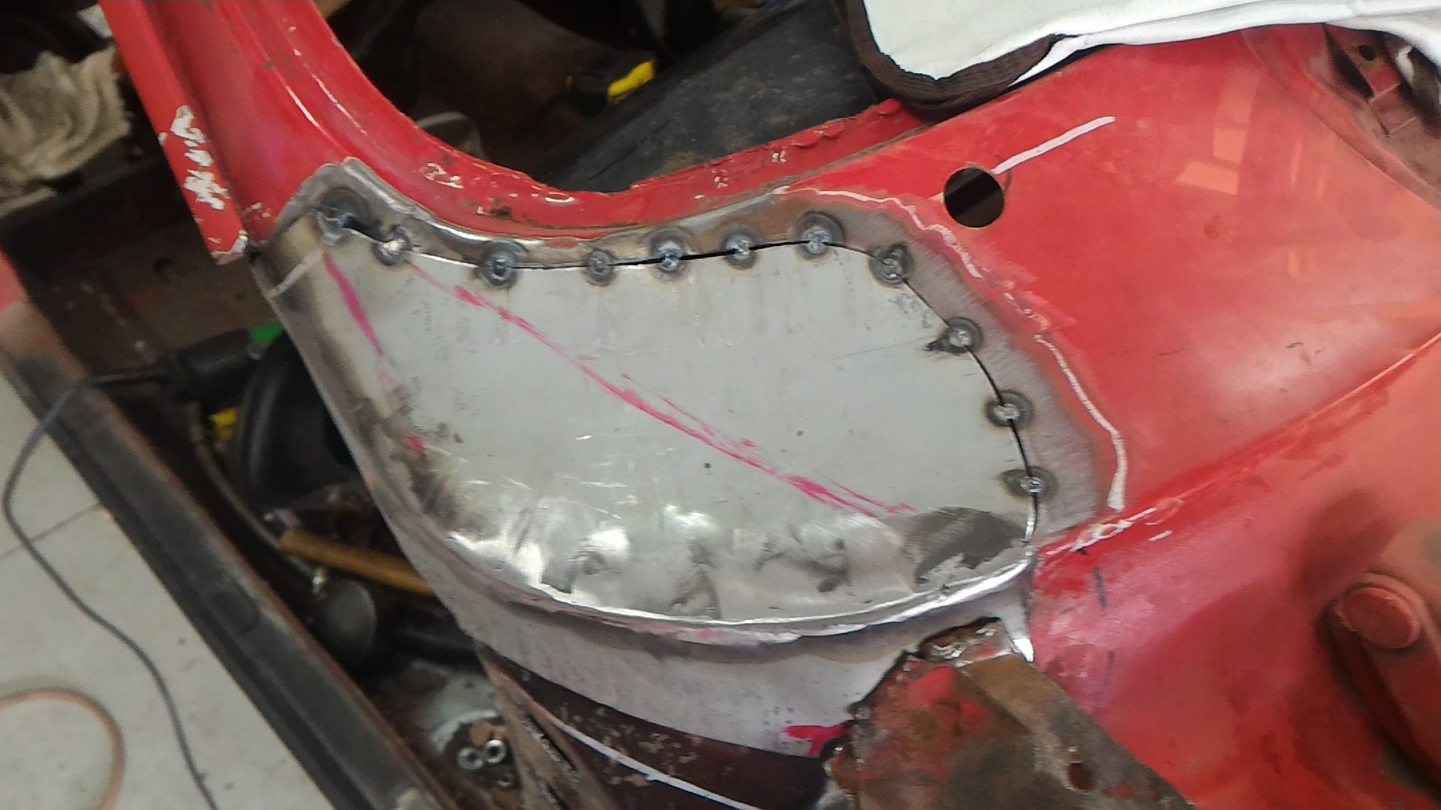
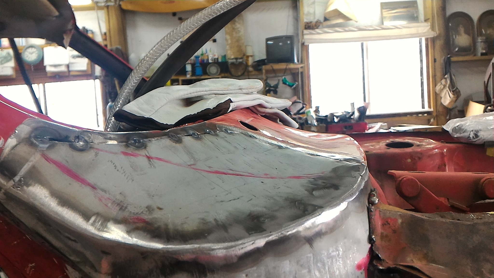
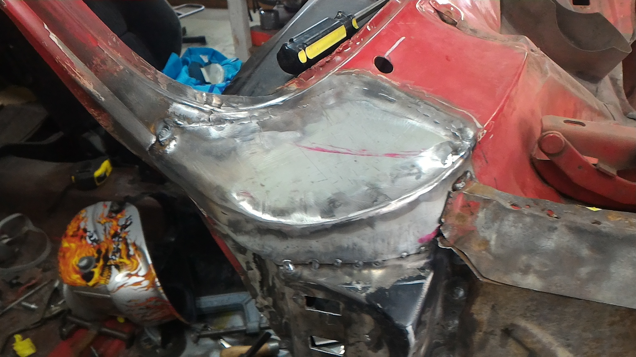
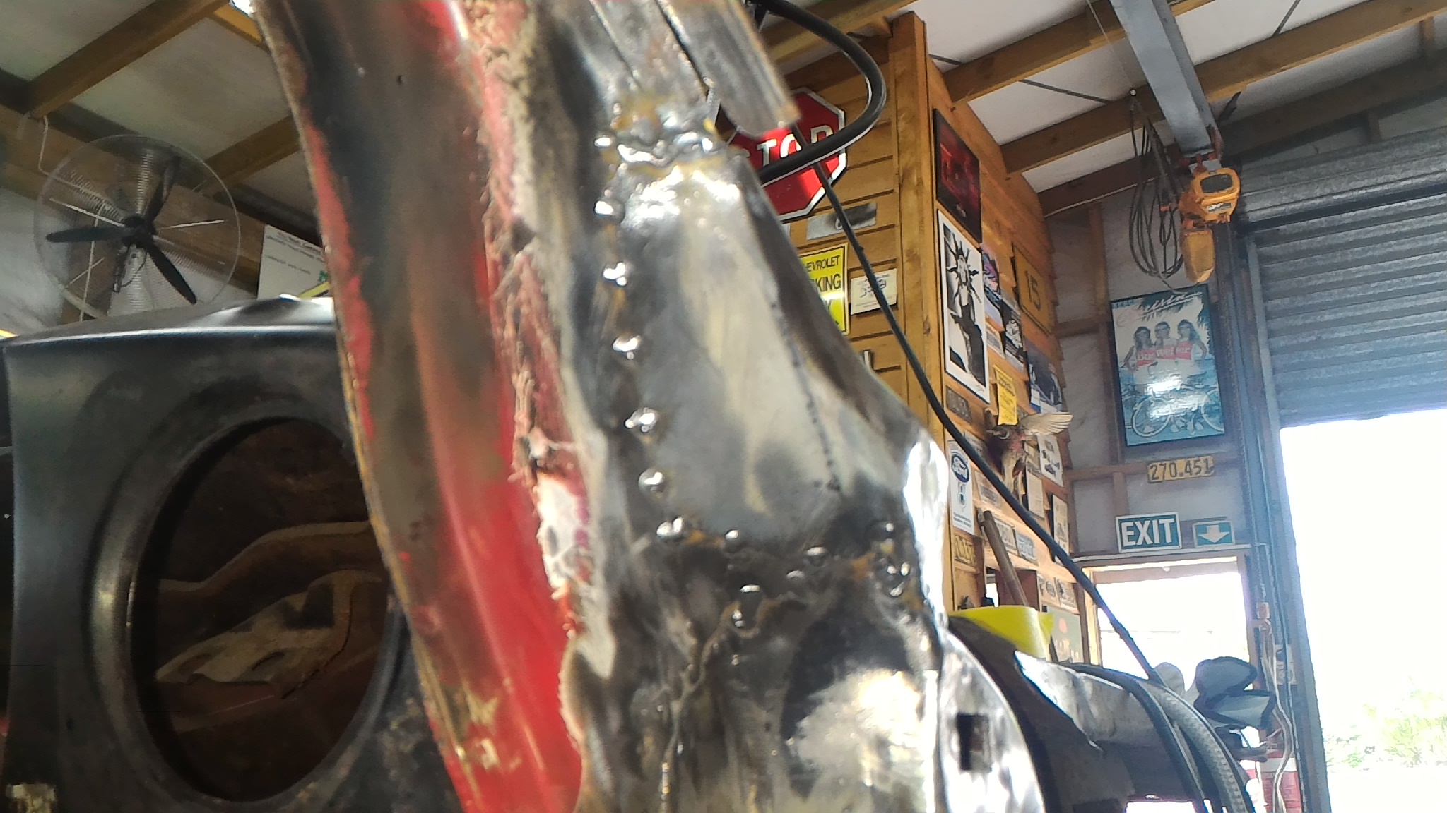
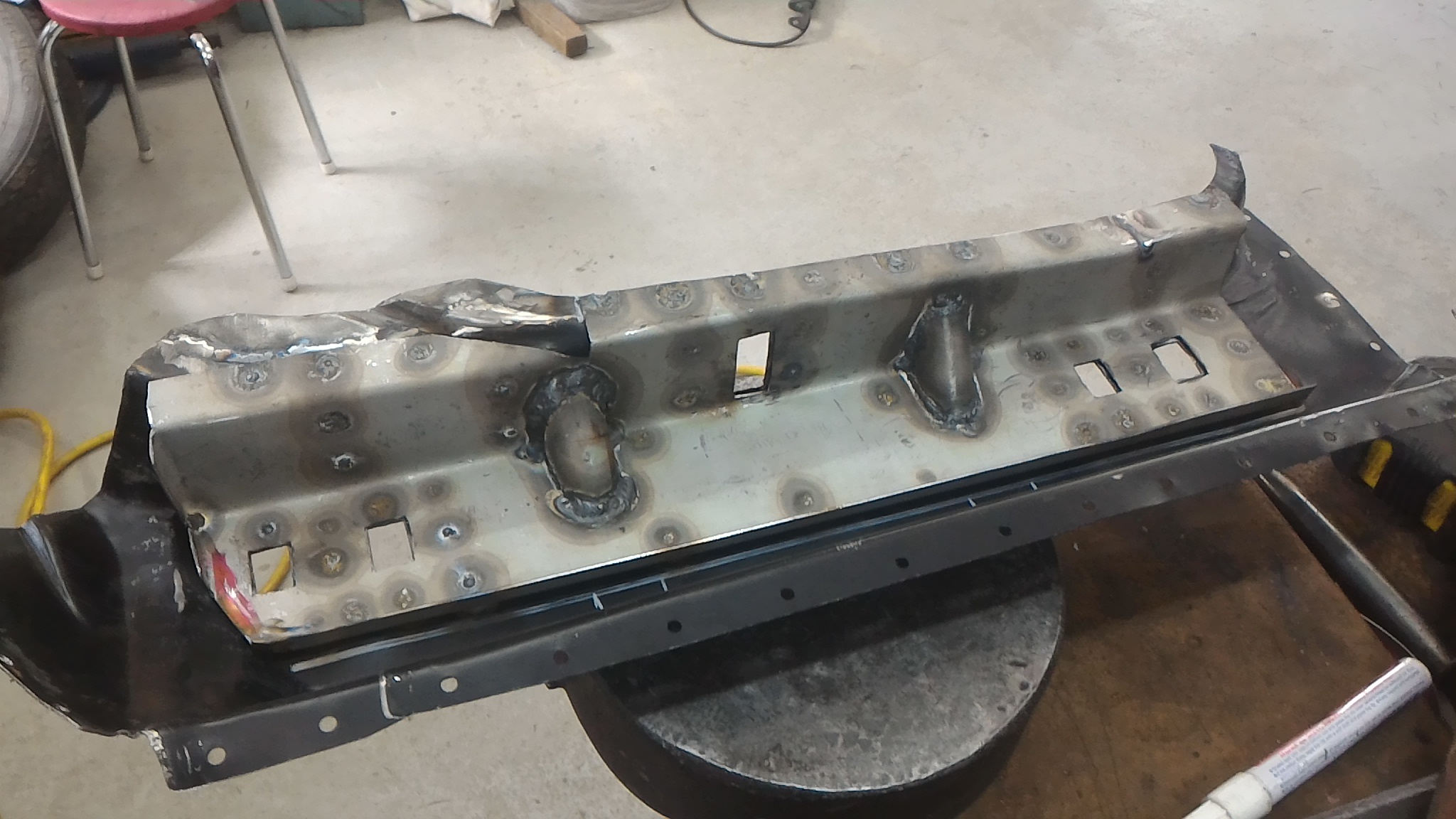
Now it's on to filling up that massive hole in the wheel well. I made up a quick and dirty paper template and transferred it to steel. Formed it up and offered it up to the hole. After some fettling I got it clamped up and tacked in. It was about now that I wanted to sort out that join between the splash panel and the inner A pillar. I could have replaced the whole panel but I'd rather not cut out any good steel if possible. So I cut out the rust and brazing over rust (wtf?) and made up a strip to fit in the gap. Plug welded it on as well as fully welding the wheel well panel and jobs a good'un Each bit done is one more bit I don't have to do.
-
Thanks very much
-
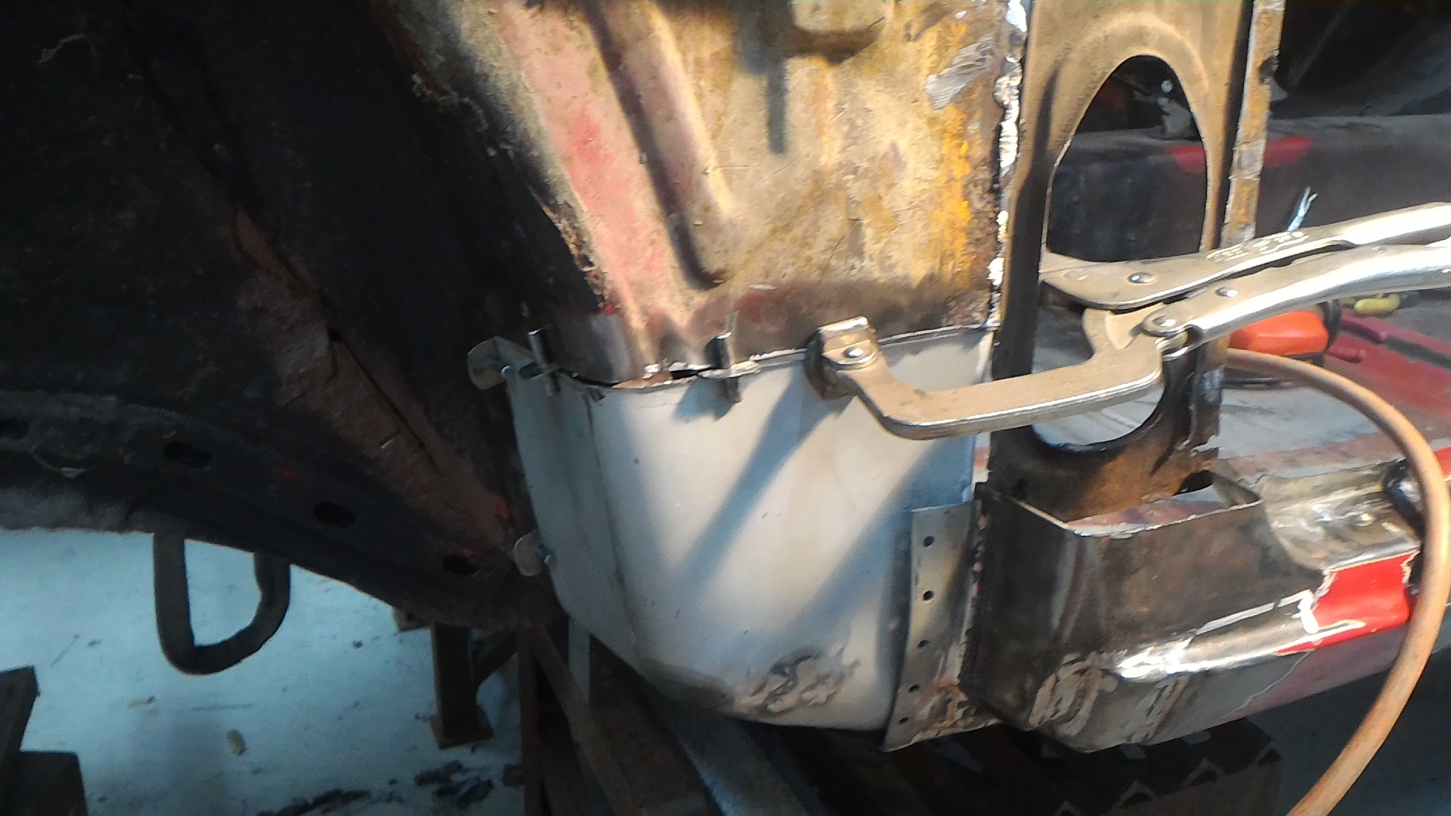
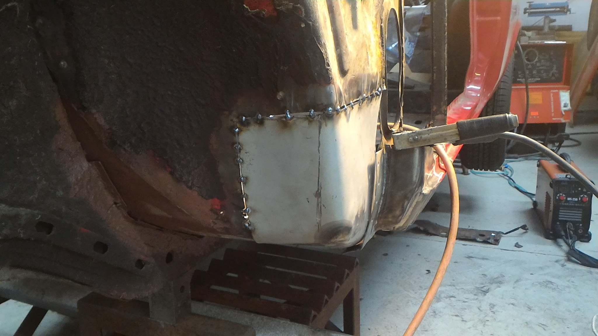
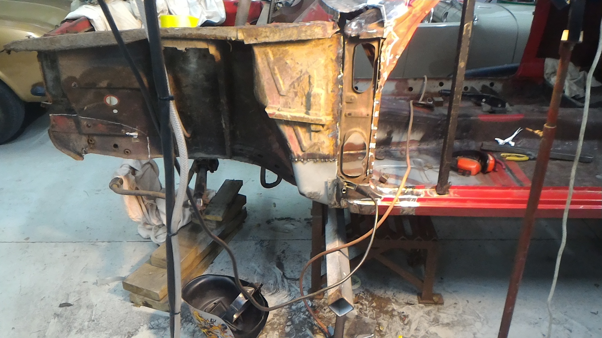
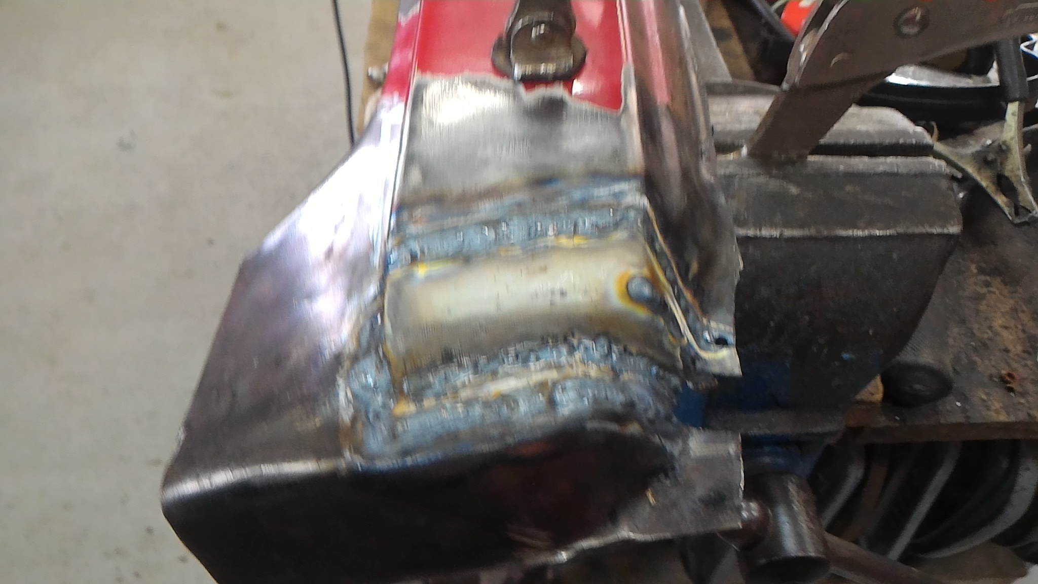
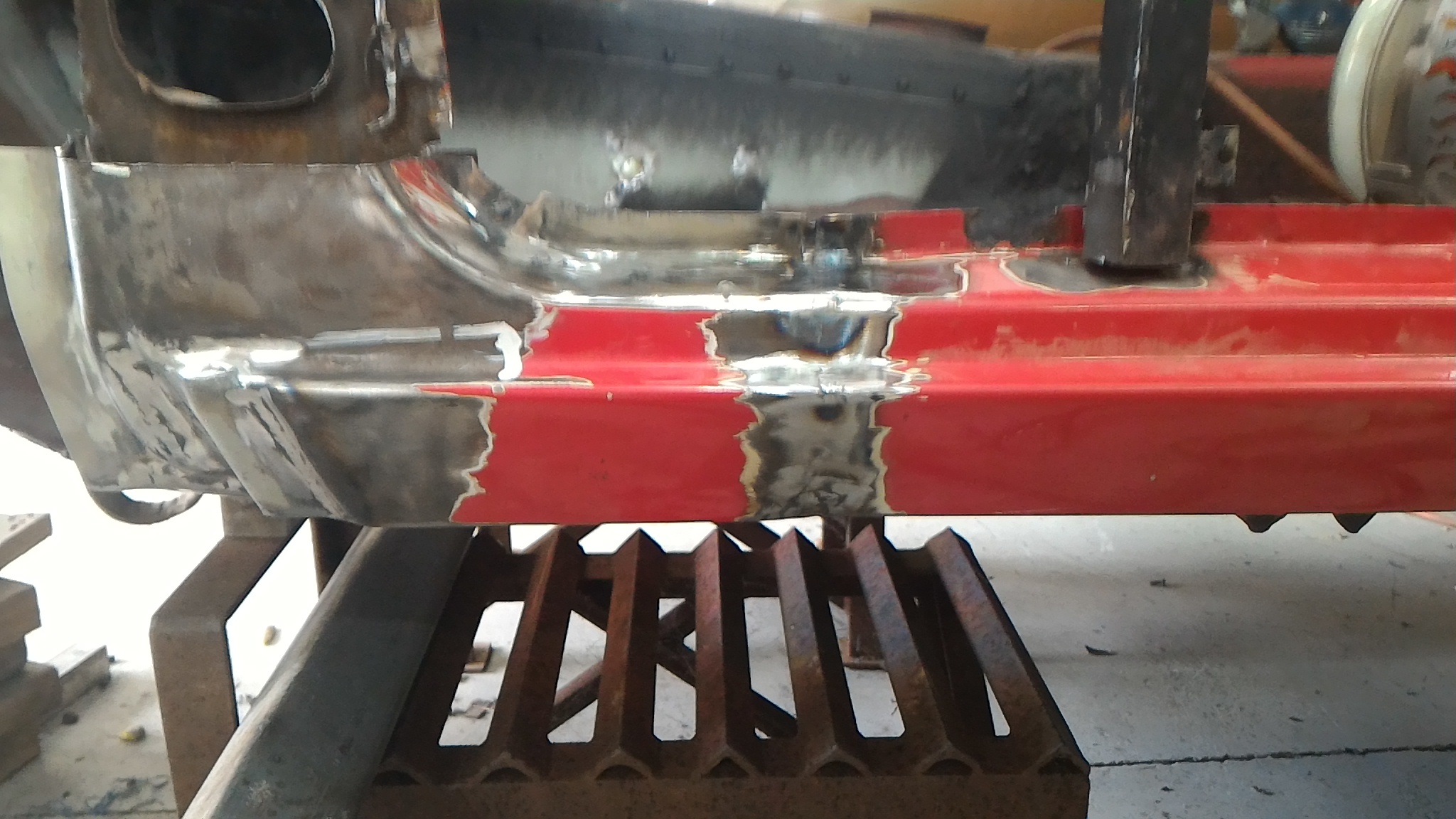
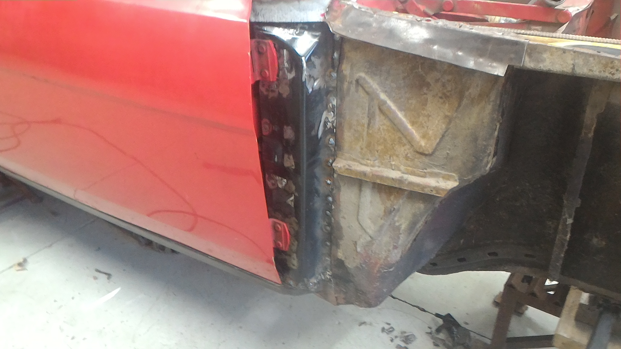
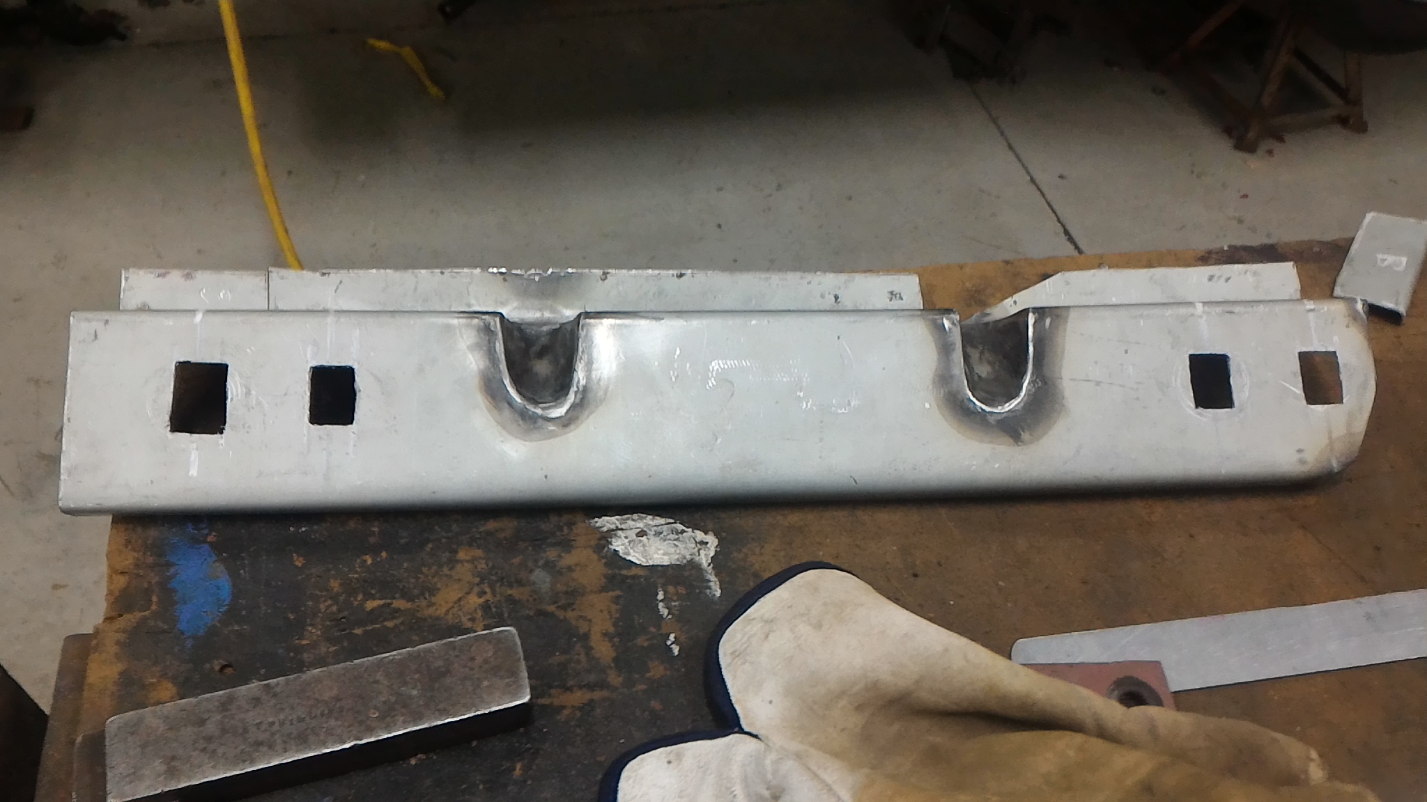
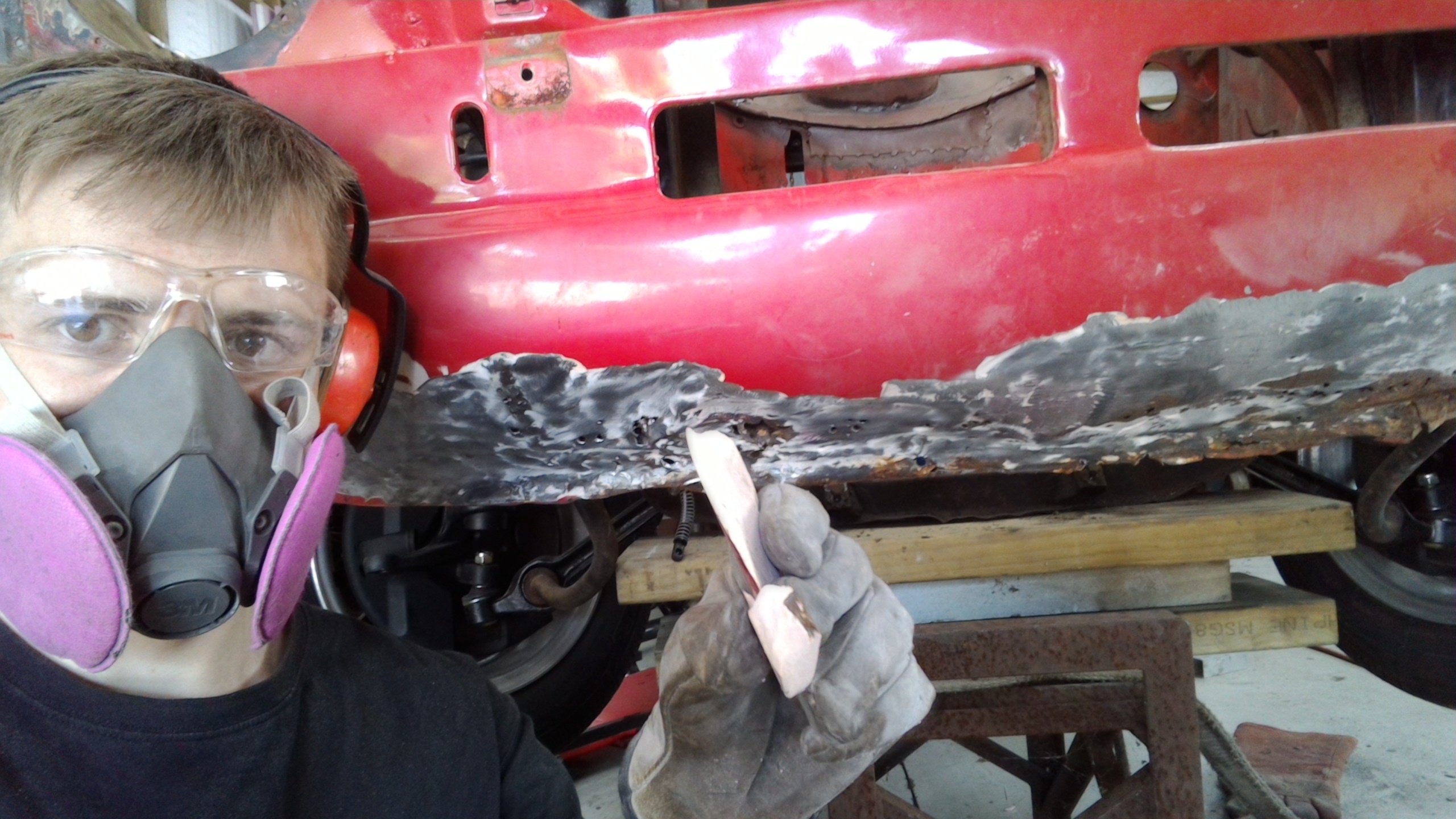
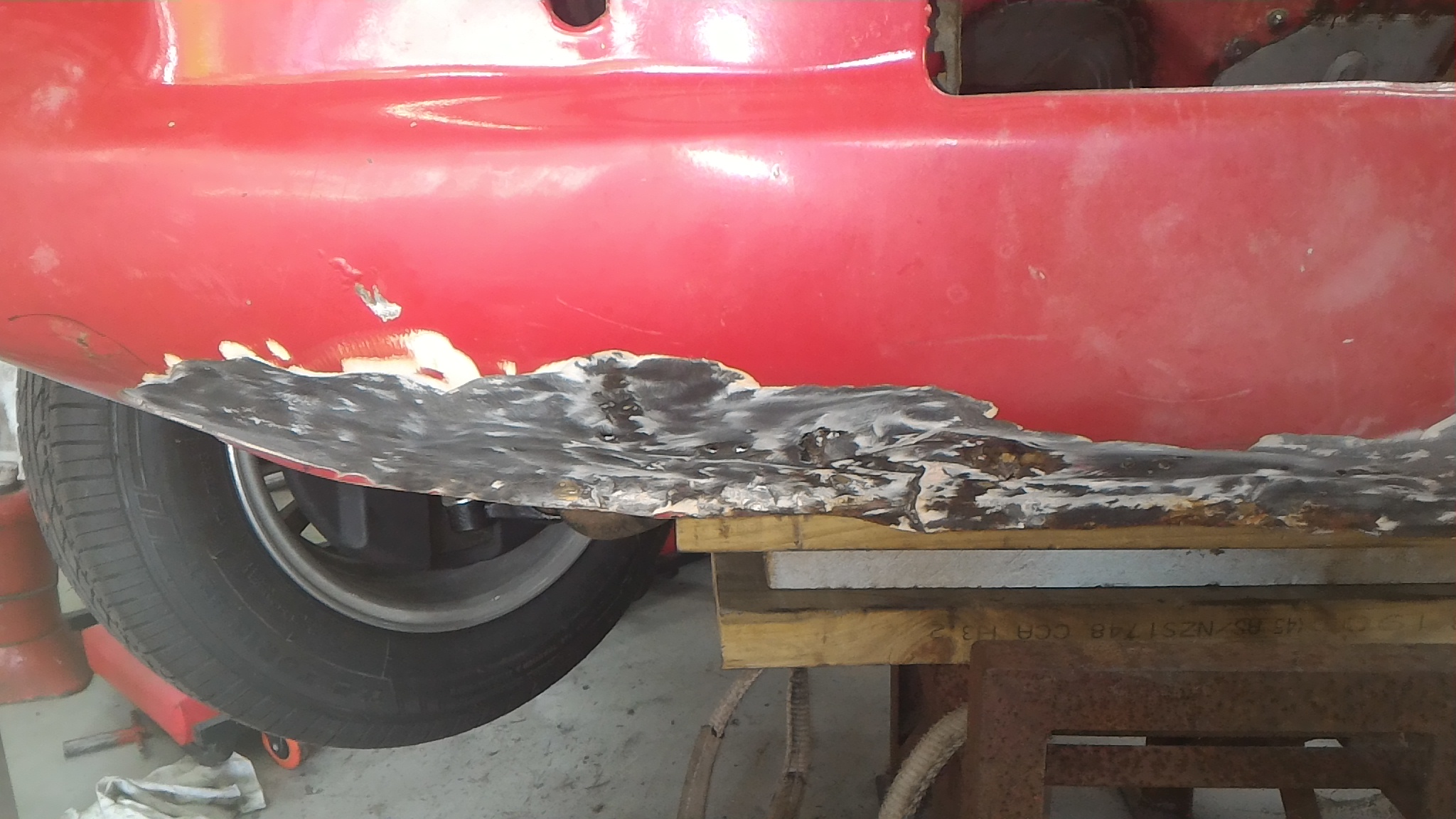
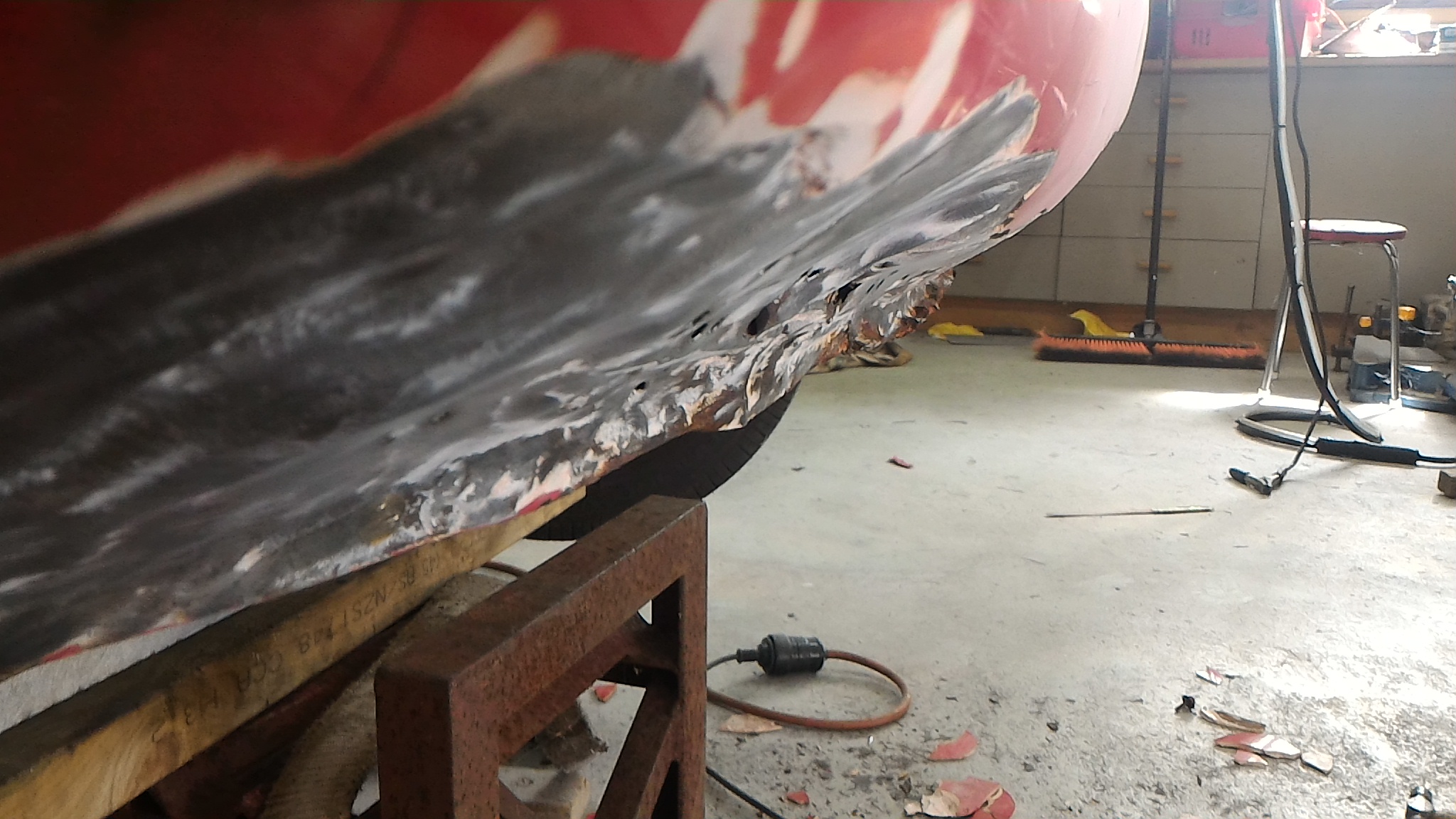
On to the other side. I tore the A pillar off this side and found another piss poor repair attempt in the wheel arch. So while I was there I cut it all out as well as the front portion of the sill which needed rust repairs as well. When I cut the sill off I was particularly careful to keep the steel I ground out to a minimum. I used the thinnest slitting disk we have as you can see in the last photo, and kept it down to about 1mm or so lost material. The inner sill was cut out too for the same reasons. As you can see I also added in some bracing since I'm taking out so much structural material and I'd rather be safe than sorry. Then I set about rebuilding the front of the sill. I preferred at this stage to tack with the MIG and do the proper welding with the TIG as the photos show. Again, not my best work but as they say, "a grinder and paint make me the welder I aint" Then I used the through panel clamps to hold the sill in place while I tacked it back on. I used the original splitting disk to set the root gap of the weld to make doubly sure it was in exactly the same place as when it came off. Then it was tacked and fully welded back on, taking breaks and letting it cool to keep distortion down to a minimum. Turned out pretty good. Skim of filler, paint, you'll never know.
-
Keen eye on you @Valiant. Dad's got a 39 ford coupe deluxe in the back with some pretty awesome panel work being done on it. Here's his build thread if you're interested... https://www.jalopyjournal.com/forum/threads/kiwi-1939-coupe-de-jure-runnin-from-johnny-law.853214/
-
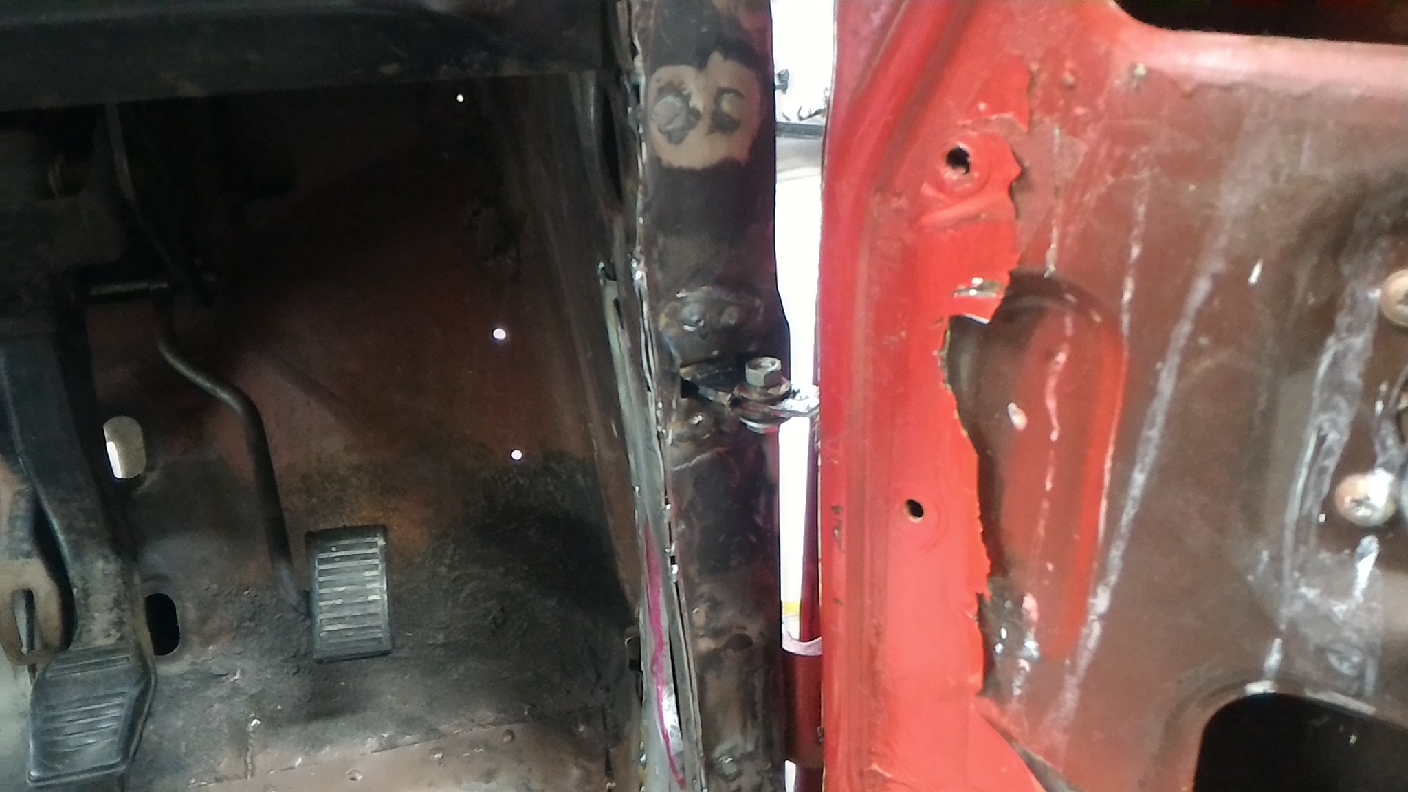
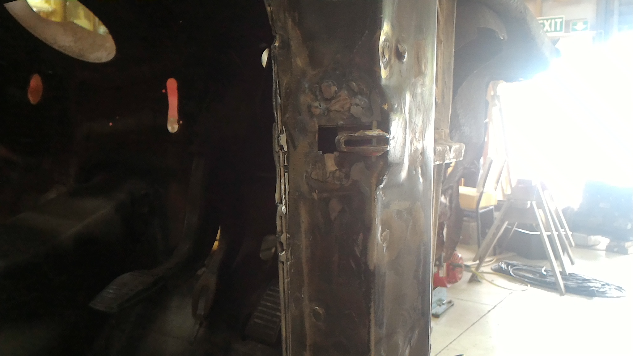
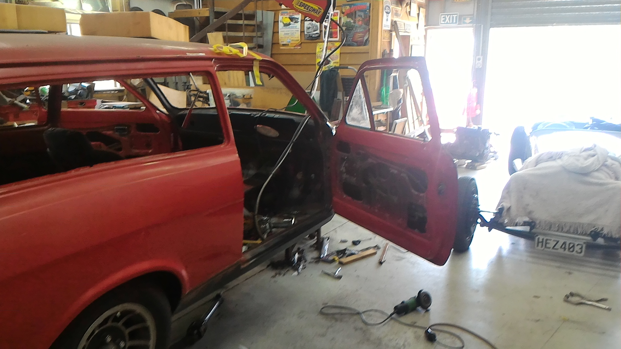
So I slapped that bracket in and bolted to door up to look at the fitment. As you can see, somethings not right. The door doesn't open near far enough and after some investigation I realised that the check strap bracket was about 5mm to far inboard. That meant the check strap couldn't extend far enough to allow the door to open properly. So out had to come the check strap bracket. Unfortunately some dick had plug welded the snot out of it and so I had to drill out the welds, shift it over, and weld it back in. I love making more work for myself.
-
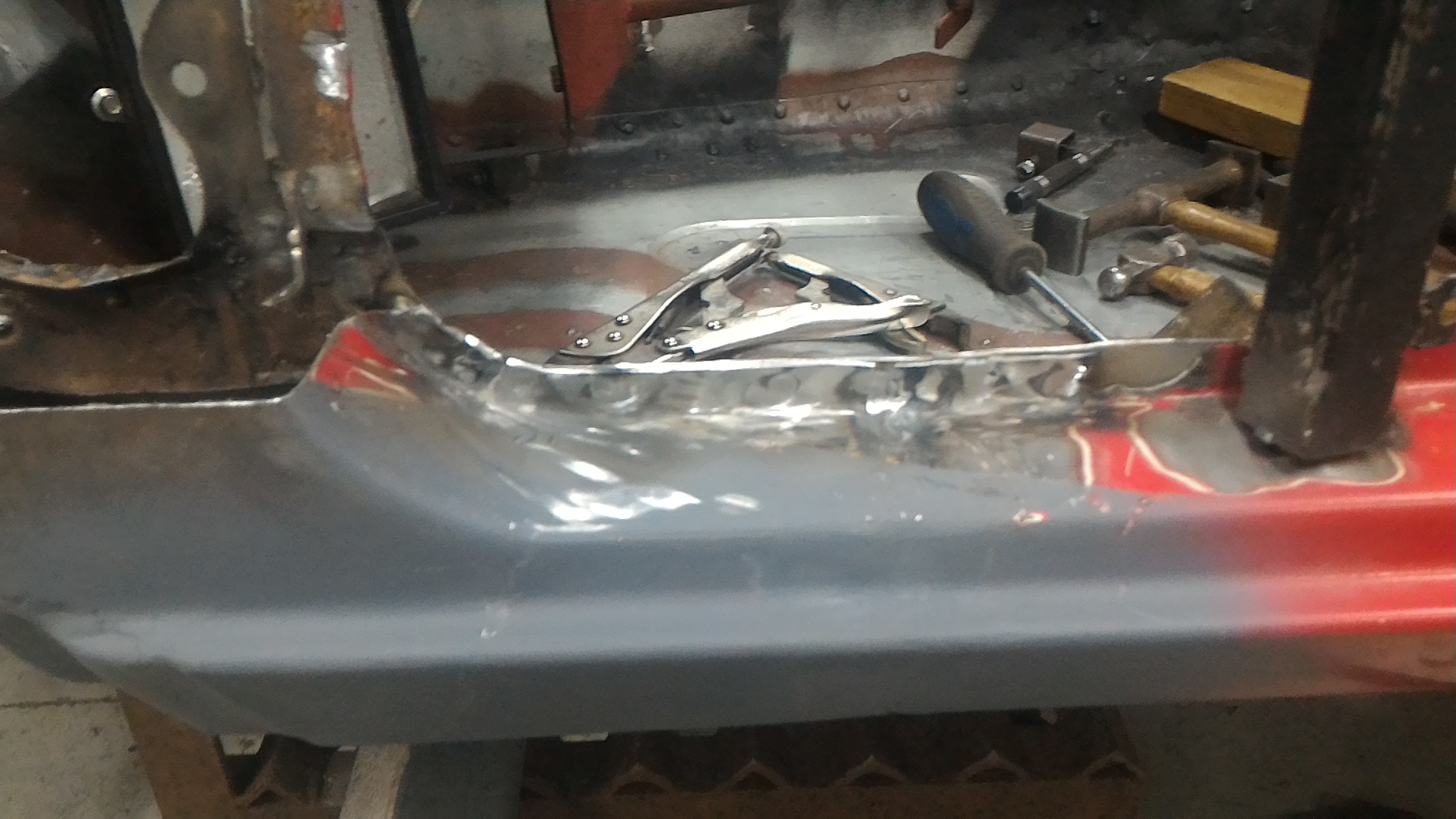
Then it was just weld the new cowl panel in. Tacked first Then slowly and carefully fully weld it all back in. Here it is all ground back And stitched around the bottom When I fitted the door I found that the patch was slightly too girthy () and the edge of the door would touch it when it was shut. My solution at the time was to make up some spacers for the hinge to hold the door out from the cowl. Like so... You can see the plate sandwiched between the hinge and the pillar. Now don't roast me. I know this is a terrible solution to a problem I have created myself. Don't fret. It gets fixed. This all happened six months ago remember. I then went and welded in the door check strap bracket. This was the beginning of another debacle, as the next post will detail...
-
And boom! It's on the car.
-
Next job was to prep the new repro A pillar panels for welding in. The original pillar has a reinforcing panel welded in the back side of the outer skin. So I set about reproducing that from some shiny new steel. The gussets are there to replace swages that continued around the fold in the panel. I can tell you first hand that they are a real bitch to try and replicate (read: I fucked one royally and had to start the whole lot over trying to do it) so I opted to do these gusset type things instead. They provide much more stiffness than the stock piece anyway. Then I had to modify a mk1 escort A pillar repair panel because the mk2 estate pillar is very similar but uses mk2 style bolt on door hinges instead of the welded on mk1 style. Like so... Then the two get zapped together with a bajillion plug welds to make sure that shit aint going nowhere. I used the TIG for all these plug welds but it was such a pain in the butt and took so long that I would use the MIG next time. It came out pretty neat though I thought.
-
So I tore the A pillar off and removed the rusted lower half of the inner pillar and replaced it with nice new steel. The welds weren't my finest work but it't not coming out any time soon.
-
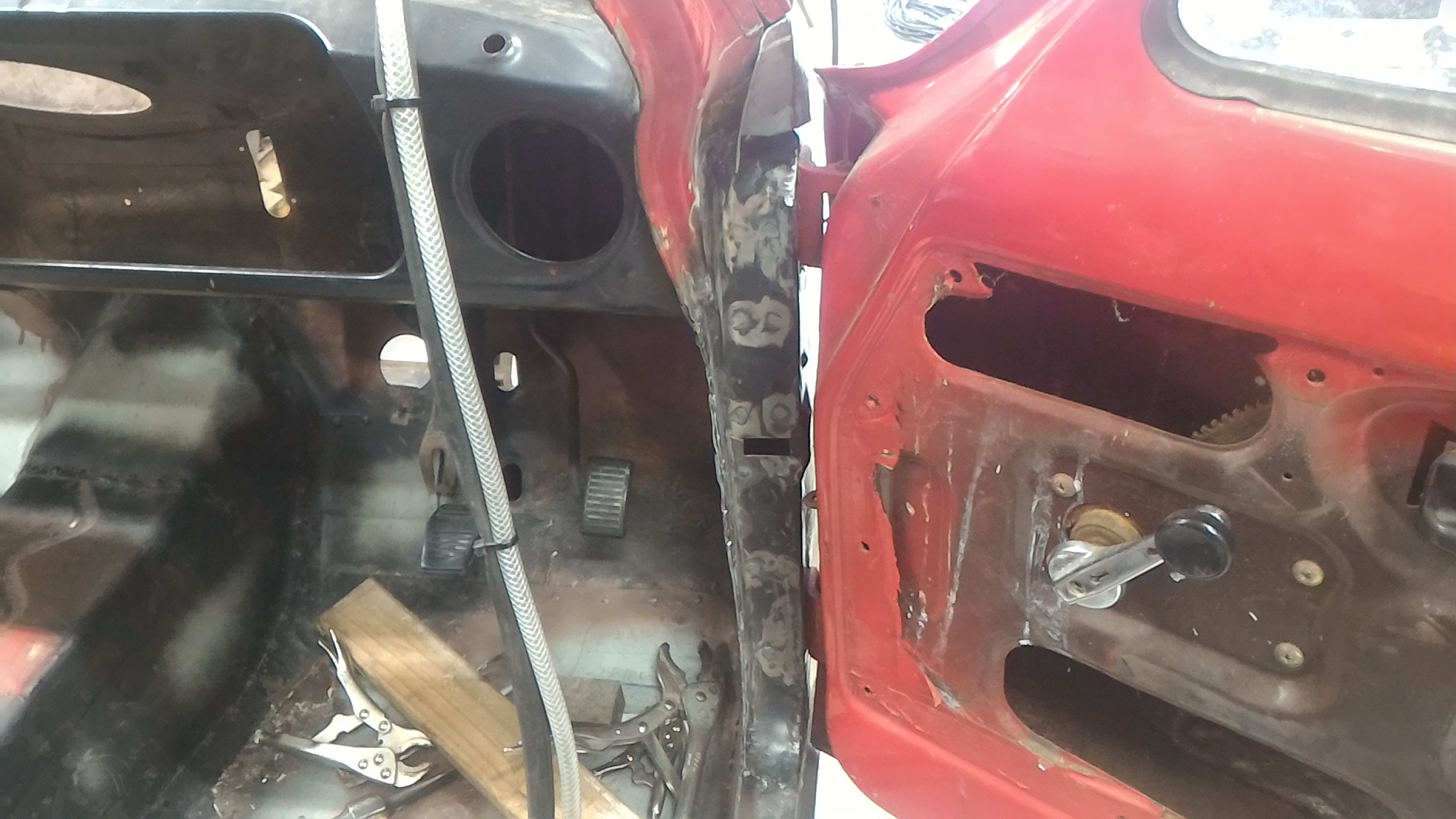
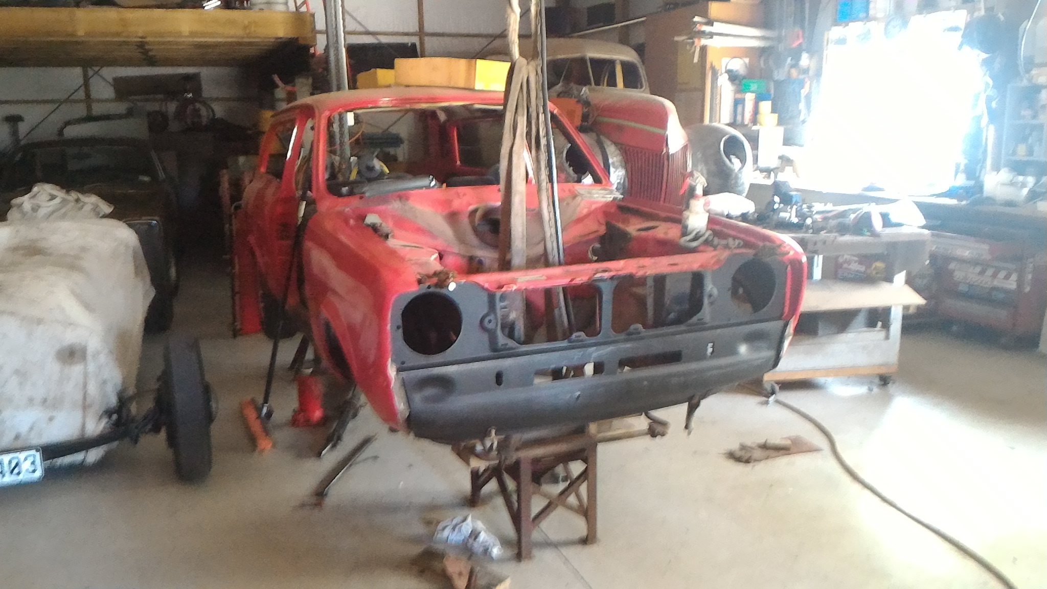
It was at this point that I realised that I couldn't weld any of these panels in yet. To weld them in I would need to know exactly where the front panel wanted to go. To know where the front panel wants to go I need to know where the guards want to go so I can match all the lines up. Since I need to repair the guards I need to pull them off. To know where to put them back on after I repair them I need to know where the doors are to match up the lines. To make sure the doors are hung in the right spot I need to sort out the A-pillars. So that's whats next. Well sort of. Looking at the state of the a pillar after cleaning all the paint and shit off it tells me that the whole shebang needs binning and starting over. To pull the old a pillar out and replace it properly I need to get to the top of it. Are you spotting a pattern here yet? So I need to cut a part of the corner of the cowl out to gain access and I'll just weld it back in later on. Or so was the initial plan. I cleaned back the pain around the lower corner of the windscreen post to see what I'm dealing with a find a big old ugly patch. So now this has turned into another rust/"repair" repair. Before I cut out all the bad steel I formed up the replacement panel over the top to get the right shape. So that's that panel tacked up into shape. Now I can move on to deeper and dirtier bits of the beast.
-
Then it was on to making up some rad support panels. I made up a wooden buck out of some MDF lying around and used that to form the ~20mm flanges on each one to fit the contour of the inner wing. One of them needed a bit of heat to encourage it to shrink around the corner but the other came around just fine. I used the bead roller to put in the inset portions to try and mimic the factory stamping shapes. These last two are all the panels clamped in place to see how they look, and them all laid out to more easily see how they fit together. The shorter one on the right was intentionally made that long but the asymmetry bugged the shit out of me so I ended up remaking it to the same length as the left hand one.
-
Next I made some repair panels for the front of each chassis leg. They were fairly simple. Started with a cardboard template then transferred it to steel and folded the lot up. There is actually an inner and outer piece to each of these just like the factory chassis leg to add rigidity but I didn't get any photos of the inners. This is the chassis leg and front panel sitting in place. I haven't removed the rad supports yet because I wanted to make all the replacement panels first in case I chop out the old panels and everything moves around and I don't know where to build to. I have to keep making posts with just a few photos because they're too big file sizes. I thought I was being clever at the time getting the highest possible quality photos from my phone. It's biting me in the bum now.
-
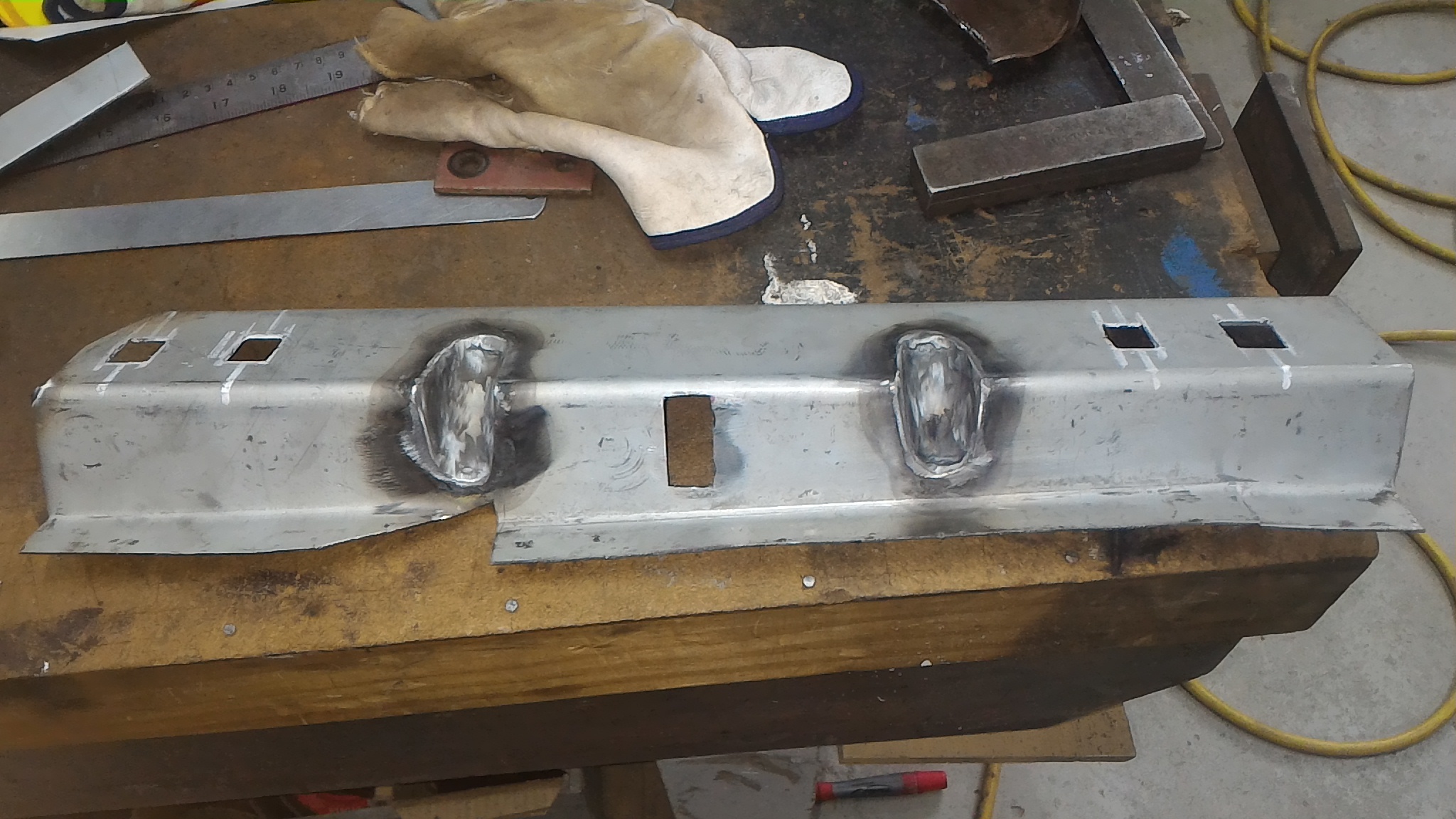
Actually nah screw that I'm gonna keep going. Once the front panel was off the true extent of the corrosion in that part of the car was obvious. So more fab work was called for. I started off by making a new radiator support/front panel mount. I folded the main bend first then used a slitting disk to split the fold in the middle part where the rad mounts. Then I carefully reverse folded these two new flaps and zipped the whole lot up with the TIG. By doing the folds this way I was able to keep the amount of welding to a minimum and therefore the amount of distortion too. Then it was a doddle to put some plates in to blank off the holes and fold up the relevant mounting tabs and there you go, one piece done. You'll note the slight curve in the bottom part which follows the curve of the valence to be welded to it. This design is different to a stock escort where the rad cutout wouldn't have been there at all. By doing it this was I have made a neat solution to shift the rad forward in order to clear the longer pinto motor. Mint.
-
Glad you like it 64vauxhall. I'll definitely keep the updates coming, it's bloody addictive once you're on a roll.
-
So the only option was to arsehole the whole lot and start again. Banished to the wall of offerings And a pretty new one from palmside I think I'll call it there for tonight. We'll pick up the tale again sometime tomorrow.
-
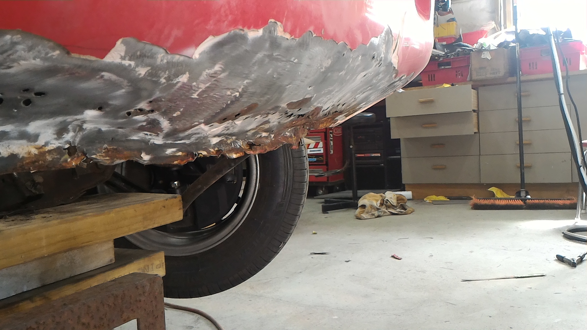
Next thing I got on to was investigating the small amount of rust you could see on the bottom of the front valence panel which you can sort of see in this photo. I could see a bit where there was some bog lifting away from the rusting steel underneath. So I put a screwdriver in behind the bog and chipped it out to see how far the bog went. And went. And went. There was a bit of bog on there actually. That's a size 10 boot and the pile is as high as the top of it. This is the state of what the bog was covering. The photos struggle to portray just quite how much the panel is pushed in. It was a mess. This is some of the thicker chunks of bog that came off. Please note that they're directly end on to the camera. That is actually how thick it was. There really are some gifted "panel beaters" out there.
-
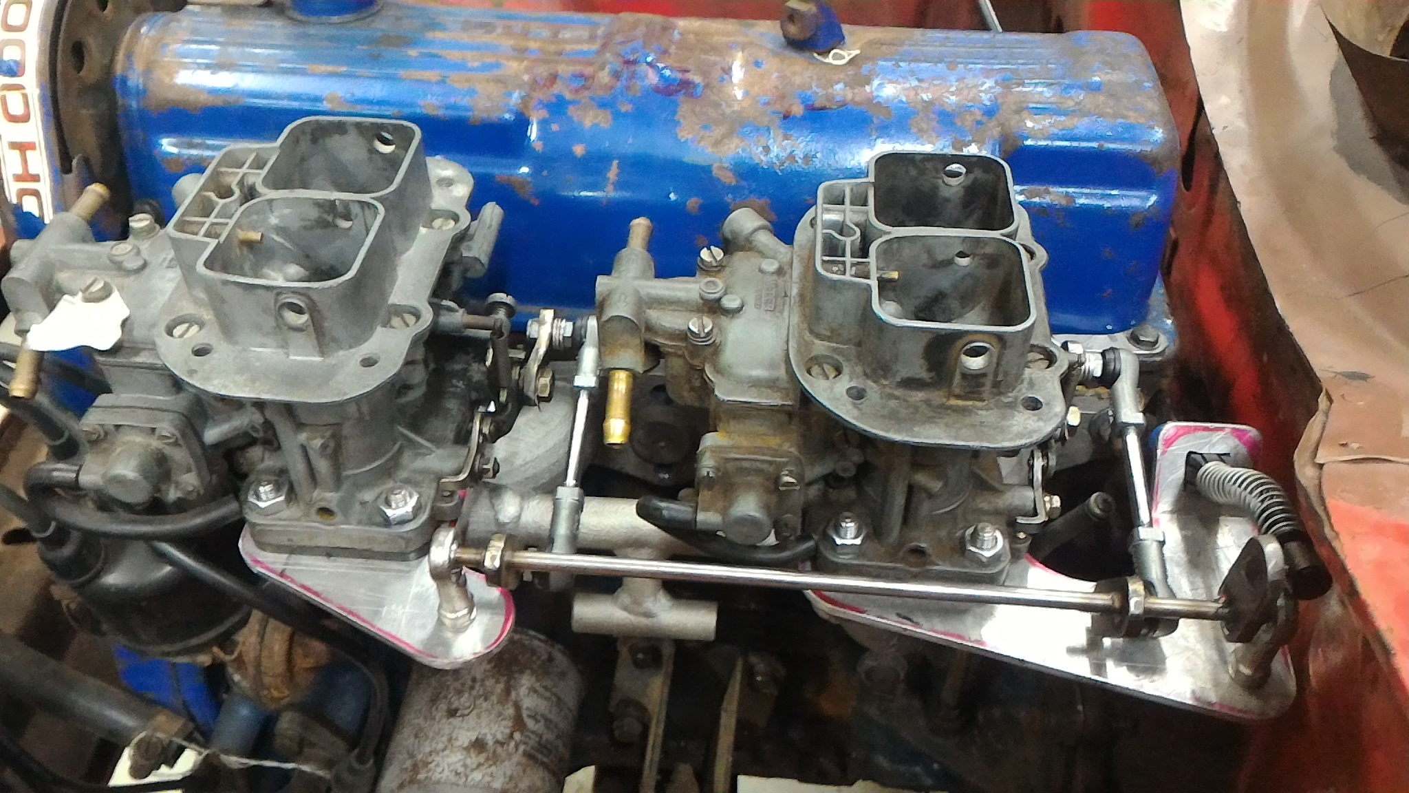
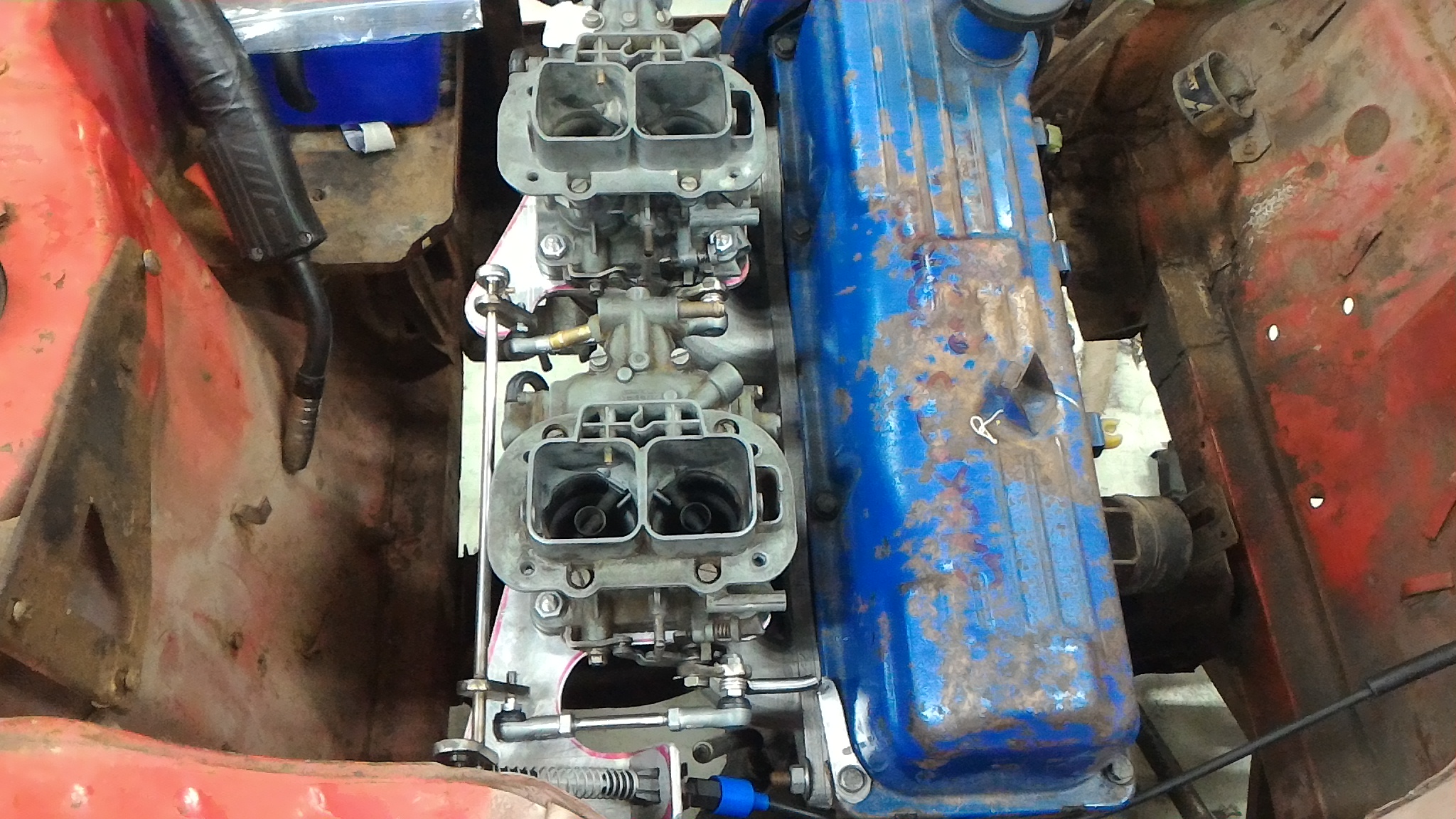
My next mini project was sorting out the twin carb linkage setup. I drew a lot of inspiration from the setup on my dad's 1600 but made a few tweaks. His is designed with the primary venturis furthest from the intake ports with the idea that when the secondaries open they have a straight shot down the thing's neck. In the interest of throttle response I've decided to instead put the primaries closest. This probably has little real world effect but I liked how it sounded. As you can see from the photos, there is a central stainless shaft mounted by a pair of rose joints, themselves mounted to two alloy plates clamped between the carb and the manifold. Off of the rod are mounted three stainless arms. The first is connected to the standard RS2000 throttle cable. The other two are connected to what I can only describe as miniature track rod ends which themselves are connected to another set, then the final linkage onto the carb. I back of the envelope calculated the lengths of the different arms to give me full pedal travel for full butterfly travel, hopefully avoiding a super twitchy throttle like the one in my dad's car. I also added an extra return spring on the cam cover just in case. In hindsight I want to revise the linkage with the two tie rod end things because they are both right hand threaded onto the central rod. This means I can only adjust the length of this part by one full turn relative to each other which would make balancing the two carbs damn difficult, if not impossible. Here is a video of the linkage in action, And here is a bonus video of milling up the carb face of the manifold. A huge thanks to Earle Tito Engineering Ltd for going the machining.
-
I'm 18 in a month. All I can say is I have a very patient father. Funny you should mention doing things properly. The amount of "repairs" we've found on the car so far is unbelievable. Epoxying steel patches over rust is basically the same as welding in a repair panel isn't it? (sarcasm)
-
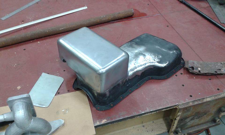
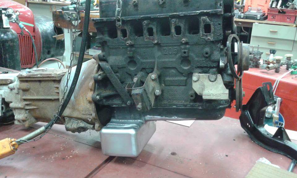
Dad modified the pinto sump to clear the escort cross member because while an alloy RS2000 unit would be nice, the price is a bit excessive. I did some rough calculations to make sure it's close to the stock volume. Note the cutout to avoid the clutch cable. Not shown in the photos is the baffle added later on.
-
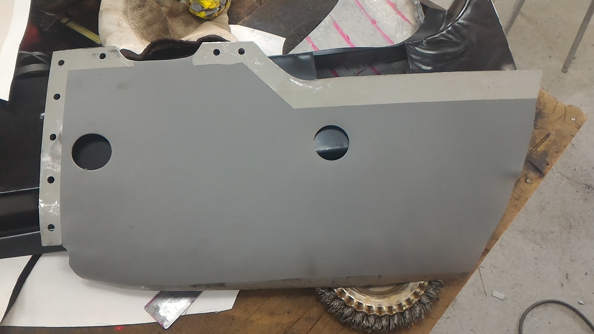
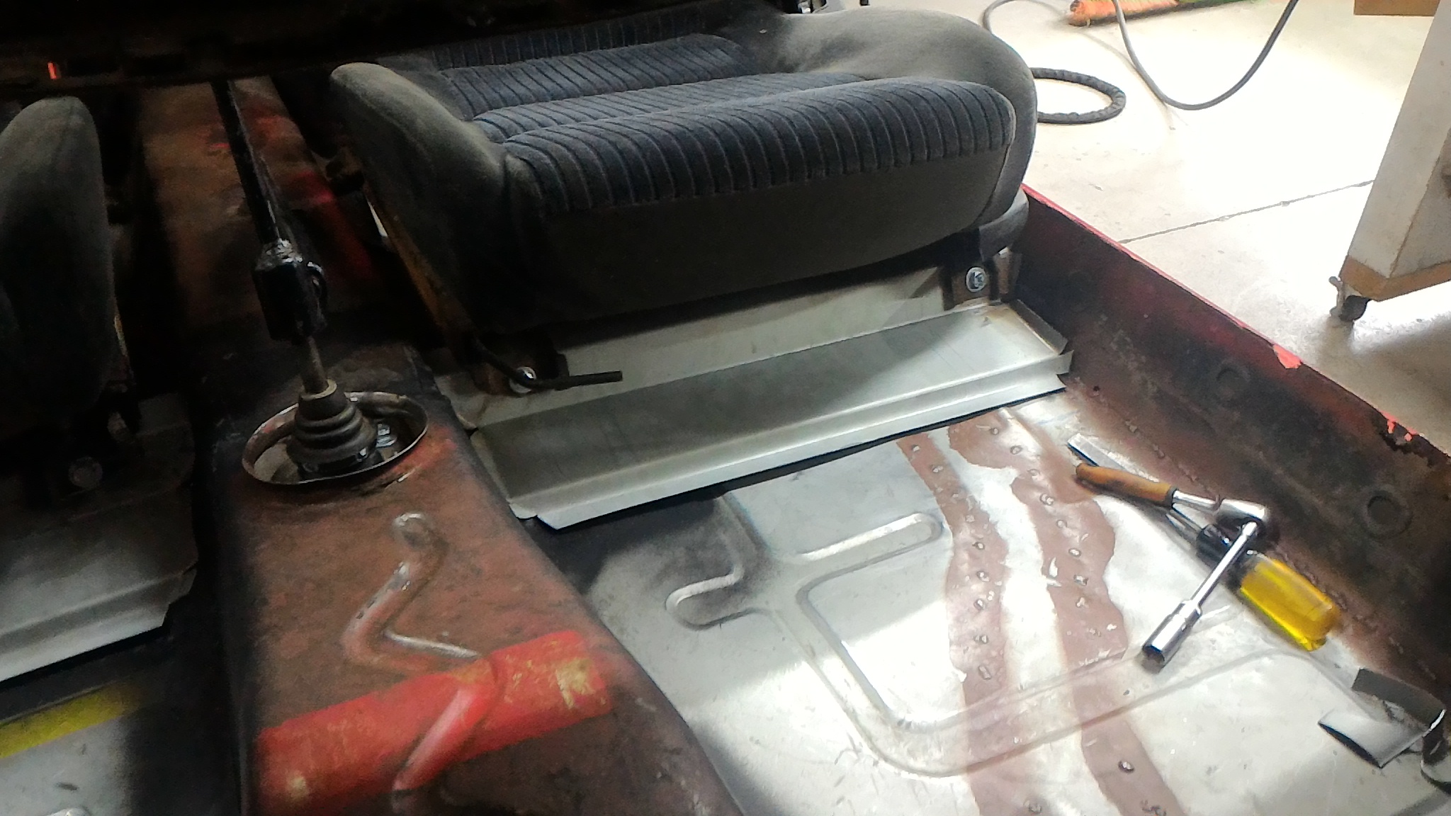
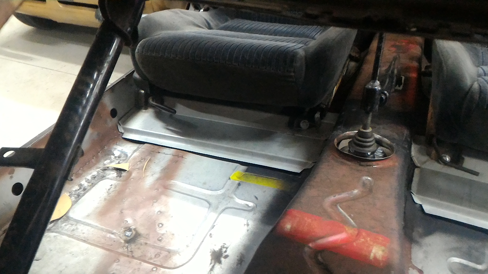
Continuing the floor themed fabrication work the next job was to make up some seat boxes to replace the ones that were torn out. I wanted them to do a couple of things. Firstly they needed to tie the tunnel brace to the sill as the stock boxes did, as well as fitting the honda seats as low as possible and still giving the full range of movement. Initially I made up a cardboard template before transferring it to steel. We folded the basic profile up on a big sheet metal brake at a local bus company's workshop before bringing it home and I fettled up the side profiles to fit the tunnel and inner sill as closely as possible. Doubler plates were drilled, tapped, and had captive nuts welded on before being plug welded to the inside of each box. While I was at it I made up the rear mounting posts as well but I can't find any photos of them right now. I might edit them in later on. Again, typical me, only the final product is shown. I'm leaving them loose at the moment until I can get a cert man to come and double check them to make sure they're up to scratch before I weld them in.
-
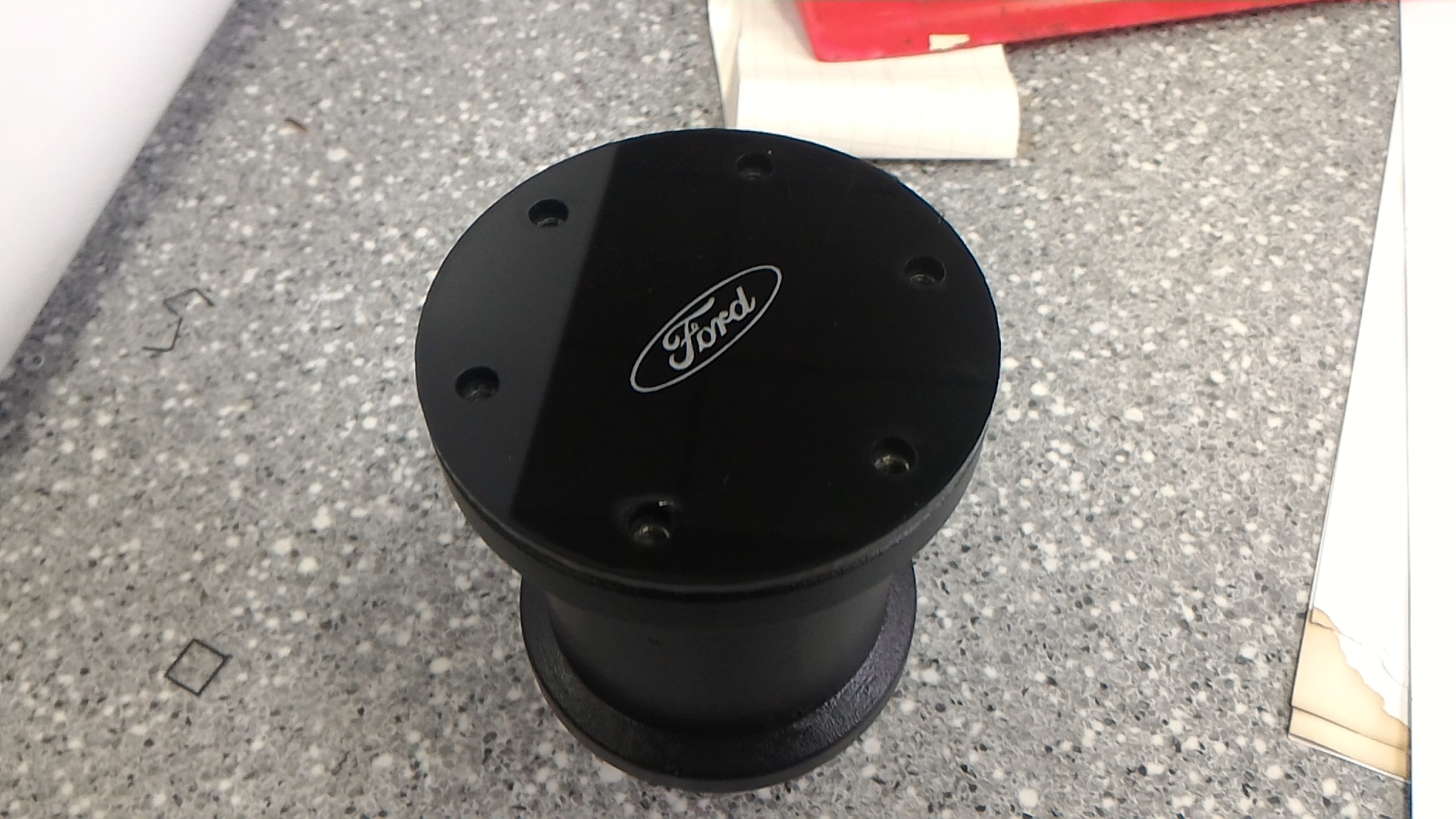
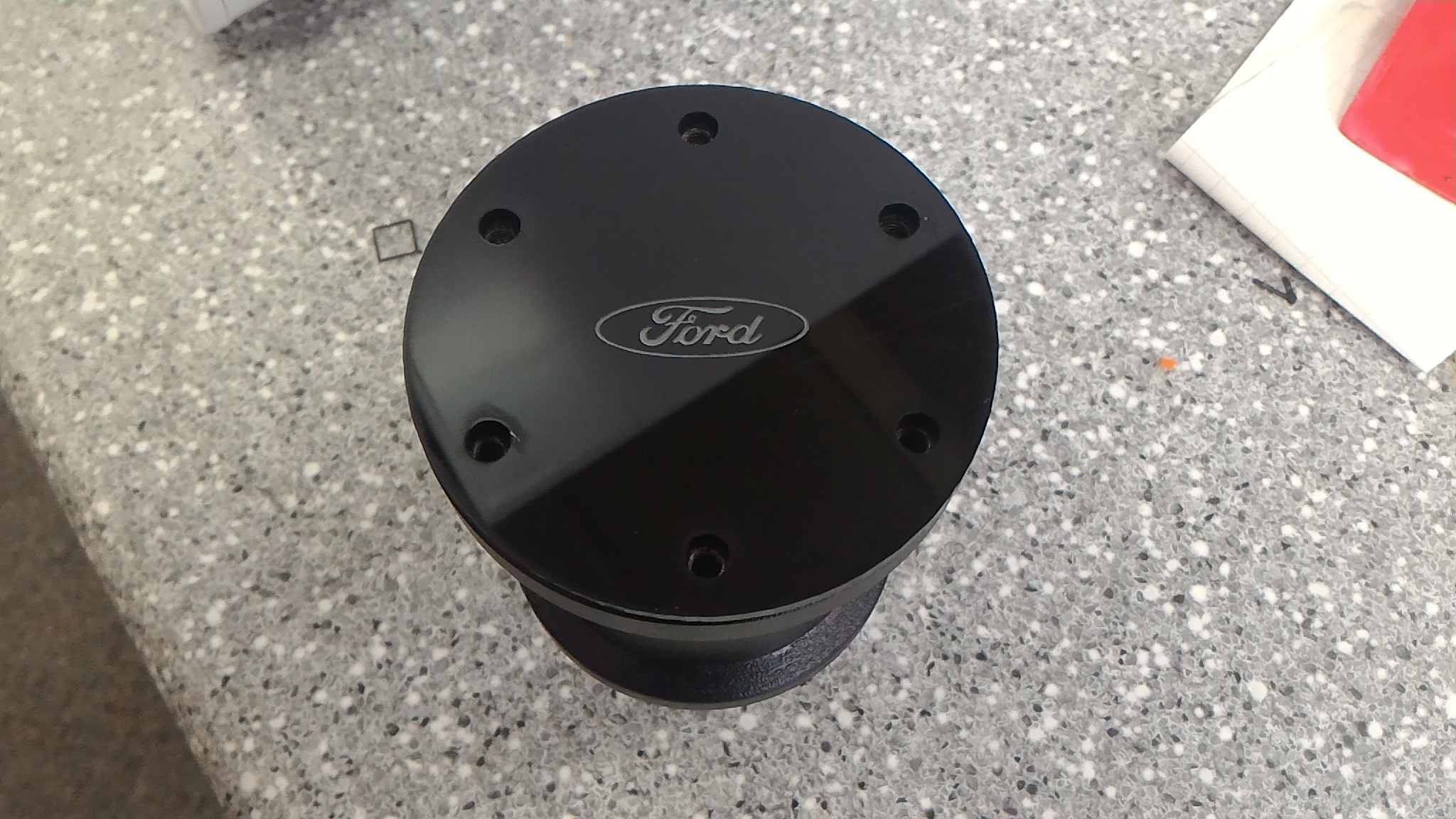
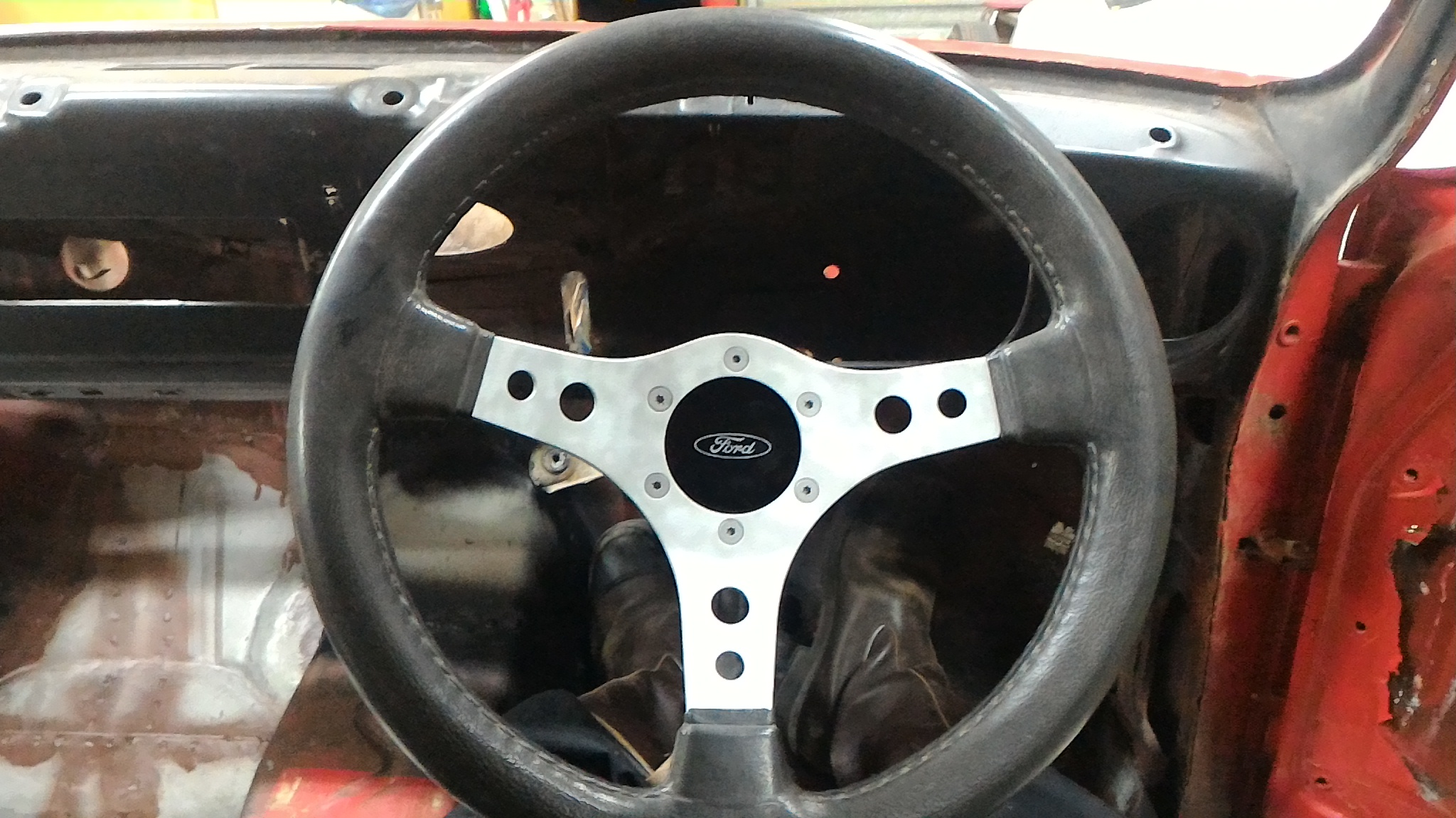
Got bored at school so I used the laser cutter to make up a nice center cap for the steering wheel I bought off a great bloke with a couple of escorts of his own. The boss and wheel had no center cap of their own and you could see right down to the main shaft nut. I though this was a nice neat solution.
-
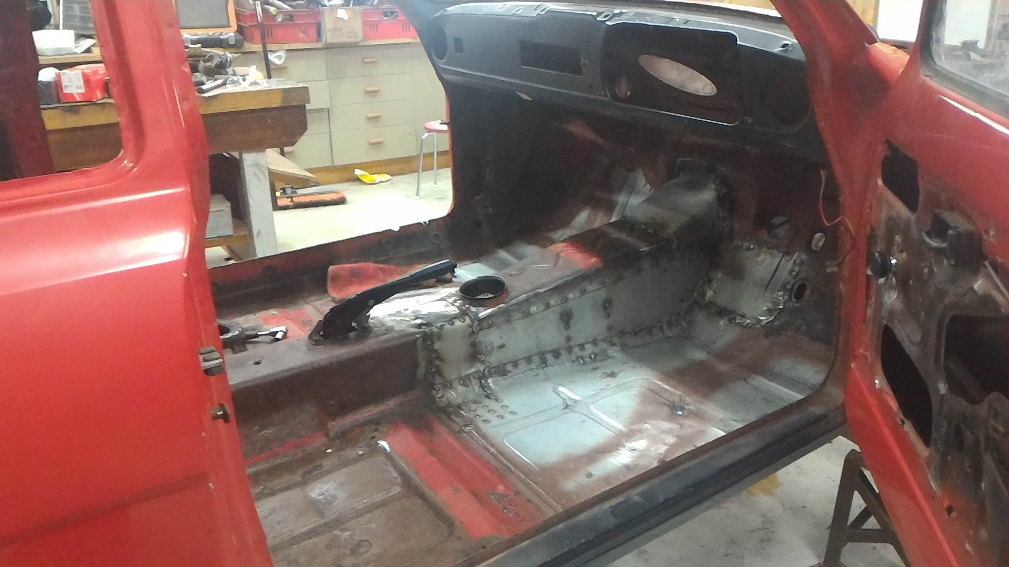
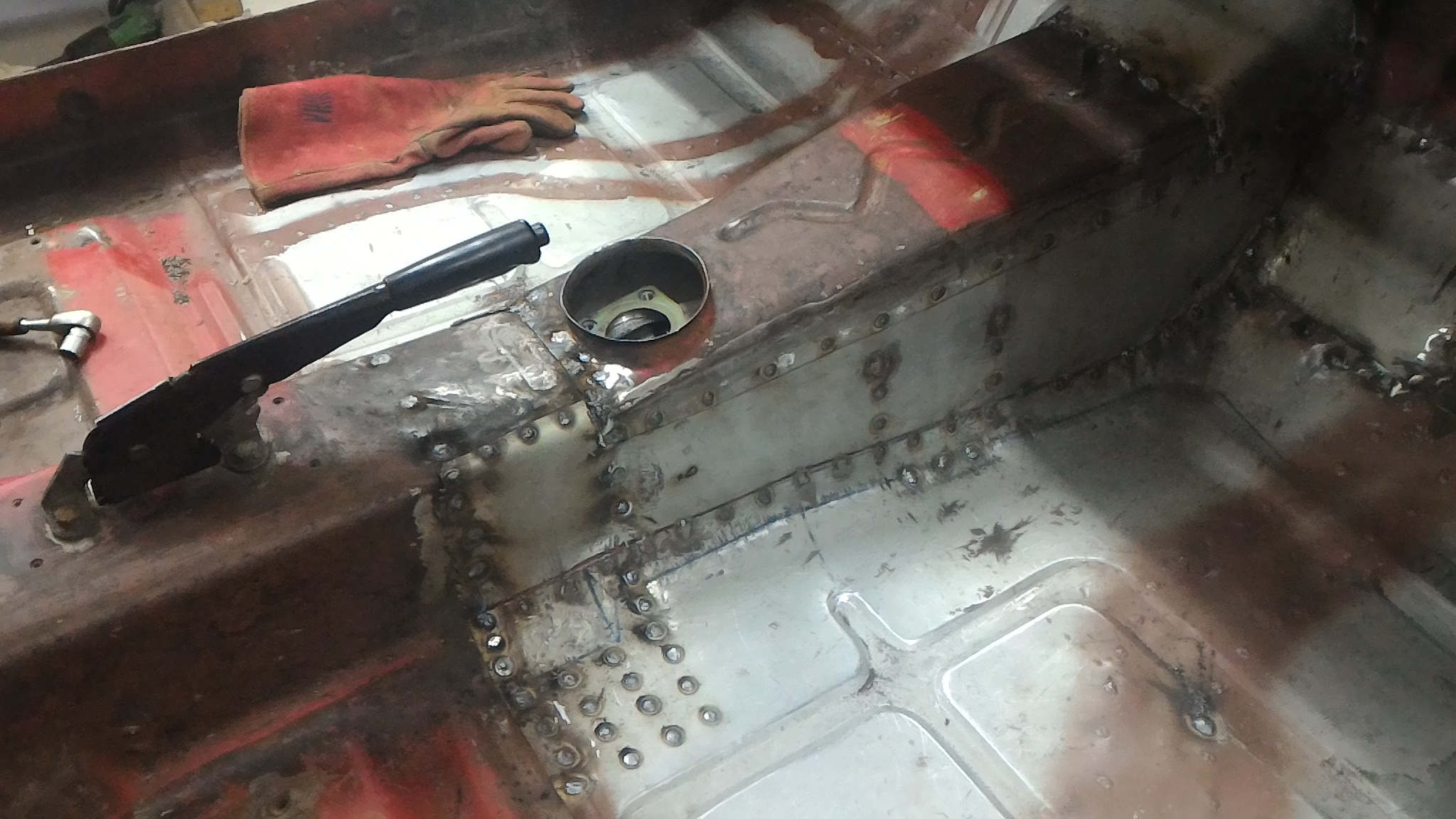
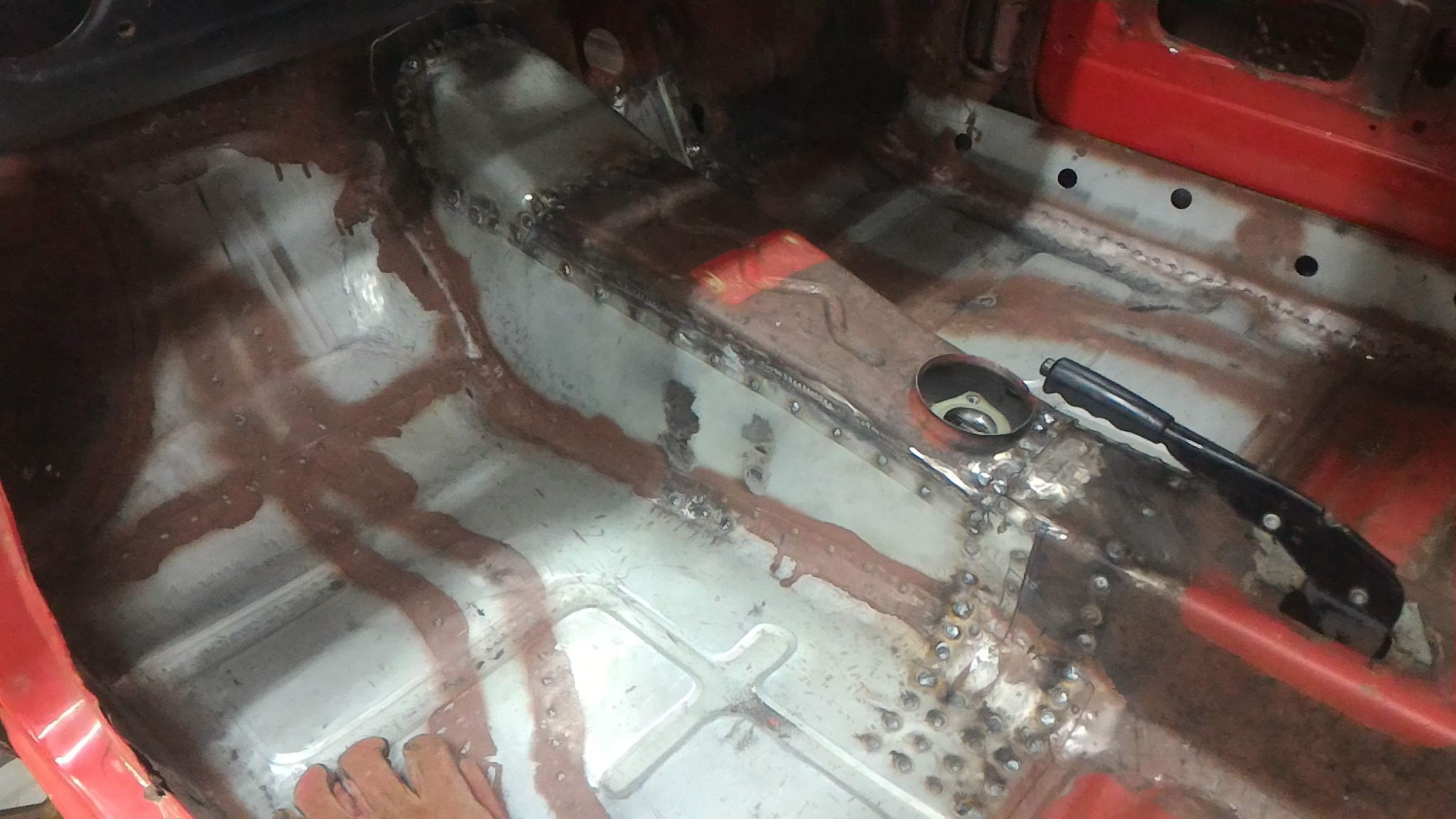
Finally we're back into the fabrication work This time it was all my work. Again I didn't take many photos of the process unfortunately but the results got documented well. Firstly I welded in a new tunnel side for the drivers side. Then I tacked in the floor pan to the new steel, and fully plugged it in. Once that was done I replaced some steel on the edges of the tunnel top to give me some more space meat to weld it back in and then did exactly that. Then it was a matter of making a covering panel for the gap opened up at the front of the tunnel and putting that in, before modifying the tunnel brace to make it fit in the more rearward position required by the longer gearbox and welding that in too. You can see the huge number of plug welds on that brace alone which explains why this was a fair bit of work all at once. At the same time I remounted the gearbox mounts in the new location (as you can see from the welds about halfway down the side of the tunnel) and fabbed some gearbox mount spacers to drop the box down the right amount to keep it all in the right spot. Unfortunately this is the only photo I took of it but use your imagination. The square plates blank off the ends of the square tubing and the bits of tube are welded into the holes to form crush tubed for the bolts to pass through. Trust me when I say the came up pretty neat.
-
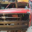
It was also about now that I splurged for my birthday and bought a brand new repro grill with the FORD lettering in the center from the UK. Considering the amount I ended up paying for it I wasn't too happy with the quality of the finish (the silver "paint" is just very poorly cut decals) but it should come up pretty good with a lick of paint. I much prefer this style of grill but they're rare as rocking horse shit to find and the guys that do have them never want to sell so a brand new one it had to be.