Hi Guys, cool forum! thought id post my project thread over here. Im an Admin over at xfalcon.com...
anyways, here goes
The build plan:
XF Twin turbo
Twin KKR 330 turbochargers (until they die then a pair of GT28RS turbo's)
As much power as i can get on 1bar of boost, (this is all im planning to run)
Gas research 480CFM carb
90L APA tank
3/8 twin LPG lines to twin VFF30 lockoff to two B2 convertors
Twin tank outlets incorporating a Duo Valve
Home made manifolds
Twin 2.5" exhaust mandrel bent system
custom inlet Plenum with front mounted Throttle body
250 xflow with hemi rods, ACL pistons cam and lots of headwork
6 coils in wastespark, based around MSnSextra, using EF 36-1 crank trigger wheel on balancer and homemade coil ignitiors
A decent restoration of the body
Ford focus Electric orange 2k paint
C9 transmission with TCE 2800 Stall
3.54 Jag Power lock diff and IRS
Aluminium Radiator
330mm front discs with PBR twin spot callipers
28mm front sway bar
Airide Shockwave air suspension
Accuair Ride height control
home made tailshaft loop
homemade oil air seperator
Steering conversion to AU falcon rack and pinion
EL/AU steering column
Custom engine mounts
Changes to lower control arms and front suspension
Dynamat inside
Redone interior in beige
Whatever else tickles my fancy during the build (depending on what i can afford)
Basically, I want to either do, and be involved with every single aspect of the build, and hopefully my trials and tribulations will help others with there own projects. Any feedback is welcomed, especially if im doing something you think could be done in a better way. I dont earn lots of money, so just about everything has to be done by me lol but thats where the fun is!
First job on the agenda, strip it to a bare shell. The plan is basically to get the drivetrain sorted, mount everything in the enginebay the way i want it, make all the intercooler pipework, bracketry, and weld in decent fixing points for the LPG convertors, Intercooler, catch can and all the other stuff that needs to go in there. This way, i can prep the shell for paint when done, and get the shell sprayed and be able to bolt everything straight in with less chance of scratcing the new paint. Theres also nothing worse than drilling holes to mount stuff after youve painted things, and have the metal filings accumulate in nooks crannies and and go rusty!
Rust isnt to bad, both doglegs behind the rear doors, and some new steel needed in the wheel arch areas, the plenum chamber below the windscreen has also suffered some of the cancer (try finding an x series thats perfectly clean in that area!) but its all pretty easy to get to thanks to the removal of the dash and pedal box assembly.
I did start on a few rust repairs, as i got sick of working on mechanicals, but have decided not to touch the body until ive finished the stuff under the bonnet
A general run down of the progress so far:
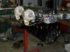
The engine will be the old Faithful 250 crossflow ford six like the last car, they respond very well to boost and make bagfuls of torque. people always ask me why i dont just go a later model OHC engine, I dunno, i like the simplicity of the crossflow, it will also be a lot more fun wasting a few newer cars with my old tractor motor!
Ill be using two turbo's, which are KKR330's from http://www.otomoto.com.au. I first found out about these little turbo's when i was googling for something, and came across http://www.ls1turbo.com.au they run a pair of these suckers on there GENTT turbo kits with great success. Aptly named kkr330, they flow aproxamatly 330hp each at full pelt. Rear housings are .86, front housing isnt advertised, but is similar in size to a GT28RS. they cost $700 each, use internal gates, with an optional 3 bolt dump flange that is removable. Stock wastegate springs are 6 to 7psi and have adjustable actuator rods, They also carry a T28 flange.
here you can see the removable dump flange
So, I had the turbo's, Now i had to get them hung on the side of the head!
Id never made manifolds before, so it was all new to me. First desicion was what material to use. this was a no brainer, Steam pipe, its cheap, easy to weld, and very very tough, which is a very important asset for something that is exposed to lots of heat cycling, Did i mention its also cheap? At $6 a bend, you cant go wrong!
The prerequisites for the manifolds were, compact, simple to make, and easy to package. Packaging took precedence over outright power, I wasn't interested in tuned length runners, and tricky merge collectors, remember, im only dealing with 3 pipes per turbo. At the same time, i didnt want a ****ty old log style manifold, I needed something in between **** and Great
First Cab of the rank was the head flanges, these i had to get laser cut. I went with 12mm thick mild steel, this way they were less prone to warping. I got a gasket, took it to my local sheet metal place, and said, copy this in 12mm Twice
next up i had to make the turbo 4 bolt flanges. these were easy enough to do myself, bought some 12mm thick mild steel flat bar, and went crazy with drills files grinder and hacksaw. now i could begin building the manifolds.
In total there are 4 90deg bends per manifold, the middle runner ends up being a straight peice of pipe, Here you can see how ive merged the pipes
They turned out quite well. As usual the second manifold turned out better than the first lol (remember, i had to make two)
here they are mounted up to the engine, i have both flanges angled so the snout of each turbo is angled slightly to the drivers side, and up towards the bonnet a tad, this allows adequate clearance for the rear turbo's intake pipe, front turbo's dump pipe. Its all a balancing act between providing adequate clearence with all things in the way, and keeping the design simple and unrestrictive, i was stoked!
The manifolds need cleaning up, and coating, they should look a million bucks when done!
Next up, I needed to sort out what i was doing to the dumps. As mentioned earlier in the peice, the KKR330 has a dump flange, thats removable, it carries a 3 bolt flange for the dump pipe. This wasnt going to work for me, as the flange took too much room away, and i wanted something less restrictive, so i got two flange plates made, in 12mm mild steel, Cost $30 each
Unfortunatly the KKR turbo's have a slightly differnt bolt pattern to regular T28's, and otomoto dont have gaskets, so after a bit of head scratching, i realised i could use T28 stainless gaskets, with a slight modification
Next thing to do was decide on what to do for the water lines. I could use steel bundy tube with flared ends, or olives, or use flexable stuff. Some people use rubber heater hose with barb ends screwed into the turbo, but this is a sure fire way of losing your coolant down the track, as the rubber goes hard from the heat put out from the turbine house, it splits off. I ended up using some heat and pressure rated hose, similar to hydraulic hose, but better for this particular application. First i had to buy some fittings to screw into the turbo's. these little fittings have a nice rubber backed sealing washer.
then i got some hoses made up. Im plugging into the water lines on the passenger side of the Block. The late EFI 250 engine has an alloy junction in the heater line, with two fittings in the top which are used for eitehr pollution or ventilation purposes. Usually they have vacuum thermo switch's screwed in. I wont be using these, so they get binned, the turbo water lines screw straight on with an adapter. The water then pass's through the turbo cores, and will return straight into the radiator end tank.
heres the hoses made up, two in two out. Note, on two hoses there are no fittings on one end. These will go straight into the the radiator end tank, i still havent ordered a aluminium radiator yet, so the hoses will be left with no fittings until i get a radiator sitting in place, this way i can cut them to the correct length.
The fittings are hydraulic spec, and were crimped on by my local hydraulic place
I got sick of welding and grinding, so decided to attack something else.
Im using a gas research carb, which i aquired off Cal, it used to live on his turbo XE, so the benefit here is, its been tuned for a turbocharged ford six, which should make things a hell of a lot easier for me, with only fine tuning to do (hopefully). Twin B2's will also be used.
These are mounted on a neat little Bracket, but for clearance ill have to rework it a little
This is where they will be mounted, Its a good position, low, hidden and resonably safe in the case of an accident (behind the shock tower) Cal had them mounted here in his XE. They wont fit without a few bracket modifications, The XE falcon has a lot more room here than the XF does, mainly because they have a different firewall. The XE uses a smaller ventilation and airconditioning assembly
For ignition control im using Megasquirt, with the MSnSextra code. Ill be using a 36-1 crank trigger wheel on the back of the harmonic balancer. I sourced a 36-1 trigger wheel of a very good friend by the name of Gary (Xdee), this guy has helped me out with so much stuff, for little in return, Top Bloke!
The plan is to run 6 coils, one per plug and do away with the dizzy. Megasquirt needs a few modifications to do this because Im using my megasquirt V2.2, which i built a few years ago for the first project.
The Gas research Carby has a TPS style shaft, which is great. I sourced a TPS of a throttle body from an EL falcon, and made a spacer to allow it to screw onto the side. The TPS will be used for datalogging, and possibly down the track a Gas research CTS feedback ECU, which use's an oxygen sensor to hold the mixtures in closed loop at cruise.
The CTS unit works by enriching the mixture at low load/light throttle applications. You basically need to lean of the cruise circuit by altering the mixtures on the gas carb. A PWM 2 wire Valve is fitted between the convertors secondry circuit, and a hose is run from this to a suitable position on the throttle. the CTS unit will cut in and supply more LPG to keep the mixtures hovering around stoicmetric in closed loop while cruise. When you stab the throttle it senses the quick movment of the TPS and injects a little more gas for acceleration enrichment.
Heres a Megasquirt i prepared earlier
In the pictures below ive modified the megasquirt to include spare outputs, Fans, coil driver transistors for the LS1 coils etc, Ive run a new cable with a DB15 for all the extra stuff as ive run out of pins on the DB37
This also includes a VR conditioning circuit to condition the signal from the ford EDIS VR sensor. The sensor has to sit around 1mm from the teeth, and the air gap is critical. The circuit conditions the signal and converts it from a sinewave to a 5V square wave so megasquirt can process it, heres the circuit diagram as shown in the MSnSextra manual
the edis wheel fits the harmonic balancer perfectly, or rather, it will when its machined down, a bit of alloy needs to be trimmed off the fords timing cover, but apart from that it all fits in like factory, the tricky bit will be mounting the sensor in the correct location. My plan here is to use a block of aluminium, cut and file it to shape, drill and tap threads for the sensor, then weld it onto the timing cover.
One issue so far, I dropped the harmonic balancer off to the machinist to machine it for the trigger wheel, he did this, but broke the trigger wheel pressing it on. it seems the wheel is pretty fragile, as its is made of a weird alloy like substance, but is ferrous.....it almost looks like a diecast material. Anyway, Gary has sourced me another, and this time it will press on properly...
heres a pic of the trigger wheel and sensor
and here it is with the harmonic balancer
the balancer only needs light maching to get the trigger wheel sitting properly, heres what it looks like before machining.
It sits snug over the seal surface, and needs about 8mm machined in towards the pulleys, and then it can be pressed on. the timing cover has a nice cavity slightly larger than the diameter of the trigger wheel, and only needs the three ribs removed, or ground back for clearance
Now that i had decided to go to all this effort, i wondered what i should do to the dizzy, as its pretty much redundant. It drives the oil pump, via the cam gear, so i couldnt remove the dizzy entirely, so i got thinking.
E series falcons that ran coil packs like the EF have replaced the dizzy with some kind of cam angle sensor, maybe i could use that? After all, Later model OHC engines share the same basic architecture as there older brother 250 engines. And again, Gary came to my rescue, (He's a champion) he had something even better! AU falcons have a dummy shaft oil pump drive in the dizzy location, without a cam sensor built in, so it is a lot less bulky. AU cam sensors are fitted into the timing cover, and seeing as i dont need cam phasing (6 coils in wastespark style) this would fit the bill.
This is how it looks after i made a few minor modifications. the first modification was to remove the AU gear, and replace it with the XF one, I used an XF distributor for a guide for correct height. The critical dimension is the distance between the plugs base, where it meets the block, to the centre of the gear, these need to be spot on. The other issue was, the Milled hex drive up the middle of the shaft. It wasnt as deep as the XF dizzy, which meant the AU drive wouldnt slide right home, which left a 2.5mm gap. this was rectified by simple removing the hex drive from the engine and filing 2.5mm off the end. the overall length of the bottom part of the shaft, below the gear was also around 2mm longer than an XF distributor, Which i dont think effects anything, it doesnt foul, so its probably okay, i decided to shorten it that little bit just in case
Heres a picture comparing the three
from left to right:
Standard AU Modified AU to fit 250 Standard 250 distributor
I decided to get cracking on the intake side of things. The original plan was to use a Cain four barrell manifold, with a GRA adapter. I had a GRA to weber adapter that Cal was no longer using, so after a bit of rooting around i made a 16mm thick alloy adapter plate. in the end i decided i wasn't 100% happy with the arrangment, and decided to make a decent intake plenum, which im currently still working on.
heres a few pics of the original setup
I decided i wanted something a little more efficent and power productive, so i decided to make a plenum. Nothing to big. I started by cutting out some 5mm aluminium sheet using cardboard templates
For the throttle mounting, i cut the Flange from the gas research weber adapter, seem's a waste, but it already had the studs fitted, and had a nice angle milled onto it to allow the throttle body to face down a tad, it would also save me heaps of time on cutting out and milling up another
here ive dummied it up to get an idea of what it will look like
a good tip when cutting aluminium, if using a cutting disc or drop saw, candle wax will stop the disc from bogging up. The aluminium tends to melt and clog the cutter, making a real messy cut.
and the olbligatory plates bought by a group of xfalcon friends for my birthday!!