

KLR250
-
Posts
103 -
Joined
-
Last visited
Everything posted by KLR250
-
Firewall work today, filled all unwanted holes, next step is to remove the blower fan hump and weld in some sheet. after than i wanted to weld the brake master cylinder reinforcing plate to the firewall and blend it in, much like glenn did to sas01. Im having trouble making a descion on the clutch cable tube that pokes through the firewall, Im using a C9 auto for the most part, but Im considering putting a manual pedal box in so i can swap to T5 for dyno days n such....its so damn ugly though and i feel like cutting it off and welding it up I also cut of those studs that poke through the firewall and welded up the holes.
-
More Pictures Im not a very good welder when it comes to this thin stuff, this is about 250 spot welds lol had the wire speed way down, much less to grind this time round heres some pics of the other side pretty much ready for filler I was able to weld the panel right around the strengthening gusset which was good
-
Been busy in the engine bay today, pretty tedious, but im getting there Boxed up the sway bar mount, filled front crossmember holes, and have made some cover plates to cover the uglyness on the front towers. first i made a template from cardboard then i cut the peices out of .8mm sheet this will be welded on and smoothed into the towers, Ive cut access holes to get to the control arm bolts welded crossmember Boxed sway bar mounts. I forgot to take pics of what i did here, basically i welded nuts inside so bolts will hold the sway bar brackets from underneath Ill have a lot more pics tommorrow night, plates will be welded in, Ill have that surface rust blasted off so i can start on some filler and paint
-
Pretty much coming to the end of the underbody painting phase now thank god. Tonight i applied underbody deadner to the wheel archs and the outer floor pans (between the sill and chassis rail) I bought a gun to do this today, $49, worked really well Its so hard taking photo's of black underbodys, you cant seem to get good pictures I will have some engine bay pictures soon all going to plan
-
Got a coat of black down tonight, well the back half of the car anyway, its pretty thin in spots as its only the first coat, but its coming up pretty good i reckon
-
Epoxy is on and looking nice!
-
As mentioned in a previous post, i had removed the gearbox. Last night i started stripping the engine bay, I love working on this thing, as its in such good condition. Tonight i started degreasing the forward floor pans and tunnell, obviously these have the most muck on them. I decided to use the air compressor and degreasing gun, i turned the pressure up to 100psi, only supposed to have 60psi max, but the extra pressure really moved grease and muck, Tommorrow is the soap wash with scrubbing brush's, should come up really good. Anyone doing this sorta of work, Buy your self toilet brush's, there awsome for this kind of work!! anyway, some boring pics and the pile of stuff i wont be using
-
-
ahh, been busy! Still scotch briting and cleaning the underbody, Mongrel job, but coming up great. Id like to Thank glenn (xm221) for sending me a brand new spot weld drill bit, why ive been using normal drill bits all these year is beyond me, this thing halves the time and you dont end up with a million holes to plug weld, anyways, what a dumb arse for not getting one ages ago! Im using it to remove unwanted bits n peices atm. Because its going to be a straight LPG car The petrol tank is obviously removed, so im underneath removing all the petrol tank mounting brackets, exhaust heatsheild and generally just tidying it up before i lay on the epoxy primer. I really want to piss the spare tyre tub off, as i cant stand it, the fact it sits below and can be seen, it just looks ugly, so im trying to come up with a plan to remove it, and replace it with a rail similar to the passenger side. Easier said than done, its a structural peice, and there seems to be no obvious way of removing it without some major fabrication. At the moment im leaning towards just cutting the bottom off and making a flat bottom, at least it wont be seen from behind or while standing behind the car. After spending ages cleaning underneath Im thinking of painting the floor pan a differnt colour. I bought 4L of GMH satin black, same stuff they used in the engine bays of the early holdens, But now im thinking of going freighter silver, which incidently is the same colour i used on the AU Racecar roll cage. The reason im thinking of going this way is because i think a lighter colour underneath may look a little nicer than just a black, and highlight the detailed under carrige, i.e control arms, diff, gearbox etc. Talking to some mates about it, they all agreed that it will look crap in a short period of time, from rocks and road debris, But i came to the conclusion that it shouldnt be a problem, If you look under the car now its really clean, bugger all in the way of paint damage and stone chips, and its all original paint, fromt he factory in 1986! I think the key is to paint between the rails with just the 2k silver, and on the outside of the rails & in the wheel tubs use the underbody stone guard/deadner, as this is where all the stones and stuff get thrown, between the rails is immaculate....anyway, ill take a few pics, not much to see atm
-
So much for no rust!! Heres what happens when muck gets behind the front guard...lots of you would already know. you can start to worry when the 2 10mm bolts underneath just spin around and you can hear crunching noises heres the replacment panel Considering that this thing was one owner and always garaged it goes to show just how important it is to remove your guards occasionally and clean them out
-
been busy getting covered in sh1t today, ive used degreaser and scrubbing brush's, then a rinse, ive got half the floor done (back half) front half tommorrow night, then its soap wash. Considering this is only degreaser its coming up really nice bits to get zinc plated, they will get a gold passivate to bring them back to factory
-
heres a before picture before i start prepping the floor pan, still gotta rip out the hand brake cables, brake line, exhaust, trans. This weekend ill only be working on the rear section. Floor pan is very clean, can still see most of the factory grey paint
-
heres my pipe bender, its actually the best one ive owned, and bends 1/4 just as good as 3/8 line heres how i did the water returns, both into a 9/16 JIC tee, then hooked to the braided line up to the banjo on the thermostat neck heres the 1/4 oil feeds, i managed to get the bends really tight, if anyone plans on doing there own hardlines, make sure you measure and mark your pipes, i kinda just made one, then duplicated it, but didnt really mark anything and did it by eye, very tricky, and a pain in the arse. Really not an issue if your running one turbo, as you dont have to make things symetrical heres the banjo bolt, this started out as 18 x 1.5mm, i had to get it machined down on the thread, then i tap'd a bsp thread on it, and then tap the thermostat housing to BSPP, The bolt had plenty of meat on it, so it was all good then this is hooked up to the banjo and earls line theres heaps more plumbing to come, Mainly LPG balance lines, liquid lines etc, then the engine comes off the engine stand and gets bolted to the C9 so i can make some 3/8 stainless tranny lines, which i want to get hugging the trans/block nice and tight. The trans hard lines will end up near where the aircon/alt Bracket bolt to the block, These then gets nipples on the ends to transition into more -6 earls lines. Trans cooler and engine oil coolers are going behind the front bumper in front of the tyre, but as close as possible to the bumper. Holes will be cut into the bumper, It will be subtle, and hopefully look kinda cool
-
bent the original dipstick tube to get it sitting in the right spot through the plenum runners, but it looked crap, so i made a new tube from stainless. This is where im mounting my convertors, Ill be mounting them side by side under the plenum, and using the fuel pump blockoff bolts as the main attaching point for the bracket, and also a smalll strap to one of the lower plenum bolts, ill have some pics soon of them mounted. Basically its the 2 B2's with the 2 VFF30's mounted directly underneath, keeps it all hidden quite well, and resonably close to the throttle body, and also in the perfect position for the water plumbing modded sump Also, you cant see in this pic, but its been dented slightly in 6 spots to clear the big ends as they swing around More pics to come soon, My LS1 coils are now setup on a bracket, should look trick still waiting on my dash 10 nipples for the oil drains stripped the paint off the block and redid it lol, i couldnt look at the silver any longer
-
made some flexable lines up for the water feeds and return back to the thermostat housing. Also had to tap the thread in the thermostat neck to a parrallel thread, as there a tapered thread, which is no good for a banjo fitting. Also got the banjo bolt turned down to the correct thread, it was 18mm x 1.5mm originally, got it turned down to the correct thread to match the thermostat neck... pretty boring, but another job done I really got to get some alloy spannersfor doing up earls fittings, there immposible to do up without scratching them using normal spanners. Next up is the oil drains, just waiting on some -10 weld on nipples, then its convertor mounting and rigging up balance lines and associated gear
-
Okay, as mentioned earlier, Ive re-routed the water outlets to underneath the manifolds, as its much tidier. Im teeing the outlets together with a -6 T fitting, Just got to get the rest of the pipes flared tommorrow. In this shot you can see the rear water outlet from the block. From this it will be joined to the stainless tube via a -6 speedflow line, same for the front outlet. Hopefully my speedflow fittings and hose arrives this week. here you can see how ive bent the tube through the manifolds. The rear tube goes underneath all the way to the front where the T will be off the front turbocharger. From the T it will be speedlow -6 fittings and line to the thermostat neck. This then means the lines wont be rigid and things can move a little bit as things heat up You can see the line from the rear turbo here....
-
I re-routed the water lines, made new ones. It was getting to cluttered above the manifolds, so ive run them below the manifold. Ordered some braided line and -6 earls fittings to go between the block and the turbo's to allow for thermal expansion of the turbo's and manifolds. Doing away with the double banjo bolt on the thermostat neck as im tee'ing the water outlets together underneath
-
Finished the oil lines, Ive used 1/4 stainless tube. I managed to get hold of some banjo fittings with the appropriate ends, -4 for the oil lines and -6 for the water. they came from Japan Via ebay, cost me about $80 for all of them, in Chrome, and took 4 days to get here, Better than the companies ive been dealing with in oz, I just couldnt seem to find exactly what i needed in catalogues. The oil comes from the sender outlet in the block, to which ive screwed an aluminium fitting which are normally used for multiple airline couplings. Its the tidiest fitting i was able to find, as i didnt want tee fittings. Ive run an oil line for each turbo from the block heres some pics, nothing exciting, but ill post em up anyways
-
My new Gun arrived!! Cant wait to test it out Ive been working on the engine lately, bending up stainless oil and water supply lines, as soon as the dash 4 and dash 6 banjo fittings arrive ill be able to finish it off. Head still has to be machined for the roller rockers and guide plates, bottom end has been freshened up. Block is ready for the electric orange, but it been to damn cold, im thinking of buying a gas heater. Ive rekitted the VFF30 lockoffs and started on another twin B2 bracket, my mounting of the B2's and VFF30's is turning out really good, and it all will be pretty much hidden away anyway, im about two weeks away for a picture update, providing some parts arrive. At the start of my thread id gotten some flexable water lines made up, but i hated them, they looked shithouse. Plan B was to go for some braided line, but its still to messy, it needs strapping up so it doesnt rub on things, which isnt really an issue with 1 turbo, but with two turbo's id have hoses every where. So i went with stainless tube with flare nuts and flared ends, and the stainless polish's up like chrome, and once bent to shape it stays put. Ive tapped the water jacket on the driveres side for water feed to the turbo's, basically just drilled two holes and tapped 12mm x 1.5mm threads to accept some JIC 9/16 fittings, this really simplifies the water feeds. The oil is supplied via the sender fitting on the passenger side as per usual, but ive used an aluminium fitting that has 3 1/4 bsp threads, 2 for the turbo's and one for the sender, Ive been looking for ages for a fitting that looked nice, i didnt want adapters hanging off the block, this looks really good and will keep the lines tidy. I need to restrict the oil supply with 1.5mm holes, I can purchase banjo bolts with a 1.5mm hole
-
6L of electric orange, with heaps more gold pearl mixed in, Its a great colour. also got 6L of clear reducers hardeners and miscellaneous Im now 1k poorer lol, $1000 in a few tins, unbeleivable, dunno how people fork out for house of colour http://chemspec.co.za/metalux_range Id never heard of this stuff till recently, The original plan was ppg, but i would have been up to $1500+, so i thought fvck it, ill get protech then i was talked into this, the clear is mint apparently, was a bit dearer than protech, but the pearl should have a better kick Its made in souf efrica
-
My LS1 coils arrived finally, they came with the connectors to, which is good. currently making up an aluminium plate to bolt them to, which will be mounted on top of the rocker cover. Will Take some pics tommorrow These are great coils, and after some bench testing ive confirmed that one LED transistor on the megsquirt will easily trigger two coils. The internal ignitors are bloody awsome Im chasing up a mil spec bulkhead connector, This would make the efi/lpg wiring very tidy basically im making the ecu loom and want to have a bulkhead plug through the firewall the loom will have the 6 coils run through it, LPG wiring, sensors/trigger the works
-
Heres some pictures of my plenum bolted up
-
got wheels, 8" ones for the front are still a few days away check em out, the dish is more than i expected, they look great in the flesh
-
heres the runners welded up, ive bolted them to my scrap head ive smoothed 4 of the 6 port entries, takes ages
-
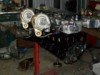
sorted out my power steering pump. Because ive opted to go with a straight runner intake manifold the stock pump will not fit. went to the wreckers, and sitting in the power steering pump pile, i found a pump with VL written on it in wrecker pen (its not VL, its VK or VH i think) thing is, its a V belt pump, i thought VLs ran those 4 or 5 rib belts. this pump is virtually identical to a ford pump, albeit with the resouvour removed. it has a screw in fitting for a remote resouvour best thing is, its a straight bolt on heres a pic of the VL one (if it is a VL one) and beside it is the ford one, removed from its resouvour (can someone spell that for me? lol) only thing that needs changing is the pulley size, holden one is much smaller, a ford pulley will go straight on it bolted straight up to XF bracket, even the high pressure hose screws in this is the magna pump i was playing with, but the holden one looks easier to work with and will work correctly with the ford steering box