

KLR250
-
Posts
103 -
Joined
-
Last visited
Everything posted by KLR250
-
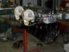
Plonked the motor in today to check clearence, everything is looking good. Clearence between the steering rack and sump is perfect. its just sitting in there atm so i can measure things, and work out how tall my engine mount brackets need to be, the motor will be coming forward just a smidge, only about 15mm anyways, some pics
-
Painted it the satin black i plan to use on the engine and alloy accesories, this colours gunna look nuts against the orange, actually makes the welds look nicer to So, things to do to finish it off, i have to drill 3 holes in the rear of it on each side, and make some load spreader plates to bolt it to the xmember. Make 2 small triangular gusetts from the back of the engine mountings just for good measure. Make the bracket that will bolt through the bottom of the factory xmember and will fold up around the rear side of the rack mountings to make it double shear, and weld on some tabs to utilise the additional X series engine mounting locations down below the engine mounts
-
Nearly finished the mounts and cradle, just a few re-enforcing gussets to weld on, and a few more mounting holes to drill in the cradle and i can send this off to get powder coated. Ill dummy the motor in and finish the upper mounting brackets before i get the thing coated. I welded nuts inside the mounting holes that get covered by the engine mounts, so with two of the holes the bolts go in from underneath Its taking so long because i had to keep measuring, tacking, removing and all the rest of it. Made a slight alteration to my mig torch today, best thing ive done, made so much differnce. I noticed the contact tip was a long way inside the gun, ive been told by numerous people that the contact tip should be flush with the end, or even protruding slightly, i shaved 3mm off the gas sheild, so the tip was flush and now my welds dont build up so much, its awsome welding is getting better, getting a bit to much spatter though, but there deep penetrating welds that look quite good i think seemed to have trouble making the welds look nice on the front face, need a different tecnique i think. there strong welds, just not as pretty as id like also welded on the boss's on the steering rack mounts, this will stiffen the area a bit more and give more support to the bolts
-
sorry for these boring updates guys, Im spending way to much time on these engine mounts....anyways, started boxing them in. Decided to box the underside to, and will weld a nut on the inside for the mounting plate like clint suggested, looks heaps nicer and will be tons stronger
-
getting started on the engine mounts today, cut the first peice out to get a few ideas on how its going to sit. The plan is to use the factory engine mountings that bolt to the block, instead of the factory rubber engine mount ill fab up a pair of brackets that bolt to the engine mounting brackets, these will then bolt through the bush
-
here it is bolted up should look factory once its all said and done
-
Cut out the bearing mount tonight from the AU Floor plate, made it look nice and welded it in, also welded nuts on the inside of the plate so i can bolt the thing on ffrom the engine bay, will look much neater than the self tapers they used from the factory. Good news is it all works!
-
Been working on the floor mount for the steering column bearing, Ive made this from 3mm and had to make it from 3 peices because theres a contour. I have to cut the bearing housing from the AU floor plate and weld it in. I opted to make a hybrid XF/AU floor plate because i always want the option of refitting the stock steering column if i have to. this simple looking peice took me ages to make, getting the holes right etc was a real pain in the arse. so, once i cut the bearing housing out of the AU floor plate and weld it in my floor plate the steering coulmun should bolt straight in and the steering shaft will bolt up.... If anything wears out down the track i can relace all this shit with standard bits from an AU
-
getting there slowly hopefully get started on my steering column floor plate today so i can attach an EL steering column to the rack, if i cbf
-
Decided to finish off my plenum. When i put it tgether i used thick walled alloy tube for the runners, So i could file down the welds and blend them in, so the runners and head flange looked like one peice. After many hours with my files and sand paper i had them knocked down and smooth. Heres the welds im talking about I used a really course file to knock the welds down, then stepped to a finer bastard, then finally sand paper. Its been a real bastard of a job, but it will be well worth it in the end. Im not wanting a polished finish, more a machined raw finish, so ive found using 240 grit wet n dry then green scotch brite, and finally grey scotch brite seems to yield the best results, You kind of make sure you always go in the same direction to give a kind of grain. Ive probably got another 4 or so hours to go in just getting out the imperfections in these pics #6 runner is starting to look the way i want it Id also like to thank don for his helpful tutorials and you tube Vids, real helpful, even though im not going to a polished finish your tips and tricks on dealing with alloy are real helpful Ive purchased one of these little suckers to weld underneath the plenum to serve as an over pressure releif valve, these are BOV's, but have a nice spring tension adjuster on the top, They have a 50mm piston, and should flow quite a bit. Ill be machining the bottom V band flange and welding the assembly on. Im hoping i can actually machine enough off the bottom of it to the point where the piston will actually sit flush with the plenum floor, we will see anyways, lots more other shit happening, but it will have to wait until i get the pictures of the camera
-
i got the tubes machined up for the engine mounts and picked em up yesterday, im going with old man emu bush's, apprently they dont break up easily.
-
before after
-
A bit of a boring update. Got my stub axles back yesterday, they came out really good. Can barely tell the steering arms have been shortened. Big thanks goes out to danny for the use of his reamer, It worked really well in the mill, perfect tapers. All up the guy charged me $60 to mill the tops, drill the holes, taper the holes, cut the ends of and linish the ends. The tierods had to be adjusted out to match up, about 24mm longer on the rack ends, Bump steer is getting to be less and less of a concern now, rough measurments show 160 thou toe out from my ideal ride height to the bump stop, and bugger all toe change on droop. This weekend Ill be finally making the bump steer guage so i can measure it properly. Steering ratio is 3 turns lock to lock
-
more slide shows
-
Im getting into doing these slide shows, I redid my recent one with better Titles and descriptions...I know its basically the same but i reckon there fun, i need to get some better software and take better pictures, im a really shit photographer. Great thing with the slide shows is you can show quite a lot in a short period of time, and it much easier to explain things
-
Cleaned up my good stub axles tonight, as im dropping them in to get milled down flat for the tie rod hole. I could do this with a grinder but i want to get it nice and flat and completly square. In the pic you can see the flat area where the tie rod nut would sit, Basically it will be put in an end mill and the flat area will continue up along the arm further. Im going to get the machine shop to drill the hole, Much easier for them to get it square, the guy also said he could put Dannys tapered reamer in the mill and do the taper, the mill can go down to 20rpm so it might be better doing that than wrecking my arms again there still aching. The practice stub axle i did has completly stuffed my arms, it took at least 20minutes to ream out by hand anyways, the pics Steering lock
-
Used Dannys reamer tonight, shifted the tierod position in 25mm, it now gets full lock with a much better ratio. This is just a trial run, ill make sure to get the hole centred on the good stub axles, It was a biatch to put into the drill press, i cracked the shits and drilled it whilst holding the stub axled in my hand lol. Next ones i do ill take them into town and get the top and bottom milled flat before i drill. I thought id lose heaps of ackerman, but i dont think this will be the case. One good side effect is the rack end ends up 1.2" longer (tie rod had to be unscrewed 1.2" to match the new position), and this has again reduced my bump steer. The other side effect is the rack ends end up on a 2deg forward angle when the wheels are straight ahead, this seems to have helped keep the ackermans satisfactory, as the increase in rack end angle means the stub axle spins faster as the wheel aproachs full lock... If i cut the steering stops off the radius rods i think i can get a tad more lock, dunno if its worth it. anyways, steering will be reponsive now, should be about the same as an AU, stub axle steering arms are approxamately the same length Remember, this is just a dry run, so it looks a bit dodgy, the proper stub axles will be done properly Once the good stubs are done ill cut the old hole off
-
did another slide show for the steering rack stuff so far...
-
Got both the rack ends shortened this week, bolted them up last night to check steering lock etc I dont quite get the maximum lock yet as i still have to shorten my steering arms on the stub axles, theres another 10mm before it hits the steering stop on the stub axle. Danny (Xdrift) has kindly lent me his 7deg reamer so i can ream out new tie rod holes. Initial bump steer measurments are no where near as bad as i thought they were going to be, from full droop through 4" of travel shows a maximum of 2.5mm toe change, but so far things look promising, as the actual area of travel you would be driving the car in wouldnt be to bad at all. This is with the stock lower control arms, so im pretty happy. Mind you, ive only done this with a tape measure, im going to set up a better measuring rig with a laser level
-
Okay, pressure washed the rack today, all the paint came off and it looked like brand new, Gary really looked after me on this one, its immaculate! For the first time ever my measurments were spot on with everything, this NEVER happens when i use a ruler or tape lol With the 6mm spacers i made between the rack and the cradle it fits beautifully Here you can see how well the steering shaft is poitioned, uni joint angle is minimal, there should be no bind whatsoever Height is spot on, tie rod angles look really good
-
Went down and picked my steering rack up from gary (XdEE) today, Thanks Gary It bolted up, and so far i reckon my measurments were pretty good, rack height seems ideal. Need to shorten the arms slightly and tap some thread Uni joint angle looks spot on to. Tie rod taper appears to be the same as X series which is handy. i didnt really clean anything, just bolted it up, Once i shorten the steering arms i can start on bump steer measurments
-
Ive had 0 Motorvation this weekend Pick up a steering Rack of gary next weekend all going to plan. Am about to start on my engine mountings, this is where i wouldnt mind some opinions. I want to fabricate something like this to weld onto my mounting plates and make something like this to bolt to the engine Id weld these things directly onto the engine mount plates which will utilise a urethane bush with a grade 8 bolt through it. is there any reason everyone puts the urethane mount on the engine, with the receiver on the chassis? i want the urethane mounting on the chassis with the receiver on the engine...get me?
-
Decided i had to tack it together so it was one unit, bit easier to work with, here it is
-
Just cut the drivers side mounting plate out, Ive run out of thin cutting discs, so im perservering with 2.5mm cutoff wheels, they suck Dummied in position view from under the car
-
i decided to dummy up my suspension to double check a few things. Because ive moved my bumpstop plates up they end up moving further out, so there is a concern the tyre may hit it. Looks like its all worked out, no clearence problems so far. The suspension will squash lower than this with the full weight of the motor and drivetrain all in all im pretty happy, im able to retain the factory bump stops, but still get it slammed, the factory stops will stop the shockwaves ever getting damaged,, added insurance, and the bump stop plates strengthen the front end by quite a lot being welded in on 3 sides. this picture shows the steering almost at full lock ( couldnt quite get the last bit as the trolley jack is in the way) One thing i definatly will do is alter the radius rod bushings, ill either replace them with a big rose jont and cross bolt them through the factory bracket, or buy the rrs bearing assembly's, as the bushings really put a lot of tension on suspension causing quite a bit of bind. Interestingly, the factory ball joints still have a fairbit more movment in them before they bind, they have a lot more travel than a lot of the aftermarket ball joints ive seen