
- Popular Post


MS51HT
-
Posts
75 -
Joined
-
Last visited
-
Days Won
6
Posts posted by MS51HT
-
-
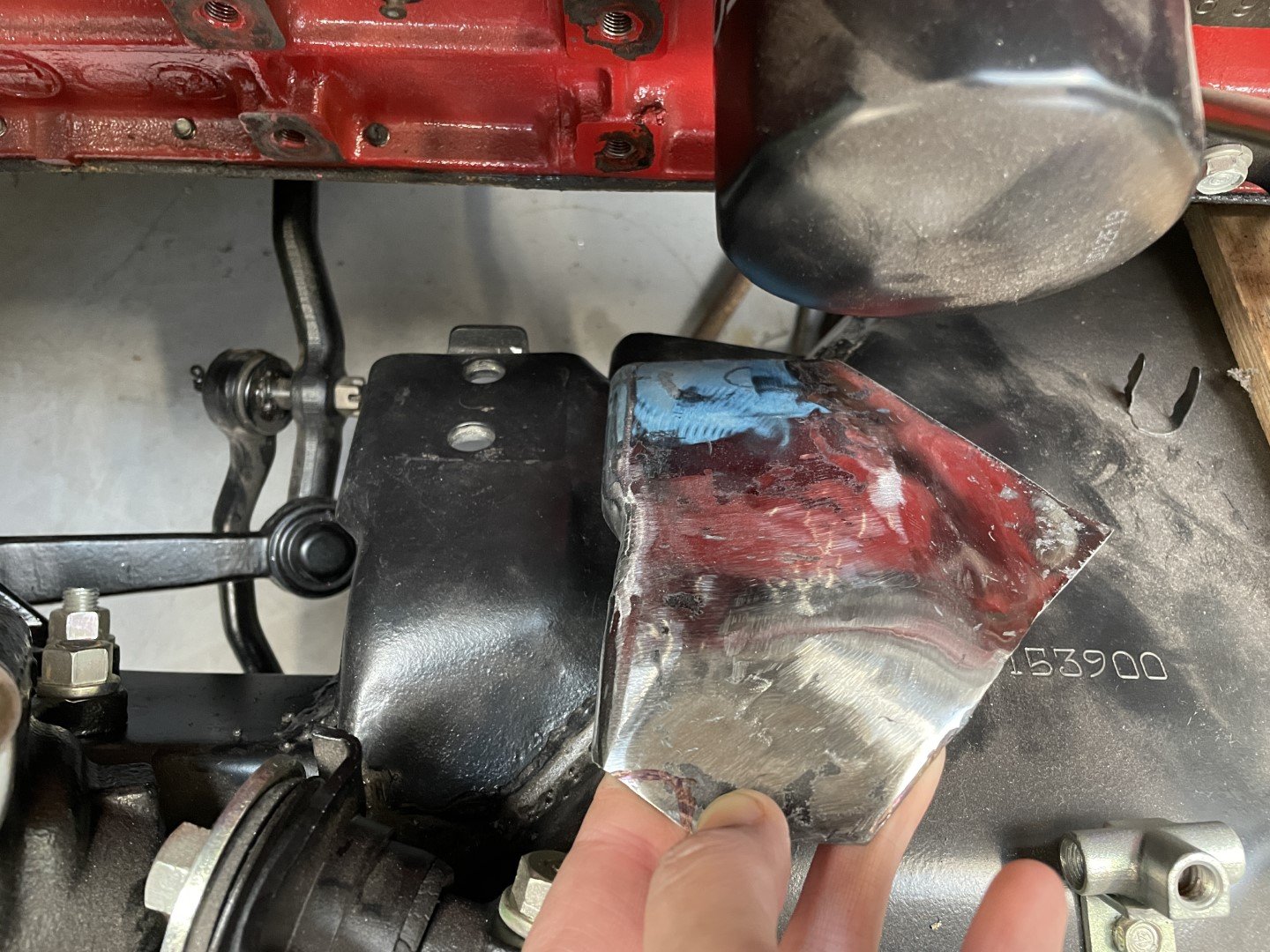
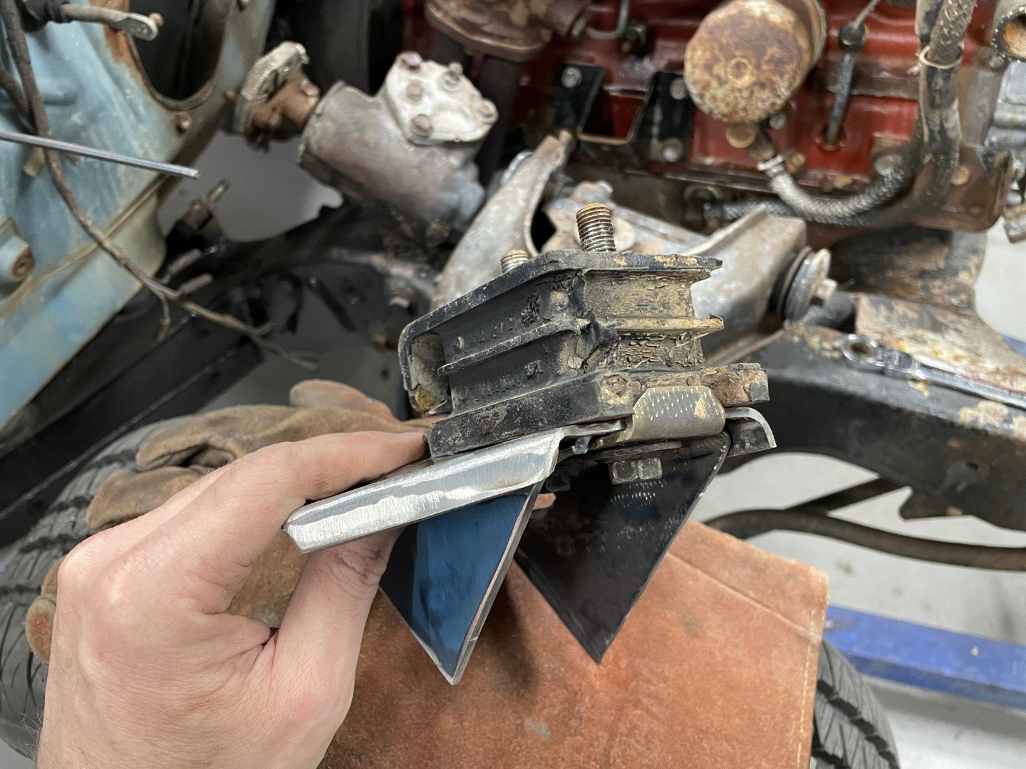
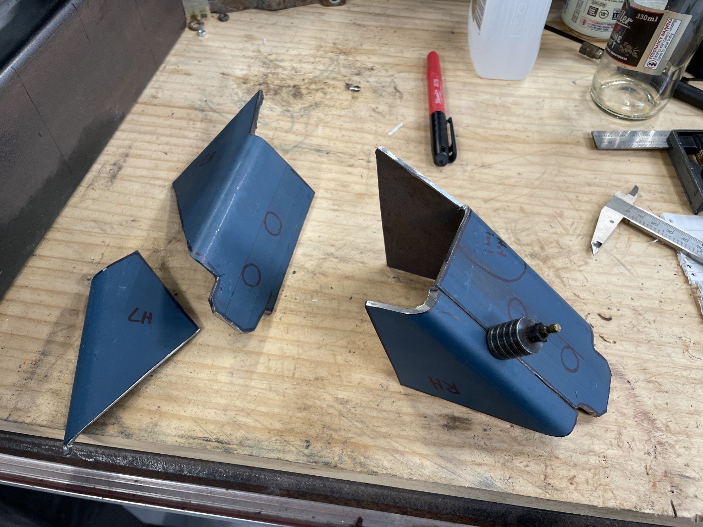
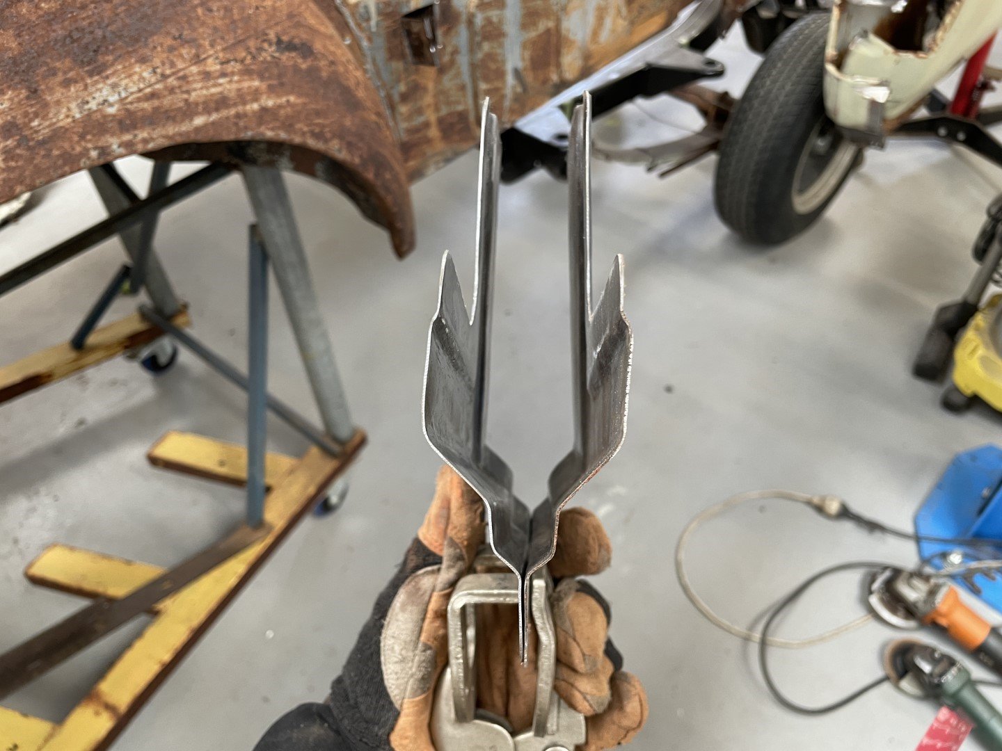
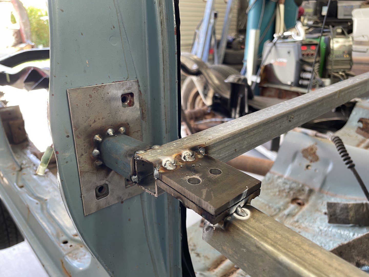
More hammering into shape had me a pair of things that looked like the thing they needed to look like;

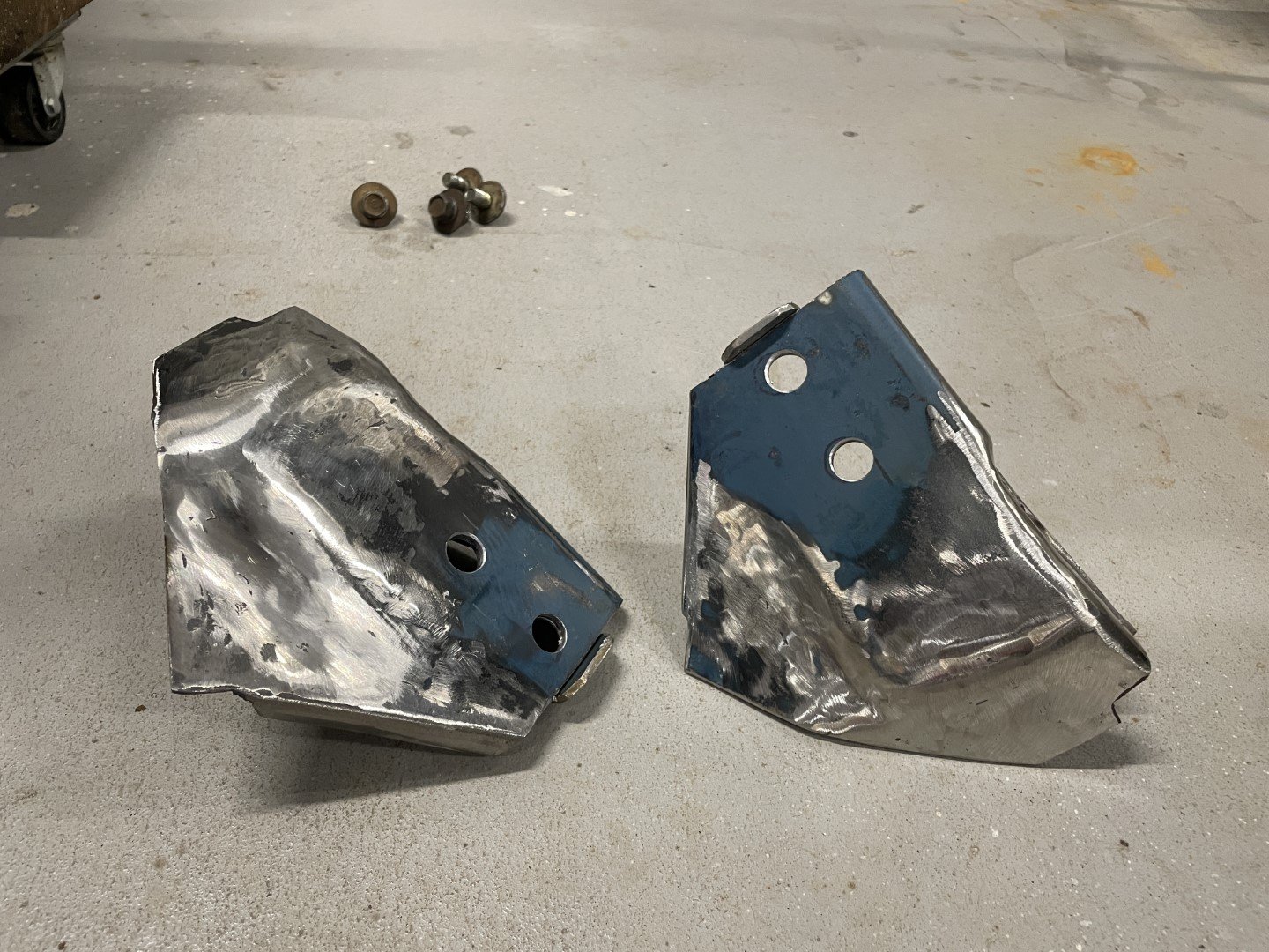
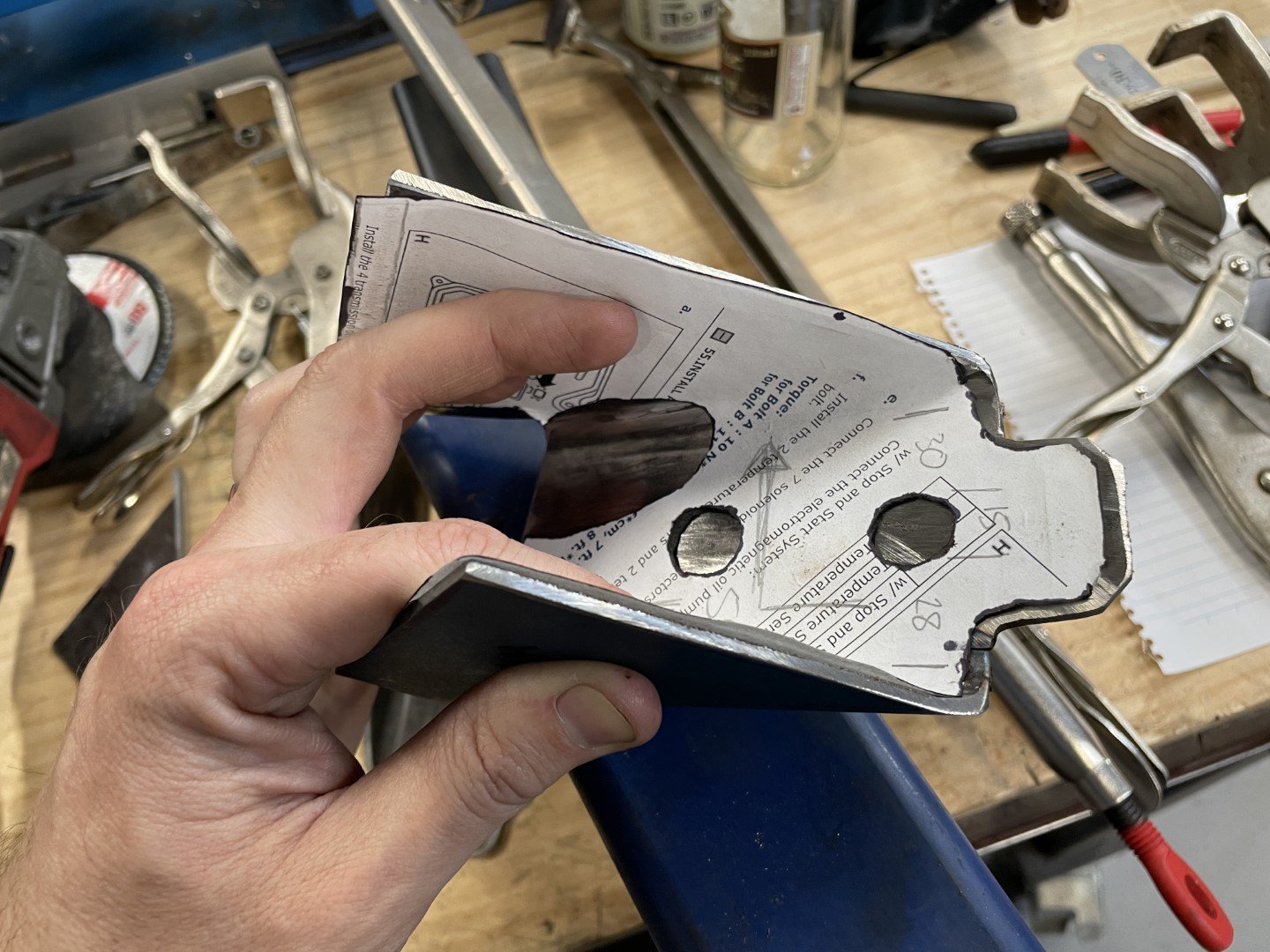
More hammering, tweaking and drilling had something that looked even closer to what they needed to look like;
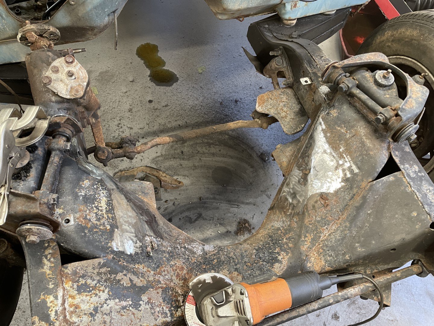
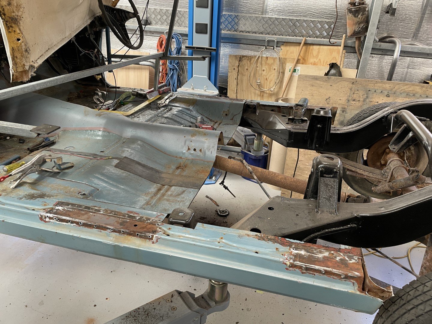
Got stuck in and pulled the boat anchor and transmission - then cut the R mounts off the chassis.
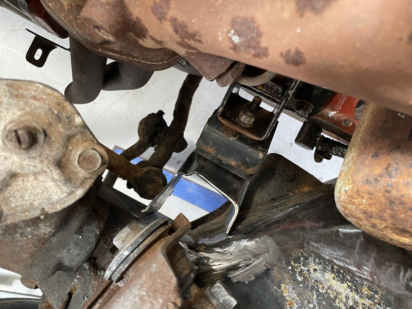
Swung the engine in and then fucked around for a few hours to try and get everything into the correct orientation.
Image to show mount + mounting components.
-
 7
7
-
-
Long weekend in WA gave me the opportunity to spend some time in the shed.
I considered working on mating the two halves together - unfortunately by brain couldn't see enough dopamine in doing that.
My brain suggested we do something cool, like work towards putting the M engine in between the front rails.
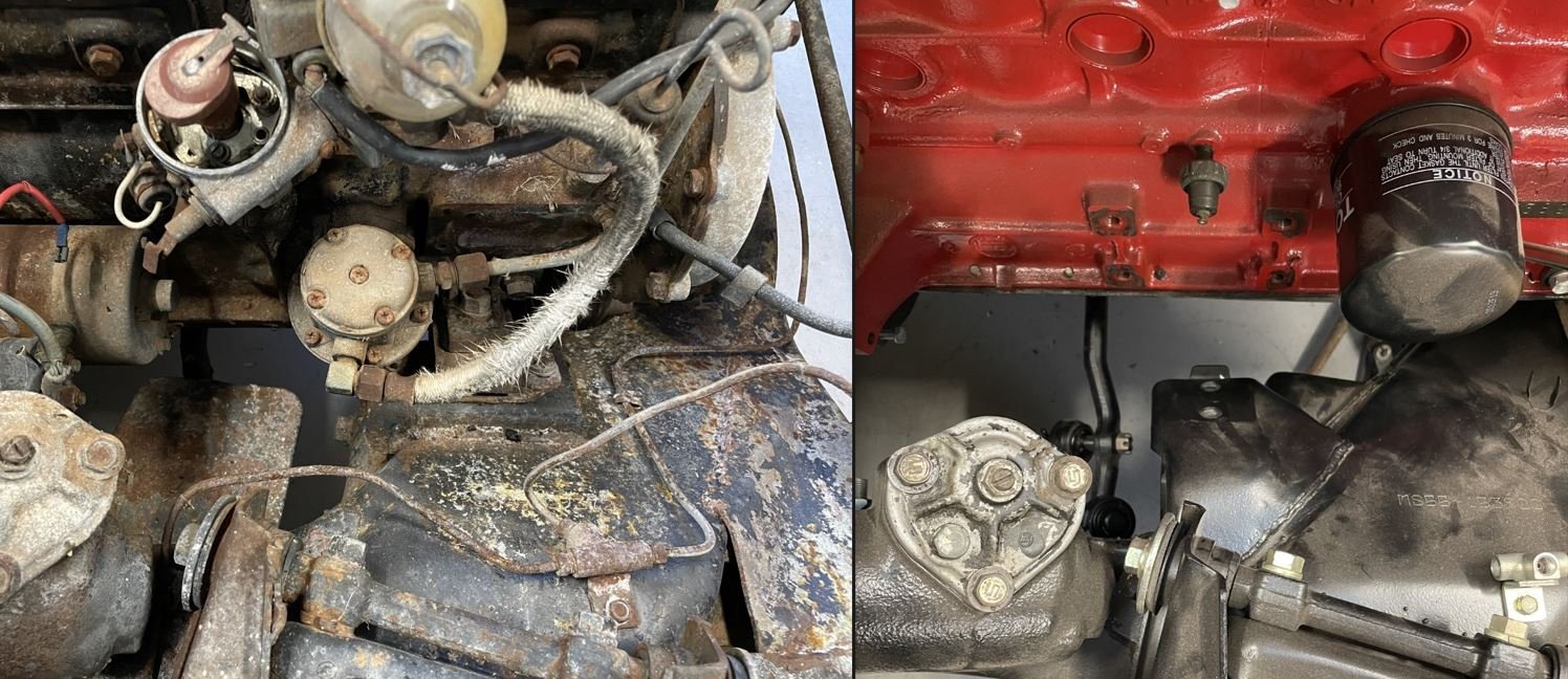
Issue the first - the damn R engine mounts and totally wrong for the M engine.
Luckily I have a partially disassembled MS55 to use as a comparison to see just how different they are.
To preface this, I had known about the discrepancy for some time - so I put the word out on the internets that I was chasing some mounts, with the hope that someone out there would have an old chassis that they could sacrifice for my greater good.
A few people reached out, but ultimately no one was able to help.
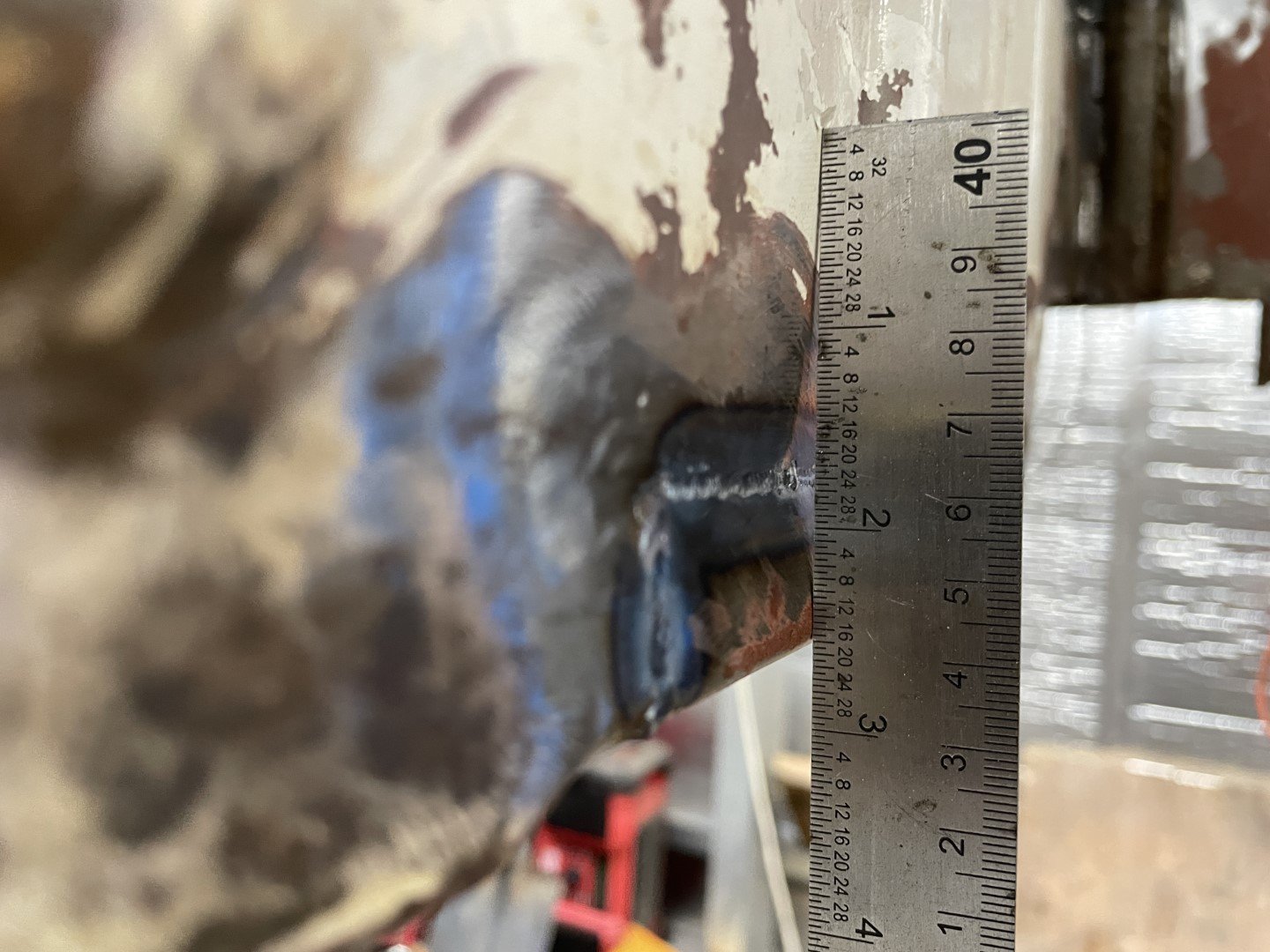
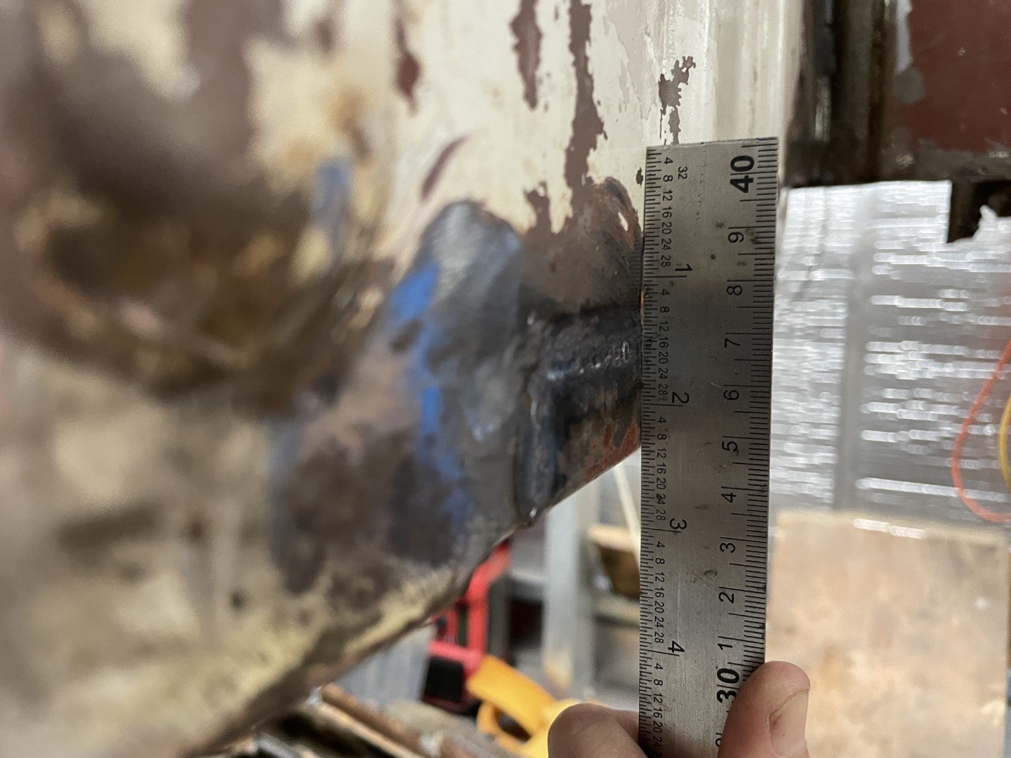
So after measuring up the material thickness of the OE mounts I dug through the steel pile to find some square tube that was close to the correct size.
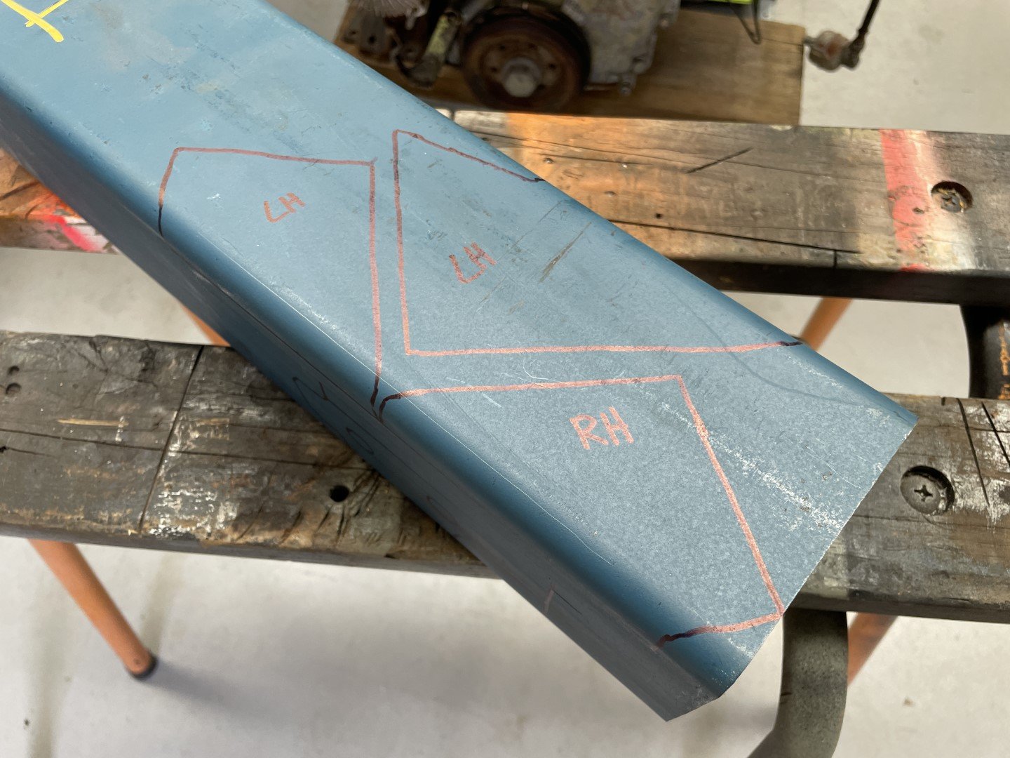
Then I made up some paper templates from the OE mounts so I could transfer the shapes onto the material.
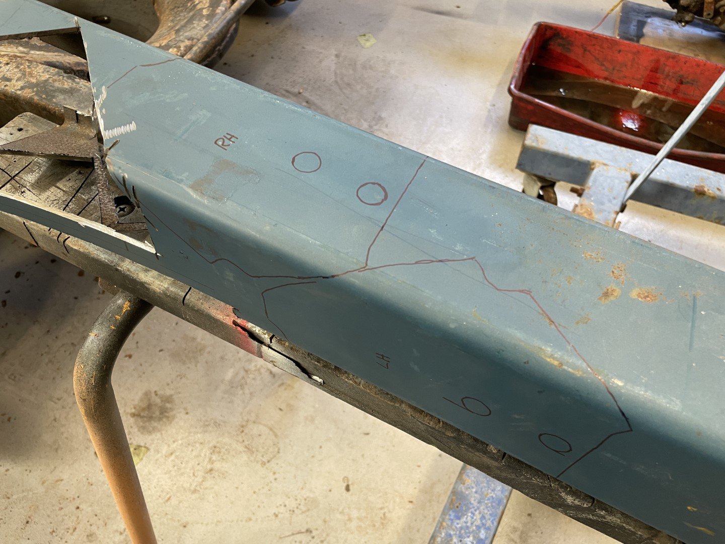
These mounts are made up of two separate components which aren't immediately obvious - paper templating the lower section was more difficult that I would have liked with the disadvantage that I was taking an inside measurement which I then used as an outside measurement - which kind of fucked things up a bit.
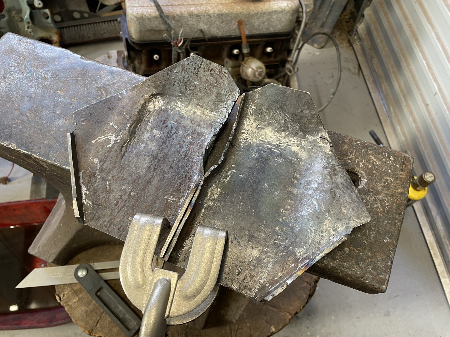
Anyway - I needed to do the lower pieces in two halves due to the material I had on hand not being exactly right;
Meh. Close enough.
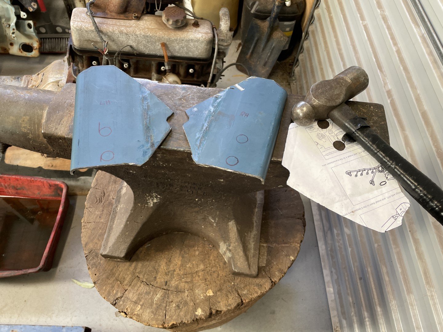
Then I templated the upper pieces, marked out and cut from the stock;
I then proceeded to FLATTERZIZE them on the anvil;
-
8
-
-
- Popular Post
- Popular Post
Heckin' long time since my last update.
Lazy?
Maybe....
Busy?
Yes.
In between the normal fatherly / husbandly duties, a family trip to the UK / Europe and work being generally mental - there has been very little time available to get at this thing. Thrown into the mix is home renovations which is undergoing planning / pre work - work. Not that I'm complaining - I acknowledge I'm in a very privileged position.
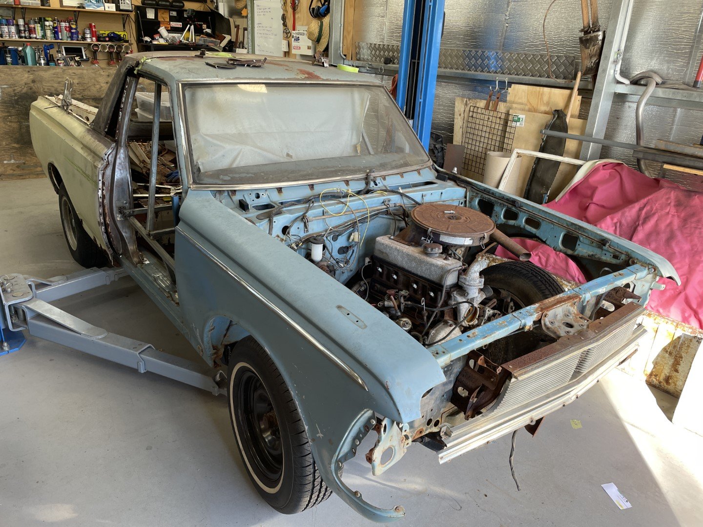
In amongst the craziness, I managed to obtain a 4M with a 4 speed that will find it's way into the Ute to replace the 5R that's currently in it. It's unfortunate that the mounting points on the chassis are different between R and M powered vehicles - even more unfortunate is the donor chassis I did have access to is no longer accessible to me
 It's not ideal - it just means it's going to consume some time replicating the M style chassis mounts.
Anyway - Father's day saw me presented with a ~2 hour window where I could get something done, so I headed out into the shed, shuffled all the shit around so I could drop the hoist down to get a good look at where I'd left everything.
The last time I had a play I stalled at the point of establishing the cabin position in relation to the tray - whilst the jig I made up to locate everything seemed like a good idea, it turned out to be totally good for fuck all.
It helped locate the 'B' pillar in relation to the 'A' pillar - but didn't account for levelness of the overall body - which was leading to headaches-a-plenty. The last thing I wanted was to situate everything where I THOUGHT it should go, only to find out later on it definitely wasn't where it SHOULD be.
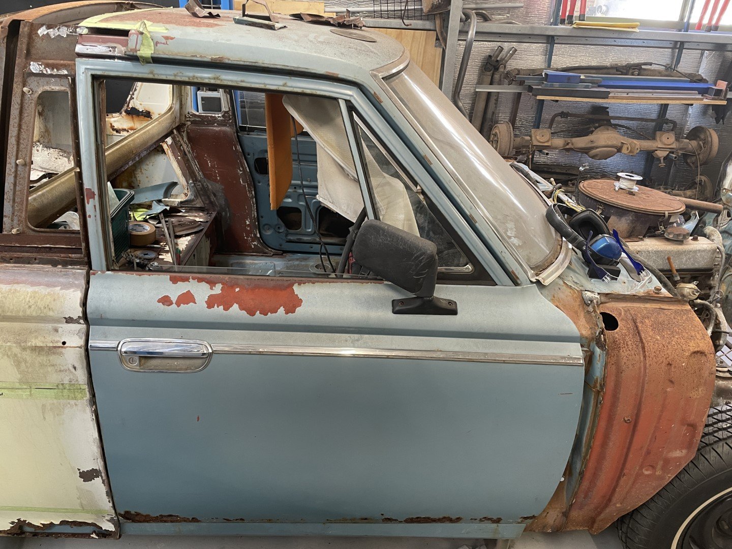
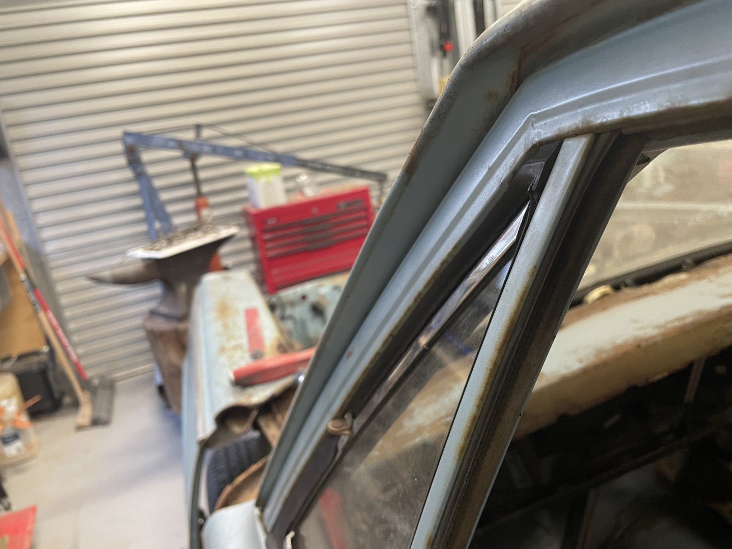
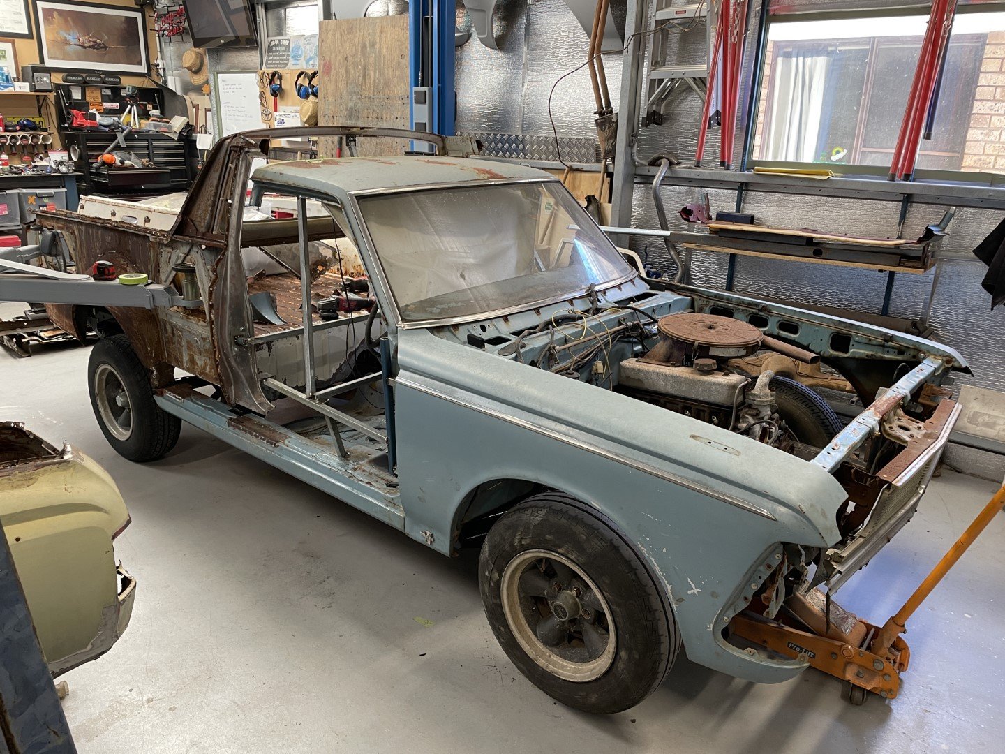
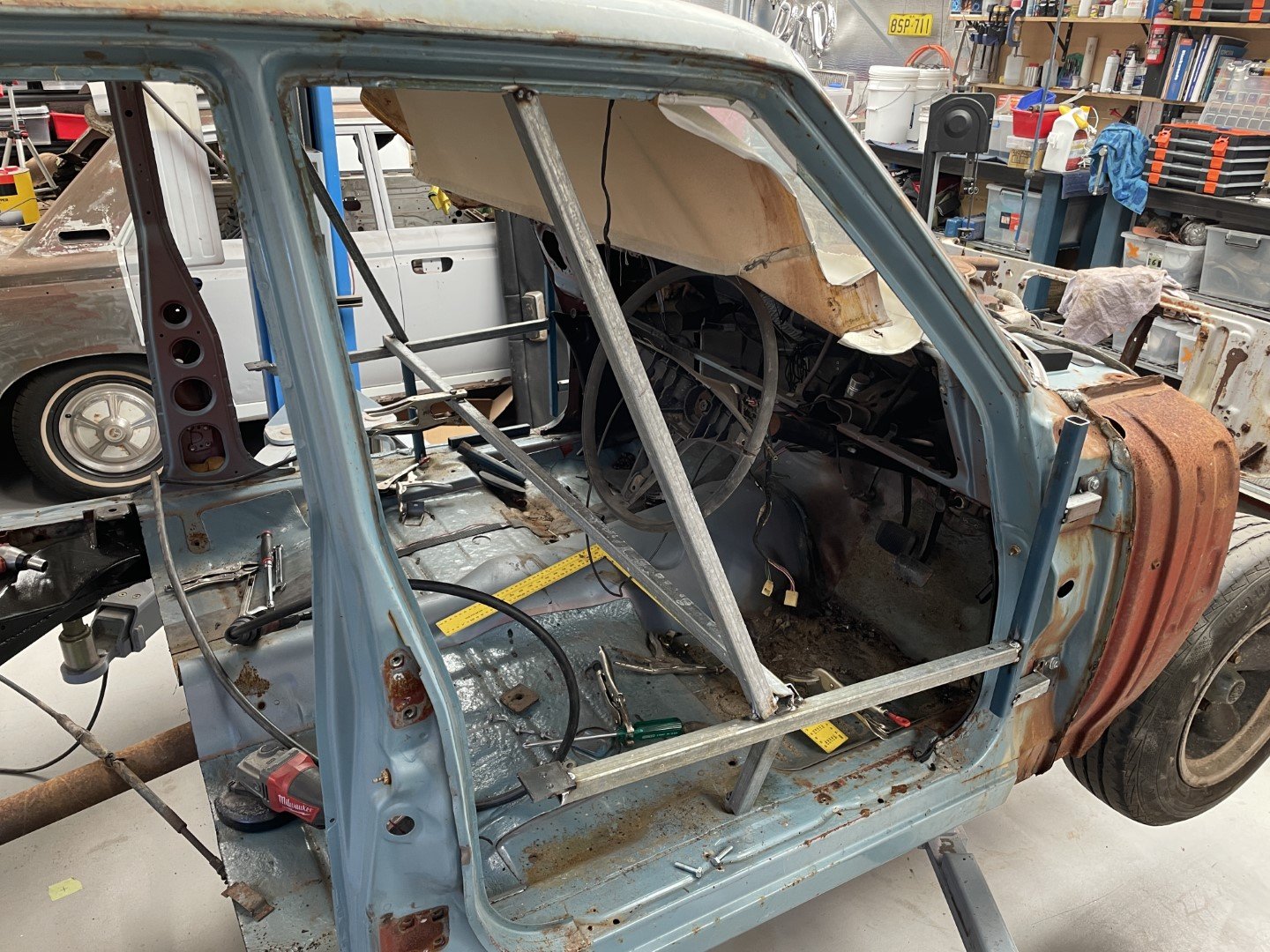
2 beers in I realized I had both OE doors from the sedan - so figured I could bolt them on (using the witness marks from the original hinge installation points) and align the gaps between the window frame / sill panel to get a better idea on where everything needed to go.
Initial fitment looked promising (apart from the general condition of the doors....)
There was a fair amount of adjustment that occurred after these photos were taken - mainly to adjust the align the window frame.
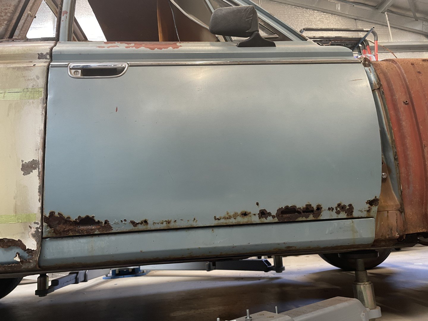
Managed to get the driver's side pretty well spot on (when compared against the MS55) but the passenger side was totally up to shit.
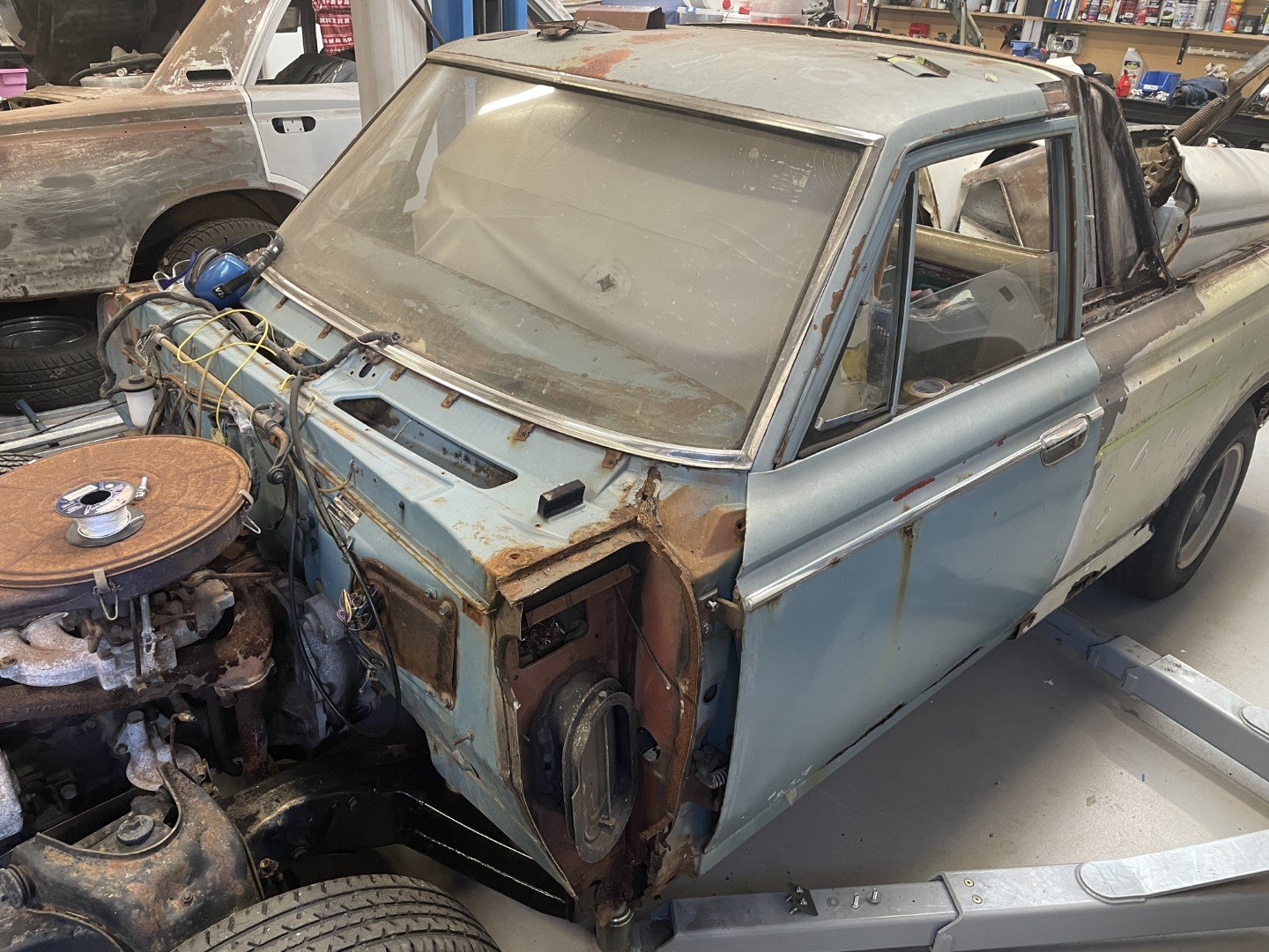
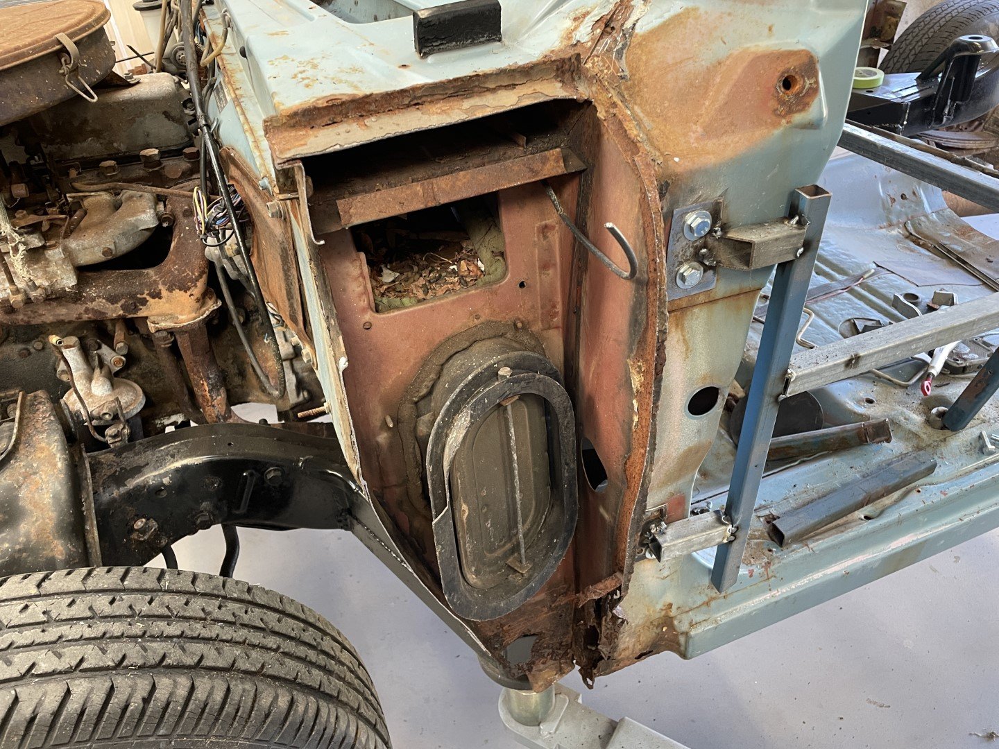
Then I remembered that passenger side had a history of collision damage (the plenum side cover was cut out by me as it had been replaced at some stage with a piece of sheet metal) which meant there was a good chance the OE door position was not going to be original.
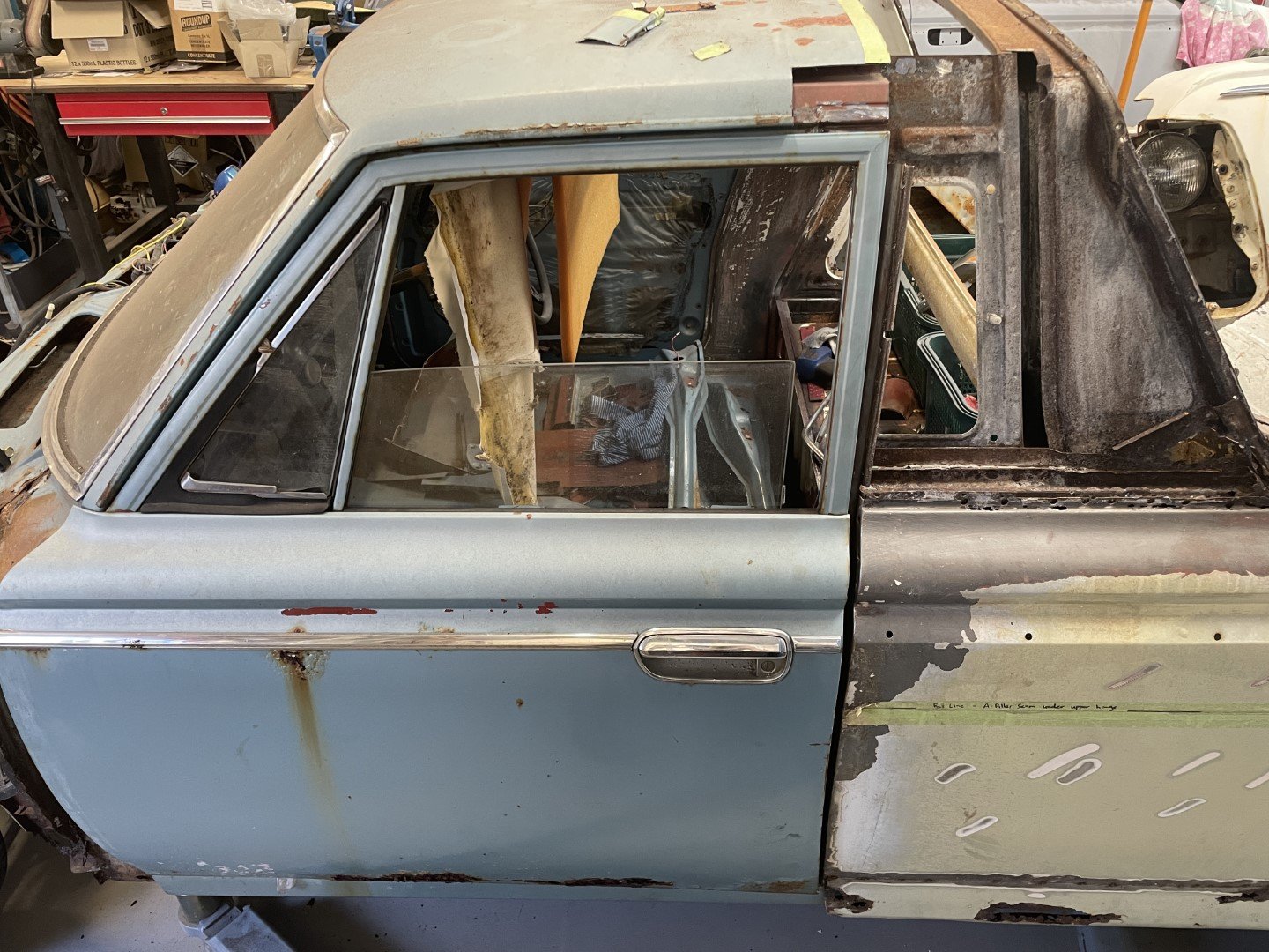
Case in point - the top section of the door was tucked right in at the top.
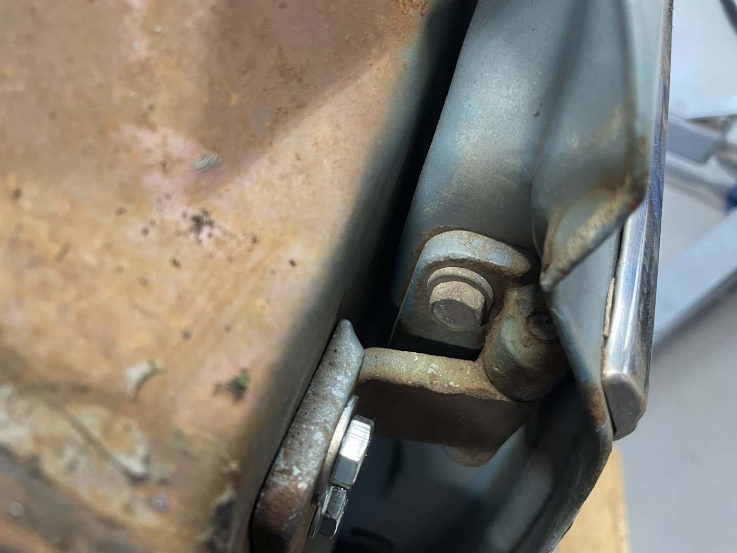
Witness marks on the upper hinge show adjustment suspected to cause the upper adjustment issue.
Spent some more time playing with the adjustment before the sounds of war started coming from the house which signaled the end of play.
So overall;
1. I'm happy to make SOME progress.
2. I think it looks super cool with more blue panels on it.
3. Although rusty, I'm digging the patina / rough look, so will carry that look on with the rest of the build.
-
21
-
- Popular Post
- Popular Post
Hectic days since last update - but still alive to tell the tale, so that's good.
Got stuck in and welded out the replacement steel - then spent a FUCKING ETERNITY grinding back the excess.
Yet another spot that no one will see (but I will know about) so whatever.
Inserted replacement steel into the lower sections that were rotted out too.
Decided to drag the TIG out and have a crack - the idea of ending up with a flat weld that would require minimal grinding made me all tingly downstairs. The welder I have is an Everlast 256 something something - TIG + STICK + PLASMA.
It came shipped with a 15A plug - which promptly melted once I tried dialing the plasma cutter up to 11 (60A) to cut some 16mm plate - which resulted in an upgrade to a 32A socket and dedicated circuit.
The issue with that is there is only one 32A socket in the shed - and it's never where I need it to be.
Found some heavy 3phase cable that I was saving for a rainy day (hoarding) and used it to extend the lead on the welder.
After putting my electrical ticket away, I got my welding ticket back out and jumped straight in.
No warm up.
No test piece.
Can you tell?
In all fairness - the small torch I used at the start had an issue (seems like it's drawing air in somewhere causing a shitty arc / oxidized the tungsten) so after changing out to the ultra large hand piece that came with the welder I got stuck in.
Turns out the only thing rustier than this ute is my TIG welding skills.
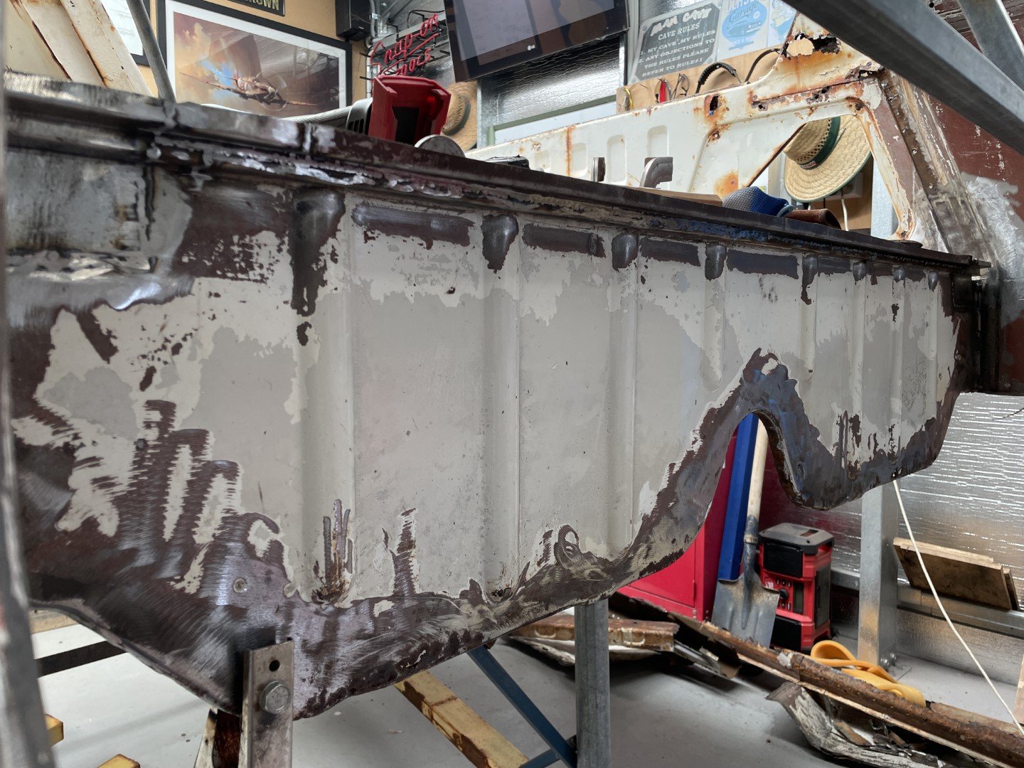
Anywhoo - one massively distorted (but flat-ish) weld later;
Planished the weld and gained some flatness back.
Called it good enough and moved on with my life (which meant packing everything away until the next available time slot)
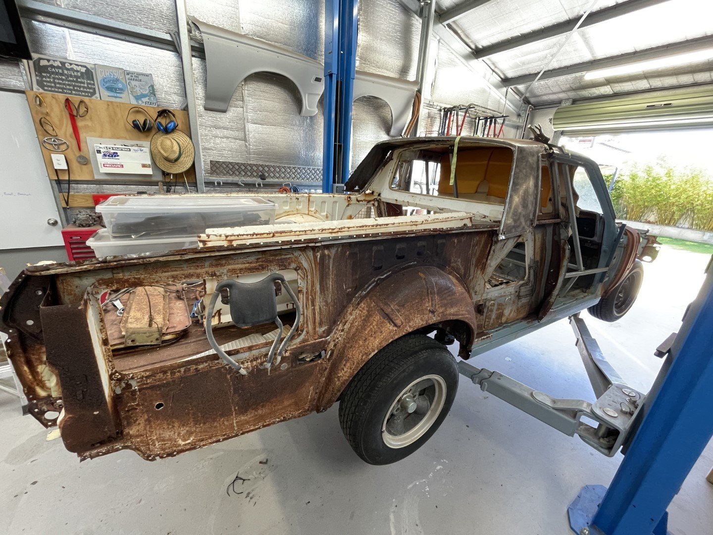
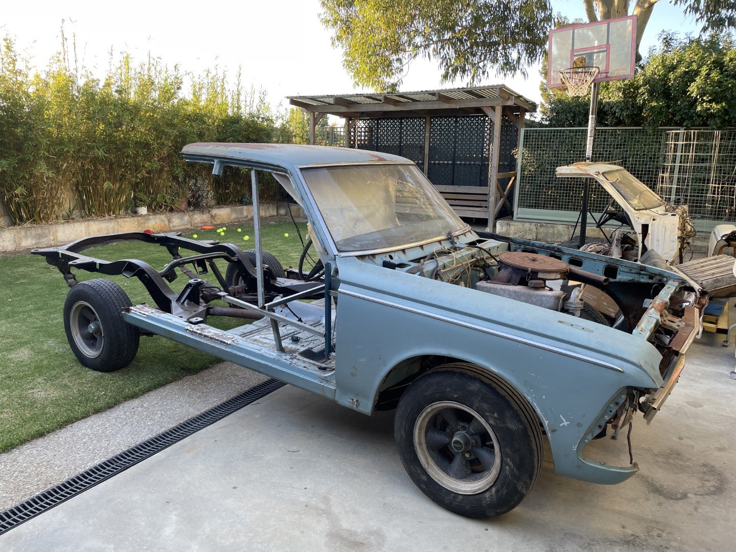
5 days later - operation 'clean up the backyard which looks like a fuckin junkyard' was put into play.
With the tray section on the trolley, the cab section on the hoist and the chassis sitting outside ruining the aesthetics of the backyard - there was a whole heap of car spread out everywhere.
So I slipped it all back together.
It's amazing how much room you get back when you put a car back together.
Added hanging panels for maximum AWW FUCK YEAHS.
The wife has scheduled me some shed time on the weekend - that will hopefully give me the opportunity to do the final line up before welding the two pieces together.
-
25
-
 3
3
-
Absolutely sensational build - all while keeping the car on the road!!!
Additionally, I commend you on your workshop cleanliness - it's inspiring to say the least!
-
1
-
-
- Popular Post
- Popular Post
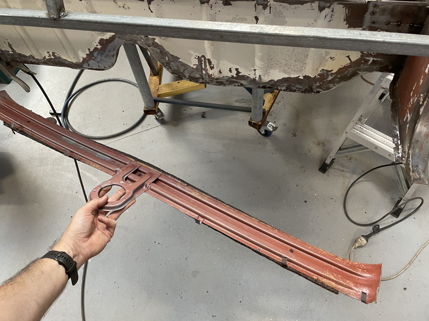
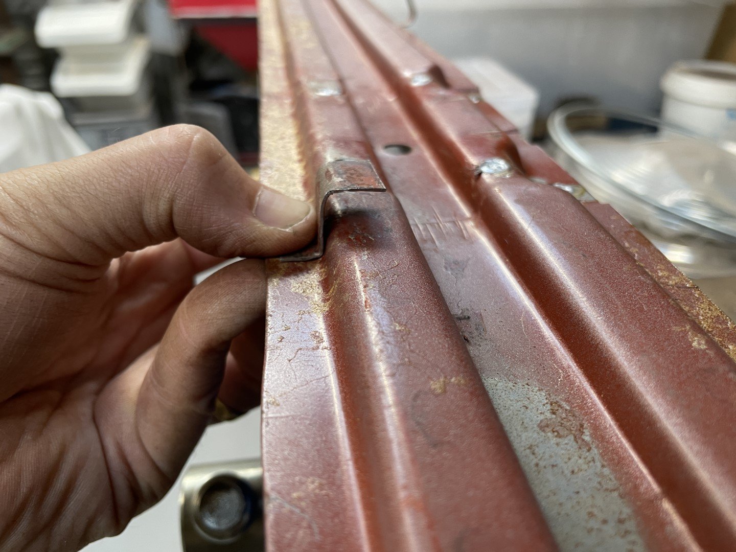
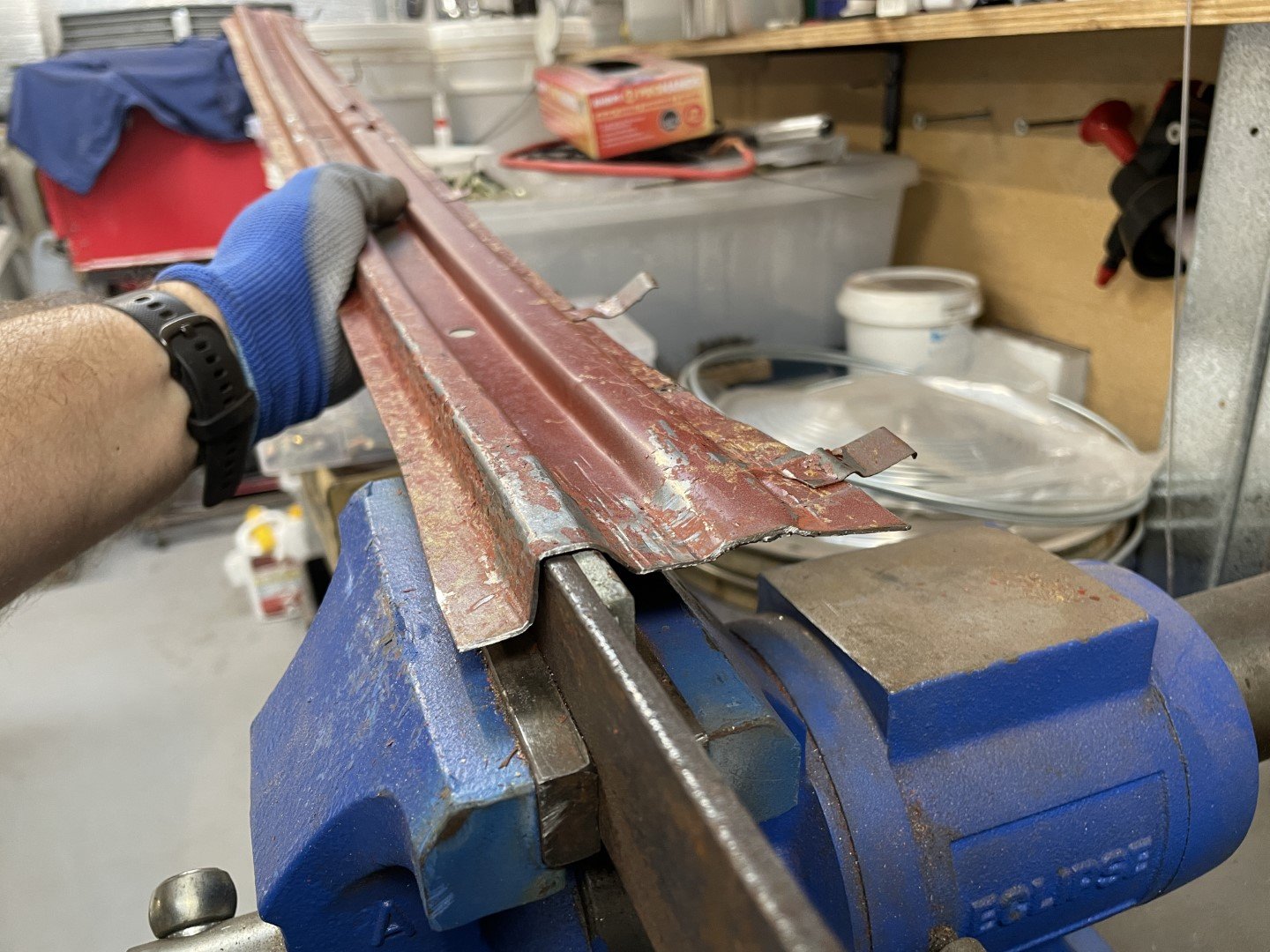
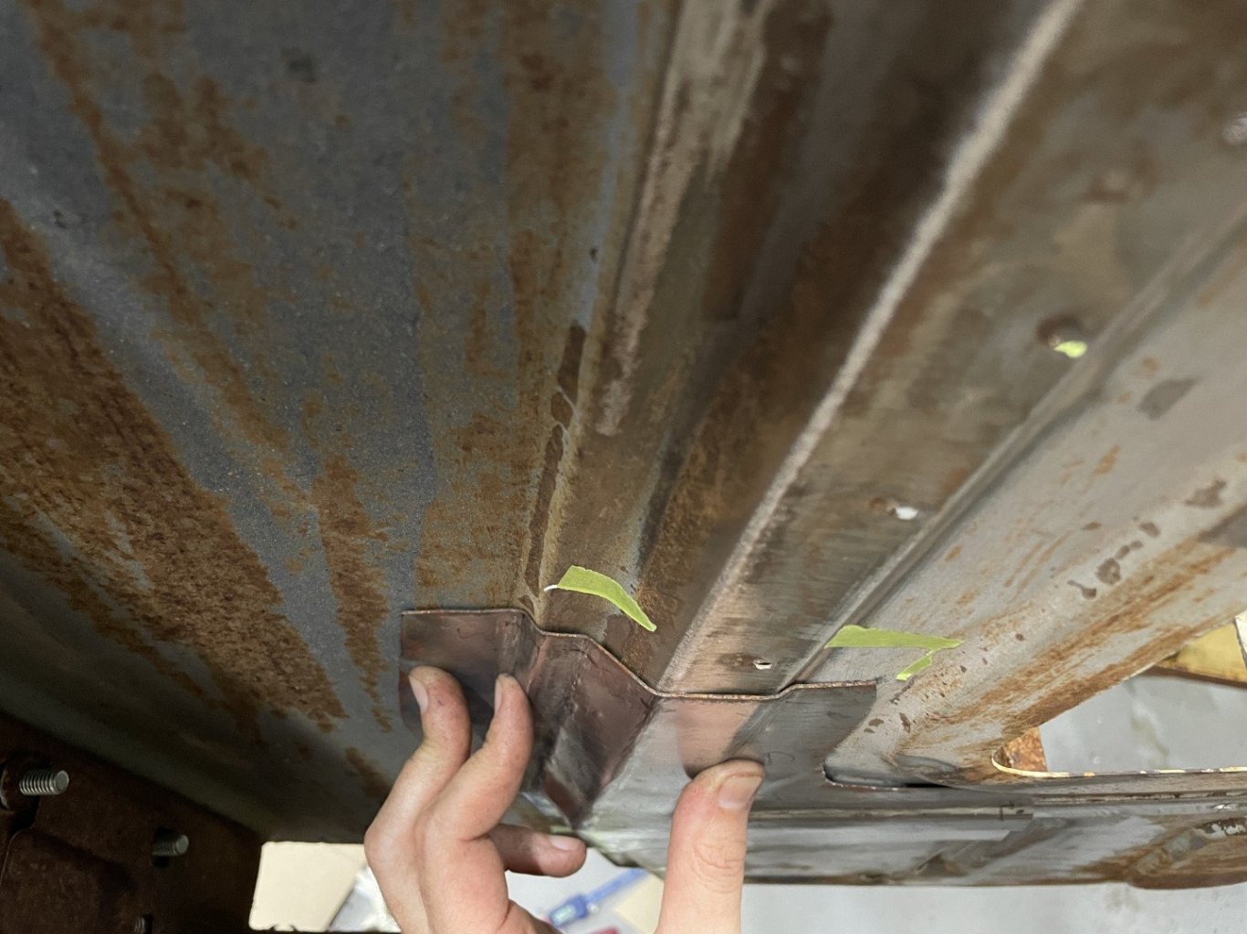
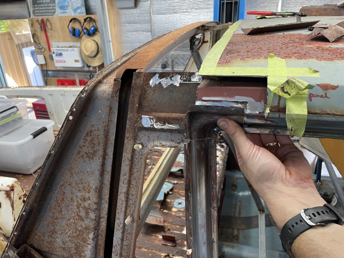
Not having a sheet metal folder (anymore.... I did have one, but sold it for lack of use / annoyance it presented by always being in the way) or any sheets of suitable steel that I could use to bend a continual replacement piece - I had to find another immediate solution. Looking at the pile of scrap metal cut from the sedan revealed the middle roof support (which had the sedan interior light bracket attached)
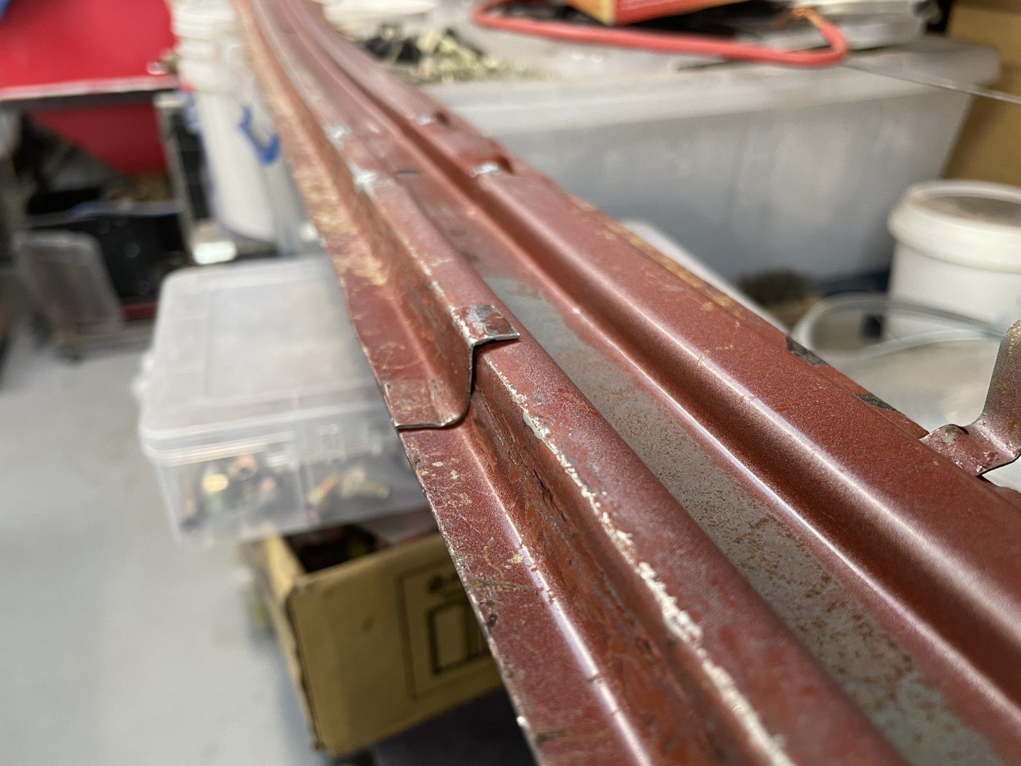
Seemed to be close to the right length - however the step wasn't quite right. Carried on and drilled the interior light bracket off. Photo below shows the variation in step heights.
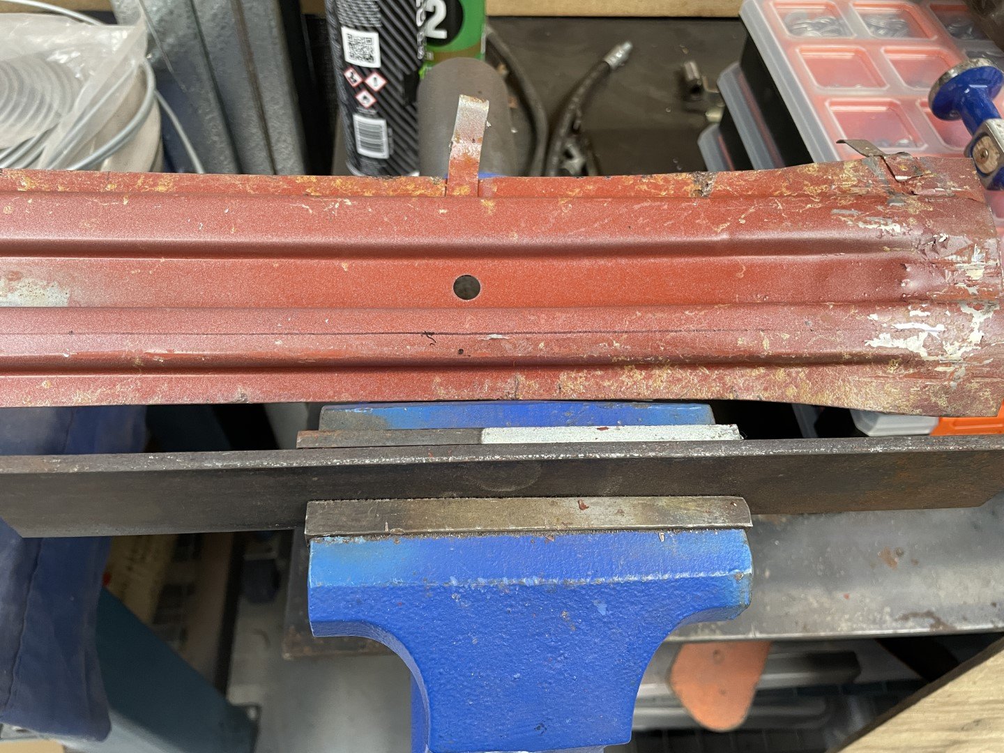
Figured I could just beat the panel into submission to achieve the required profile. After marking a line for where the bend needed to be, I set a couple of pieces of flat bar in the vice and had at it.
After much hammering the desired profile was achieved.
After cutting the required piece away, I spent more time hammering the panel to remove the epic bow it had taken on (from having metal stretched in one area, but not the other) before moving on to matching it up with the ute body.
The panel still had quite a bow to it - but knowing that welding it in was going to require follow up hammer and dolly work I wasn't too stressed.
The Mrs suggested that a 5pm knock off and a walk around the block with the kids would be a good idea, so I quickly tacked the panel onto the body in a 'close enough = good enough' fashion before stumps.
A few gaps were filled (including a 50mm gap at the other end as a result of the panel not being quite long enough) before I switched off the welder and headed out to get some fresh air.
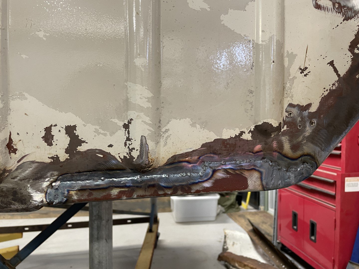
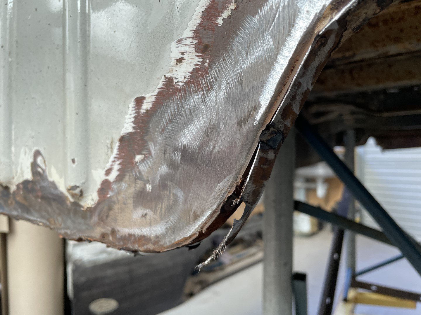
Also of note - I ground back the welds on the back side of the panel I welded in at the start of the day (although no one will see the welds when the rear 1/4's are back on) purely to allow me to planish the welds.
Planishing the welds stretched the material that had shrunk during the welding process and flattened the panel substantially - a quick pass over with a flap wheel saw the welds almost disappear (as per above photo). Happy with that!
-
24
-
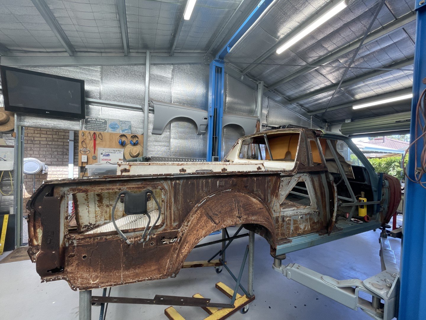
Had another successful weekend in the shed working on the ute. I'm pushing hard to get the two car halves stitched together as soon as possible so that the car can be condensed into one - the space that the chassis, front hand, rear half and OE RS56 front half consumes is getting out of hand.
My shed is starting to look like a hoarders den - with small passages and alleyways providing access to the various troves of parts and tools hidden within the workshop.
As a family, the upcoming year is going to be massive - a couple of overseas trips within the next 8 months combined with plans to renovate the house is giving sufficient motivation to free up some space in the only domain I have total control.
Fortunately, my wife is an absolute champion - and after a quick chat over the morning coffee she gave me her blessing to abandon her and the kids for most of the weekend and the promise of allocated time on the upcoming Anzac day public holiday.
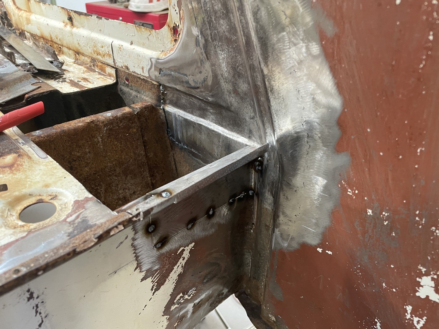
So I got into the shed and tried my best to stay on target - which was resolving the rusty spots that would later be difficult to work on once the two halves were merged.
The inner structure panels were fully welded in and the weld penetration to the inside ground back. Not aiming for a file finish - but close would be nice!
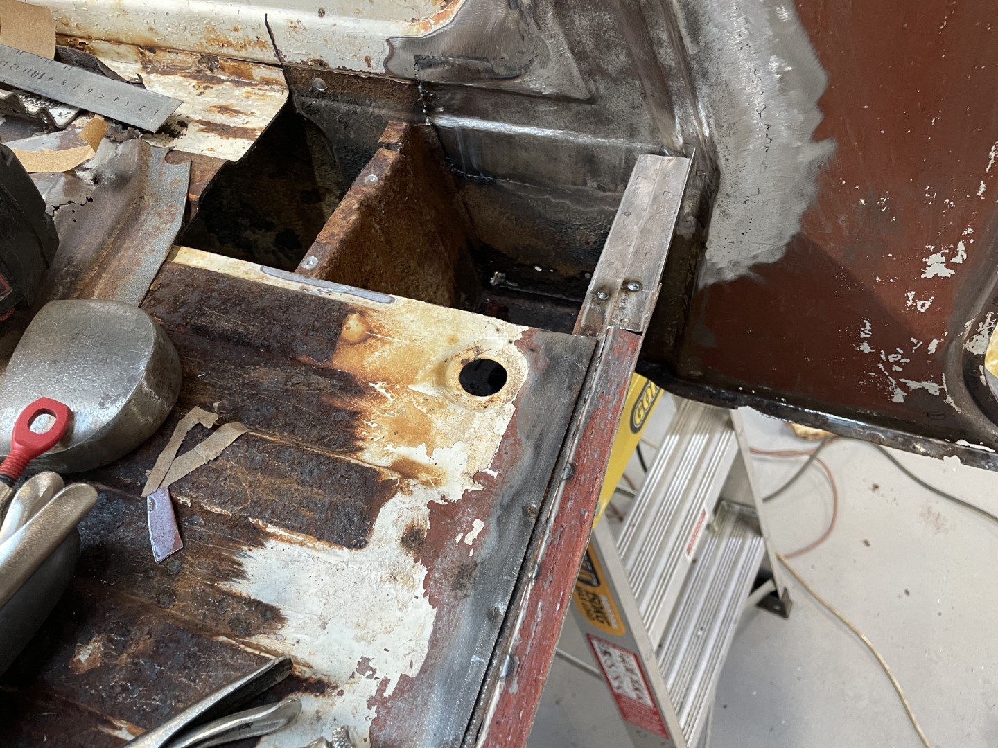
Once that was done, I moved onto the lower section of the rear firewall. I slipped the upper firewall section back in to help establish where the missing metal was. Folded up a small template to show where steel should be.
Made a paper template up to pick up the key fold lines and general shape based on the best guesswork I had to offer.
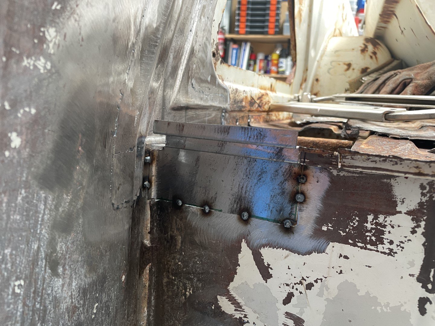
After tweaking the template, I marked out two pieces of steel to make a patch for each side.
Replacement panels then folded, trimmed and spotted into place.
Once I got those situated, I moved onto the next big piece which was continuing the upper lip to which the upper rear firewall section spot welds to.
-
7
-
-
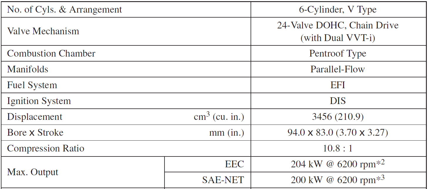
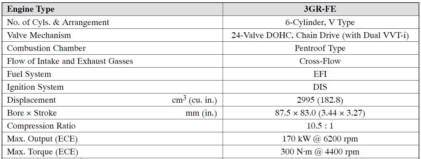
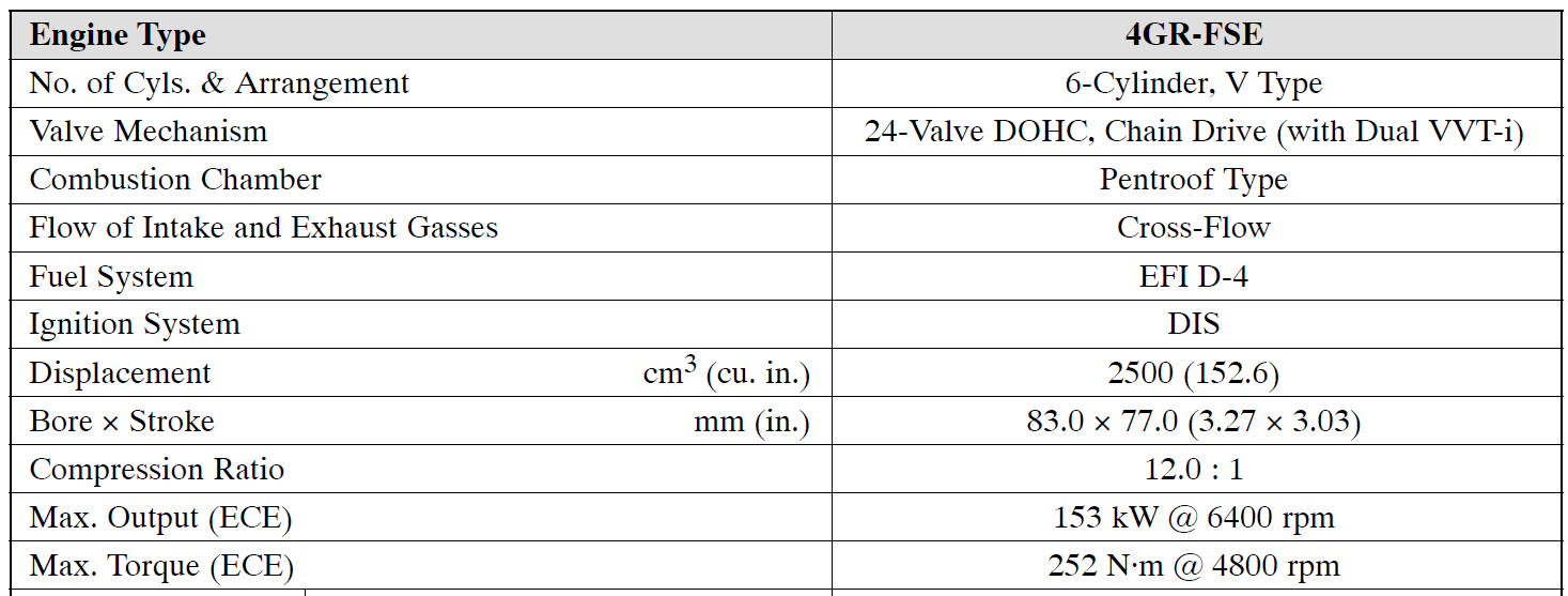
No doubt you've already done the comparison somewhere - but thought it was interesting to look at the 2GR, 3GR and 4GR engine specs side by side (or more accurately top on top)
2GR
-
1
-
1
-
-
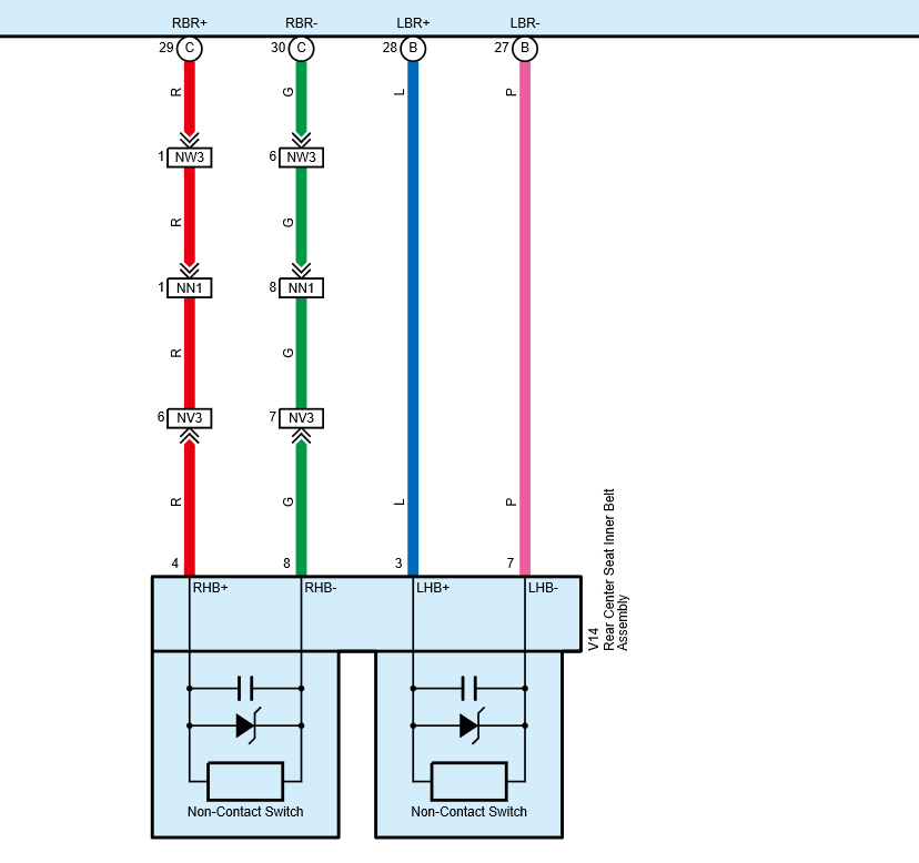
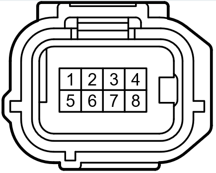
This here will be the reason the airbag warning illuminates when you disconnect the second row seat belt buckles - they are connected to the SRS ECU via the 8pin connector.
Just in case anyone was wondering, the connector housing can be purchased individually (part number 90980-12520)
Terminals for the above connector (with 160mm of wire) can also be purchased from your friendly Toyota dealer 82998-74030.
Obviously, the information above is just to help repair a broken connector / wire - you know, in the event it becomes damaged or something.
Not sure what is actually in the inner seat belts that tells the Airbag ECU is all ok either - but If I had a Hiace I would be most interested to investigate!
-
2
-
1
-
-
- Popular Post
- Popular Post
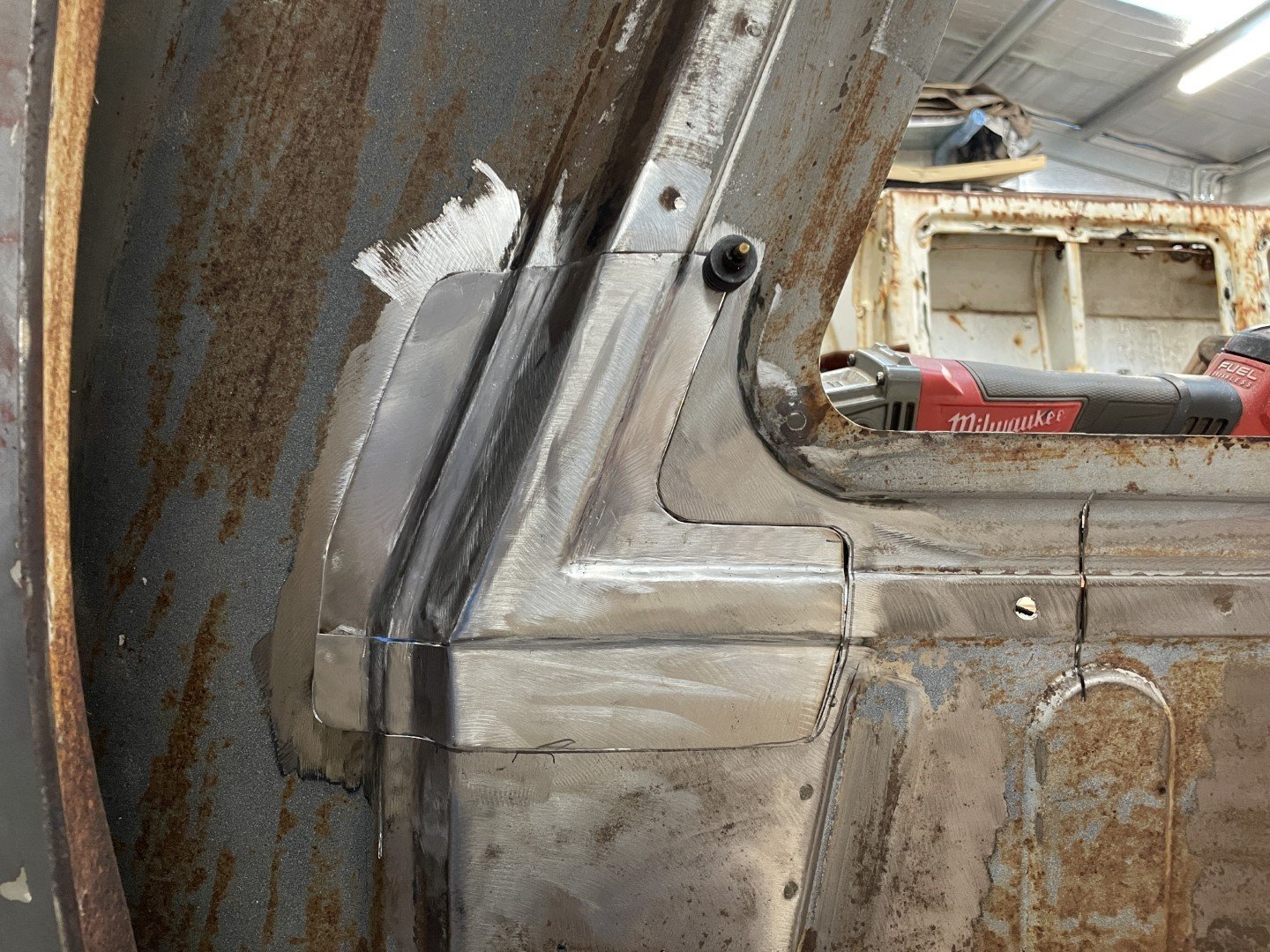
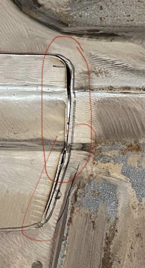
After getting that side spotted in, I moved back to the LH side to see how well I could get the first patch integrated.
After I marked it out, I used the step drill to knock out the internal corners before attacking it with the 5" grinder.
Old steel sat on new panel.
Dropped the patch in after a little work tidying up the hole I'd made.
Super happy with how the swage lines matched the original steel profile.
In my haste to make it fit as the day drew to a close, I absolutely botched with fit on the back side - leaving a grand canyon to fill in with the welder.
Figure it was a good enough time to pull up stumps for the day.
-
26
-
2
-
- Popular Post
- Popular Post
I was happy with how it all lined up - swage lines seemed to be in all the right spots even after worrying myself that making the patch over the top of the existing panel would lead to discrepancies.
Got the welder out and proceeded to blow holes through the panel (hadn't bothered to check the welder settings)
Some fine tuning with the hammer and dolly got the piece sitting where I wanted it.
-
11
-
- Popular Post
- Popular Post
Weeks have passed - managed to sneak out into the shed and get some more work done on the ute.
Figured the best way to re-introduce myself to the rust repairs was to create a patch for the other side.
Then I realised that I couldn't remember the exact steps I took to make the corner patch for the LH side.
Found the paper template, cut out another piece of roof steel and marked it out using a center punch as per the LH side.
No images taken of the steps taken to make the patch - but the result was something close to what was needed.
Clamped it against the piece I made for the LH side after trimming it to the same size as the RH side to gauge how close I'd got it.
Was pretty happy with that, so committed to getting it stuck in.
Took a lot longer than I'd hoped for, but was happy with the fit.
-
15
-
10 hours ago, dabuzz said:
You are fking crazy
I love it
IMO You really should get both halves blasted and epoxied before going too far (like you haven't already
 ), makes life so much easier in the long run
Ha ha ha ha
Thanks!
Agreed, blasting + epoxy on both parts would be best.
Unfortunately it’s not money I can justify spending when taking all other life costs at the moment.
I’ll just have to settle for a wire wheel and rust converter / sealer for now.
All junctions will be treated behind the seams to the best of my ability - which will be 100x better than the effort spent at the plant it was built (and it still lasted 50+ years!!!) -
8 hours ago, Nominal said:
Good to see someone else tackling a massive rust bucket.
Your patch looks good, but I wanted to point out that if you make it to fit over the existing panel, it won't be quite right when you cut the rusty bit out due to the metal thickness - your swage will be wider etc. For a hidden piece like this it won't matter much, just adjust the ends to match at the cut.
Thanks for the feedback mate - duly noted. Figured my method would be somewhat agricultural and that there would be some variation once I cut the rusty shit out.
I’m fortunate that no one will see this once it’s got a 1/4 panel over one side and bed liner on the other.-
1
-
-
- Popular Post
- Popular Post
After multiple stoppages over the course of the day (required to stop kids from killing each other / wife losing her mind) I moved onto ACTUALLY trying to fix something.
With good access to the inner structure now that the 1/4 panels weren't on the vehicle, I set about working out how to make a patch panel.
Now, I've watched plenty of YouTube videos (Fitzee's Fabrications for example) and figured I would approach it in the manner Fitzee would - using multiple pieces welded together to make a complicated shape.
After gathering up metal scraps, and establishing the best direction to attack the better of the two corners (P/S) - I came to the realization that I was in no mood for a shit load of cutting, welding and grinding.
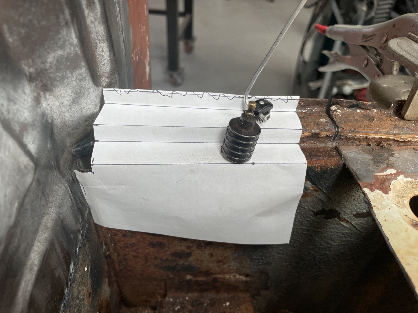
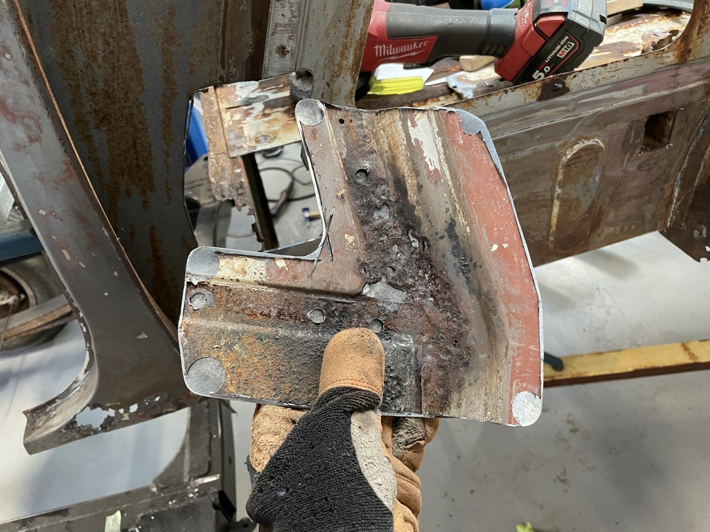
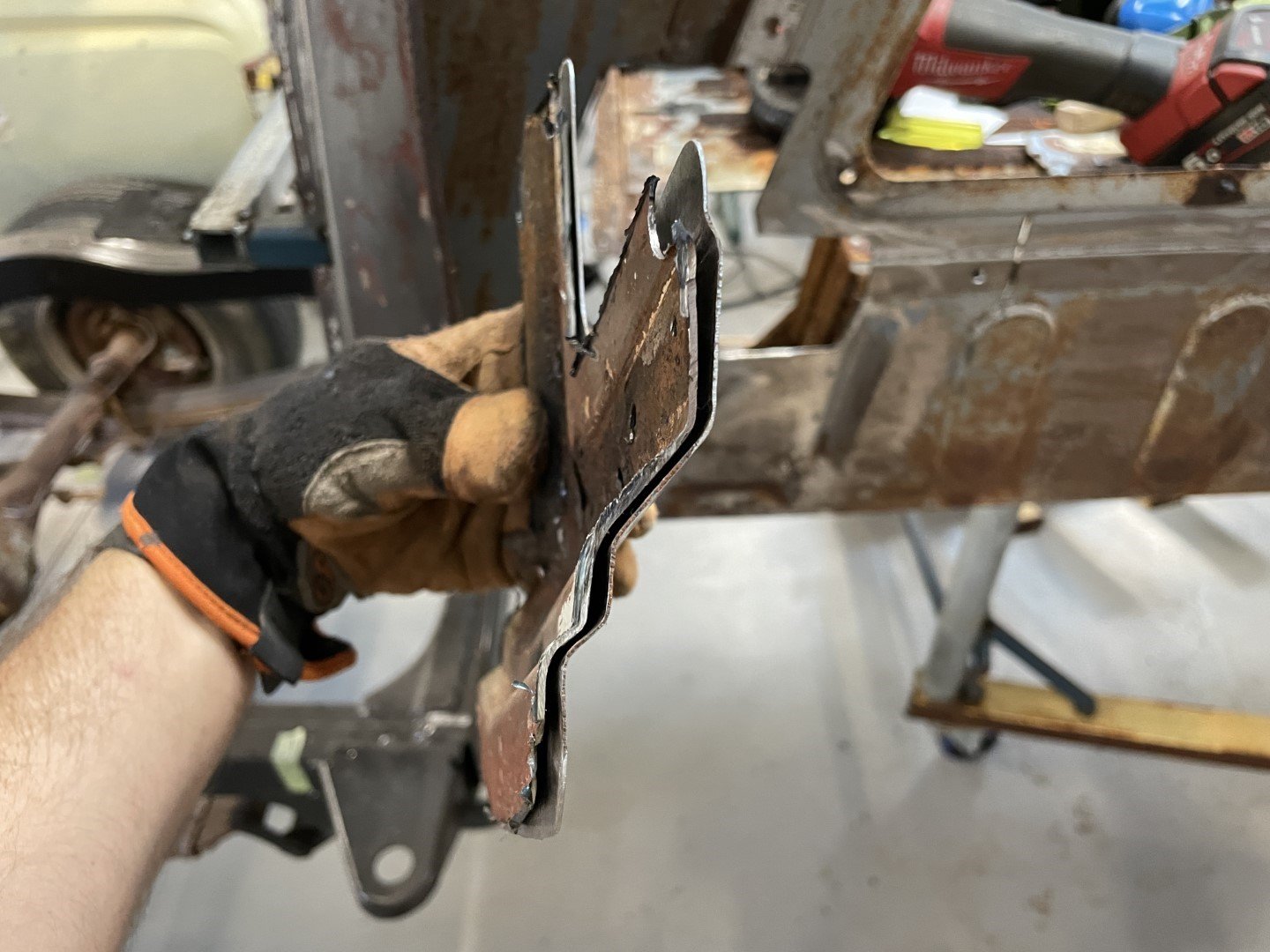
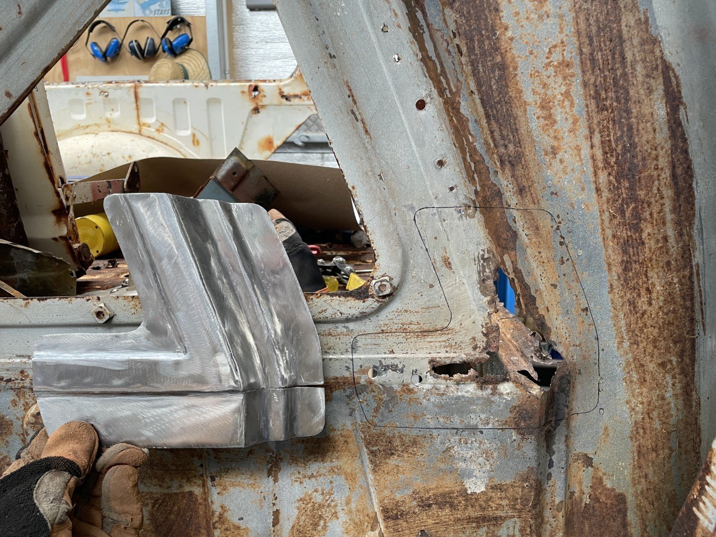
So I thought I would have a go at making a paper template that would pick up all of the important profiles and shapes that I could then go on to bash into a piece of metal.
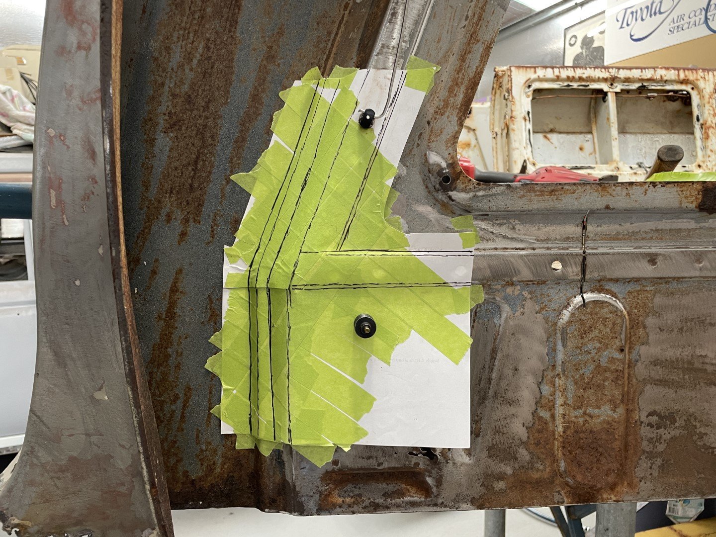
I put a piece of paper over the area I needed to copy, pressed and contoured it then put some tape over the top to give it some form.
The masking tape did OK, but the template would have been much better if I'd had some of the reinforced plastic tape that the professionals use.
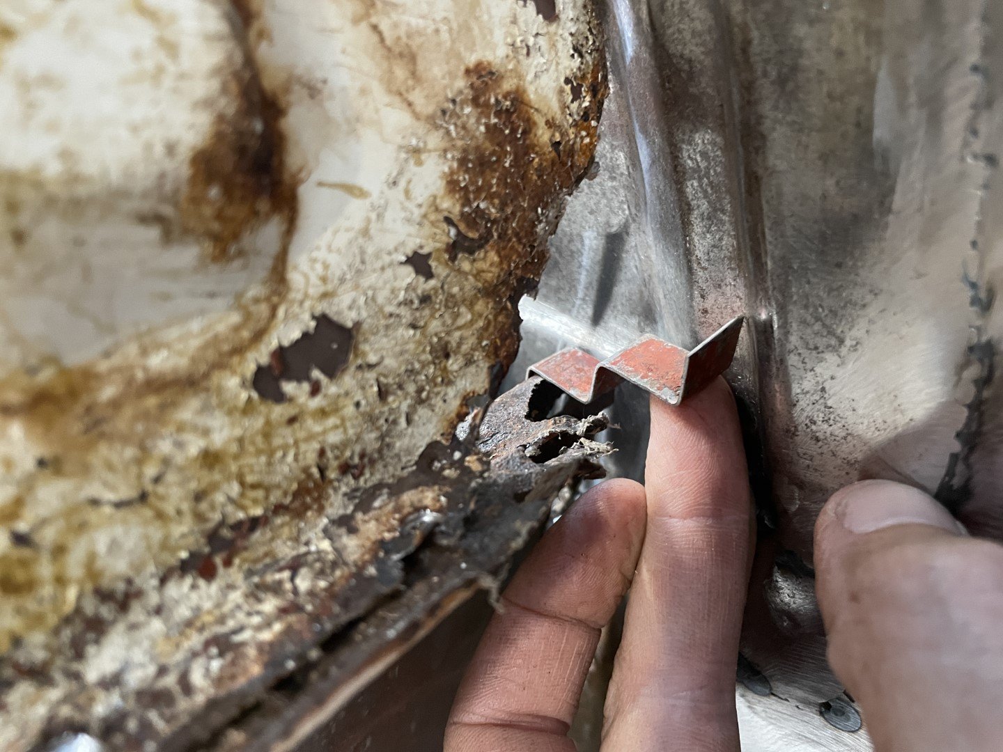
Close enough to good enough, I checked it against the other (more fucked) side to make sure the upper rust holes were covered.
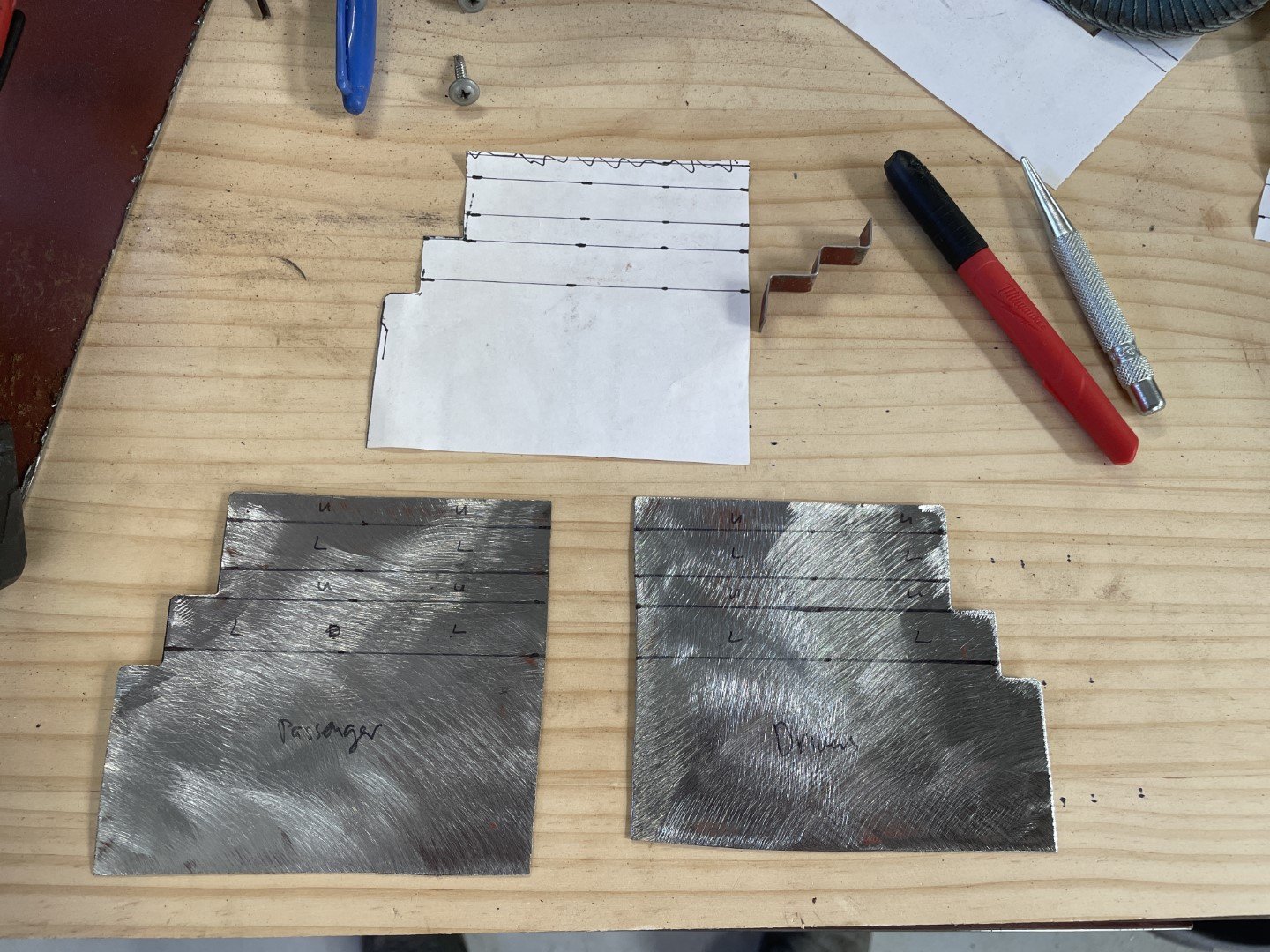
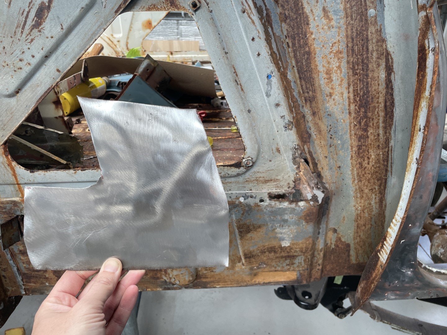
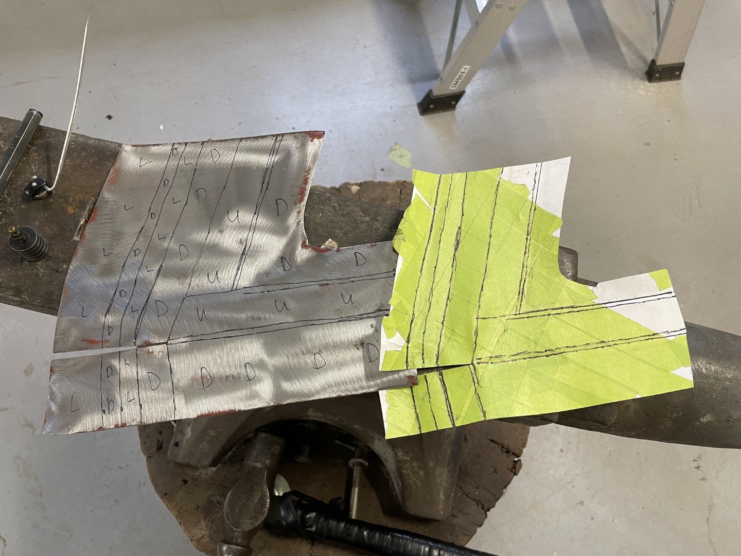
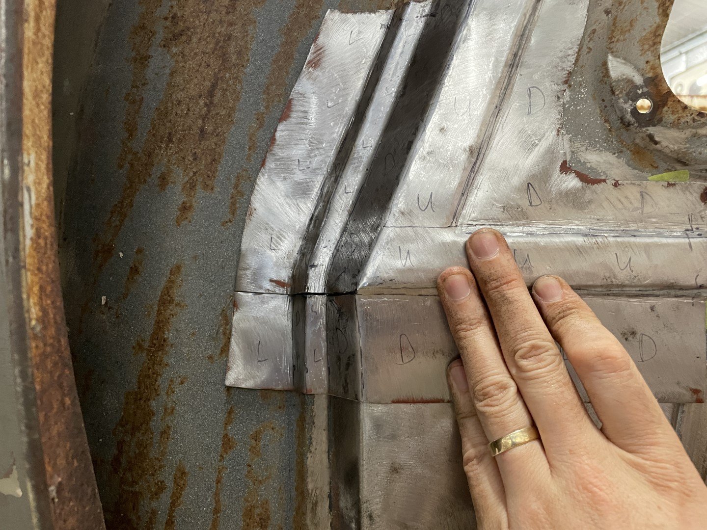
I cut it down, then found some NOS sheet steel (piece recovered from the strip cut out of the sedan's roof panel) and then transferred the contour lines with a center punch.
Intricate code on the sheet identified which profiles were UP, which ones were DOWN and which ones were LEVEL (which made total sense in my head at the time)
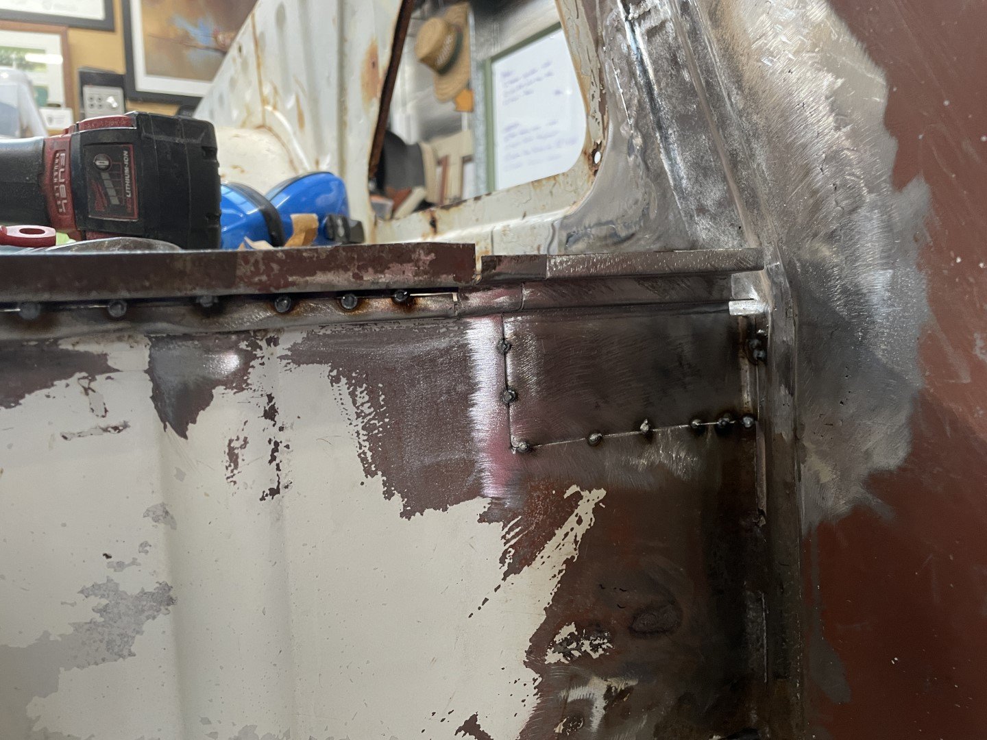
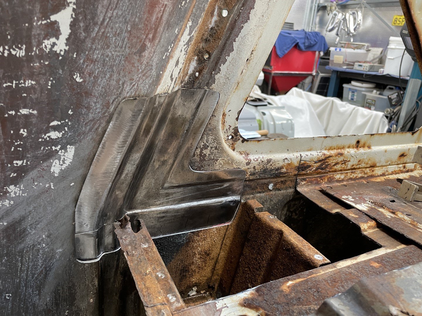
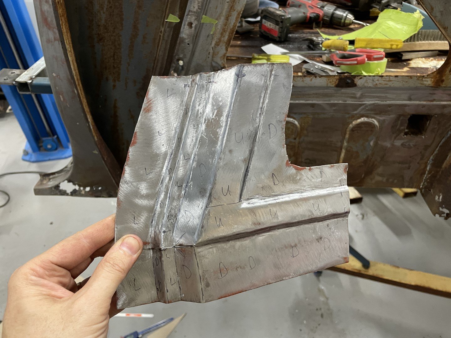
Moved the anvil near the car and then proceeded to tap tap tap, bend and tweak until I ended up with something close.
In all honesty - it didn't seem like a particularly difficult piece to make. Got lost in the back and forth between the body and the anvil until I had something that was pretty close.
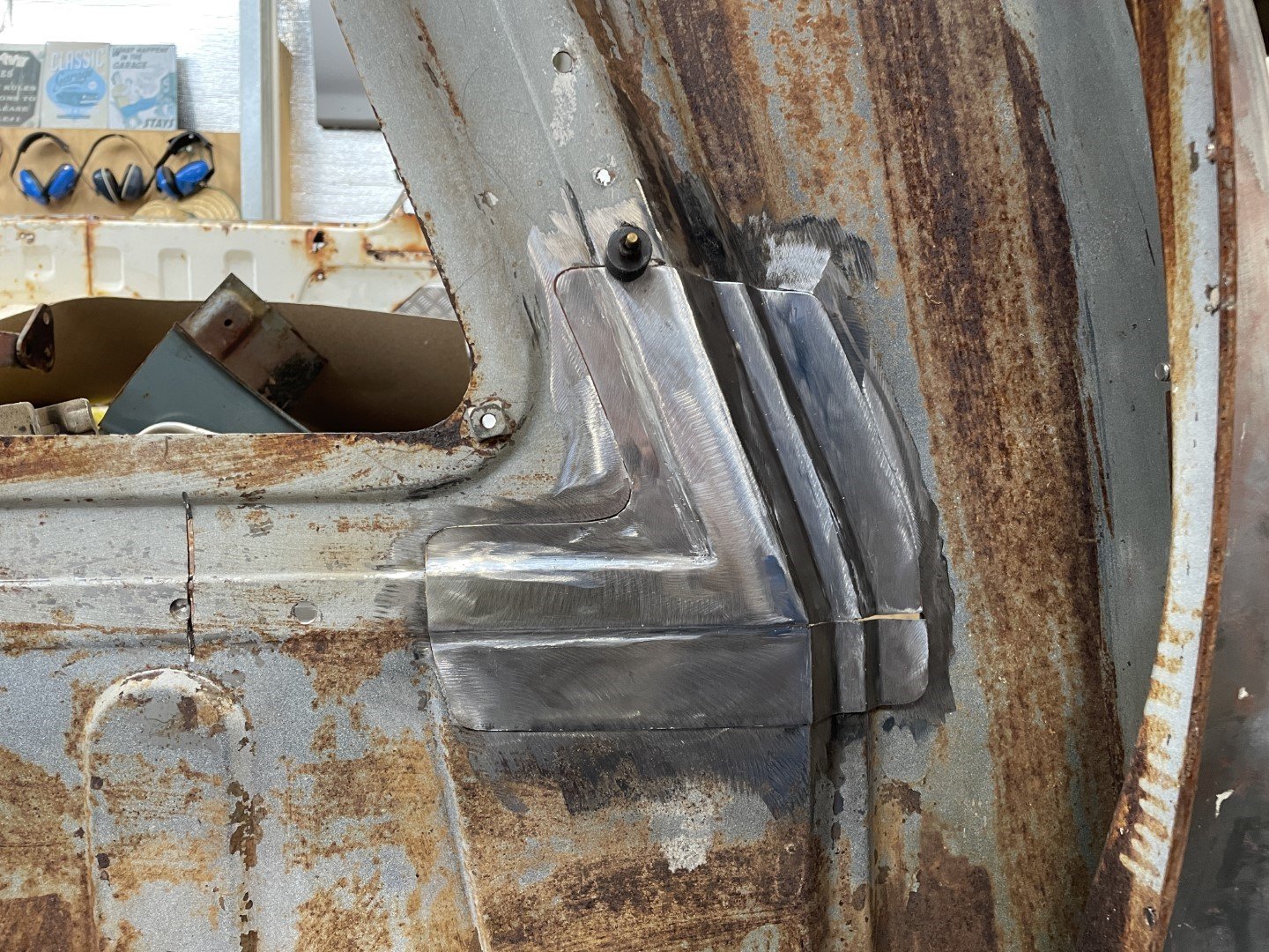
Just under an hours worth of hammering. Happy with the time investment.
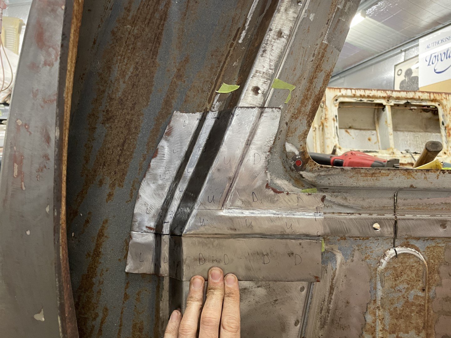
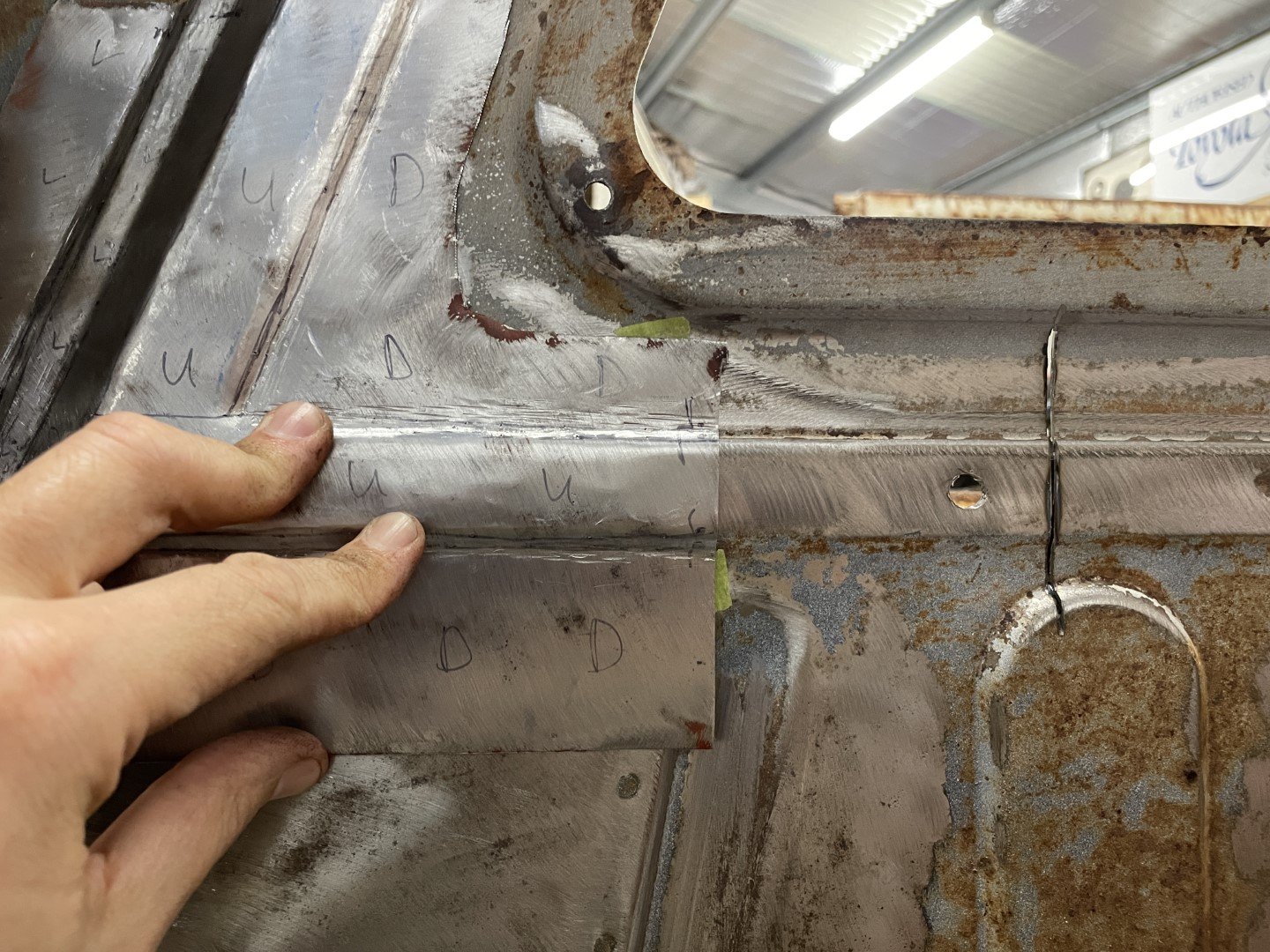
Relief cut needed some tweaking half way through hammering, but was pretty close to the money all things considered.
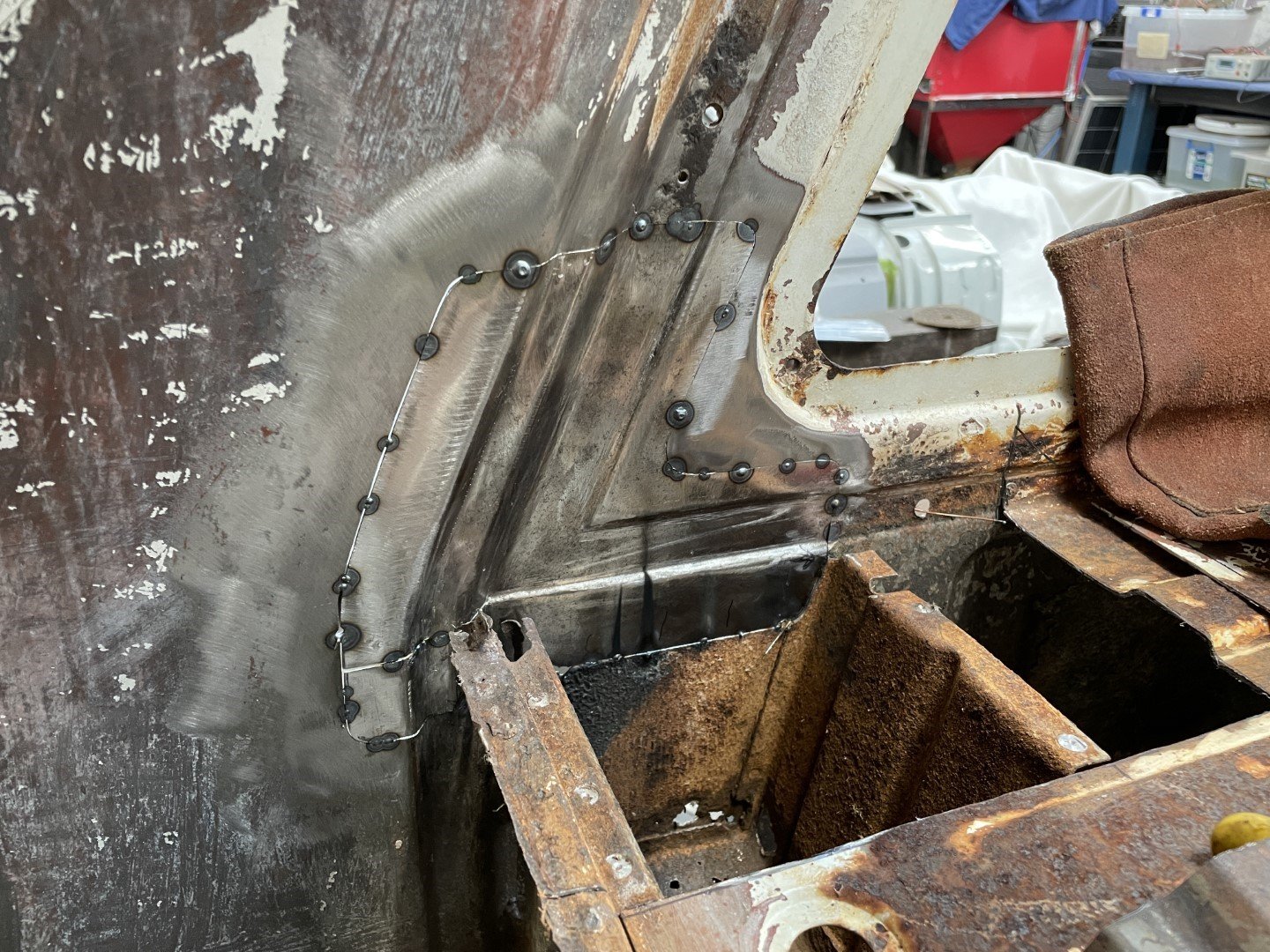
The step / relief in the panel shown here does need some work, but when I take into consideration that this side won't ever be seen again - and the inside will have the tray floor pan spot welded up to it I'm calling it good enough.
Pretty content with that fit. Stumps called, beer gathered and off to dinner.
-
33
-
1
-
- Popular Post
- Popular Post
Found some time to get out into the shed today - which had me (once again) staring at the shell of the ute and contemplating the enormity of the project I'd taken on.
Took my bitch pants off, put on some big boy pants and had at it.
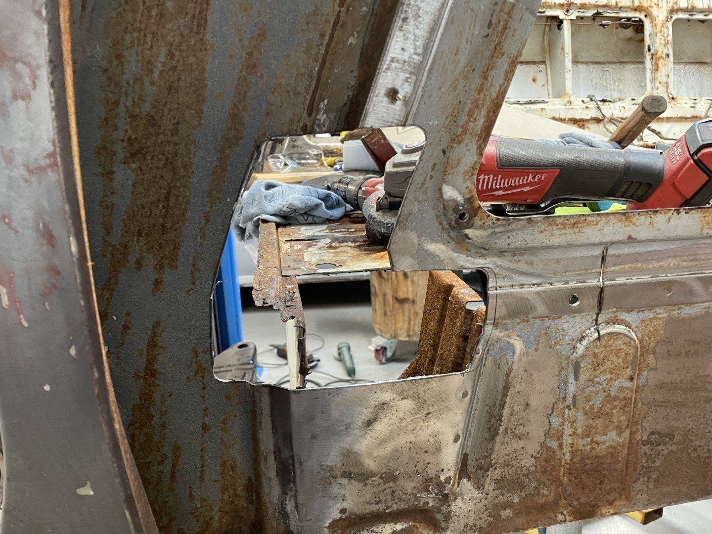
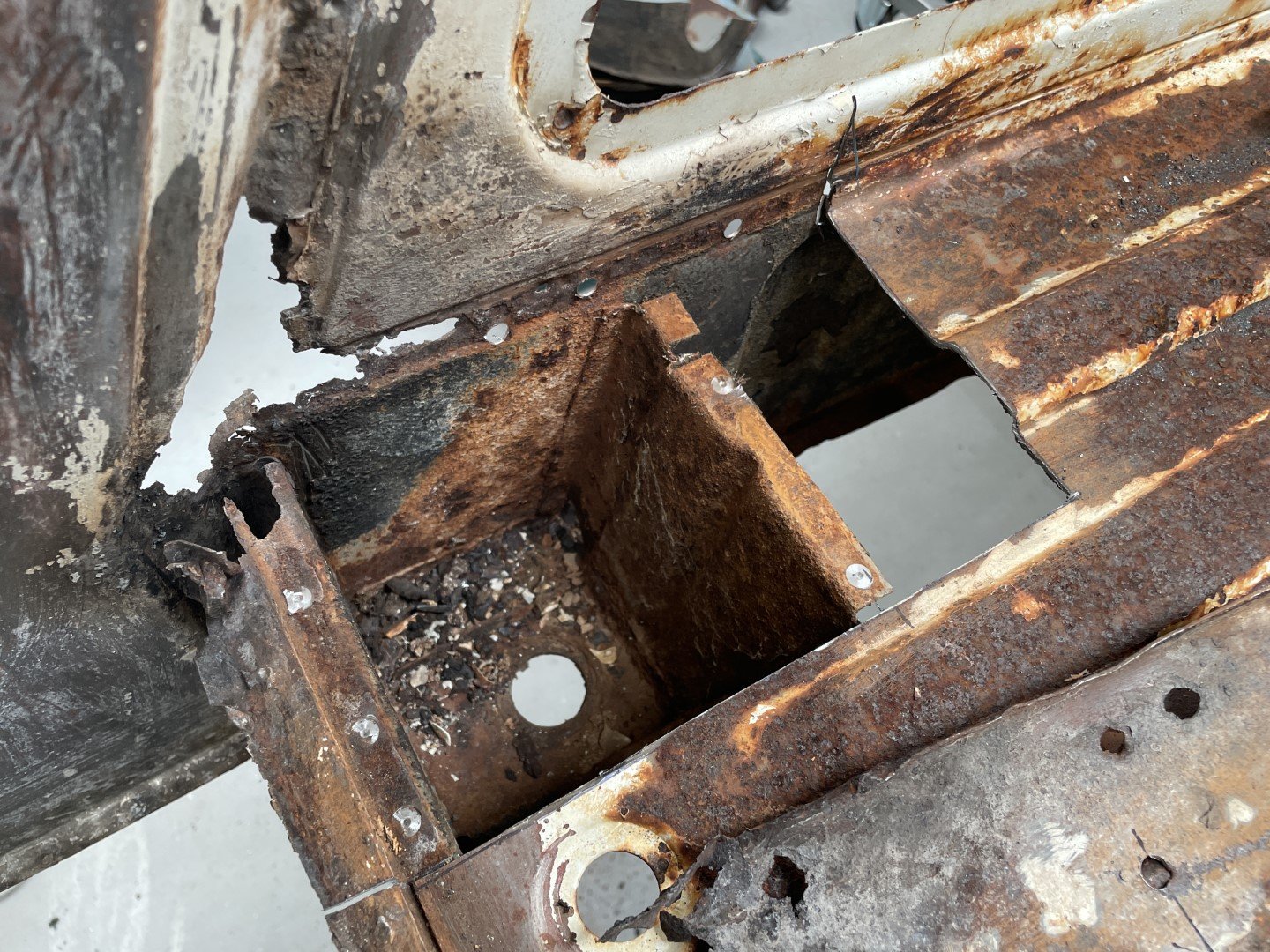
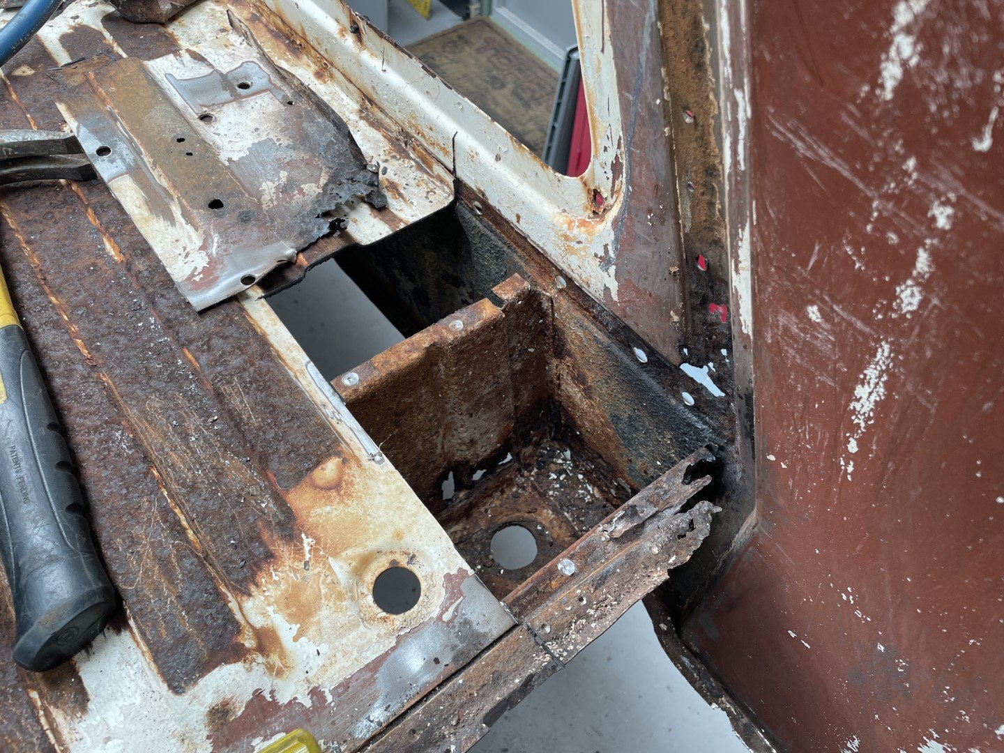
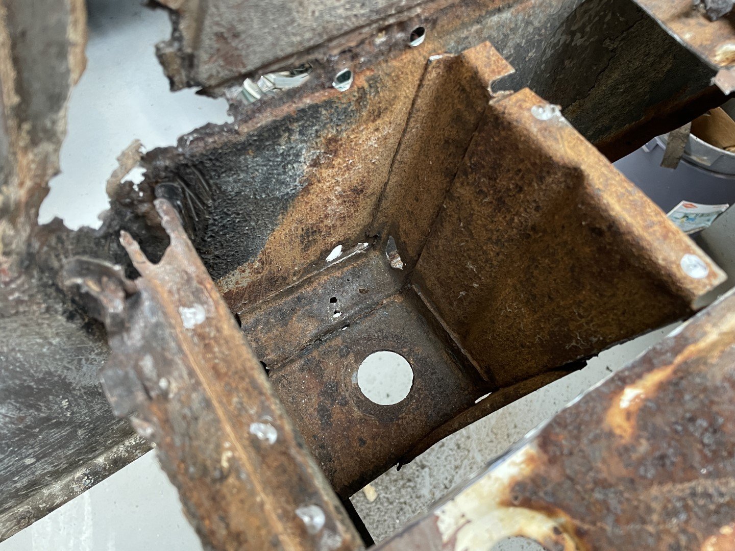
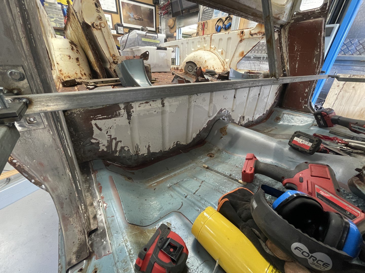
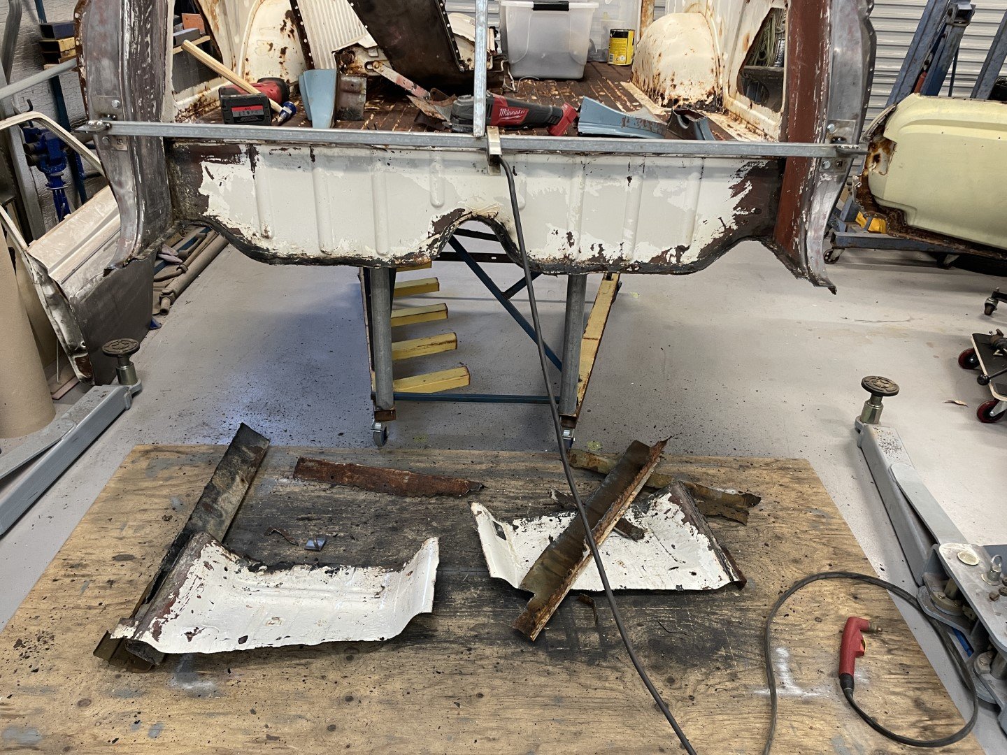
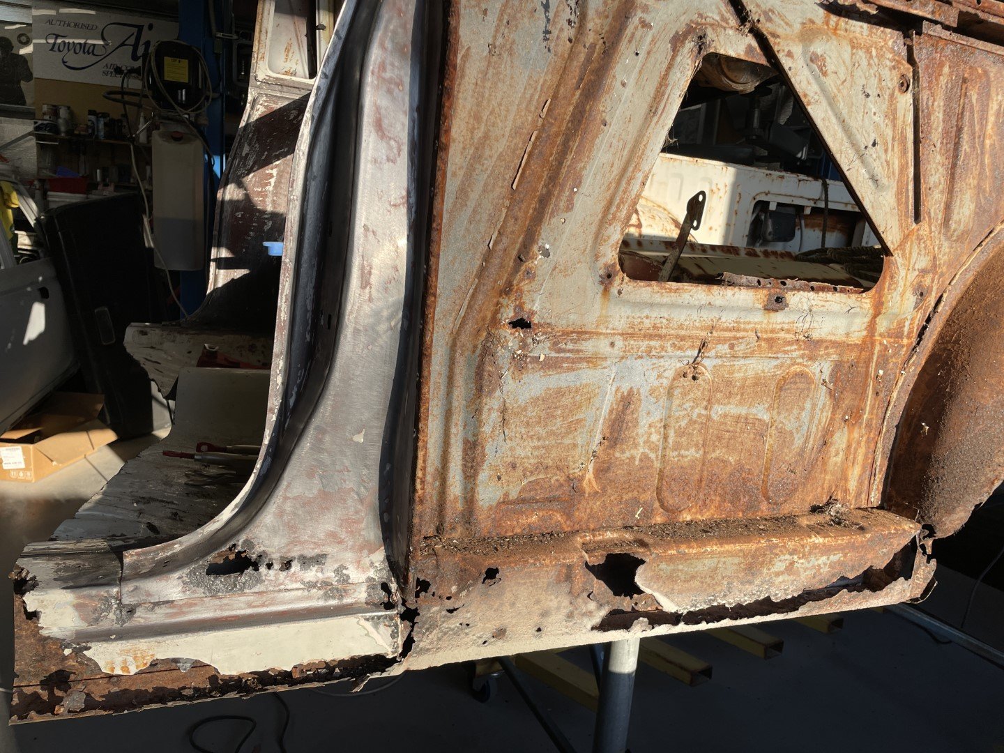
The front corners of the ute tray were giving me the most anxiety. I desperately want to stick the two halves together - but know deep down that avoiding these areas is just going to make my life harder later on when there's a floor pan in the way.
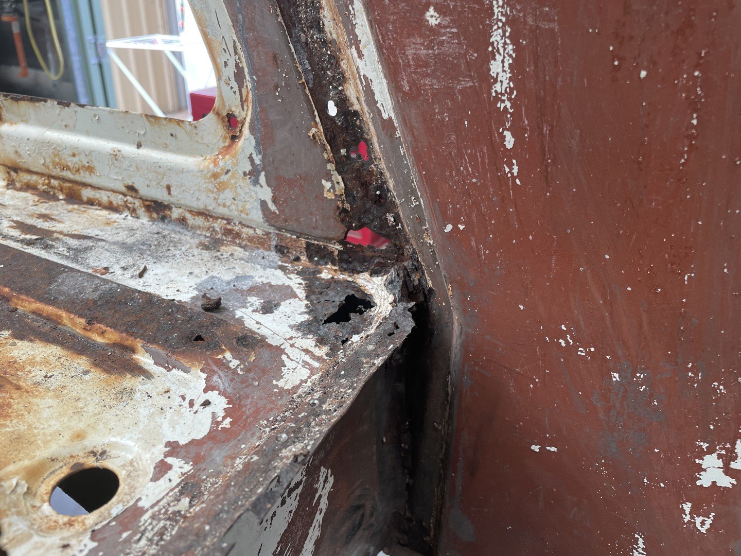
The passenger side didn't look so bad - plenty of metal still in the corner (in the grand scheme of things).
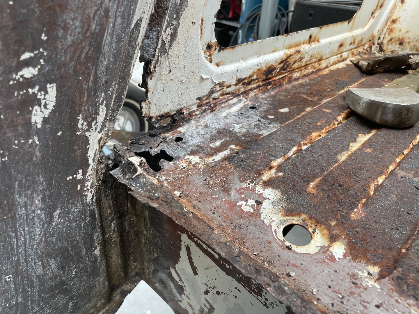
The Driver's side was considerably less good.
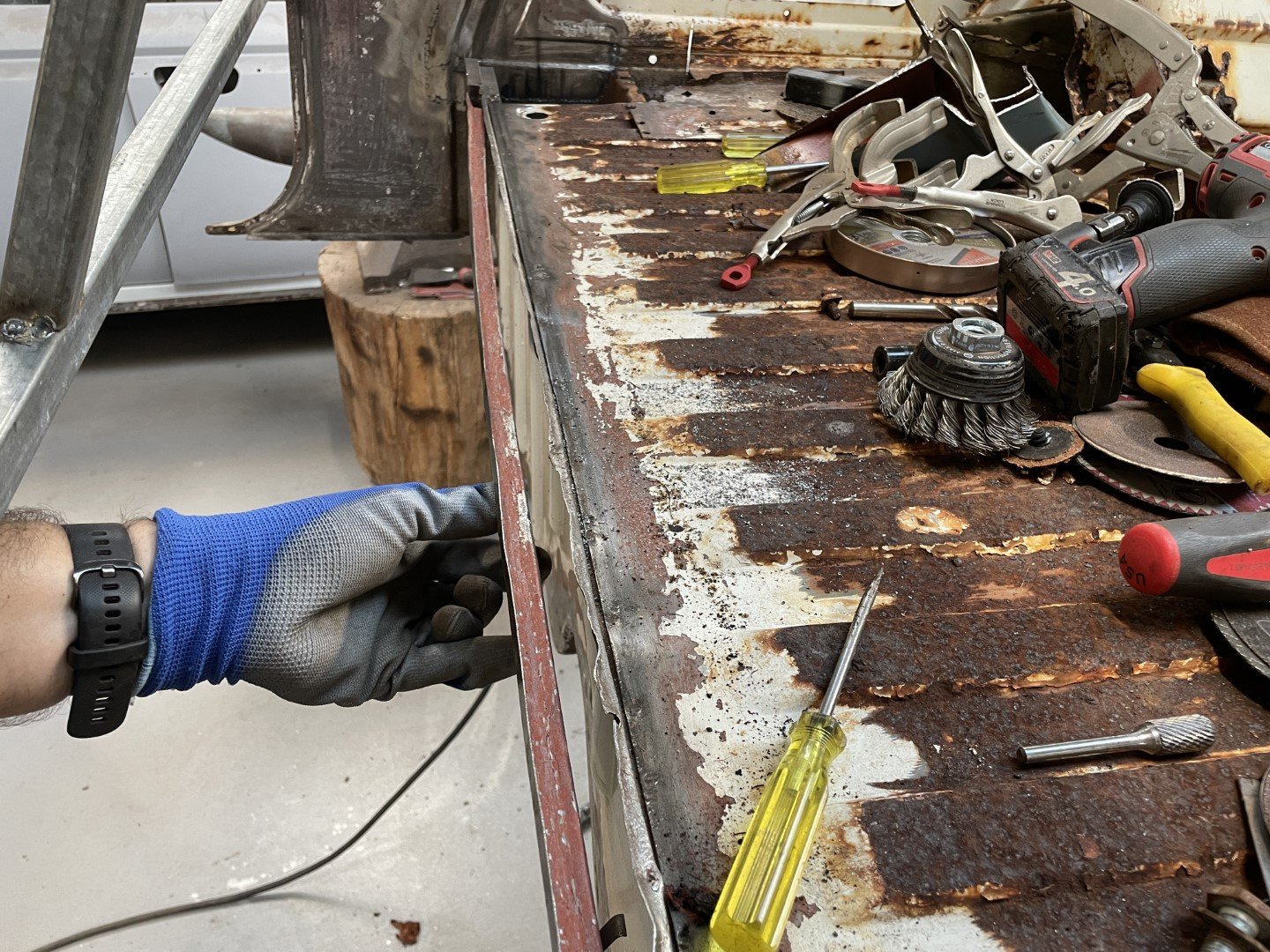
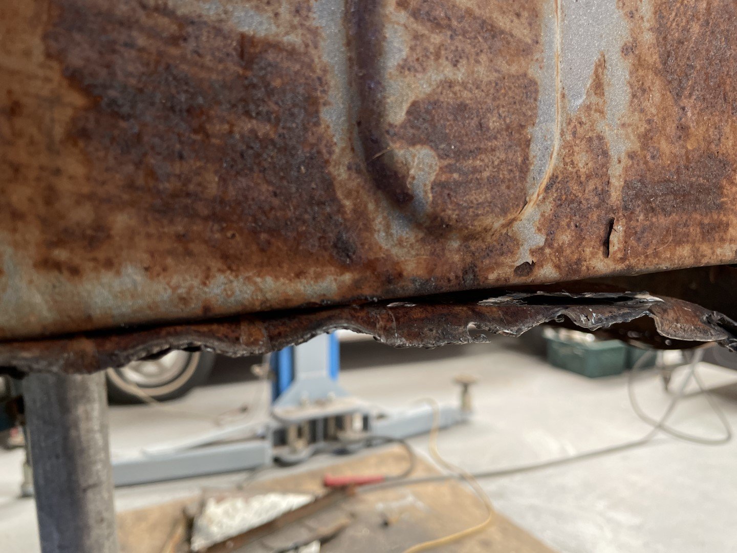
Figured the best place to start was to cut the floor pan corners out. Found the D/S forward tray mount to be in reasonable condition considering I'd blasted 10kg of clay mud out of there earlier in the build.
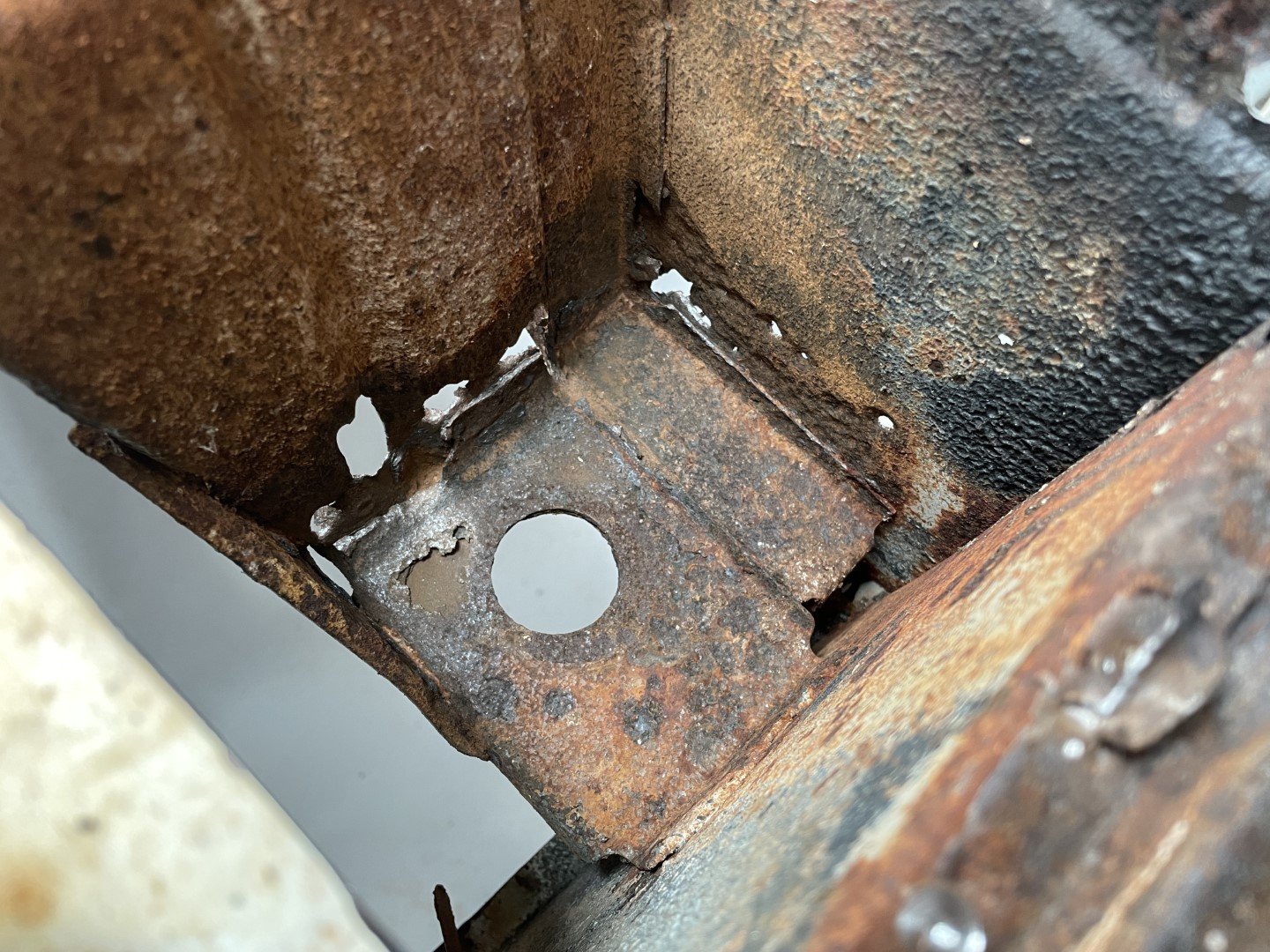
P/S forward tray mount was not as good - which was weird seeing as the upper section was in better condition.
Dug the needle scaler out of the depths of the garden shed to see how good it would be at knocking the rust out of the hole.
Did a pretty good job of identifying where the rust holes were.
Yuck.
-
11
-
- Popular Post
- Popular Post
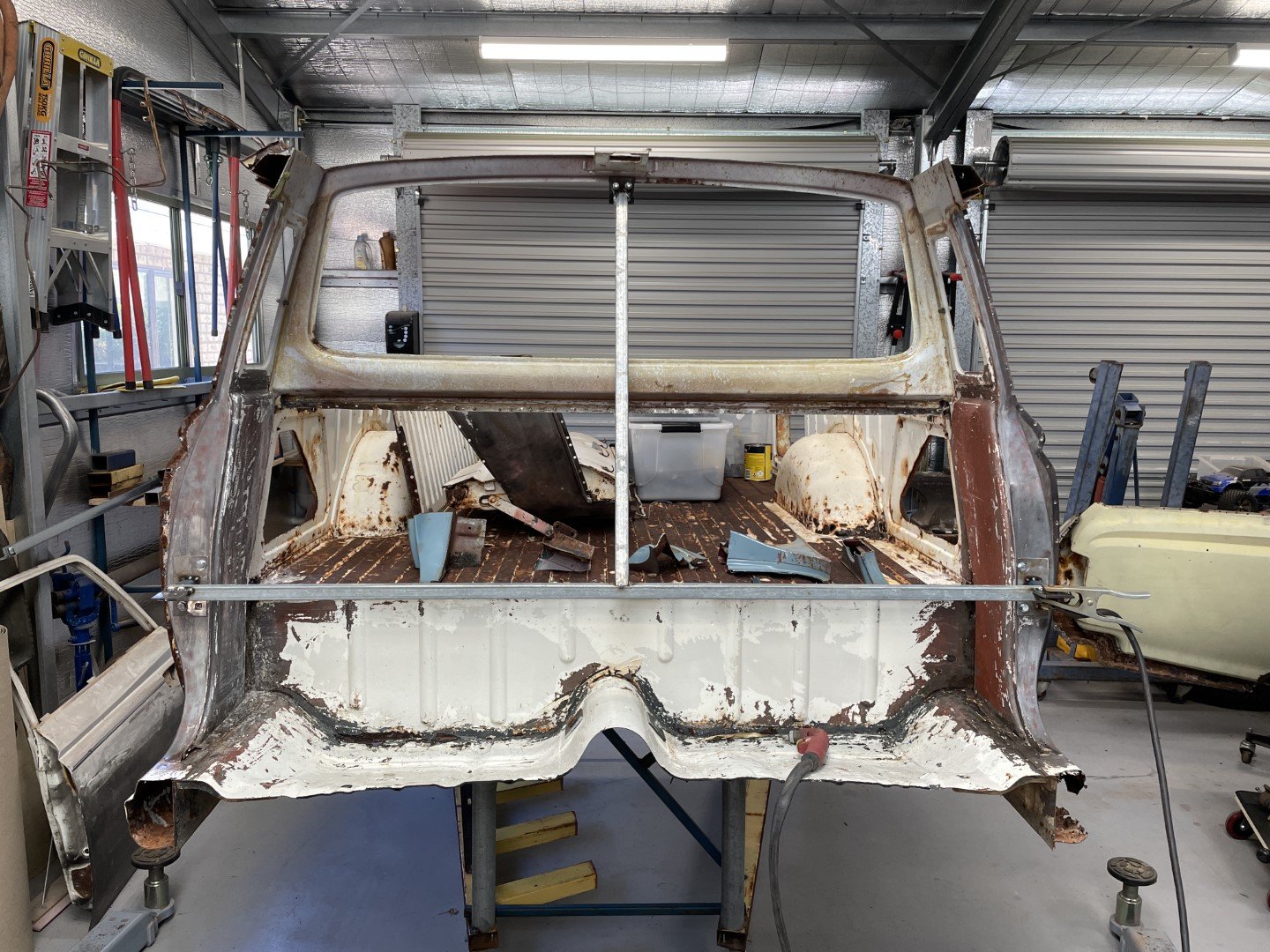
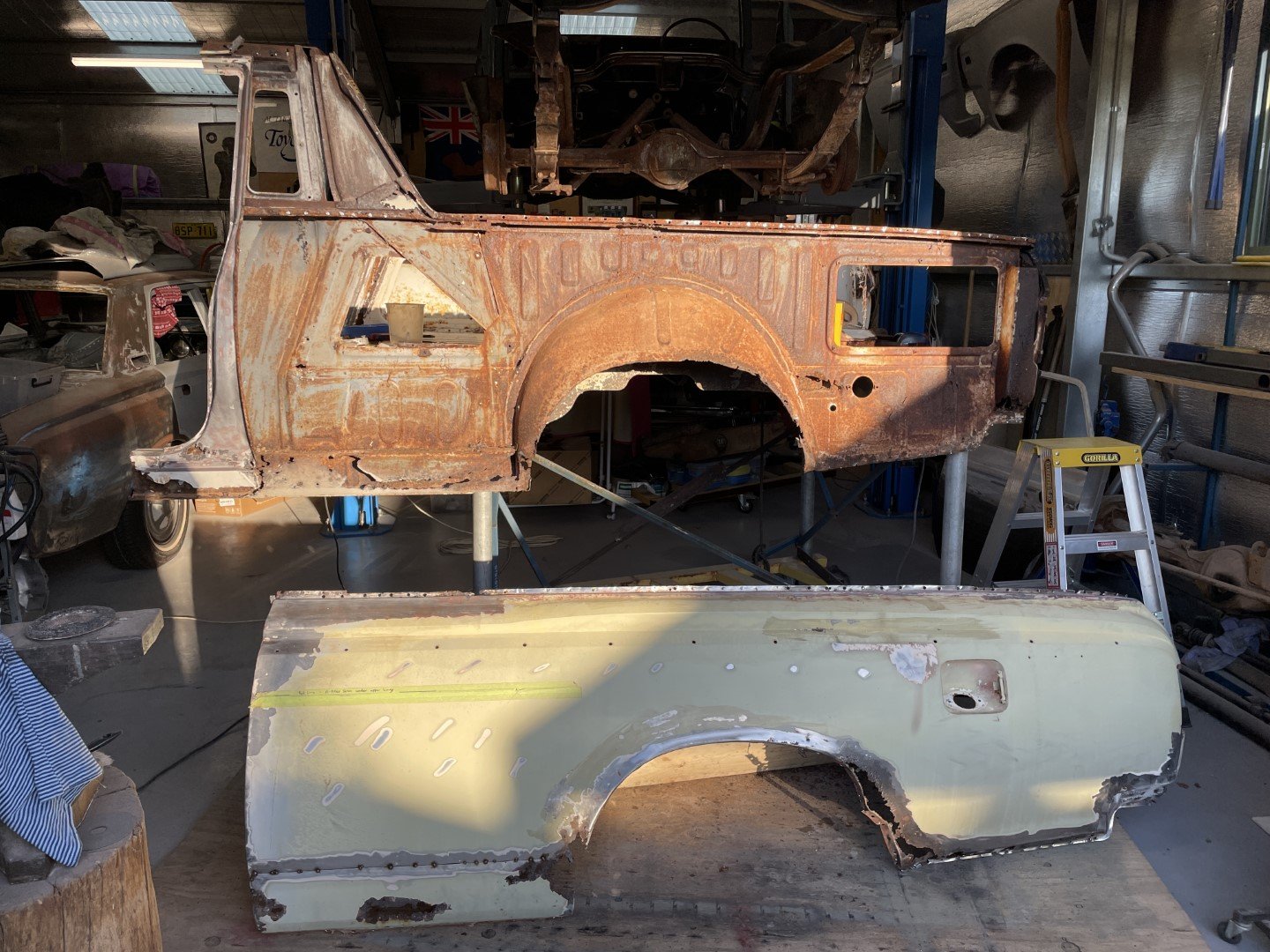
Forgot to add the glory shot of the two bodies sitting in the closest proximity ever. Had to fuck around as my plan of dropping the rear section onto the frame with the front section already in place fell apart due to come inconveniently placed chassis and body cross members.
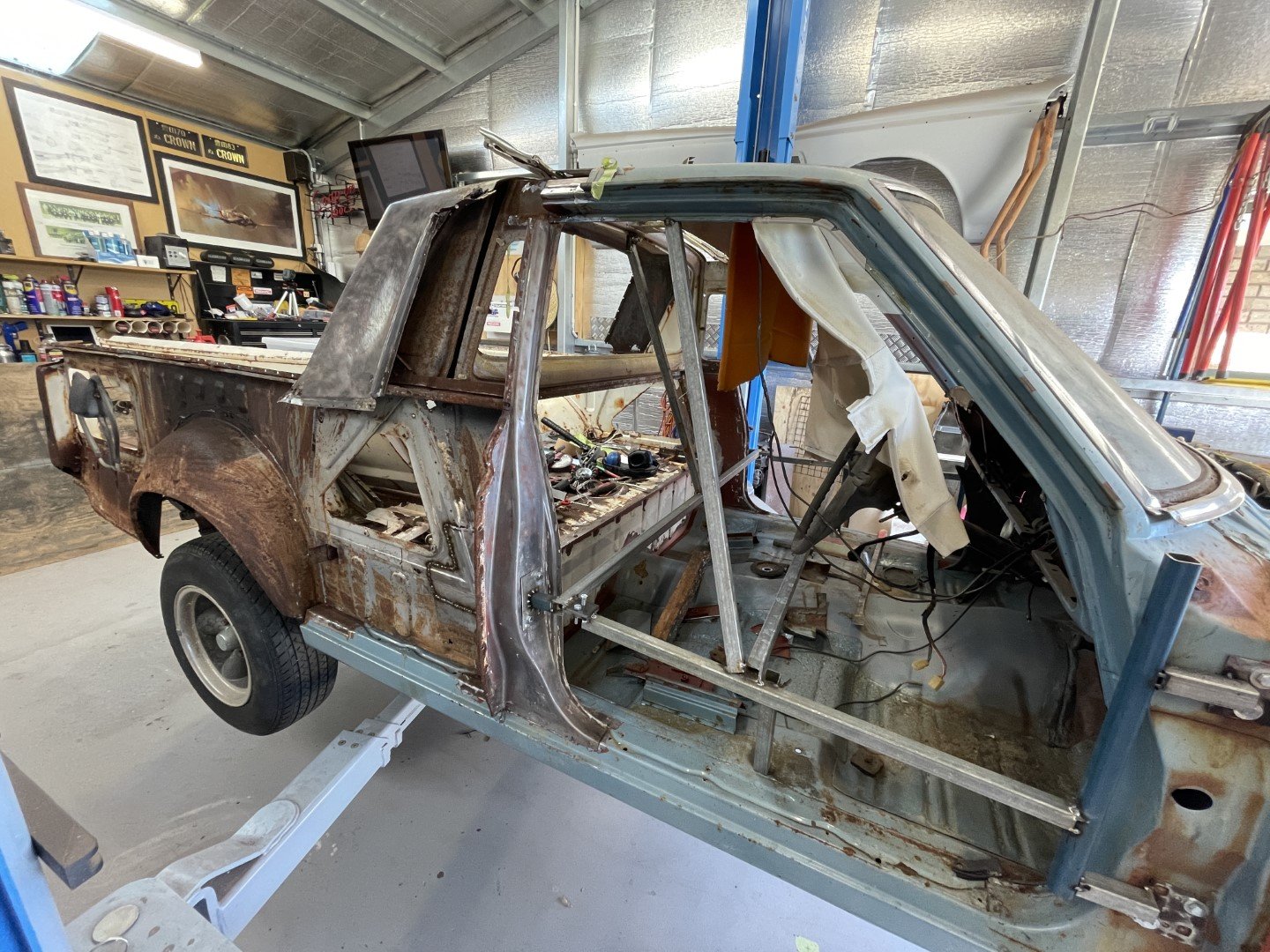
So back onto the trolley went the rear section - the hoist was then employed to lift the front section off the chassis.
Chassis wheeled out of the way, heights adjusted and the two pieces were slotted together.
I'm pretty fucking happy with that. Door aperture size is correct (measured against the closely available MS55 body parked right next door)
Rear firewall alights with the floor pan well (which was cut however many months ago)
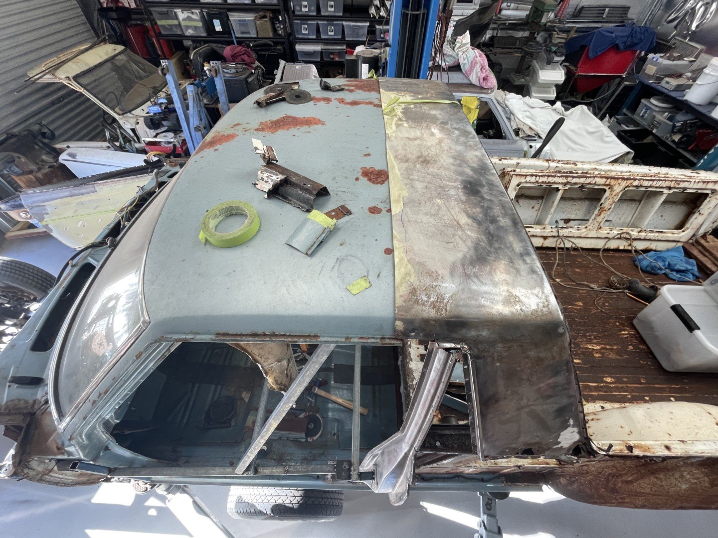
Grabbed the rear roof panel from the ute and sat it on top to make sure everything was heading in the right direction.
Stoked.
Still plenty of working out, measuring, cutting and welding (rust repairs more so) prior to sticking these two parts together - but progress is progress.
-
30
-
- Popular Post
- Popular Post
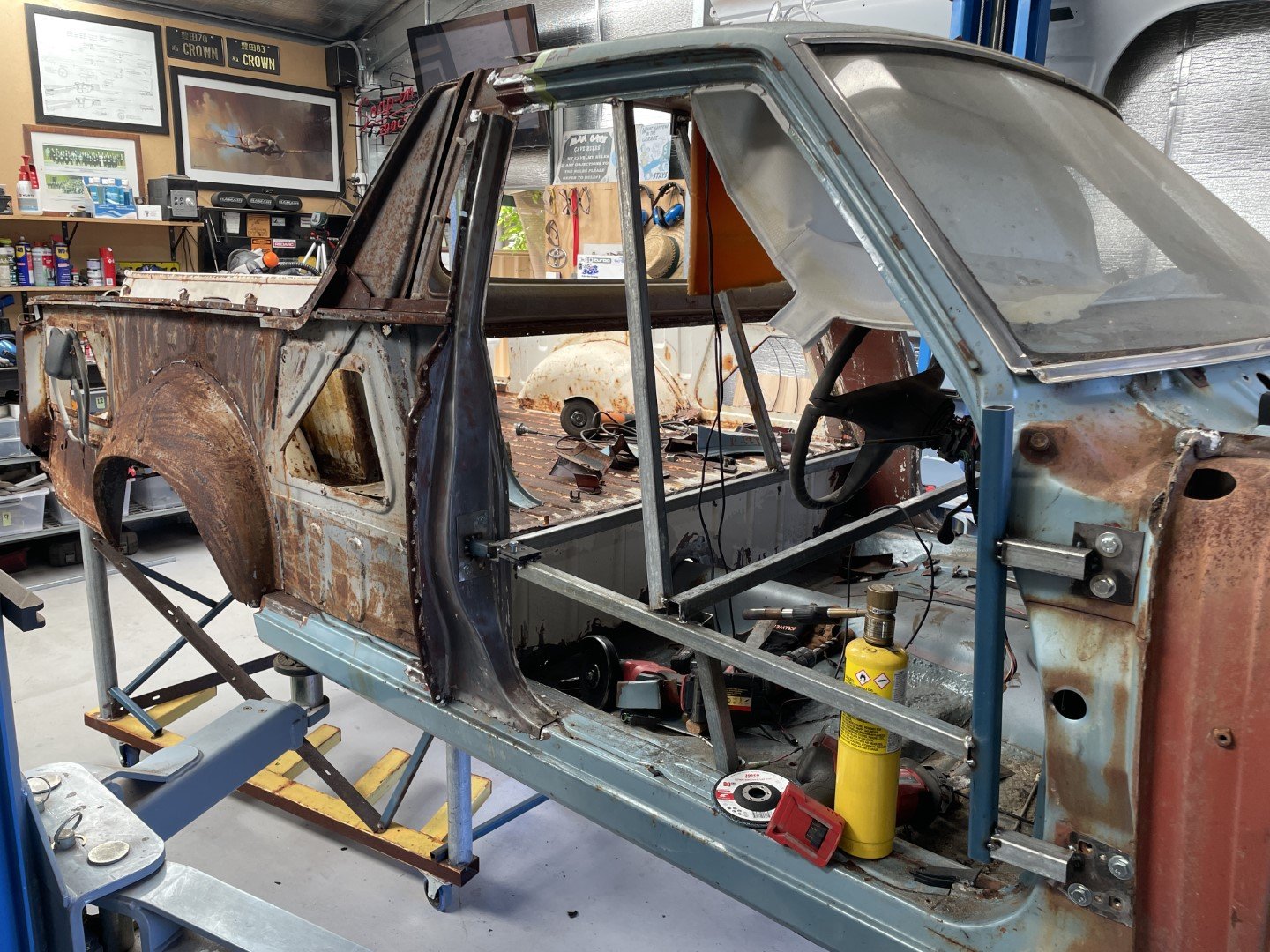
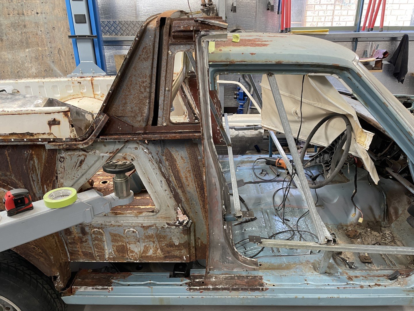
Spent quite a while staring at the intersecting parts to try and work out the best way of joining these things together.
My main goal is to stick them together in such a way that all connection points are identical to how it would have come from the factory all those years ago.
Not sure how many hours (or beers per hour) were spent staring at it - but it was quite a few.
Obviously the B pillar will sit where it needs to sit - but the roof junction was the part that perplexed me the most.
Stripped part of the roof panel off to get access to the inner structure. One thing that is clear to see is that this sedan has considerably better rust proofing / priming of panels prior to assembly.
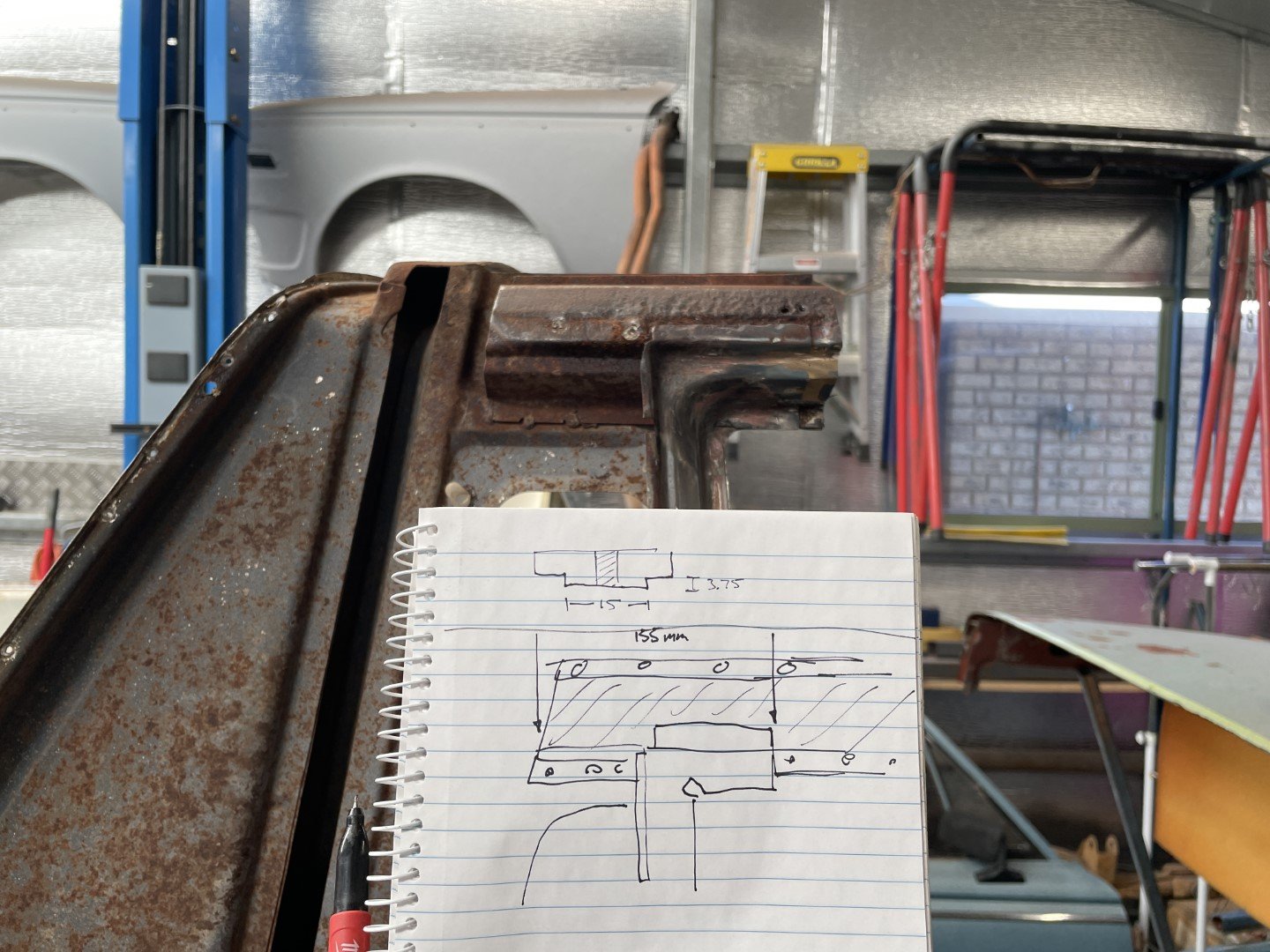
Made some detailed drawings of the B pillar structure / junction key dimensions on the ute for future reference;
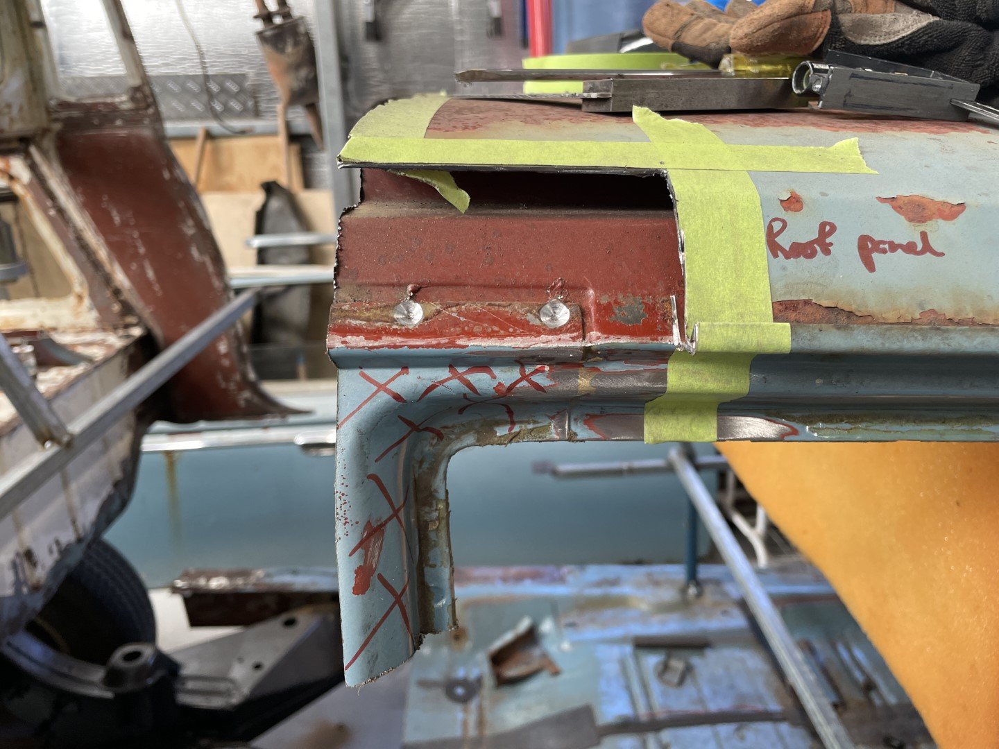
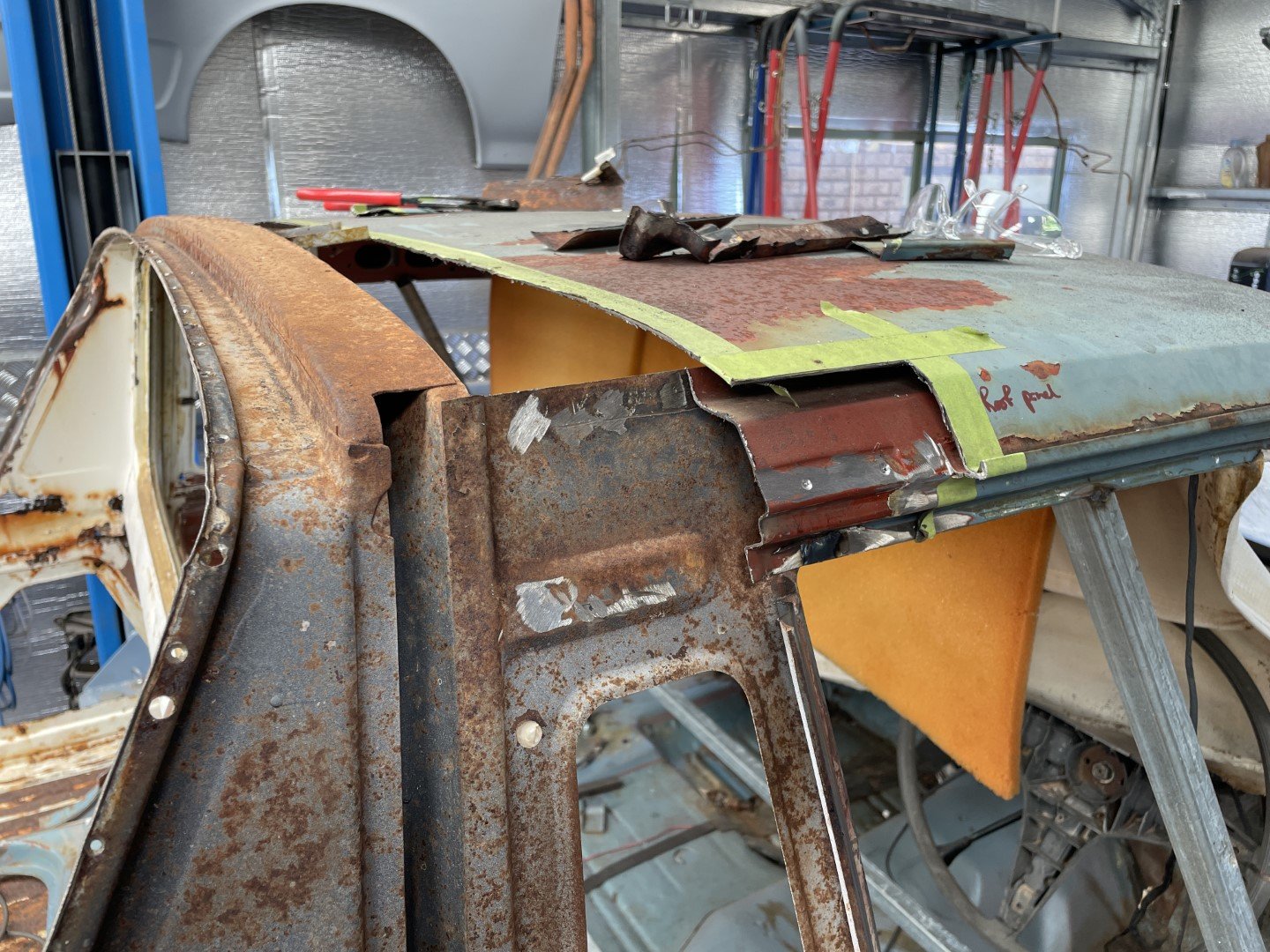
More hours of thinking and grinding saw the inner structure removed from the ute body. Had to cut the corner of the door aperture off to make life a little easier for myself.
Resulted in achieving this;
From the photo above the intersecting parts become a little clearer. The two pieces of the inner roof structure overlap. Just need to extend the outer part of the inner structure to match the engineering drawings I generated earlier in the day.
Nice to find that the door aperture corner that I had to cut out earlier still fits (some fettling required, but close enough for me)
-
20
-
- Popular Post
- Popular Post
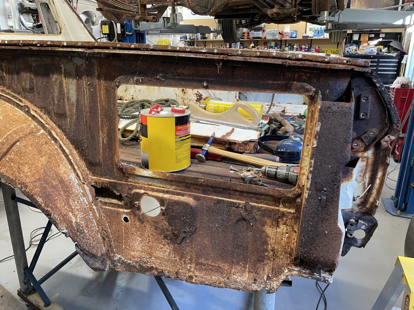
Now that the sedan parts were all cleaned up, it was time to move on to the ute part.
Figured that since I had a plasma cutter laying around doing nothing that I should employ it to remove the shittier parts of the back half.
After fucking around trying to get it to work (been too long since I used it) and additional side quest of fitting vibration dampening feet to the air compressor I managed to get rid of the less necessary steel.
I wish that had been the hard bit.
But it wasn't.
A considerable amount of time then went into grinding the remains of what was once sheet steel that was spot welded to the back half.
Just. Shitty. Grinding.
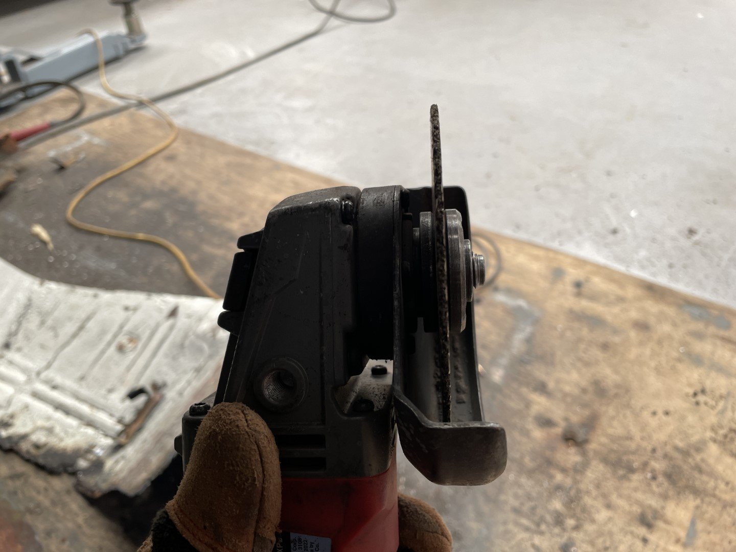
Actually found a use for these stupid 'cutting' discs though. Spot weld grinders.
Just. More. Grinding.
So yeah. Hours of grinding.
Didn't really look like much once I'd finished - so in a mad dash to source some dopamine before I had to pull up stumps, I moved things and stuff around in the shed to lift the ute body off it's trolley.
Closest it's been to being one car in. Well, forever.
-
21
-
Sawzall employed, B pillars subtracted from the sedan;
Then much cutting and grinding to remove B pillars down to the sills - so much crusty shit sitting down there.
B and C pillar remnants removed;
As a side quest, the original doors, fenders and rad support from the blue sedan became available - so I blew even more money and collected them.
I'm selling it to myself as a 'you could get this thing finished so much sooner now that you don't have to paint fenders that blue colour!'
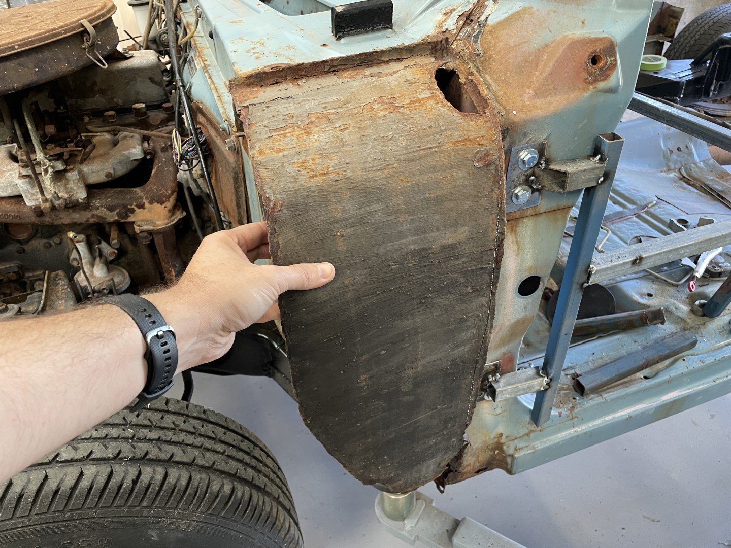
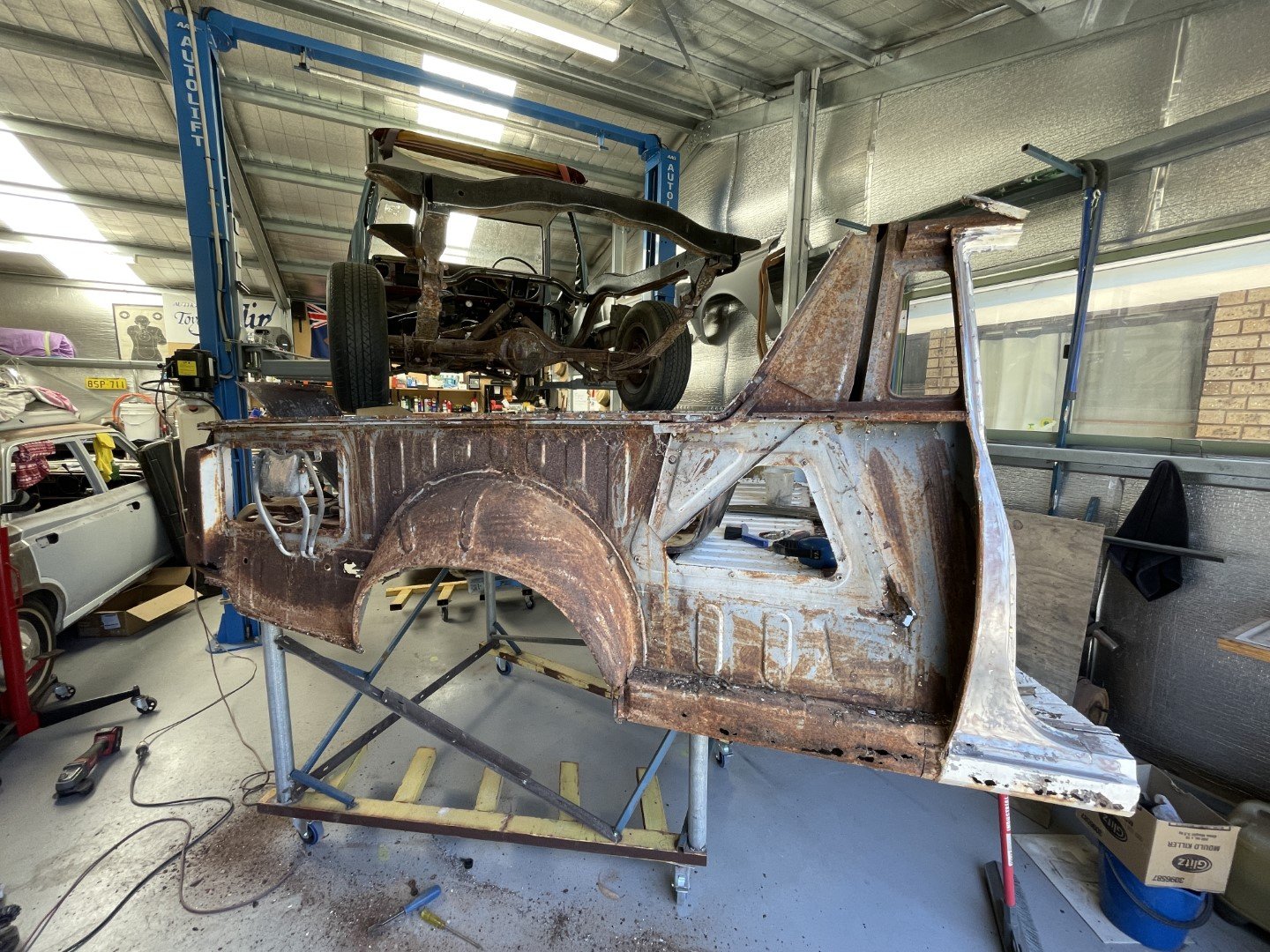
Very much extra good side shown there. The other side is fucked though.
Not badly fucked - but just enough for me to have to perform more surgery.
Overall - the LH side of the sedan was the worst - would have to have something to do with it's collision history - see le shitty plenum end photo below.
And then underneath.
fucking blergh.
-
8
-
-
- Popular Post
- Popular Post
So somehow it's now the tail end of March - how the hell did that happen?
Progress has been slow - but progress made none the less.
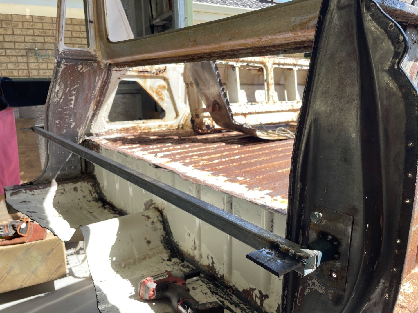
Figured the best thing to do next was fashion some kind of jig that would allow me to throw these two cars together into, well... one car.
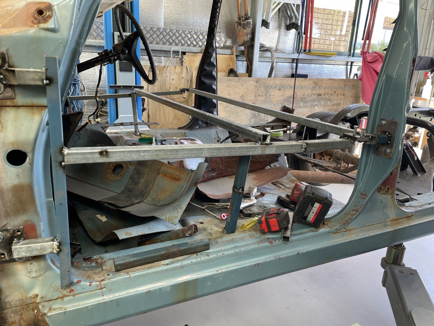
A frame was considered and then built that would locate (what I feel) are key dimensions - the distance from the A pillar to the B pillar.
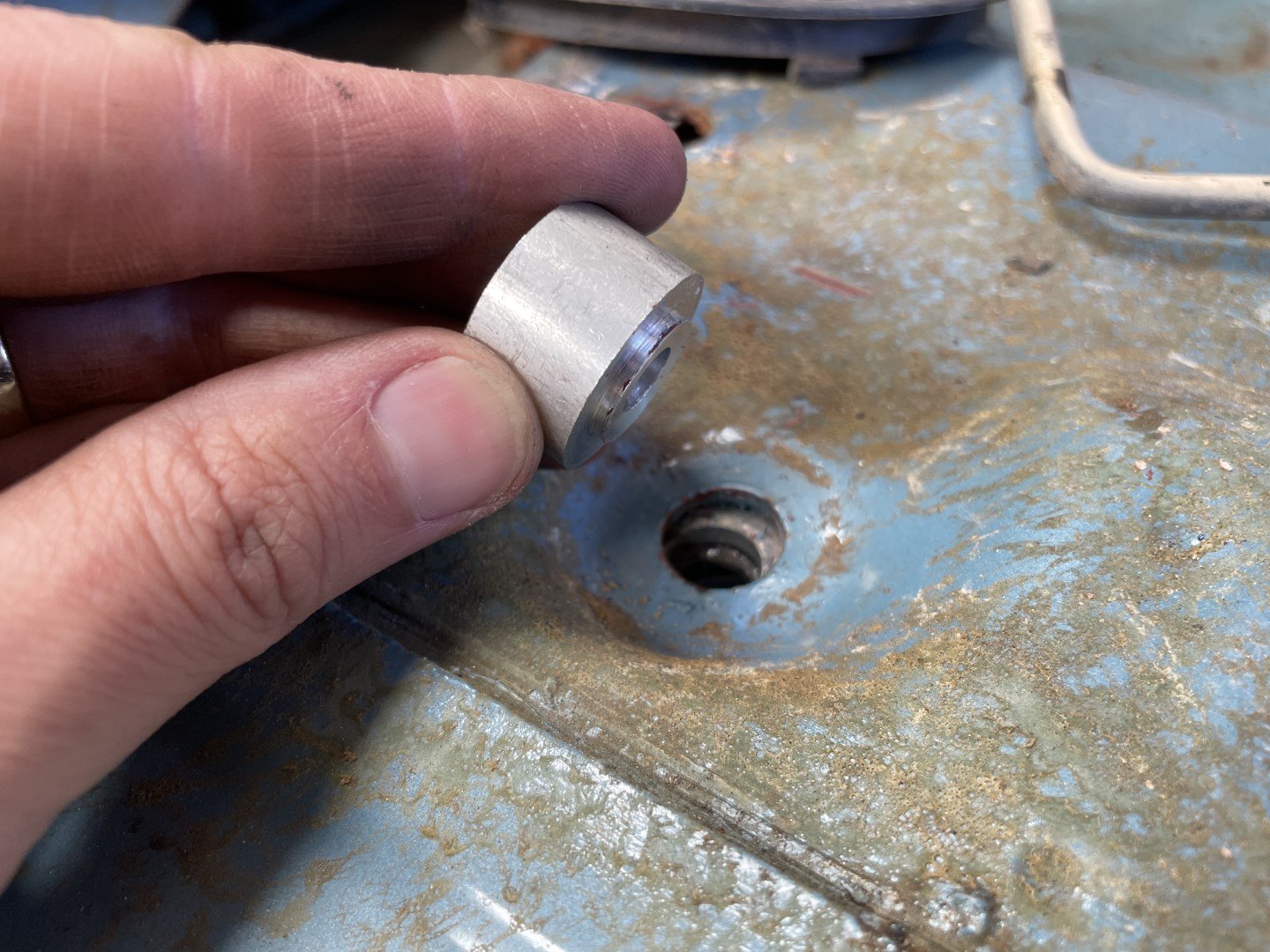
So I spun up a couple of threaded plugs that would locate to the floor pan;
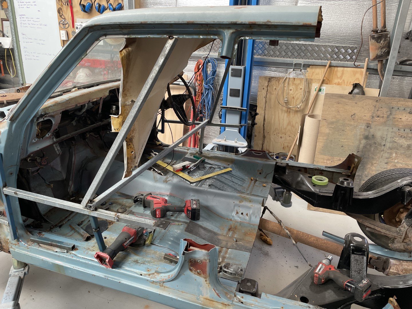
Then proceeded to weld in bars to plates that I could locate on the door hinge and door striker bolt locations;
I made the pieces that locate on the B pillars removable so that I could cut the pillars out.
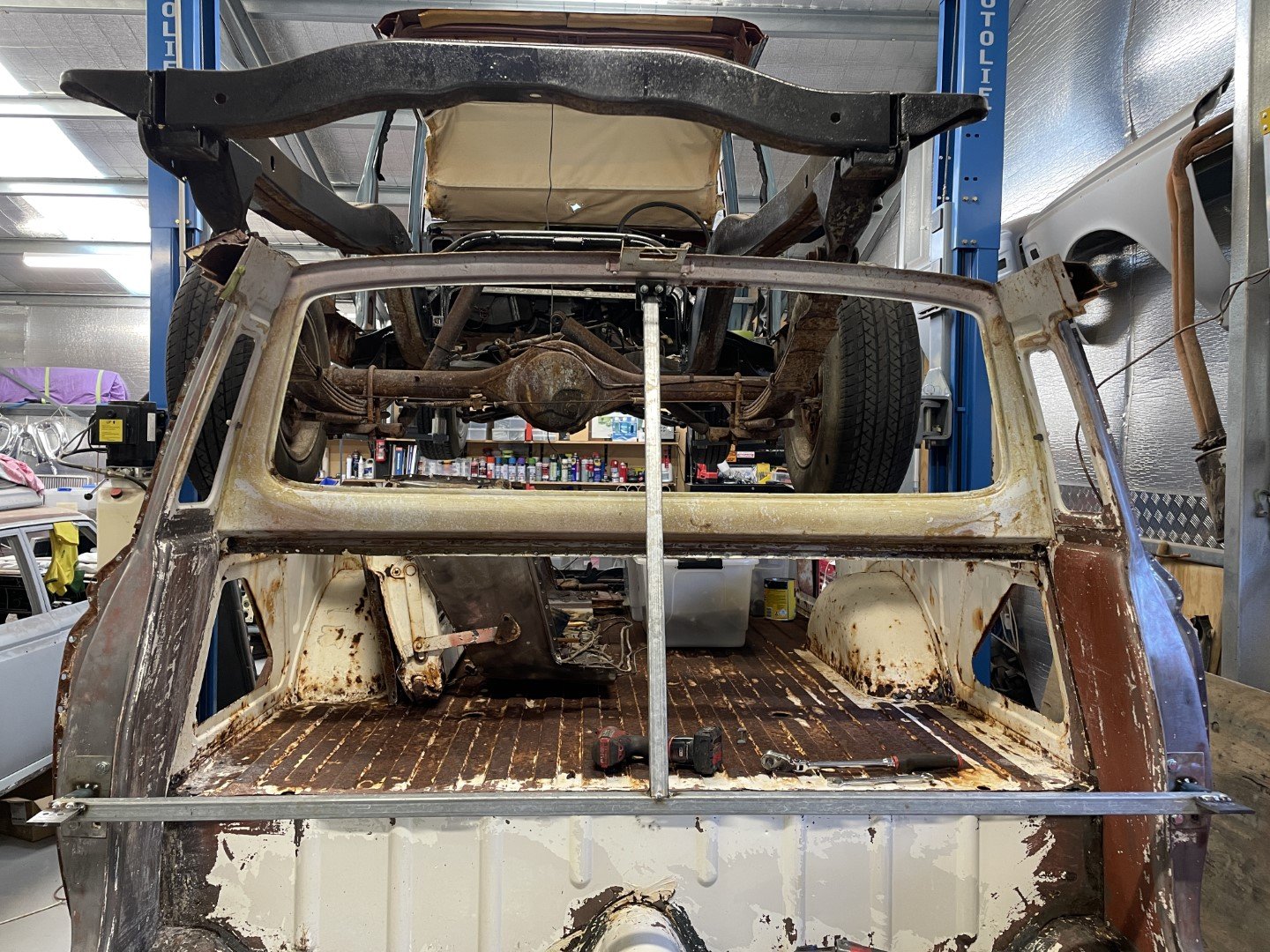
Added an extra brace from the middle bars to the roof and then one between both sides.
Bolts out - nothing moved which told me it was sorta okay-ish.
Then took the B pillar bar and checked it against the ute B pillar. Holes lined up which was nice.
Added an extra brace from there up to the rear window aperture to make me feel more comfortable about its position in space;
-
10
-
- Popular Post
- Popular Post
Basic update because very little has been achieved in the last month.
Between family holidays, work and other commitments this thing has been no more than something to stare at in the couple of minutes spare i've had.
Anyway - boo hoo for me.
Ripped into the RH side 1/4 panel to see what scary things lurked behind. Much better than the LH side which is nice.
Additionally, I take back all the nice things I said about the proper spot weld drill bit that I purchased.
It was nice for a while, but after a while - not nice.
Stupid think got all tuckered out after drilling 50+ spotwelds - and refused to drill any more.
Tried to sharpen it with the angle grinder - and fucked it.
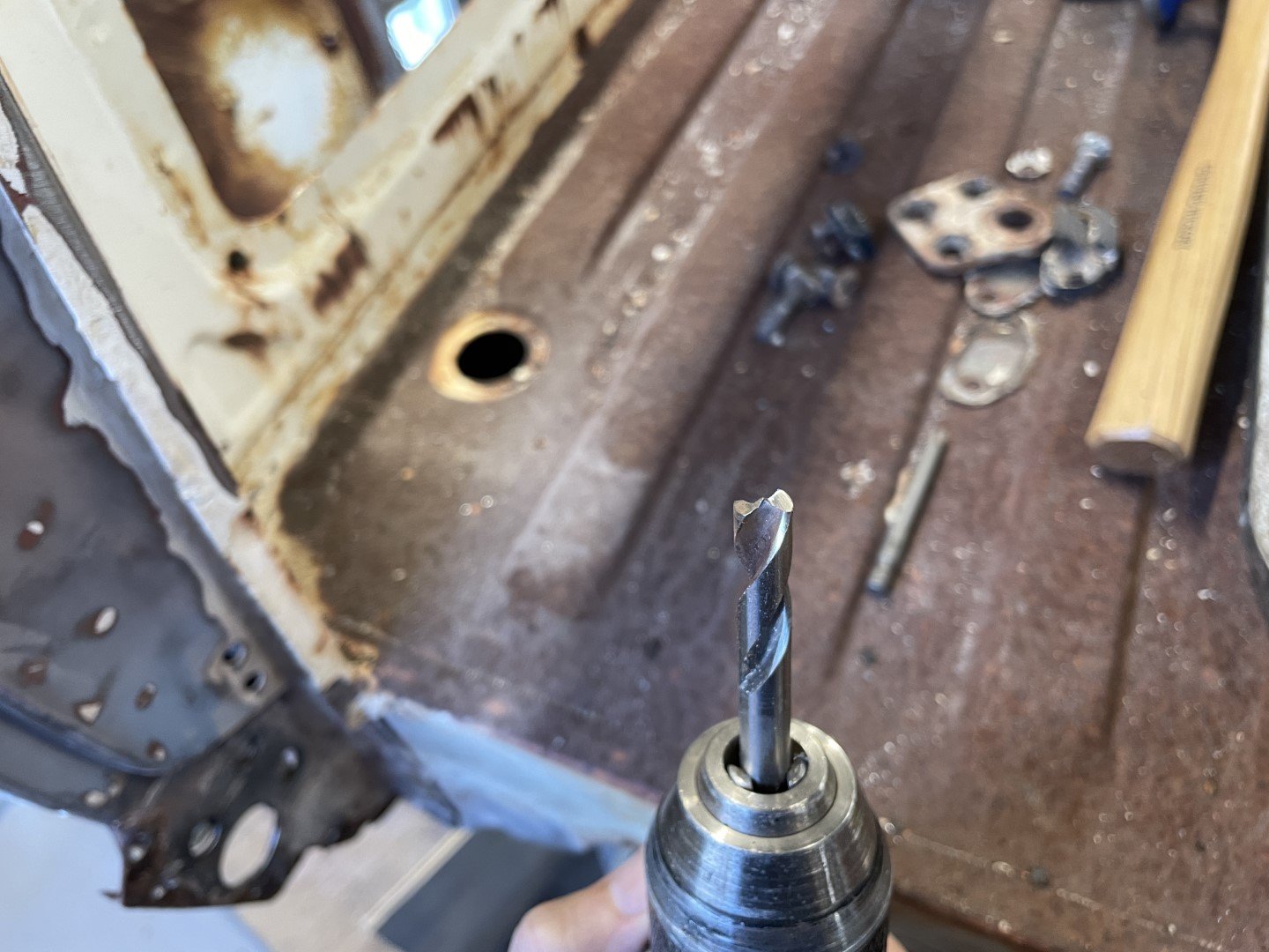
Tried the next best thing - normal drill bits. Been here and played this stupid game before - and it wasn't fun.
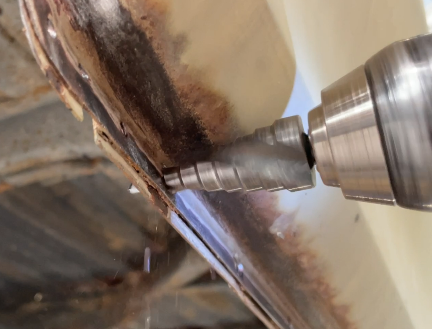
So, after going around with a 4mm drill bit to 'spot' the welds, I gave an old Uni-bit a try to see what would happen.
It was much better.
Considering that I was working within a short window of time, all give-a-fucks had gone right out the window and I wanted this panel off yesterday.
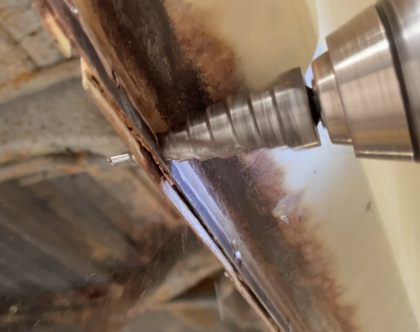
Initial screenshot of a video shows the Uni-bit tearing this panel a new one - notice very little gap between panels.
After clunking through a couple of steps - the panel gap opened up signaling victory!
Happy days.
Carried on with the remainders and got the panel off using considerably less finesse than that used getting the other side off.
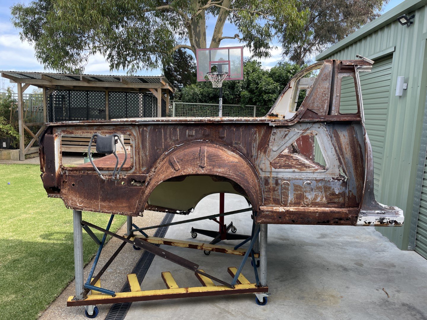
Wheeled it outside and pressure cleaned the snot off it and let it dry off.
Then pushed it into the shed so that I could resume normal fatherly duties.
-
24
-
Thanks dude - I'm super happy with the plating. Glad I spent the coin and bought a decent kit, as the results have been pretty much perfect from the start.
The vapor blasting cabinet was conceived after watching nearly every video I could stand to watch on YouTube - and then just worked out what I thought was best in terms of construction.
Bought the cheapest dirty water pump I could find to move the media, built a hand piece using plumbing pieces and controlled the air with a water inlet valve I took out of an old dishwasher (which was basically just a 240v - so a 12v / 240v relay was employed to supply 240v to the solenoid whilst being controlled by a 12v foot pedal)
It uses bulk air because my nozzle design is less than efficient - but it gets reasonably good results for a piece of equipment that I smashed together and abandon in the corner of the shop for months at a time (or sufficient time for most of the water to evaporate out of the bucket underneath)
-
1
-
-
- Popular Post
- Popular Post
Treated myself to a proper spot weld drill bit - really wish I'd done that sooner.
Probably could have ground a normal drill bit to work in a similar fashion - but I'll worry about that once I ruin this one.
I set about getting access behind some other panels.
It was hot.
Like, fucking hot.
Because I've filled my shed with so many cars and parts, I'm working up against the roller door that is on the Western side of the building.
With the sun having shone DIRECTLY at said roller door since 1pm, it was now a giant radiator. Yay.
Anyhoo - after nearly an hour of drilling I was covered in swarf and sweat, but had achieved a thing.
I'm super glad that someone had made it look somewhat pretty on the outside - because it's fucking ugly underneath.
I'm starting to think that it might be a good idea to see what it'll cost to blast all these inner panels....
-
21


MS51HT's RS56 Crown Ute
in Projects and Build Ups
Posted
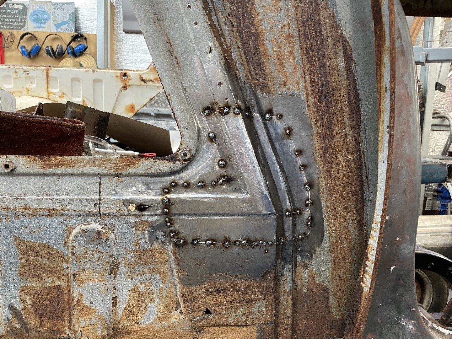
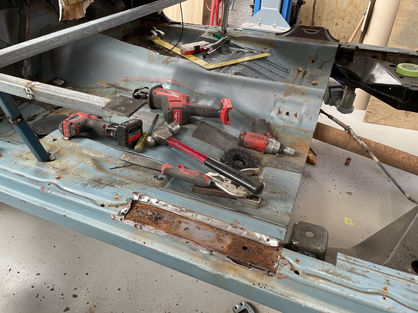
Tacked the lower mounts in and confirmed for the final time that they were in the right spots.
Fully glued them in.
Gave the frame a wire wheel and threw some primer at it.
Then got the 'used car overhaul' spray gun out and blended it all in.
Happy with that.
While the paint was drying I fitted a new clutch slave cylinder and made up a fluid hard line that located the flexible line on the RH side of the cylinder head as per MS55.
Weekend done - hopefully I'll get a change to sling the engine in during the week so I can feel a little more accomplished.