


The Night Rider
-
Posts
57 -
Joined
-
Last visited
Posts posted by The Night Rider
-
-
I'm wrecking a manual AW btw
PM sent. Thanks.
-
- Popular Post
- Popular Post
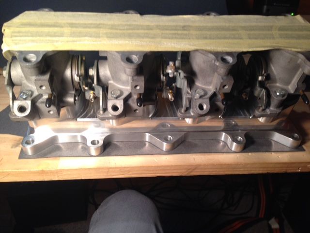
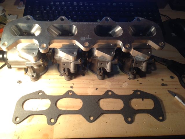
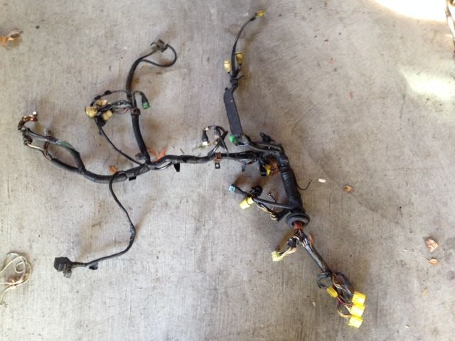
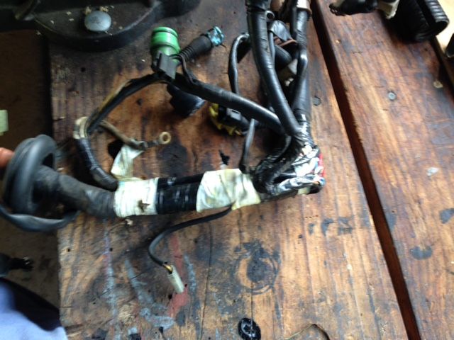
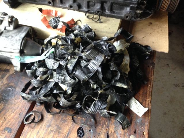
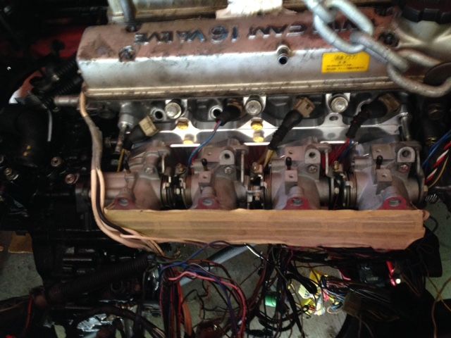
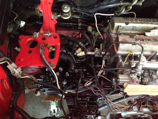
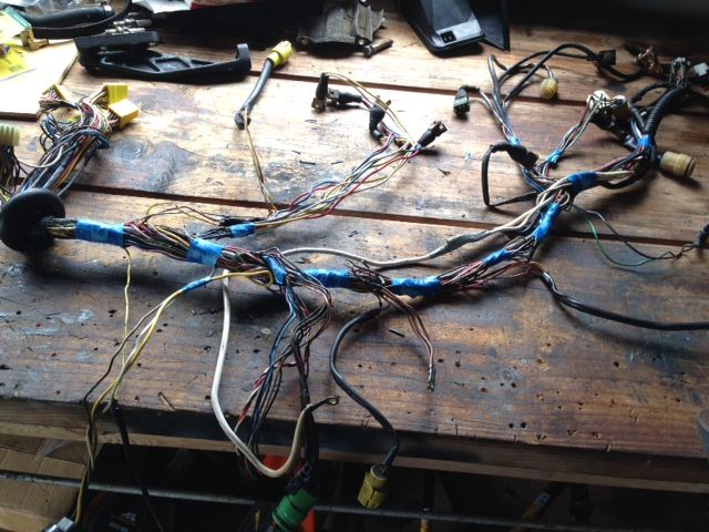
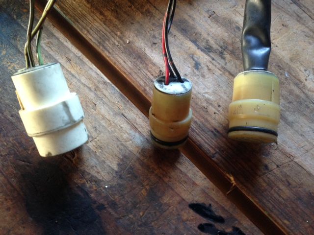
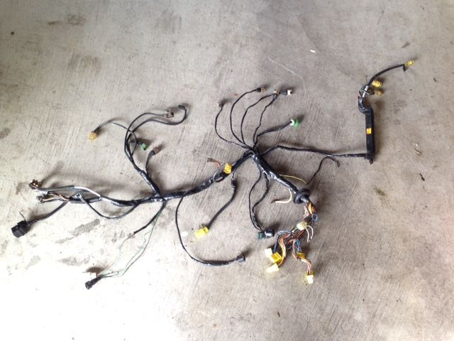
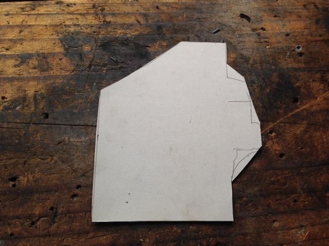
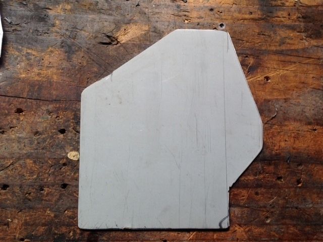
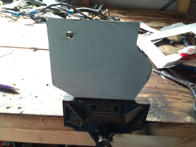
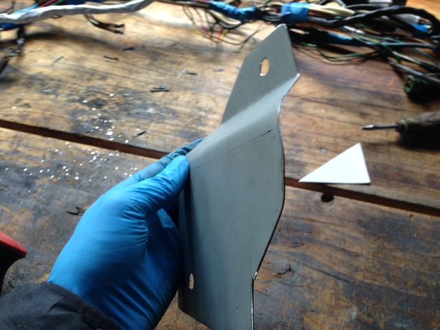
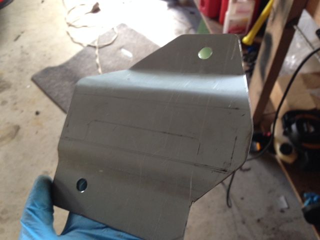
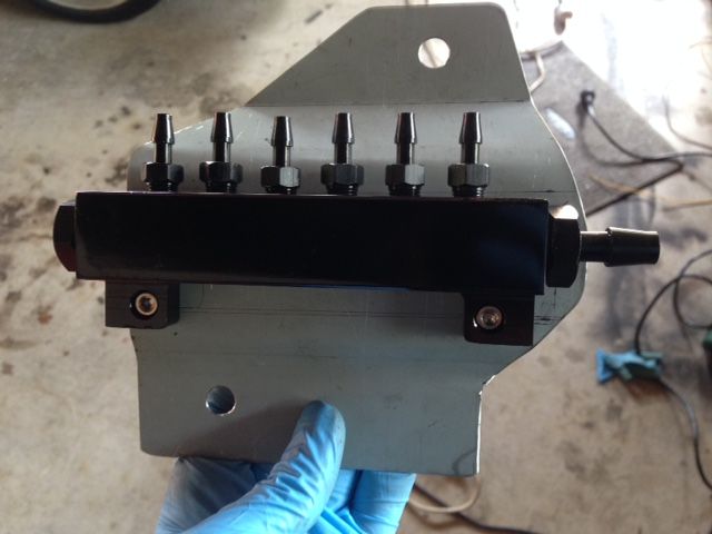
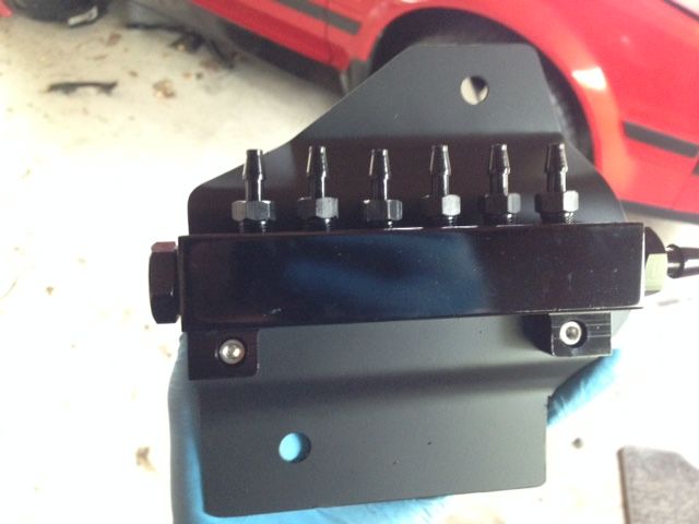
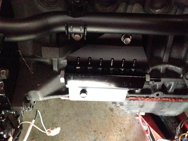
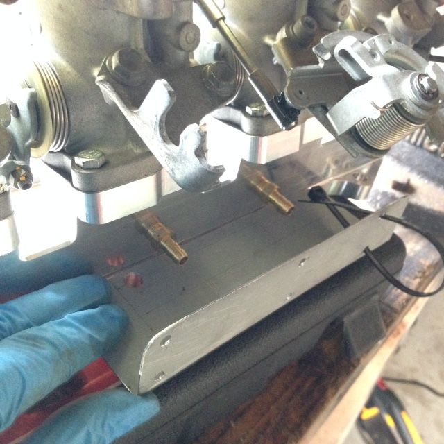
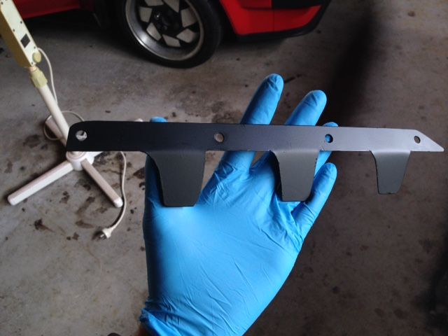
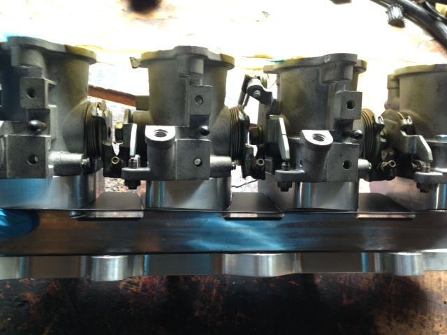
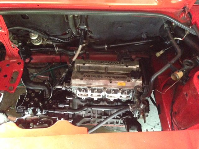
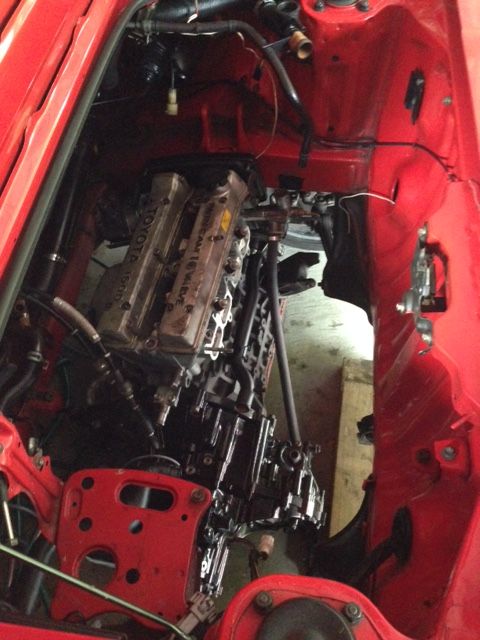
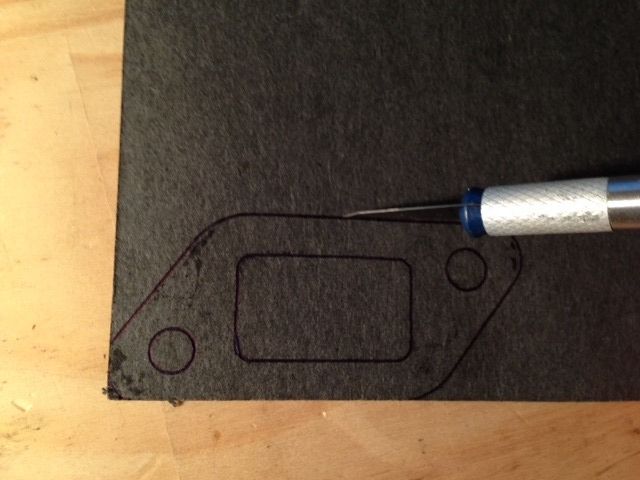
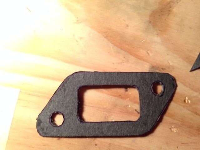
So I had been checking most of the junk yards/parts places but no luck. The closest I got was an automatic AW11 but I needed a manual mount =/I even walked though a mini swamp to get to that AW11: Rather then waiting around for someone to wreck an AW I decided to just buy one from overseas. Of course shipping would take a while but I had to do something.Anyway while waiting for it to arrive I got on with other work which could be done without the mount.Firstly I made a gasket for the intake adapter:After this I started on the wiring. While I am retaining the original wiring harness, I didn't want it to sit on top of the ITB's. I also had to substitute the 16v TPS plug for a silvertop plug.Here is the harness after it was removed from the car:First step was to remove all the old plastic harness protectors and insulation tape:Once all the wires were exposed I could manipulate the wires to make them fit the new layout better. I test fitted the harness to get an idea of how to route the wires:Once I had the layout sorted I used electrical tape to create branches in the wiring harness so that it could be organized better. This allowed me to fine tune the routing/see if it would work:Since I am using the automatic harness I had to modify the reverse light switch wiring. These are the connectors which originally plugged into the autobox:I used some references/pics I found on the internet to help me modify the wiring.Some wires also had to be lengthened:Here's the harness after being completed and re-wrapped and covered with harness protectors:Next I needed to create a bracket to hold the vacuum manifold. I also wanted to hide this out of sight.cardboard template is really useful, this is the finished shape:Transferred to metal and cut out:Mounting holes drilled and in the vice for bending (I don't have a proper bender):With the vac manifold attached to it:Primered and painted:How it looks fitted to the engine:Using a similar method I made a bracket to support the wiring harness:Because the injector wires will be passing very close by the throttle linkages there is a chance the wires could get caught and cause dangerous situations. So I made a piece to prevent this:The wires will pass though the gap between the metal plate and the intake adapter:Anyway by the time I finished all this my transmission mount arrived!I'm sorry to say I didn't really take any pictures mounting the engine or installing the many misc. items (such as water hoses, brackets etc.) I was too busy working and trying to get things done.But anyway here it is installed:Still have a whole lot of small jobs to do but I'm really glad its finally in and mounted.
-
 11
11
-
Oh what, seems I'm alone in enjoying it haha.
I think for an opening episode where they set up the show etc. it was fine. I'm looking forward to future episodes with challenges and that kind of stuff.
I agree with the guest star dying thing, it wasn't that funny, but that seems like just a first episode thing again.
I'm also the same with the supercar reviews and stuff. Even on old Top Gear I always preferred the challenges and overseas adventures.
-
3
-
-
Man, this is amazing to see. Great work!
-
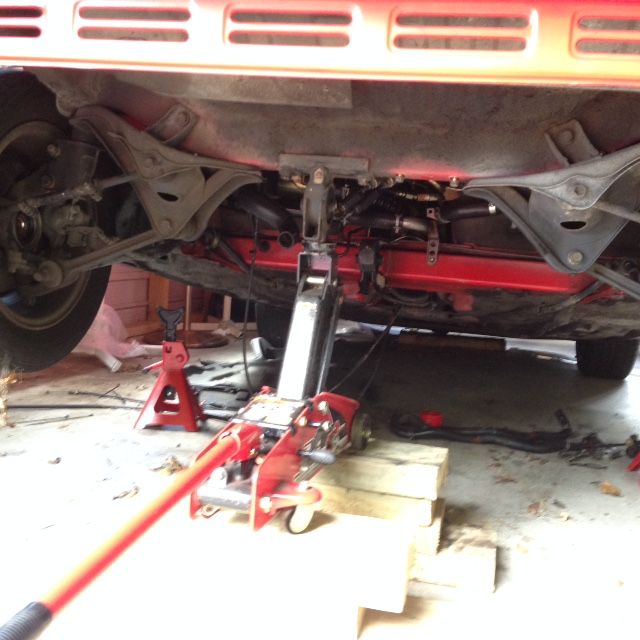
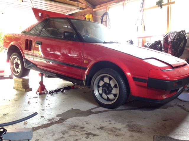
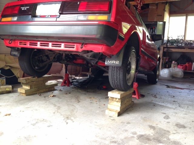
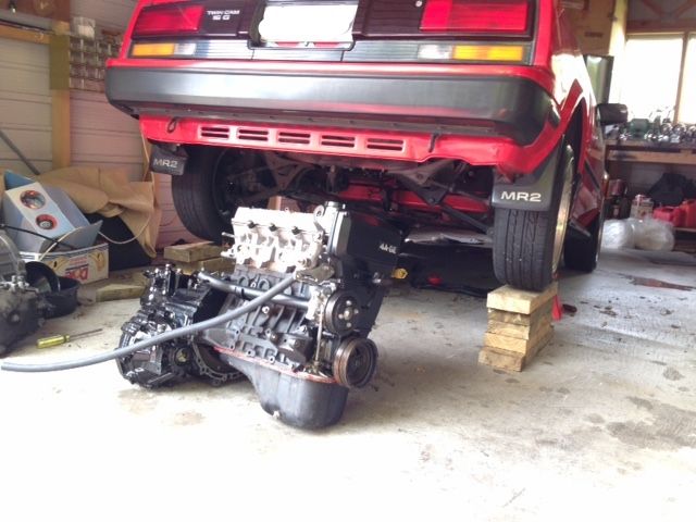
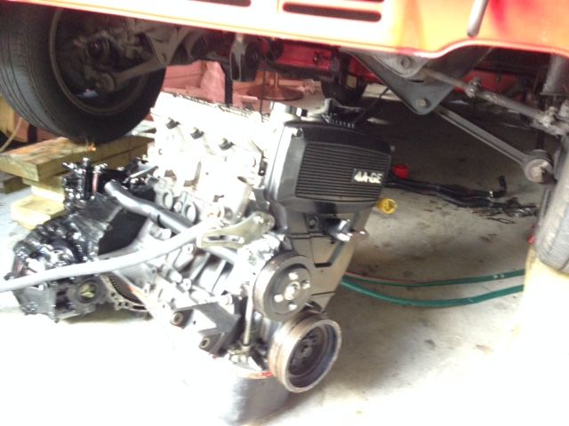
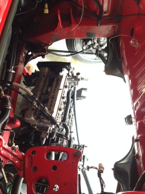
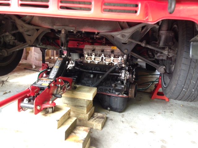
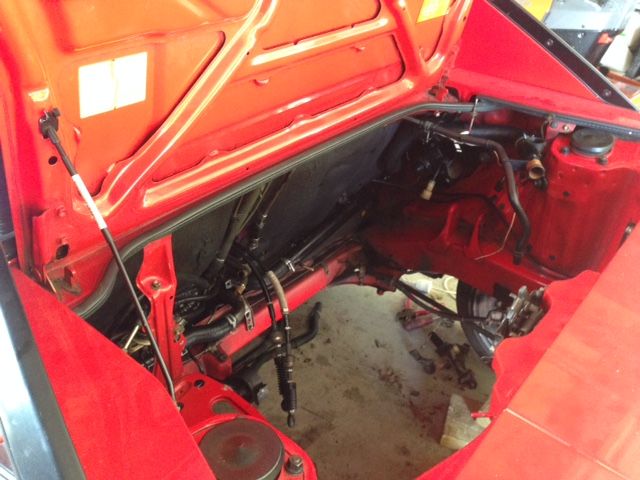
A little more progress.One of the more difficult parts of working on the MR-2 is engine removal and installation, due to the engine being in the middle. Apparently it's possible to fit the engine from the top using a crane, however, its really tight and the chances of scratching or denting something are pretty high.So the only other option is to position the engine from the bottom then lift it up to the mounts using a crane. This is what I did.Jacking the car up. This had to be done in stages because as you can see the rear has to be lifted quite high and I only have basic tools. I had to jack the car up as high as possible, rest it on axle stands, place wood blocks under the jack and repeat.Another angle:Final height required to slide engine in:Engine ready to go in:Uhh.. yeah this was pretty ghetto, I used an old garden hose as a rope to pull the engine into position haha. I couldn't find any real rope and don't have a sliding trolley.For anyone trying this method: You must position the engine as far forward as possible (closest to firewall as possible), this is because when you lower the car it slowly rolls forward (opposite to when you were jacking it up). If you place the engine in the middle of the engine bay, the car will hit the engine before it is fully lowered. I learnt this when I was removing the engine. No issues this time around:Time to lower:Safely back on the ground:Unfortunately I now have to wait till I can find a rear transmission mount (one under the battery tray). I didn't realize the auto one was different to the manual : / Its pretty annoying since I wanted to get stuff mounted.Anyway that's it for now.
-
4
-
-
Alright I'm back. I haven't worked on the car for a few months since uni got crazy busy (was my final year).
Anyway here's some recent progress. Note: I got out of the habit of taking a lot of pics etc. so if you feel like some are missing or things aren't shown clearly, that's why.
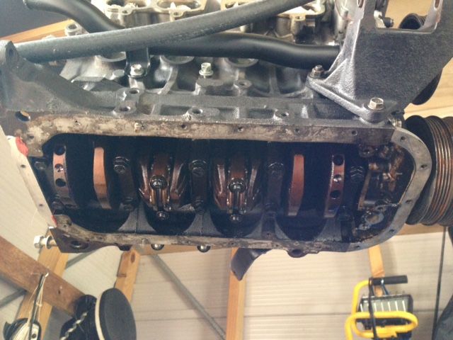
So, I the first thing I did was install the oil sump. This involved installing the windage tray, oil pickup and sump.
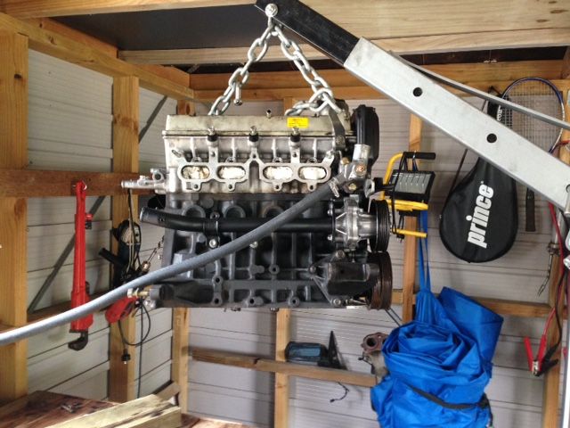
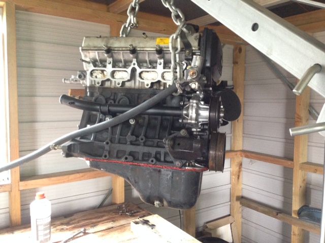
Engine up in the air:
Cleaning up all the old sealant:
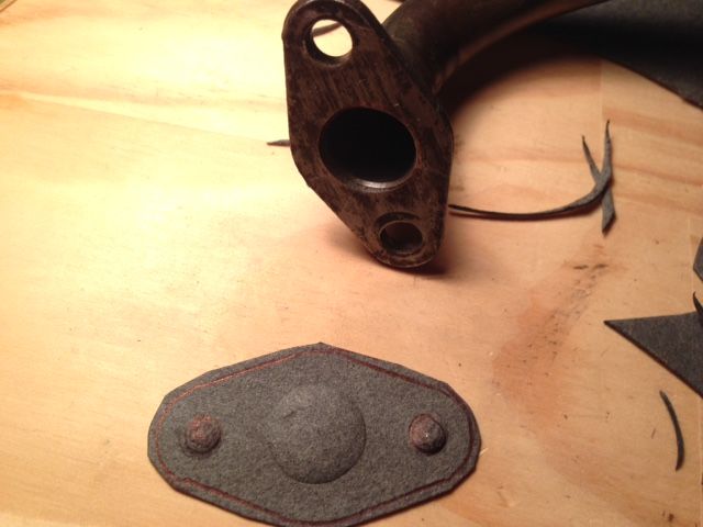
Making the oil pickup gasket:
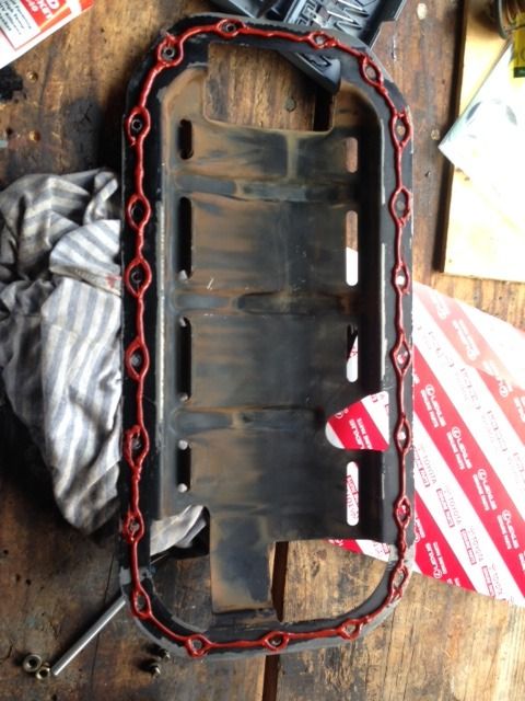
RTV applied to windage tray
At this point I installed the windage tray and bolted it into place using the oil sump bolts. I let it sit for about 10 minutes so that it would get tacky and hold onto the windage tray while I installed the oil sump. The bolts for the oil sump and windage tray are the same.
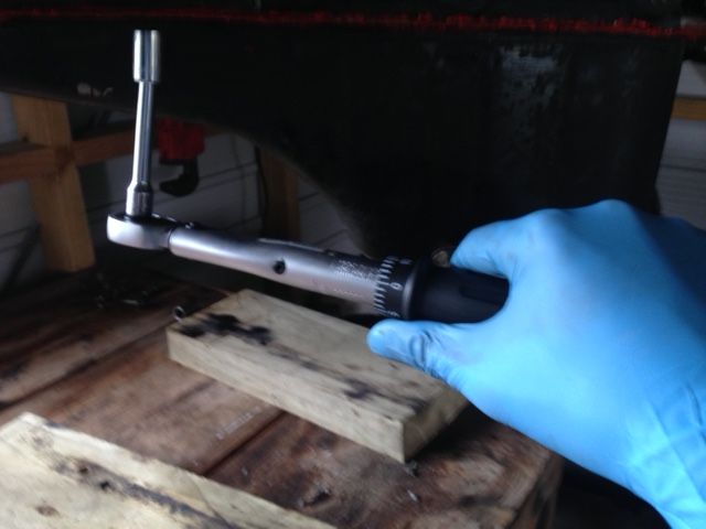
I also installed the oil pickup tube at this time and torqued it to spec.
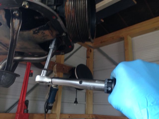
Oil pan being torqued:
Done:
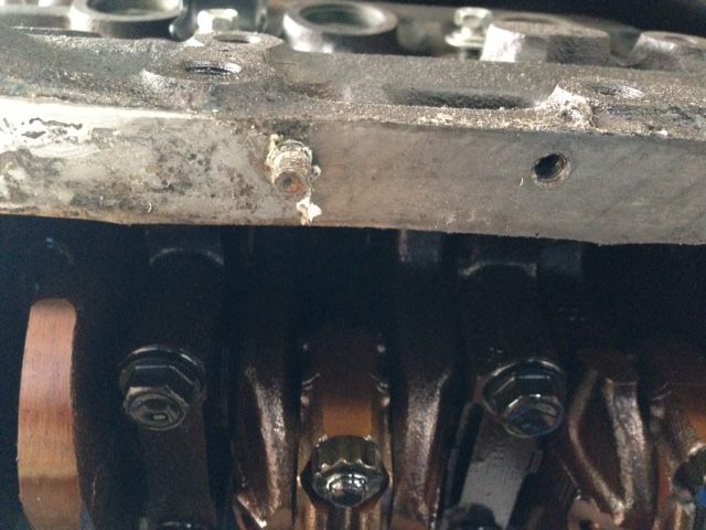
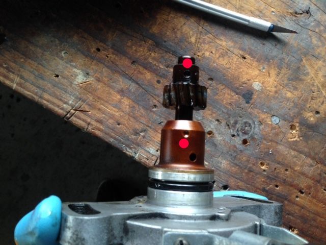
I also remembered that I had not clocked the distributor and installed it properly. So that was the next task. Engine was turned to TDC position. The distributor shaft was clocked as shown in the pic below: (Note the two dimples highlighted by the red dots).
The distributor was then installed, it went in without trouble. Once the engine is in and running (I really hope it runs), then I'll time it using a strobe light timer.
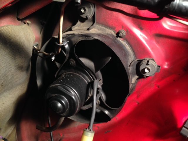
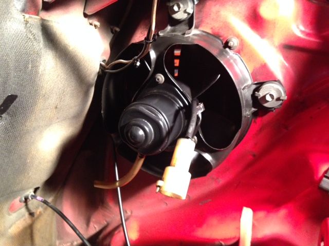
Once this was done I was just having a look at the engine bay for no real reason. I noticed that the engine bay air fan was pretty dirty, as well as the coolant hoses/oil cooler. No better time to clean it than now.
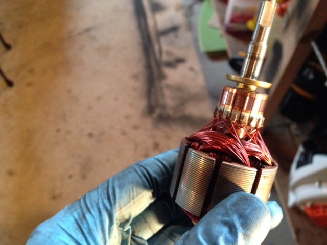
This is the engine bay air fan. It automatically switches on only when the air temperature in the bay gets above a certain level:
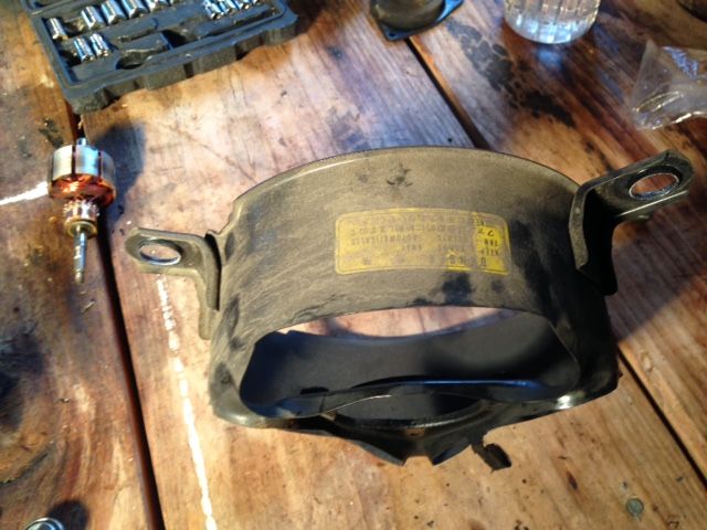
Disassembly:
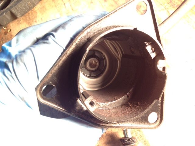
Notice the dust or whatever, inside the stator (Yes the fan was working):
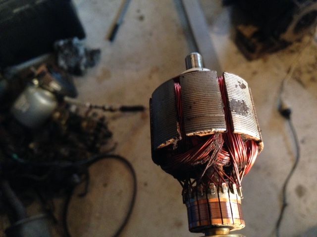
Rotor also dirty:
Cleaned up rotor:
Stator cleaned up:
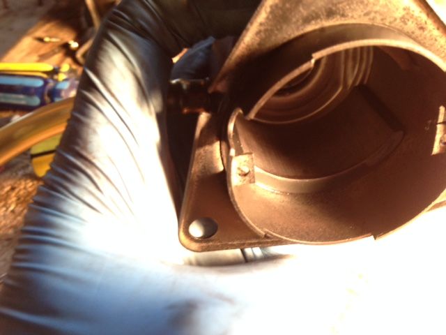
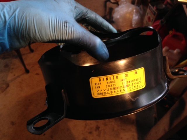
Cleaned up housing:
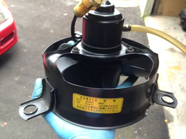
Put back together:
Re-installed:
This project has started to really take much longer than anticipated, mostly due to uni being so busy this year. Anyway I need to get the car back together so that I can enjoy it during summer. If I get it back together and it doesn't run...
So I decided it was time to get the transmission and engine mounted. Before I could do this the clutch had to be installed. You might remember seeing my brand new Exedy clutch kit in one of the above posts. It had been sitting in my room for the last few months. When I went to installed it the clutch alignment tool wouldn't fit into the clutch disc it was way too large. Kind of annoying since I had to wait another day for the shop to re-order the correct tool. But I don't think it was their fault (supplier sent wrong one most likely). Either way I'm glad they sorted it out so quickly and easily.
Once the new tool arrived I got to work.
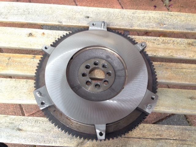
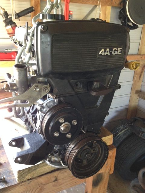
Here is the flywheel after grinding (As you can see its from a blacktop 4AGE so its lighter than the original but still factory like usability):
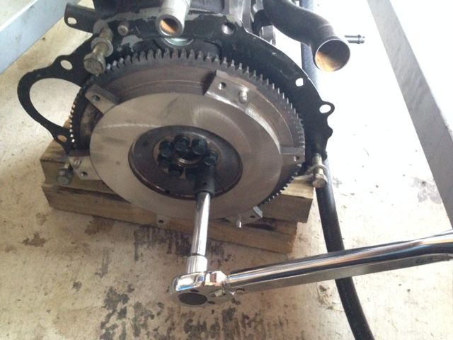
Bolting it to engine and torquing (Note: All new flywheel bolts from Toyota, were pretty expensive but its highly recommended to use new bolts for this):
At this point I thoroughly cleaned the flywheel and pressure plate mating surfaces with wax and grease remover. I did this until no residue appeared on the cloth.
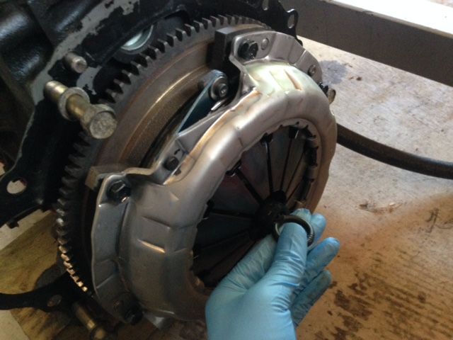
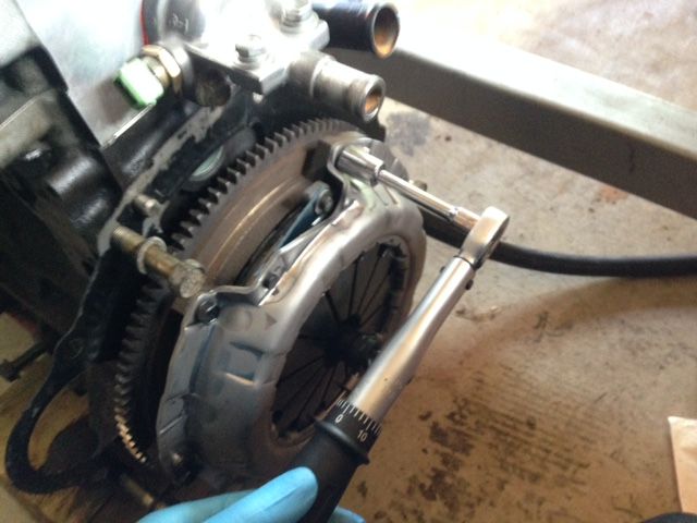
I then fit the pressure plate over the clutch and used the new pressure plate bolts to lightly hold everything in position. This allowed me to make sure the clutch was centered:
After confirming the clutch was centered I started to tighten each of the six pressure plate bolts as evenly as possible to avoid warping of the pressure plate. After this the bolts were torqued to spec:
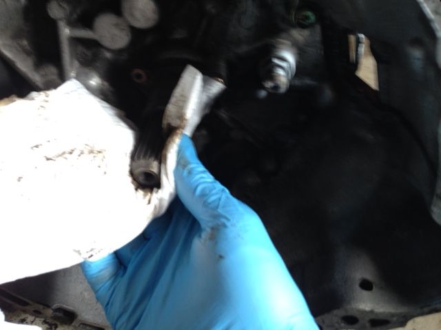
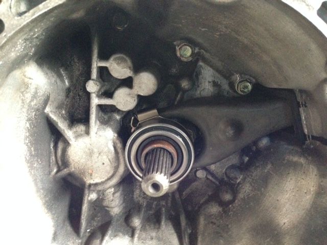
Cleaning up the transmission input shaft and clutch fork pivot ball:
I then lightly greased the input shaft splines and the pivot ball. Its important to only lightly grease these; excess grease can fling off onto the clutch disc and cause slipping (or so I'm told).
Clutch fork and release bearing installed:
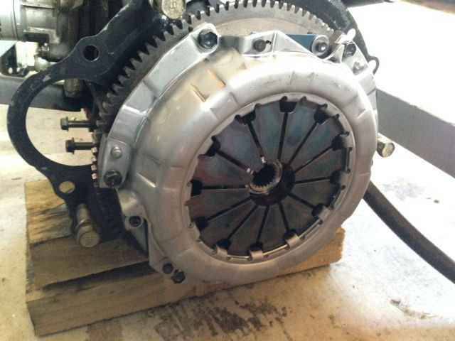
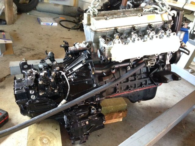
Finally mounting the transmission. I know it looks like its hanging from the input shaft but don't worry I wouldn't do that. It's resting on the diff part of the transmission which is hard to see from the pic:
Done:
I also cleaned up the engine bay a bit more:
That's it for now, it feels nice to be working on the car again. Sorry for the shitty pics though, lol.
-
5
-
-
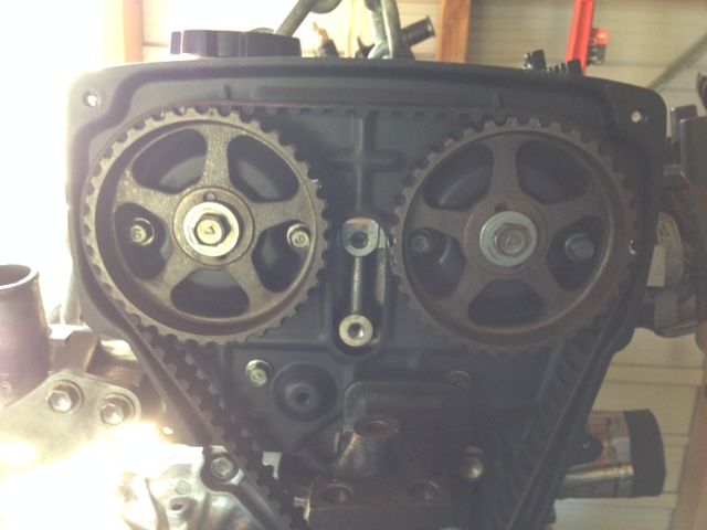
Installed the timing belt.
I know the timing marks seem off in this picture, but I checked and its just parallax error (can't get camera to see both cam sprockets dead straight).
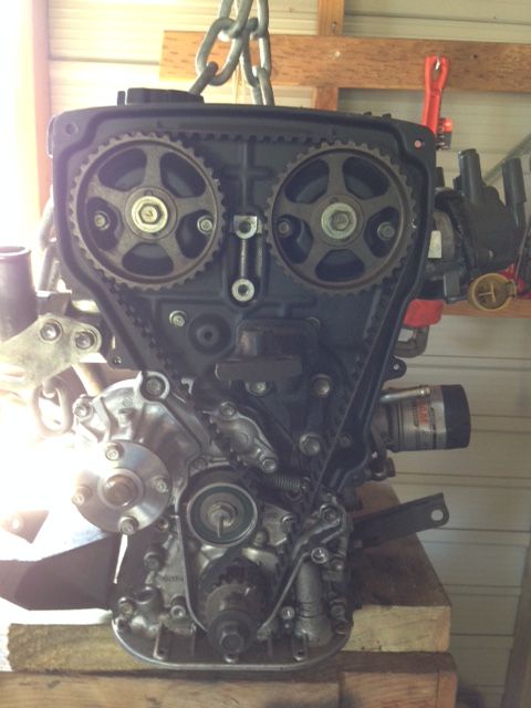
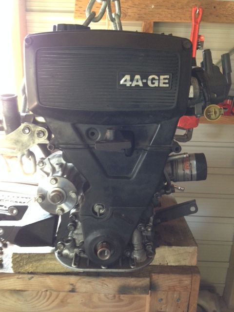
Covers installed:
Little bit of copper anti seize on the crank pulley:
Pulleys installed, I didn't bother re-painting them because later on I will replace them with aftermarket ones. The car never had an AC from factory, yet the crank pulley is double row, I'll probably go with T3 pulleys when the time comes.
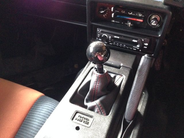
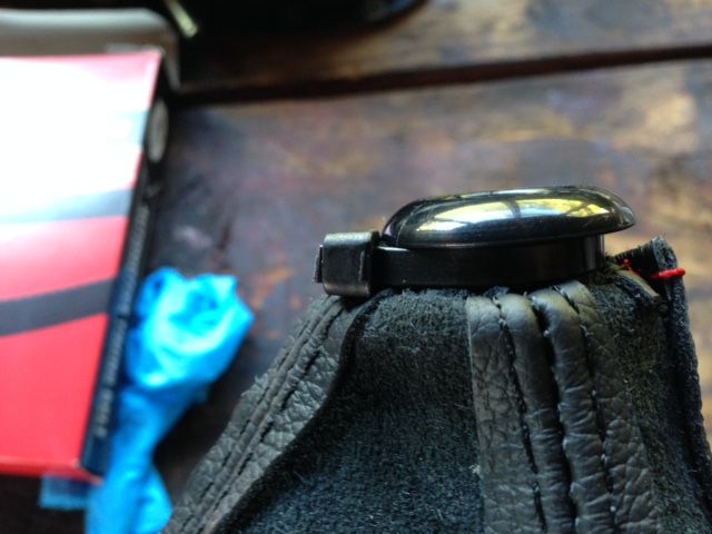
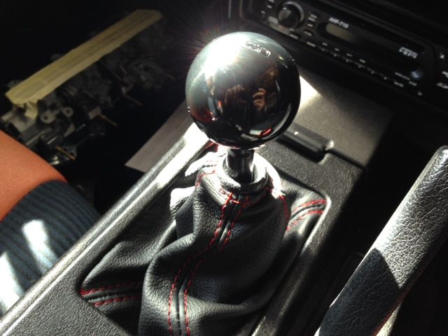
One thing that annoyed me every time I looked at the interior was the shift boot I bought. It didn't have any retainer on the top and looked really unfinished.
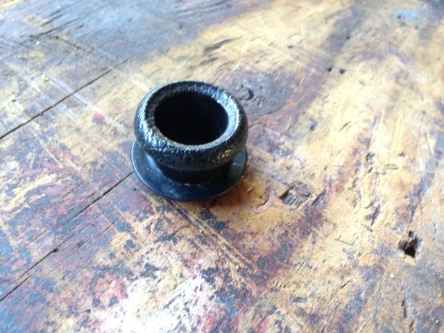
So I noticed that a lot of old Honda's have a nice retainer and picked one up from the junk yard:
Zip tied onto boot:
Better:
That's it for now.
I've ordered some new flywheel bolts from Toyota, but they will take three weeks to arrive from Japan.
-
3
-
-
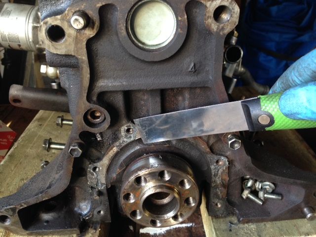
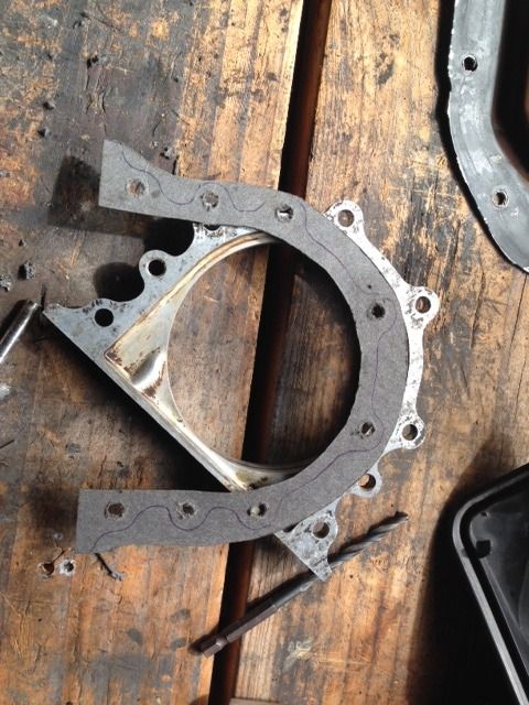
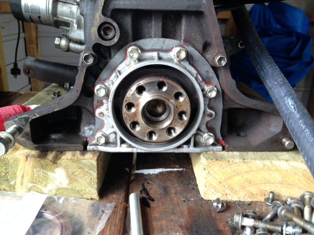
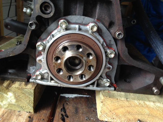
Had some time to install the rear main seal:
scraping off the old gasket:
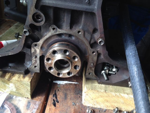
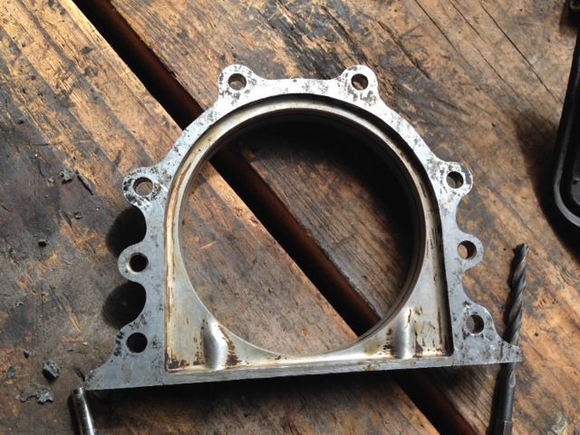
Cleaning up seal retainer:
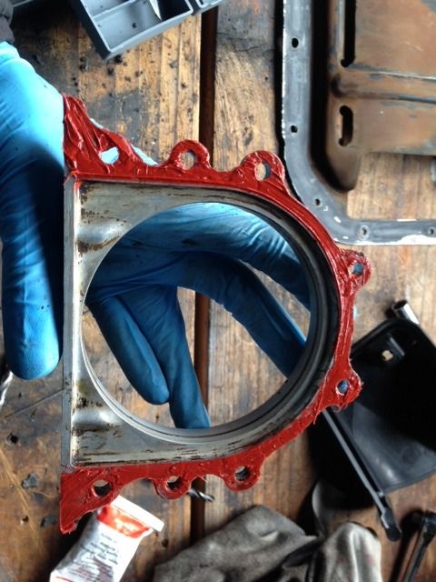
Once again I used some gasket paper to make my own gasket:
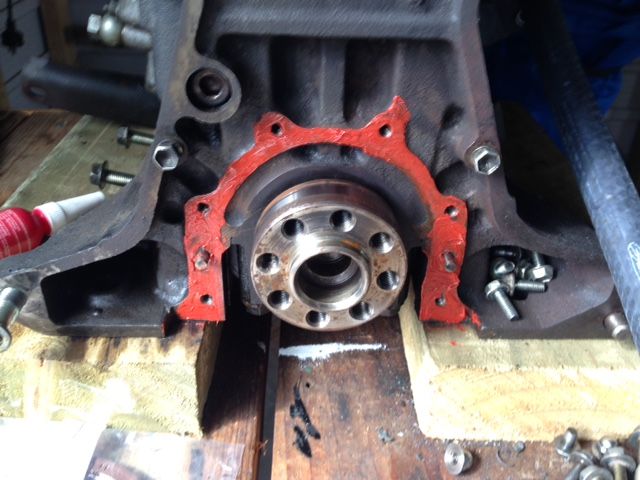
RTV for a better seal:
Don't worry I did wipe off that excess RTV in the corner (always seems like I go insane with RTV in pictures, not sure if actually insane):
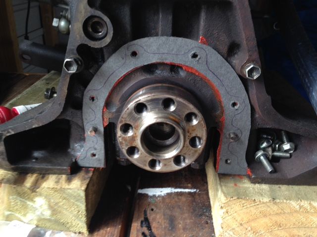
Finally the new Toyota seal is in:
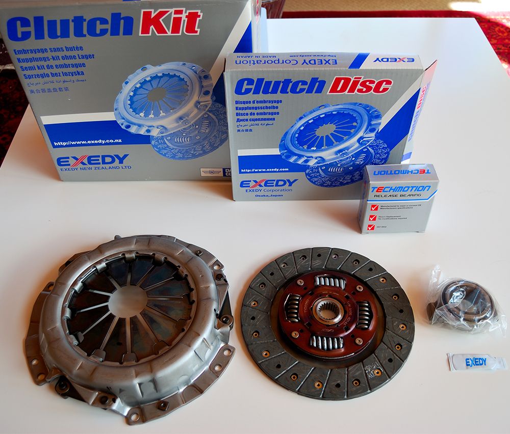
Have been doing some shopping too, here is the Exedy OEM spec clutch I just bought. I wanted to go with OEM spec because I'm not going to be adding much extra power to the engine, its not the aim for this project. Also OEM clutch has a nice easy feel.
By the way, this is the kit for an AE111 4AGE 20V (Since I'm using a black top flywheel), which.. now that I think about it, has more power and torque than my engine will. No problems.
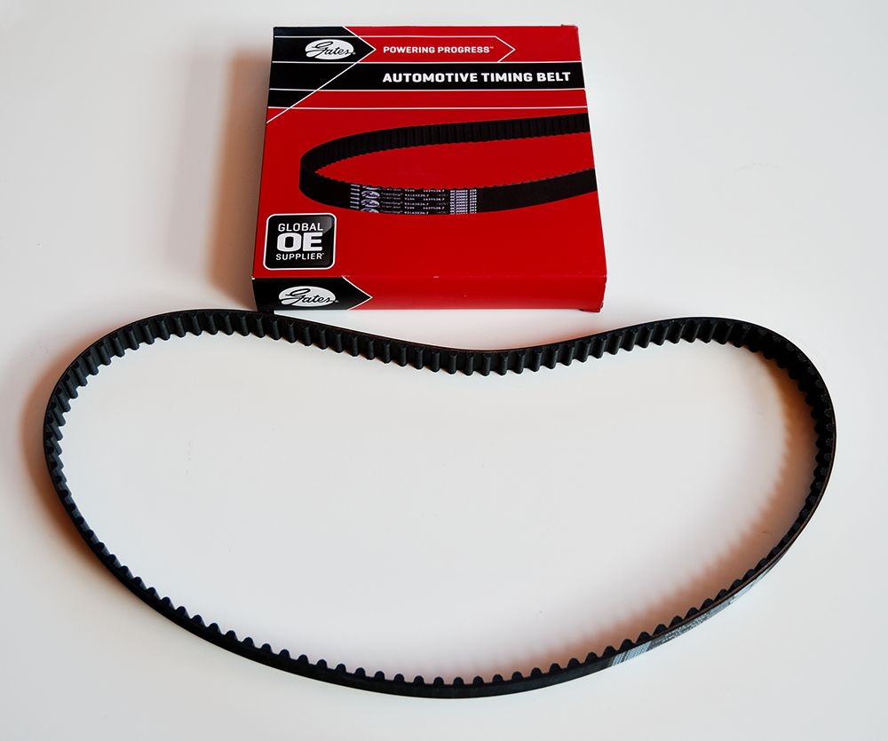
New timing belt:
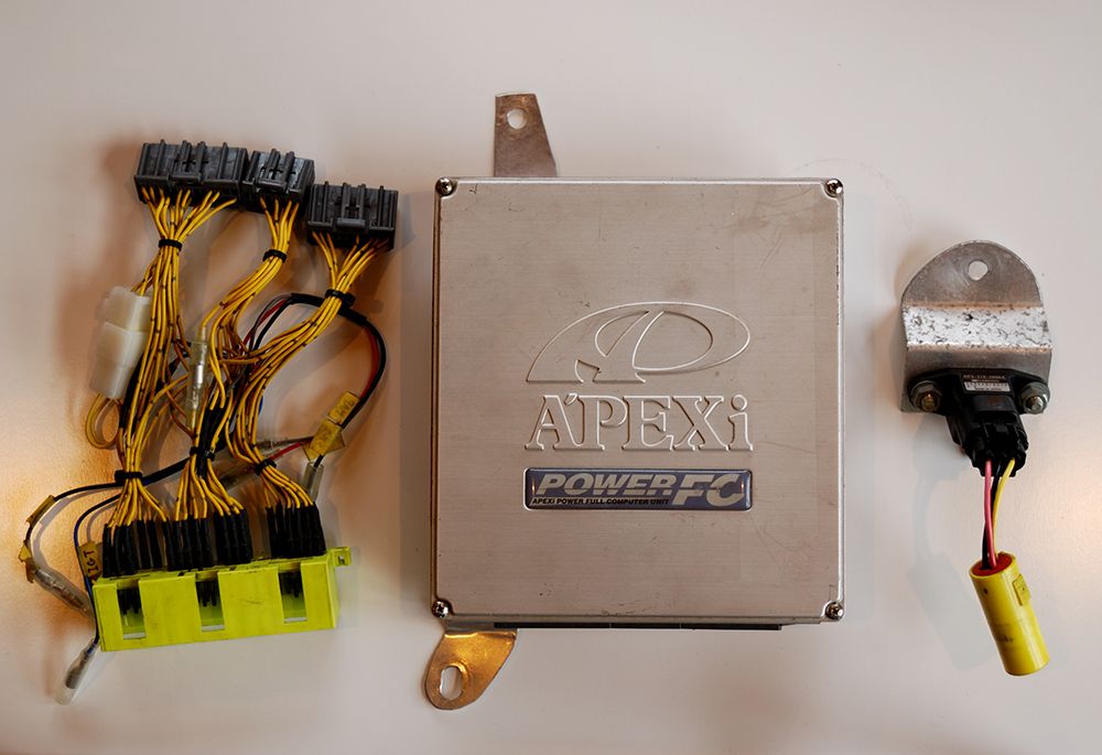
And something a bit more fun. An Apexi Power FC made to be plug and play for the 4AGE 16V bigport (Specifically for the AE86 but should be workable with the AW11).
Apparently they don't make this for the 4AGE any more, I just hope it'll work and save me some money and time buying a brand new ECU and wiring it in.
My actual plan is to try the stock ECU to see how it copes with the ITBs (JDM map ecu), according to a few internet people it can cope relatively well as long as you use a vacuum manifold (of course). Who knows, we will see.
Even if it does run I will eventually switch to the Power FC and get it tuned.
That's it for now.
-
7
-
-
You could also go on a raid to pick-a-part and get some banjo bolts / fittings with barbs.
Lots of Toyota's have these for the brake booster vacuum lines, but you may need to drill and tap the adaptor to suit.
Also, replacement banjo/barbs for the likes of Tial wastegates, I'm sure some more 'generic' ones exist from Autoquip or GSS?
you can see 2 of them here:
For a second I thought you were going to suggest turbo charging it lol.
I never knew banjo type fittings were also used for vacuum, that could be a nice solution.
Ideally I would like to keep the adapter as untouched as possible, but since its probably unlikely I'll find any banjo fitting with 1/8 NPT thread, I might not have much choice.
Anyway thanks for the suggestion. Will see which way I go.
-
Looking very nice.
You should be able to get an angled vacuum fitting, which might help
Yes I did actually buy one of those but when I went to put it in I found that the tip would touch the front flange of the ITB adapter (Because you have to spin it around to screw it in).
The one I tried was angled more though so I'll try one with less of an angle.
Just have to find one like that with NPT thread.
Anyway thanks for the suggestion, if it works it'll look much nicer than the heater hose.
-
Another small update:
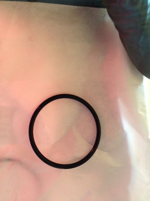
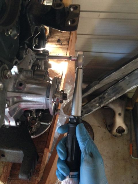
Installing the water pump, with new O-rings of course:
Torqued to spec give by the BGB:
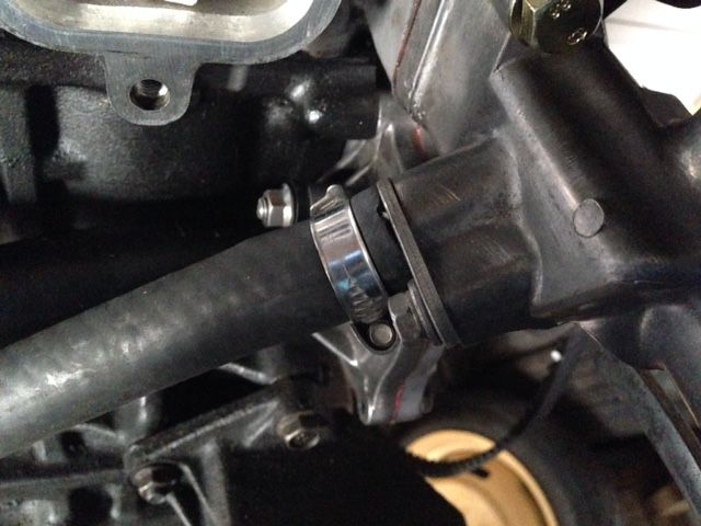
Water pump inlet O-ring:
Inlet pipe:
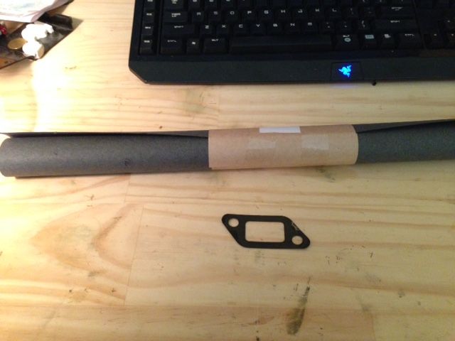
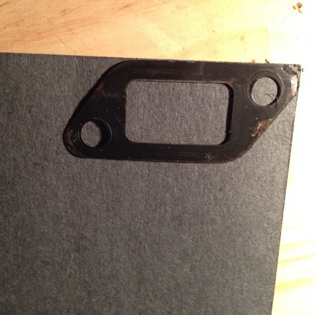
There are quite a few misc. gaskets which needed to be replaced. I thought I would try to make my own using gasket paper which is supposedly designed for this purpose (from BNT).
Another one for the heater outlet:
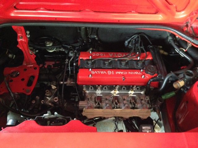
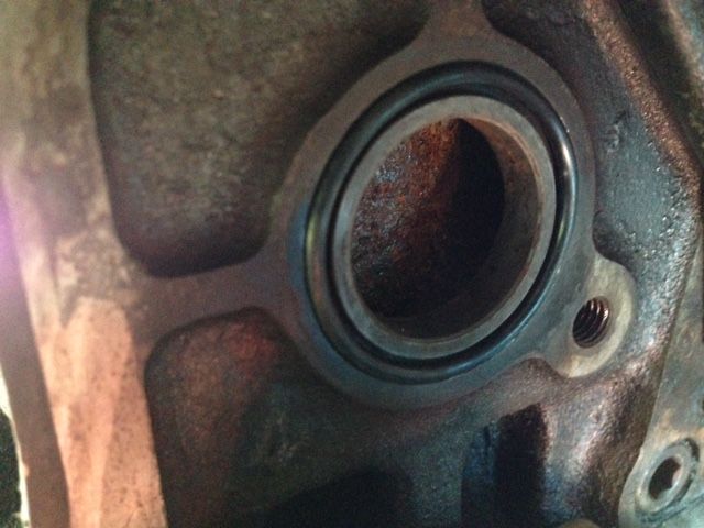
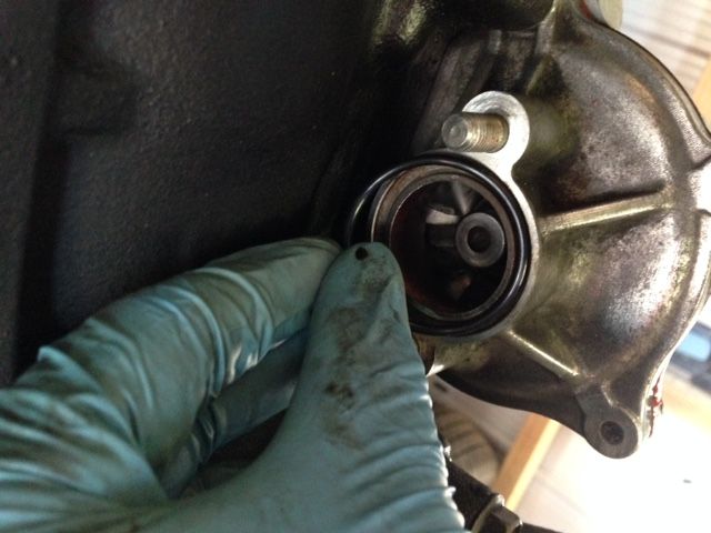
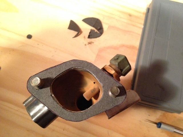
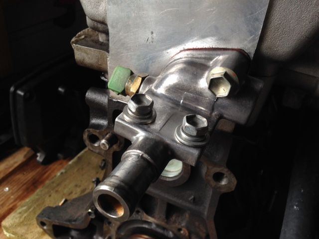
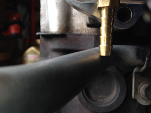
Now when test fitting the bypass pipe with the ITB's there was a little problem:
As you can see circled in red, the water fitting and ITB adapter are very close and actually touching. If I recall correctly it wasn't allowing the adapter to mount up perfect to the head either:
There were also some issues of interference with the vacuum barbs, the gap between the bottom of adapter and top of pipe is less than it seems:
This one was minor:
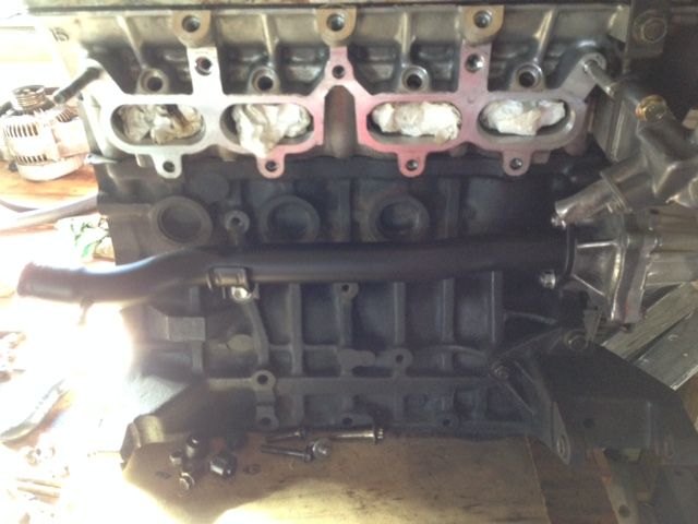
So firstly I filed down the ITB adapter so that it could mount flush with the head and have a little clearance from the water fitting. It seems like not much, but this was enough:
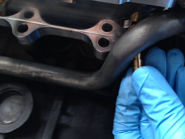
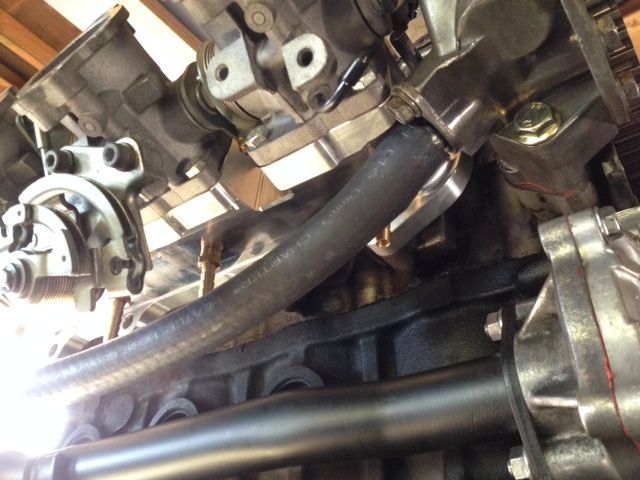
Next I tried to bend the water pipe so that it wouldn't interfere with the vacuum barbs. It was easy to bend the last part to avoid the barb on cyl 4, but the other one was more difficult.
I found it difficult to bend it and keep the mounting holes in the right position, it also needed quite a bit of force since it was already bent into an S shape on that side so I couldn't do it while bolted into the engine.
So although I don't like it, this is what I ended up doing, cut off the pipe leaving a good length to attach some heater hose to.
I'm still not that pleased with it, will of course have to find a way to secure it and stop it from flying around.
I may find another pipe and try again, however, when I bent the pipe enough it had some stress marks on it seemed like it wouldn't be a good idea to use it.
The bend required looks a lot less in the pics. I tried using a shorter vacuum barb but there is not enough length with the pipe there directly under it.
If anyone has a better solution feel free to share it. I'm not happy with this solution but I don't have any experience or skill fabricating new stuff.
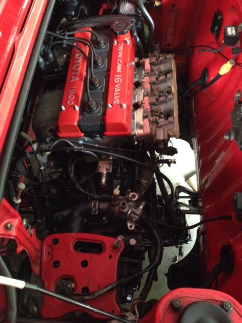
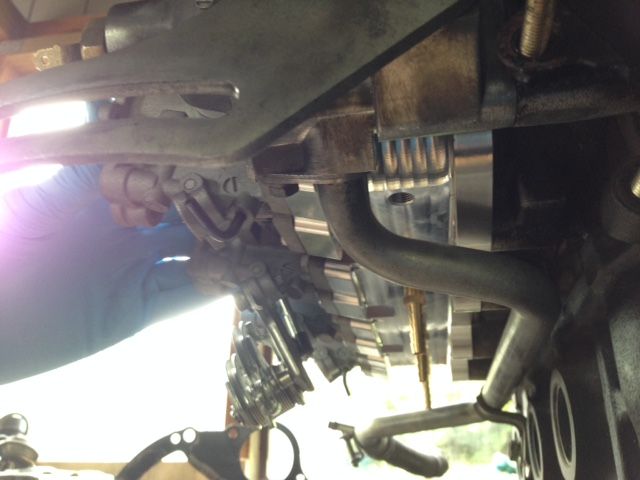
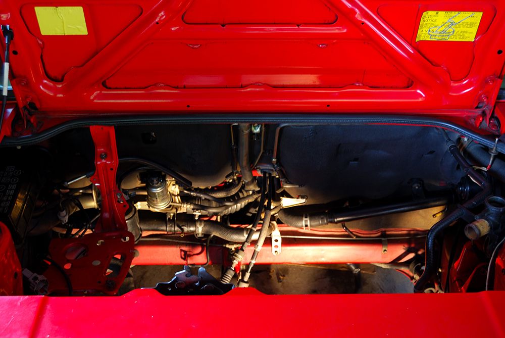
Anyway engine bay has been cleaned and is almost ready:
That's about it for the progress.
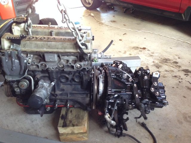
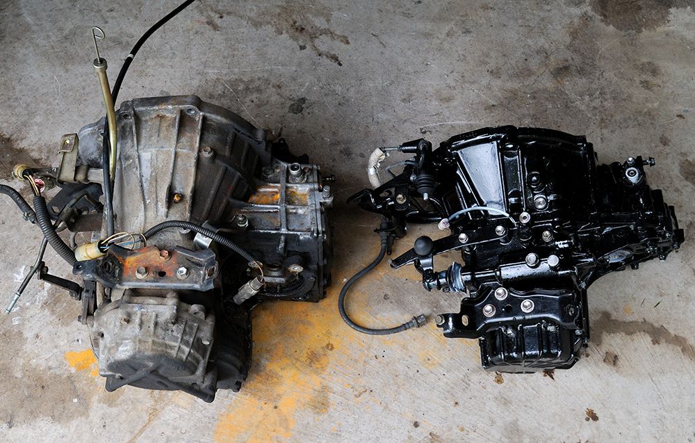
I also spent some time cleaning up the garage which seems to get messy and chaotic too often. I happened to take a pic comparing the relative sizes of the auto vs. manual trans:
Auto on left: Manual one is not too difficult to pick up for me (I got stick arms), but the auto... no way.
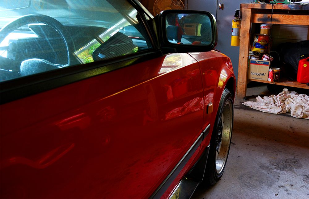
Also here is a random shot/teaser of how the wheels look which I mentioned before. The tires are one aspect ratio too small which is creating more wheel gap, its just what the wheels came with though:
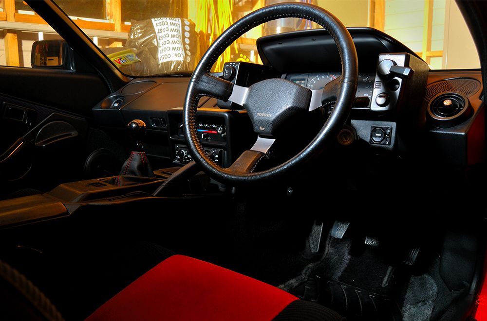
Interior is also back together after all the covers were removed from shifter/clutch pedal install:
-
6
-
-
Man your starlet and build thread are amazing. Can't believe you just made your own rotors, that shit is crazy.
Engine bay is looking very nice too.
-
1
-
-
With the accl pedal, for me it was a little to far away from the brake pedal to heal toe well I and I would sometime miss it and end up with a little compression lock here and there.
Hey, thanks for that tip.
I've never actually driven a manual AW so will have to see how bad it is for me. My shoe size is 11 US so it might be alright; although I like to heal and toe more with the side of my shoe than the actual heal.
Will see how it goes.
Thanks for the notice, if I need some parts I'll check with you.
-
As mentioned in my last post, I don't have much time to work on the car anymore; so basically I'm trying to say my updates won't be as large as they were.
Probably a good thing looking back at the length of my first page.
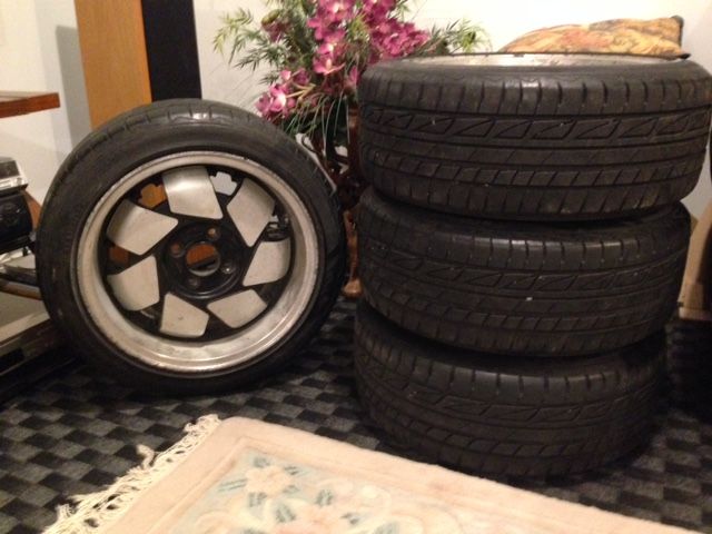
Before the engine blew I had taken the car for a WOF, it was all fine except for needing new tires. Rather then buy new tires I thought I'd try to find some nice looking aftermarket wheels with tires.
So just yesterday I picked up a set of ATS Type 5's off Dave from oldschool. They do need a bit of restoring but I already knew this since Dave had told me and sent accurate pics.
Thank you Dave.
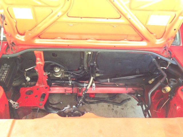
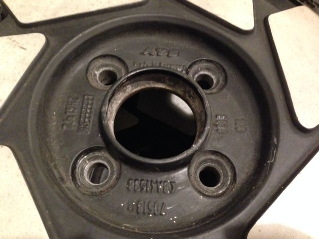
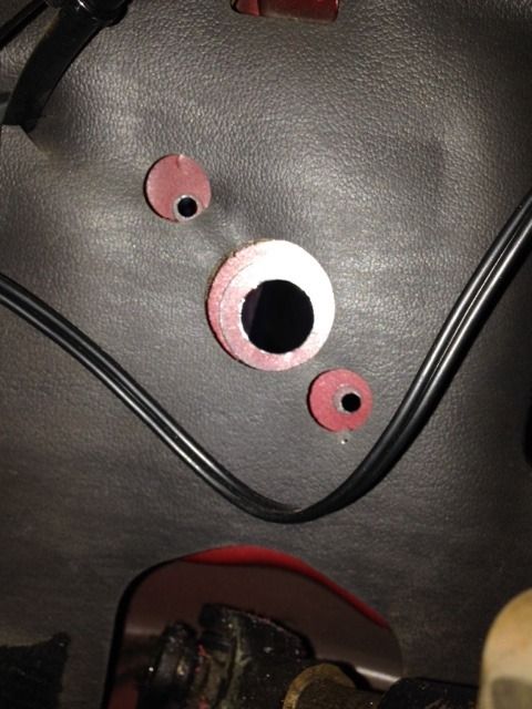
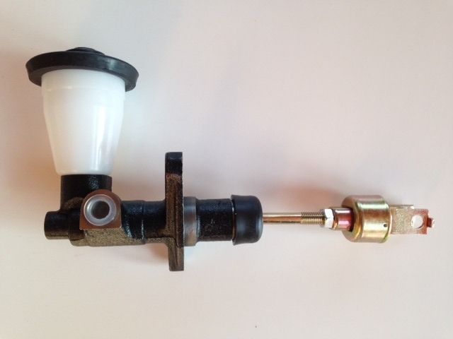
I also finally bought a new clutch master cylinder so was able to install the third pedal. Finally the manual conversion is complete (still transmission/engine needs to go in but chassis conversion is done).
In order to install the clutch master/clutch pedal, some holes needed to be drilled. Thankfully Toyota had already marked out the position for these, I can't imagine how hard it would have been to accurately mark them out in such a location (without removing dash).
In this pic I have started the holes, in order to get the center one to the right size I had to hand file using a half circle file (no large enough drill bit).
New master:
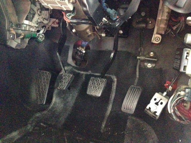
Finally three pedals:
I forgot to take pictures but I did use some rust prevention spray on the bare metal exposed by drilling the holes for the clutch.
-
4
-
-
-
-
-
-
-
-
Sorry but the next few posts are just to reach 20 posts and get this thread onto page two, because this first page is too damn long.
Sorry to admins for posting more than 5 pics in a post.
-
Unfortunately Bill (previous owner) passed away a few months ago but I am sure he would be happy that you are looking after the car. He had an amazing car collection that I was fortunate enough to explore a couple of years ago. There was a wide variety of makes and models represented including some real flash stuff (e-type Jags etc). I remember that your car caught my eye because it was in such exceptional condition for its age. I don't think he used the car very much while he owned it but I guess that happens when you have a fairly large collection. You have a very special little car there and it is certainly worth putting the time and effort into the project. I hope we have an opportunity to catch up at a Auckland event sometime as I would be very keen to see what you have done with the car.
Ah man, that's really sad to hear. Unfortunately I never got to meet him in person because about 1-2 days before I went to pickup the car he had some health issues which meant he couldn't leave the house. He was kind enough to organize two of his friends to meet me instead, I didn't even know about all this till the night before which is when he called me.
His friend did email me some pics of Bill and a few of his cars from the collection, including one very nice old mini (green I think); once I got back to Auckland.
Your right, Bill did mention that he hardly used the MR-2.
I'm trying to get the project done, have too many other commitments at the moment, but it will get done. Luckily I have a full time garage space available so the car is always stored inside.
Sure It'd be cool to meet up once its done. I don't really have any crazy modifications planned which your probably glad to hear. The most major mod would be the ITB set up.
Thanks for sharing that experience though, cool that someone on these forums knew him and his collection.
RIP Bill.
-
Yeah that's right. I think I might have mentioned it in my build thread. The previous owner was an older car collector, was very nice and funny.
Unfortunately I think his mechanic did not bleed the coolant system properly as the car started to overheat on the drive back to Auckland. I'm assuming this because it had really fresh green looking coolant and after I bled the air on the side of the road it was fine.. for the rest of the trip.
Anyway I don't really mind, its a super clean and straight car which I'm happy to own and work on.
Maybe I'll send him some pics once I finish the project.
-
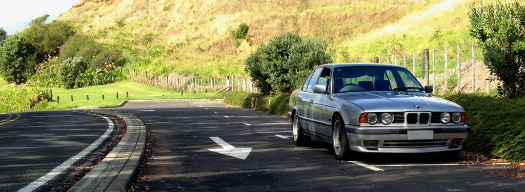
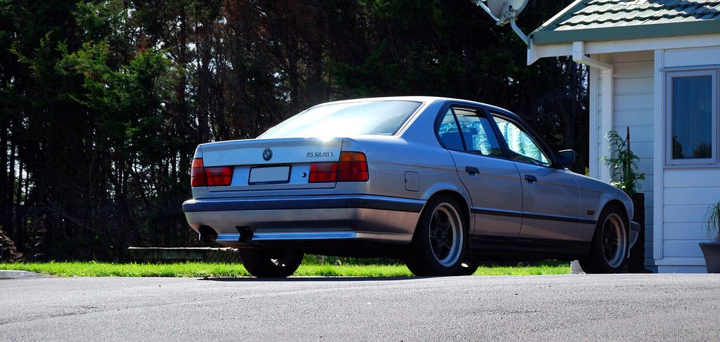
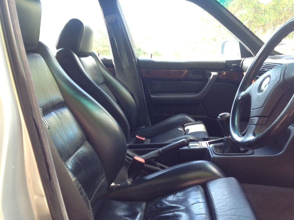
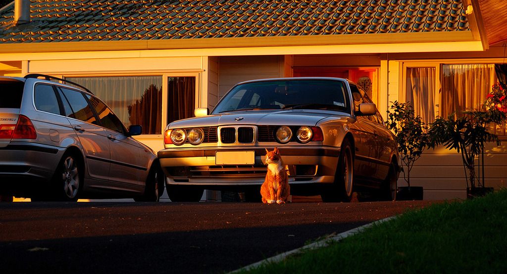
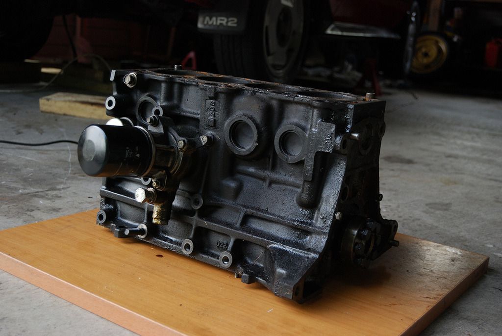
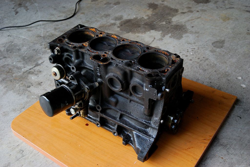
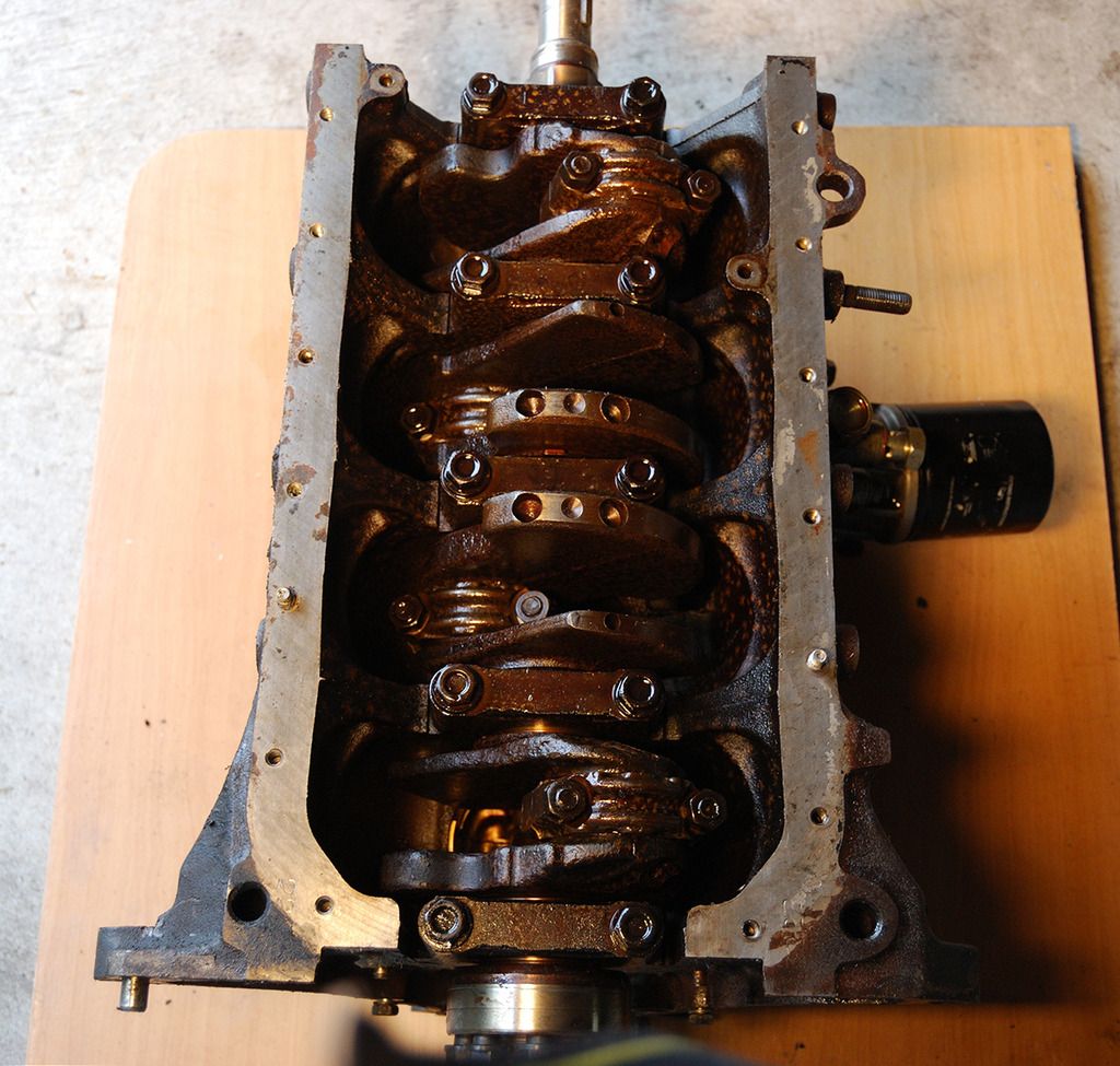
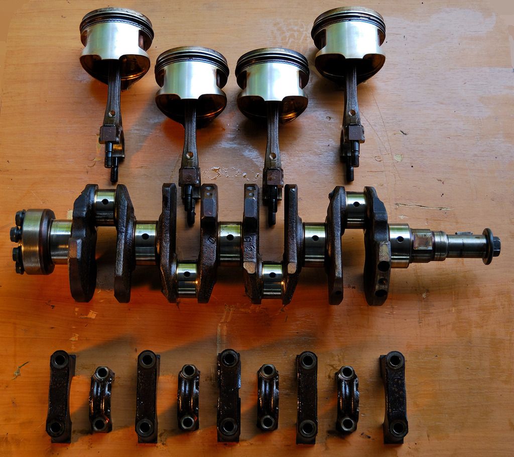
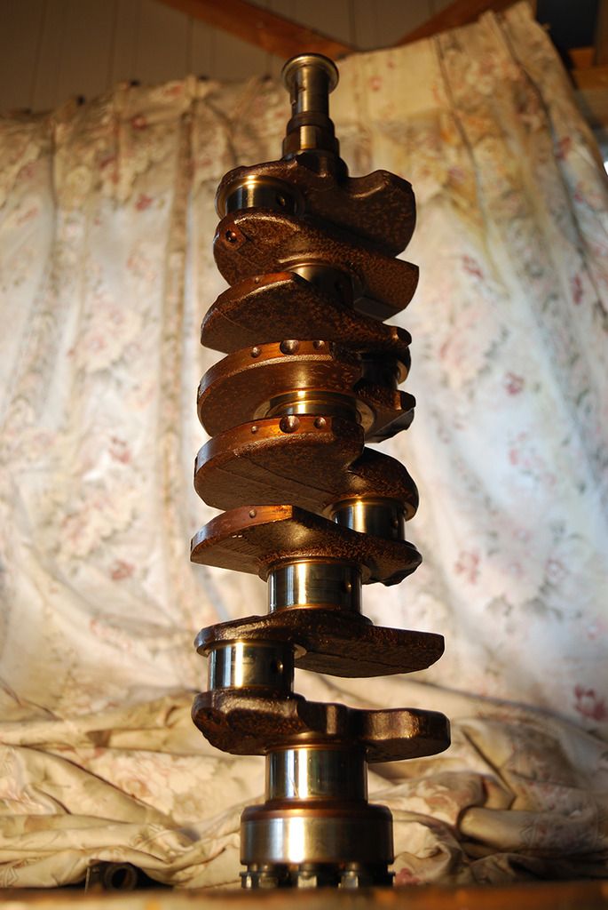
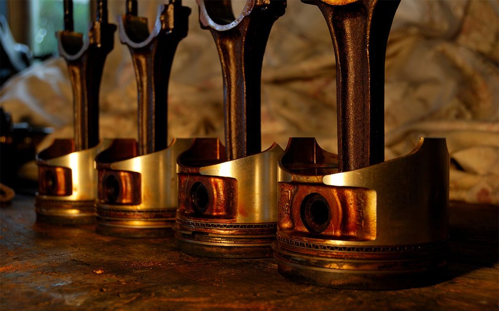
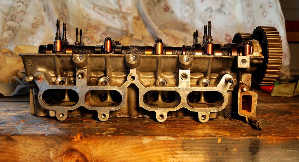
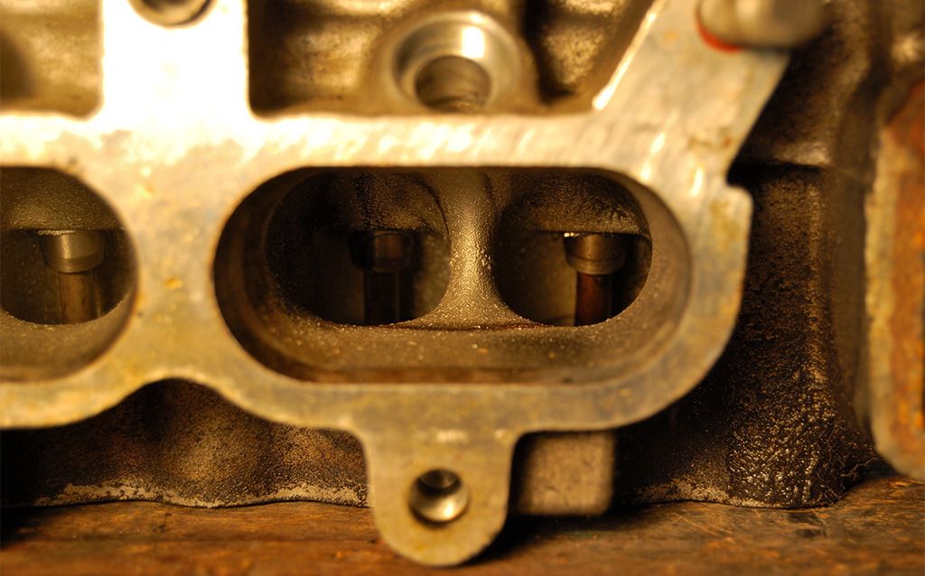
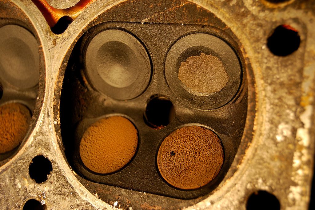
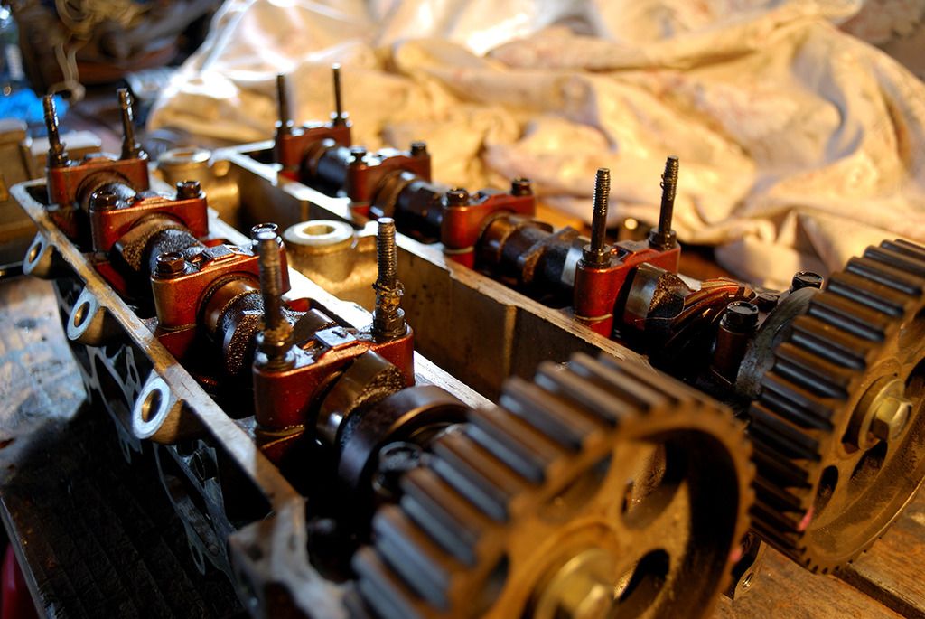
Due to a lot of other commitments and admittedly a lack of motivation in these winter months, I have not made much progress on the MR-2The lack of MR-2 related updates does allow me to mention a few things I've been doing on the side (which are still indirectly related to the project).First off I sold my M52b28 swapped E34. This was my first true project car in the sense that I did the engine swap myself and upgraded many parts. I was double minded about selling it, but at least I should have enough $$ to be able to complete the MR-2 project without being held up for monetary reasons now.Here are some pics of it:Anyway its gone to a new home now.I also took some time to further disassemble the old 4AGE from the MR-2 (overheated engine). I took some photos during the process.The surface rust spots are caused by water in the oil (due to head gasket failure):Well that's it for this update.By the way anyone know whats up with this page length, I thought it would have gone onto page two or even three by now. Getting seriously long..


The Night Rider's 1986 Toyota MR-2 AW11
in Projects and Build Ups
Posted