

legendlives
-
Posts
379 -
Joined
-
Last visited
Posts posted by legendlives
-
-
- Popular Post
- Popular Post
That went well!

-
 12
12
-
Preview vid from the CRC Speedshow.
My little beut is at about 1:15 on:
-
6
-
-
The car is at the CRC Speedshow this weekend.
Hall 1
I'd appreciate your votes!
-
1
-
-
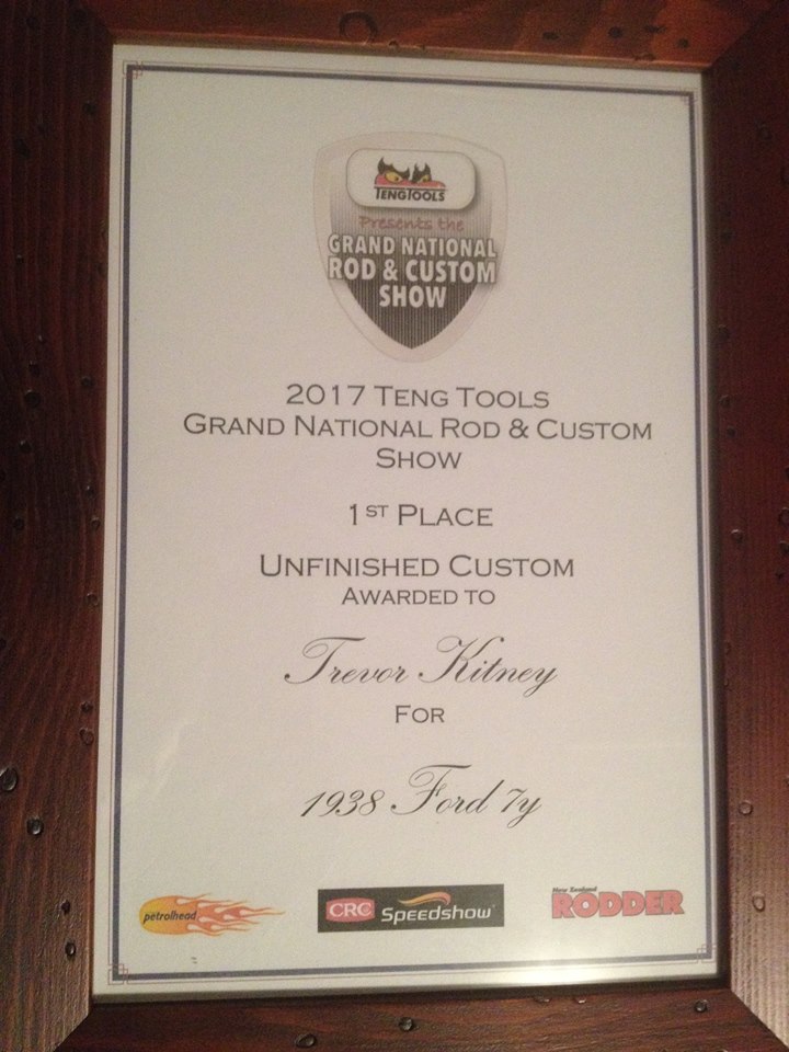
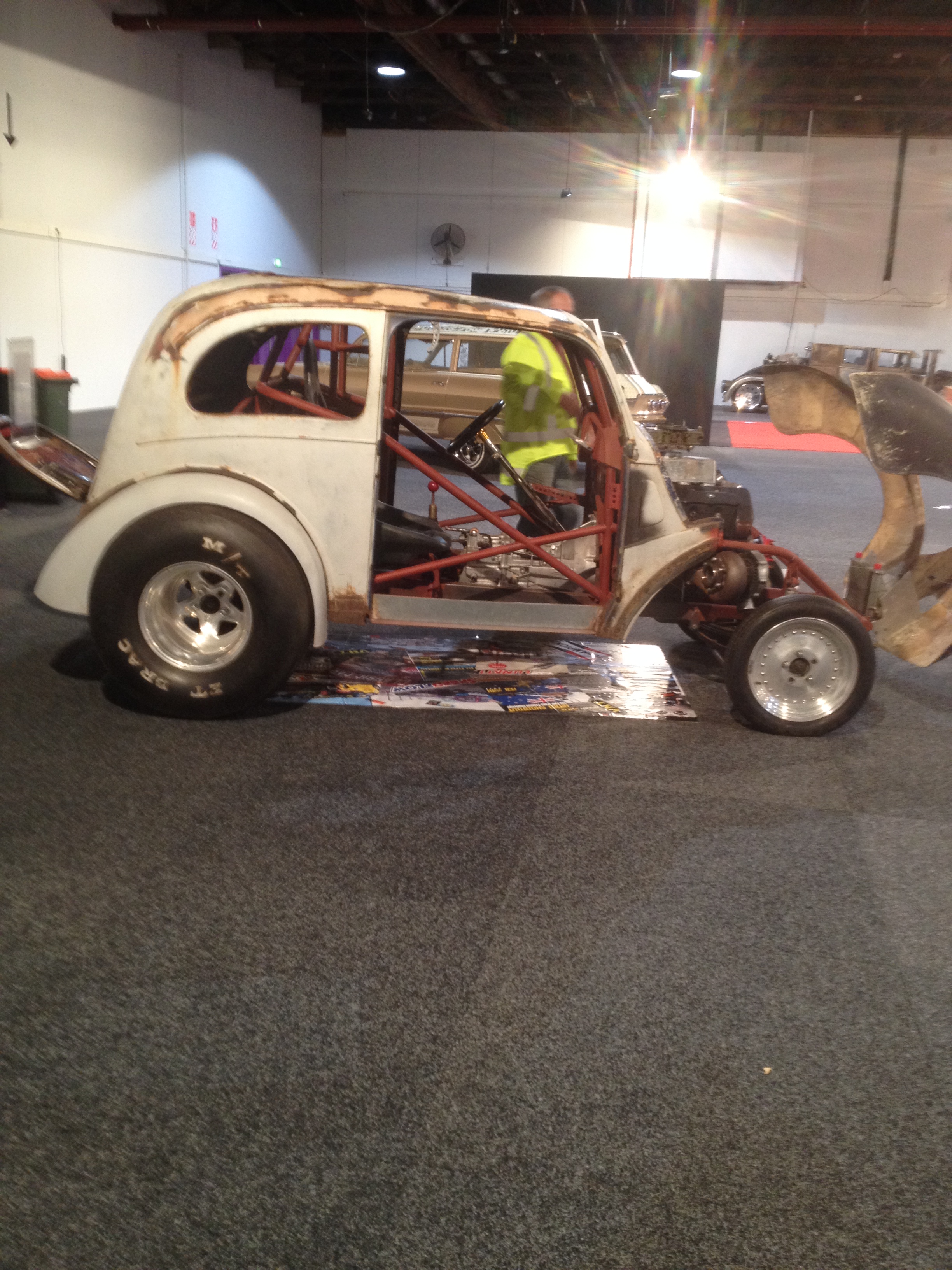
Early start this morning to get the car to the CRC Speedshow. It's in Hall1 in the 'unfinished custom car' category.
I'd appreciate a vote if you're going:)
-
3
-
-
The car will be at the CRC Speedshow in a couple of weeks' time.
In the 'unfinished' category'.
So there's a bit of a push at the moment to get some of the clever stuff finished......
-
6
-
-
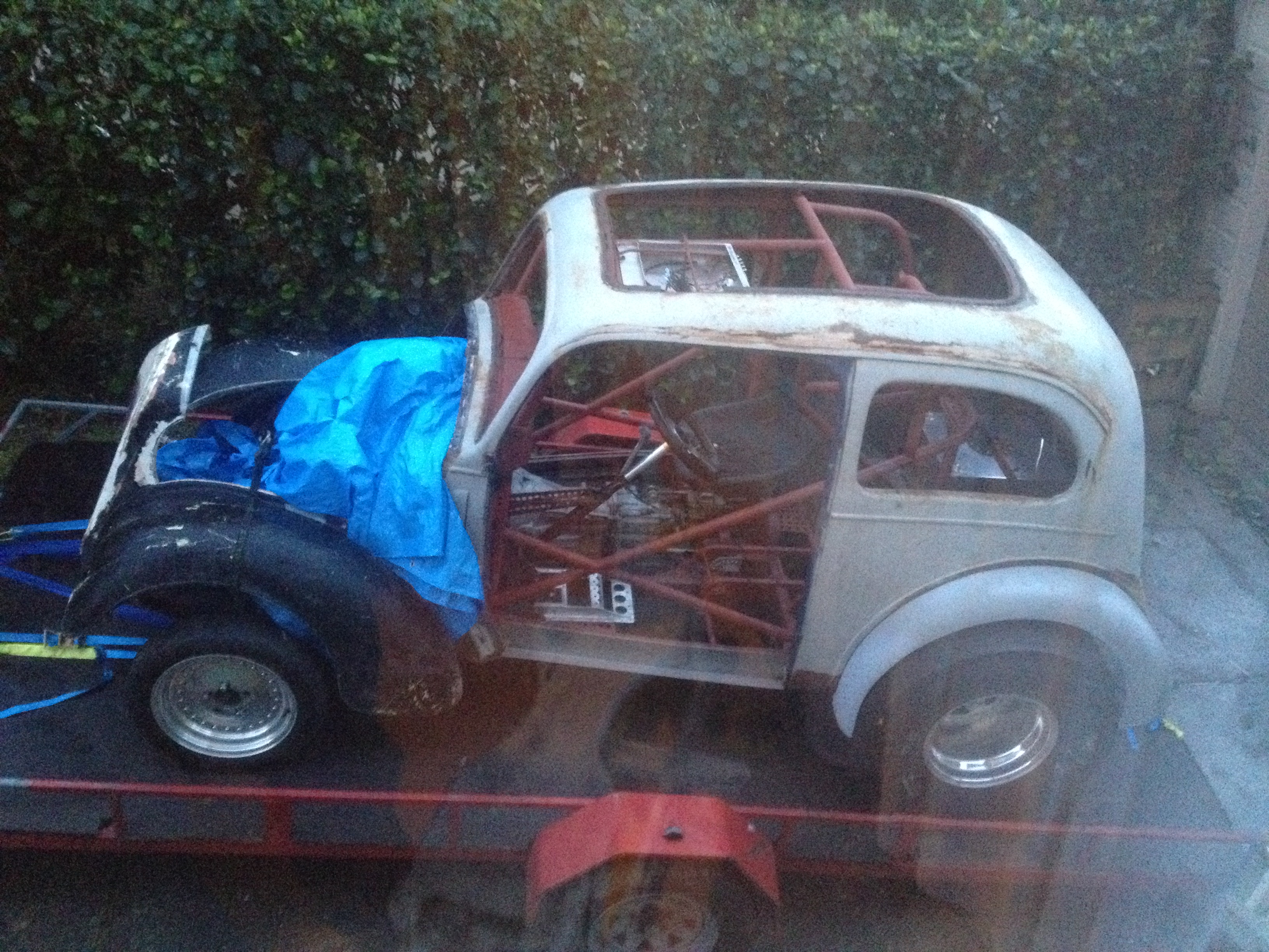
I know I don't post on here a lot, but yesterday was a very important stage in the 'Reaper build - I got it on its wheels!
All of the suspension is in place (it will have to come off again for detailing and painting) and the wheels bolted up to the hubs.
Really pleased with the stance of the car.
Loads more detail pics on facebook: https://www.facebook.com/mk1gasser/
-
7
-
-
-
Lots and lots of updates since the last post here.
Follow any of the links below.....
http://www.jalopyjournal.com/forum/threads/cheatin-the-reaper.1011157/
-
1
-
-
There have been a myriad of updates since my last post here.
Over Christmas I managed to mount the engine, diff and some of the suspension (it's all got to come out again when it's painted), and there are lots of little projects constantly on the go.
Catch up via one of the links below.
oh, and Happy new year!
-
2
-
-
Getting on really well with this.
If you haven't kept up with the build, follow one of these links:
http://www.jalopyjournal.com/forum/threads/cheatin-the-reaper.1011157/page-4
http://www.rodsnsods.co.uk/forum/garage/cheating-reaper-176602/page29
-
1
-
-
http://www.jalopyjournal.com/forum/threads/cheatin-the-reaper.1011157/page-5
Lots more updates, and more to come!
-
1
-
-
Loads more progress. Check out the facebook page!
-
More progress on the rollcage.
Engine bars:
Dash bar and main door diagonals:
And the top screen/roof bar:
Just another 17ish more bars to go and I can fire up the TIG again.-
1
-
-
This arrived today:
It's a Getrag six speed from a 2012 Mustang which will live nicely behind the quad cam and give my right hand something to play with.
Also arrived was this:
Which is a sprint car chassis. It's damaged, but I want it to cut up so I can use the tubework and brackets etc. Cost was $34.99NZ, a fraction of what the Dzus brackets would have cost new.
-
2
-
-
I've been re-hosting the pictures on the HAMB, so that should be OK: http://www.jalopyjournal.com/forum/threads/cheatin-the-reaper.1011157/page-4#post-11554503
I can't explain what's happening with the pics. All of the settings on Rods'N'Sods seem OK.
Failing all that, just follow the build on facebook:
-
1
-
-
So planned out the brackets (this stuff is all planned you know!):
Cut and drilled the bracket material (this is 8mm mild steel plate). The four mount brackets are already tapped m10 thread in this pic:
Trial fit before going any further. The mount bolts are M10 12.9 countersunk allen head bolts.
Then weld on the correct spacers. These were through-drilled the correct diameter and then tapped m12 after welding:
and bolt it all together. The uprights will be countersunk more to allow the bolts to be flush, and the caliper bolts are only there for trial fit:
There will need to be very thin shims between the calipers and mounts, but at least I know it will all works.-
1
-
-
I can't explain why you can't see them.
Try my build thread on the HAMB:
http://www.jalopyjournal.com/forum/threads/cheatin-the-reaper.1011157/
-
"At last" I hear you say "Something different to that bloody bootlid"
The drop-tube front axle came with vented (Holden) discs, but no calipers.
I found these on a local auction site. They are JFZ aluminium 4-pot calipers (same as Willwood). I paid a lot (for me). $101NZ, but they did come with 3 sets of pads, a master cylinder to suit and some flexible brake hoses.
Cleaned up on right, as bought on left:
Although I didn't know it when I bought them, they are the perfect size for the discs I have. Just need to make up mounting brackets and they'll be fitted:
They have a nice old-school feel about them, but will undoubtedly stop the old Ford like an anchor has been thrown out the back!-
2
-
-
I was able to see the pics this morning, and got through the first 2 pages until it stopped working.
Keen to see the rest, your shits amazing!
Pic's are back now. Don't know why they left or why they returned....
-
for some reason i cant see any of your pics.
even the first ones.
Maybe you have a filter on that won't allow you to see them? I think everyone else can see them OK.
-
Shit ur good!
After ya used the tool to fold that edge over how did you shrink out the wrinkles?
Filling in those big flat side holes is easy
Shrunk out the wrinkles with hammer and dolly.
-
Any more progress? Keen to follow the build.
Cheers
Yes, more progress posted!
I try to do an hour a day on anything I can. Bootlid is more-or-less done now, body is sat on chassis, new front calipers arrived today (yay!) and will need mounting brackets made. More pics soon.
-
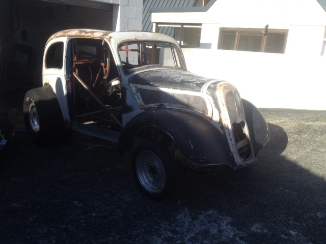
Whilst the bootlid is ongoing at work, I thought I'd attack the front end at home.
In it's past, someone had bonded in original steel grille and side-vents. These have to go as I'm looking for the smooth look like Blair's car.
Fortunately the rust had loosened all of the filler, and within an hour it looked like this:
Next job will be fill the holes. I already have a plan!-
4
-
-
Bootlid - the final (ish) chapter.
All that was left to do was fabricate the inner drip/seal section.
This started life as part of an old fire surround (upcycling is good, yes?):
from which I sliced a 90 degree angle section:
And curved it the old fashoined way by using hammer and dolly:
Then edge-welded it to the skin:
Once it was all made and welded into place:
I made up this little tool.
to bend the inner return. This is done very slowly by easing it down in gentle angles until it reached 90 degrees
Once that was done, all there was to do was make up a couple of small closing panels for the bottom:
And welding the top section to the 'C' section that will be the support member for the lock.
The return is there so I can rivet an aluminium panel to it which will clean up the look of the inside.
I've left the bottom corners of the drip/seal rail unwelded as I may need to reshape them slightly when the lid is in place.
That's about it until the hinge panel is welded to the body. Stay tuned!
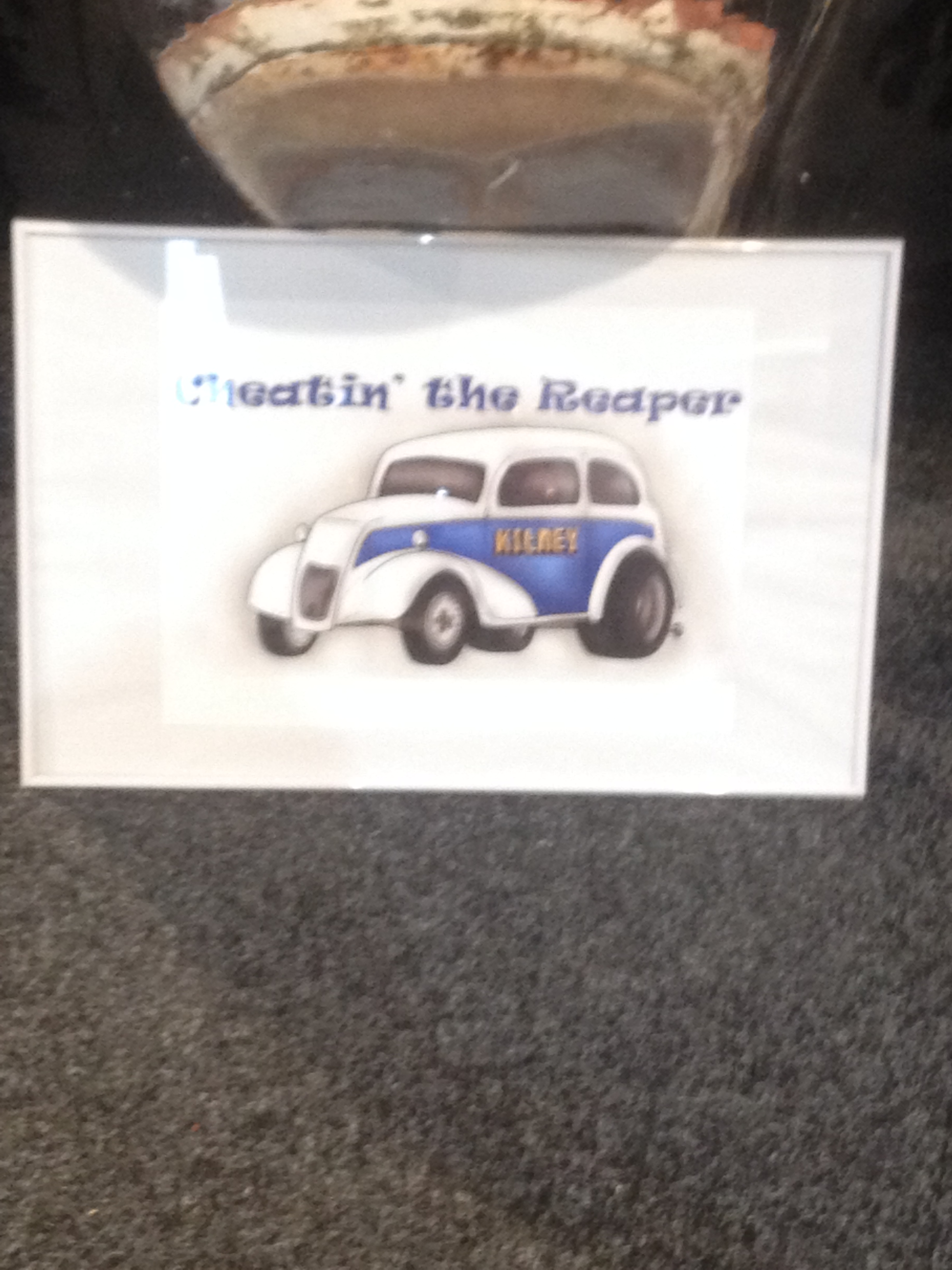
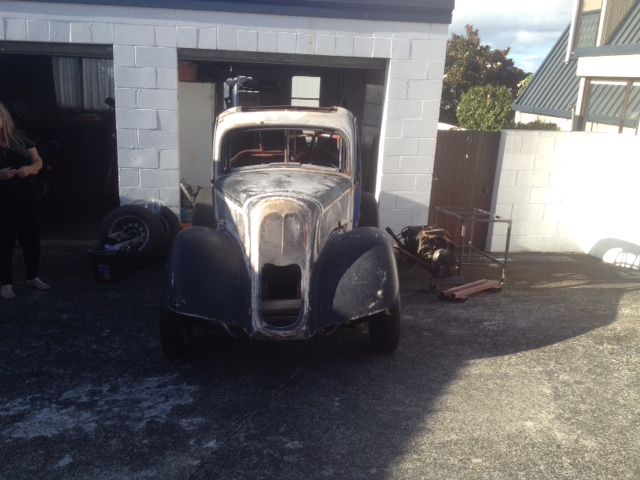


legendlives 1938 Ford 8. The Reaper's return
in Projects and Build Ups
Posted
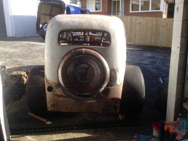
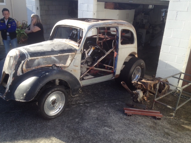
Since July I've done quite a bit. All of it documented on the facebook page, but in a nutshell:
After seeing the car out in the open, it needed to be lowered. As the wheel to arch fit was perfect, the only option was to move the arch up the bodywork by 2".
Then added exhaust 'holes' to the front of the arches.")
The boot has now got the returns and drip rails:
The rear lights are in:
And the roof panel is welded in:
A few small rust repairs to do, then the body can come off to finish/paint the chassis.