legendlives
-
Posts
476 -
Joined
-
Last visited
-
Days Won
1
Content Type
Forums
Downloads
Events
Gallery
Everything posted by legendlives
-
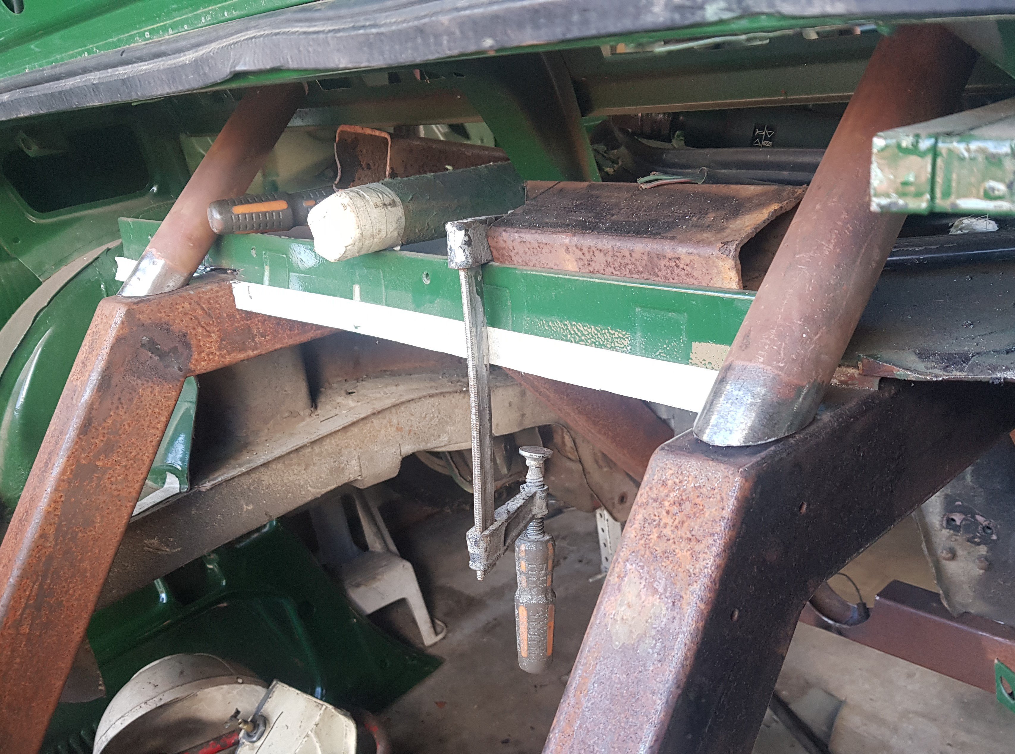
Dragging myself away from the interior for a moment, I thought it's about time I did more mechanical stuff. I need to mount the front struts to establish whether the wheel position would be right, but to do that I'd have to build up and mount the front crossmember. Reading about the competition TR7's and 8's, it seems the standard caster is virtually zero, with some production cars going into positive caster. The mod is to mount the anti-roll bar further forward which pulls the TCA's forward and gives more caster. So carefully mounting and tacking the ARB perches a whole hole further forward (so around 10mm), the new mount holes were drilled: And that being the last crossmember mod it was painted and the assembly started. Just about instantly I came across a problem. In the time between stripping the car and trying to reassemble it, two of the TCA bushes had gone walkabout. Actually, they were probably never there as I have two odd 'flat' bushes with odd wear patterns. The problem persisted: But getting replacements shouldn't be a problem right? To buy a set of 4 genuine fitment bushes is in excess of $200! 'F@*k that' I thought and looked around for an alternative.

-
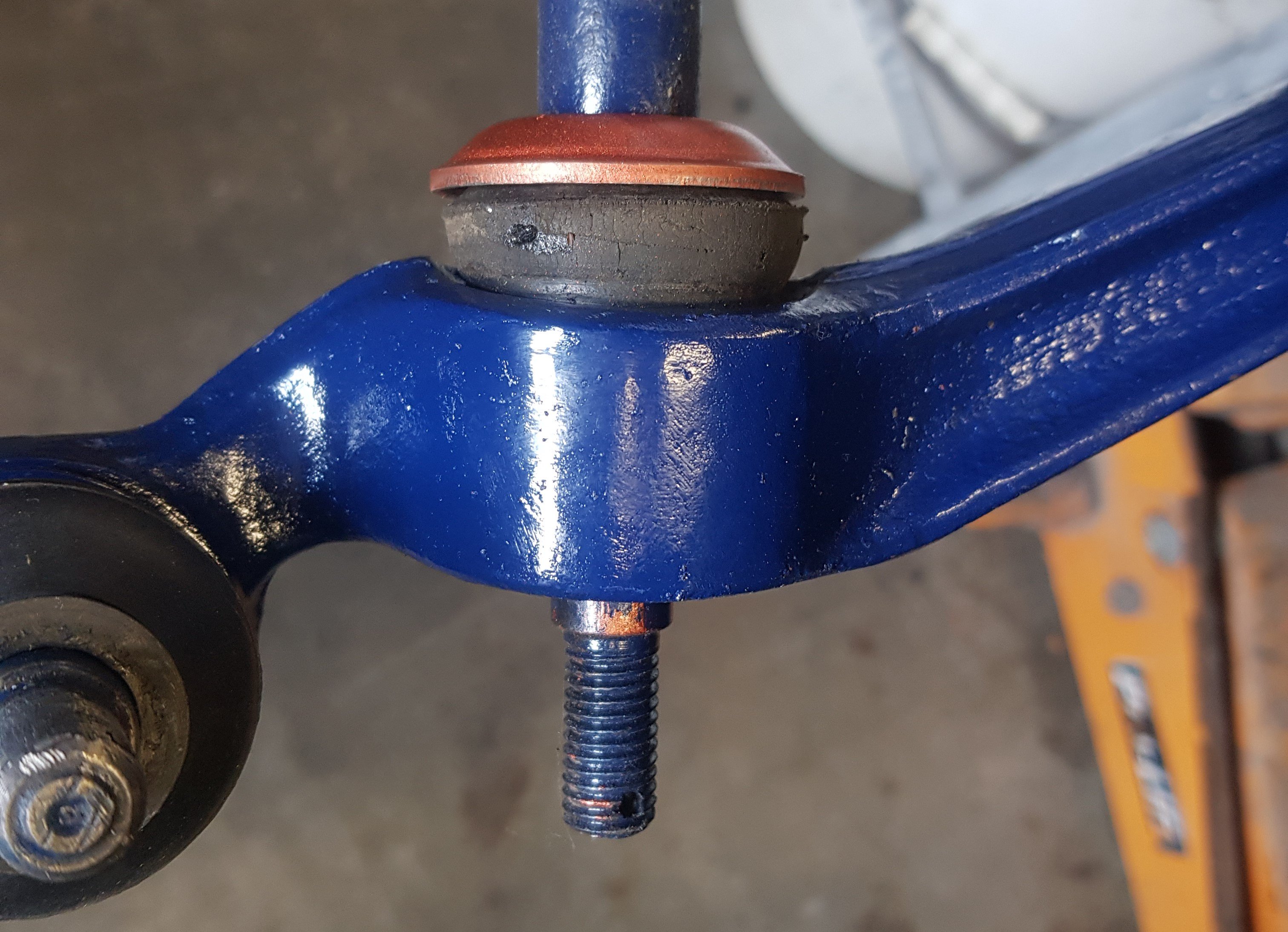
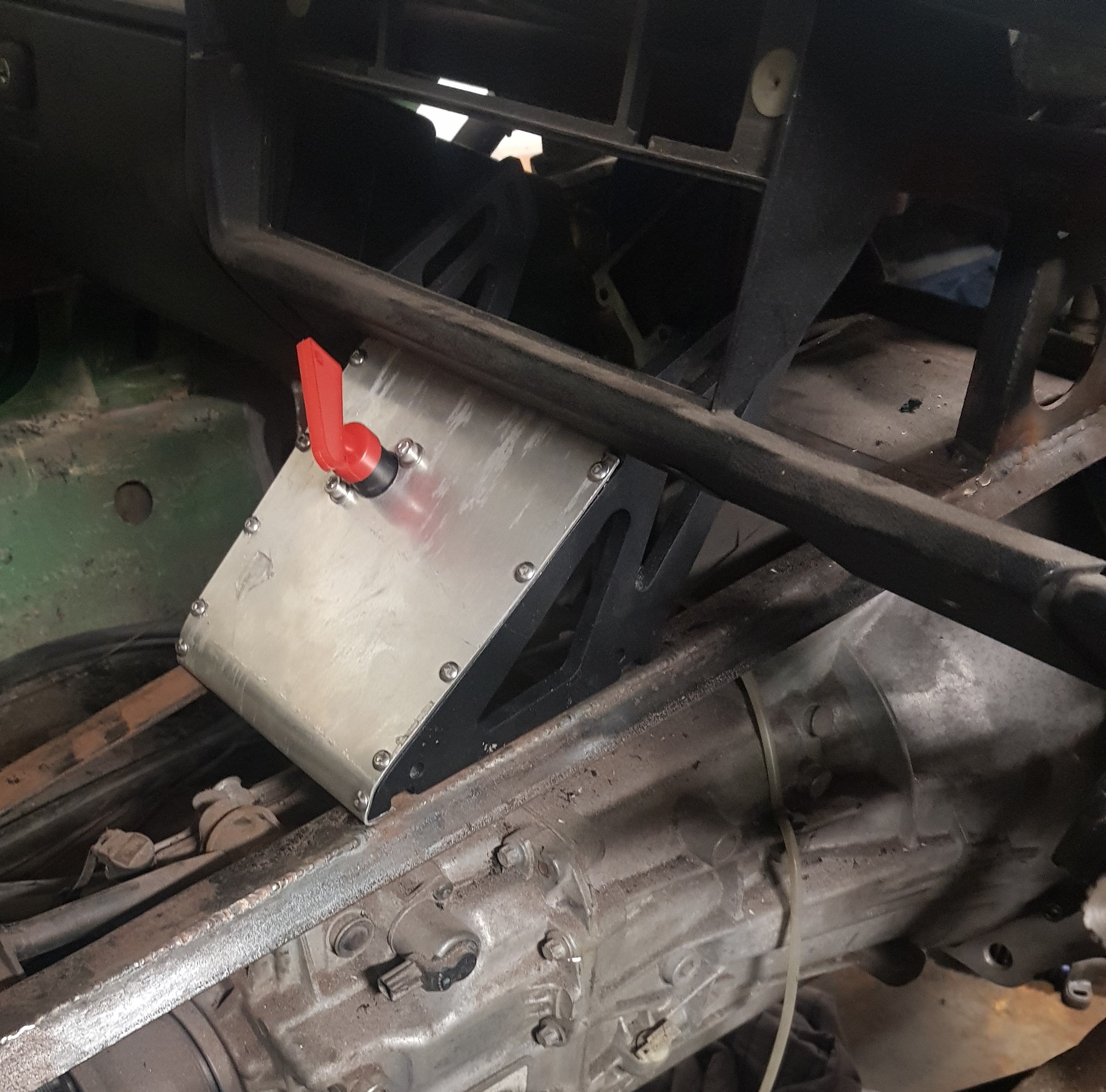
The dashboard is made from 2mm aluminium plate with all of the necessary gauges and non-essential switches: The 'essential' switches (ignition, fuel pump and start) will live down on the transmission tunnel console. This is made from 2 old spoiler mounts and another bit of 2mm aluminium, all held together with M5 SS screws: boot It also provides a good centre support for the dashboard.
-
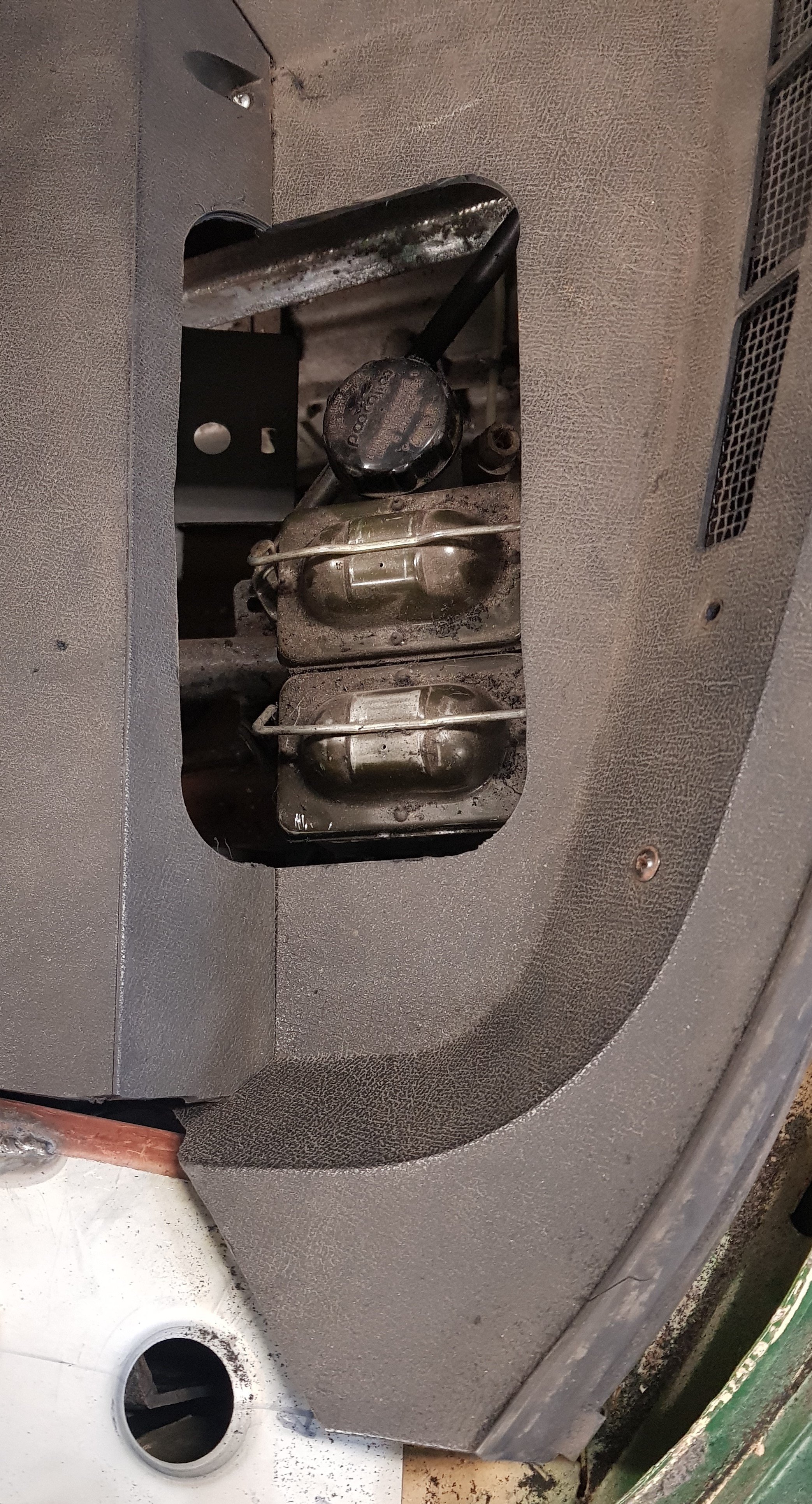
You'll see in the first pic the cut out for the fluid reservoirs: This will be tidied up a bit, and it will have a removable cover over it as I think I'll get horrible reflections in the windscreen. Inside the car all is good. There will be a flat panel with the gauges, warning lights and (some) switches which will cover the whole opening. The dash will need a support in the centre as all of the original brackets were attached to the heater and trans-tunnel but this is already well past the planning stage so may be in the next update.
- 58 replies
-
- 12
-

-
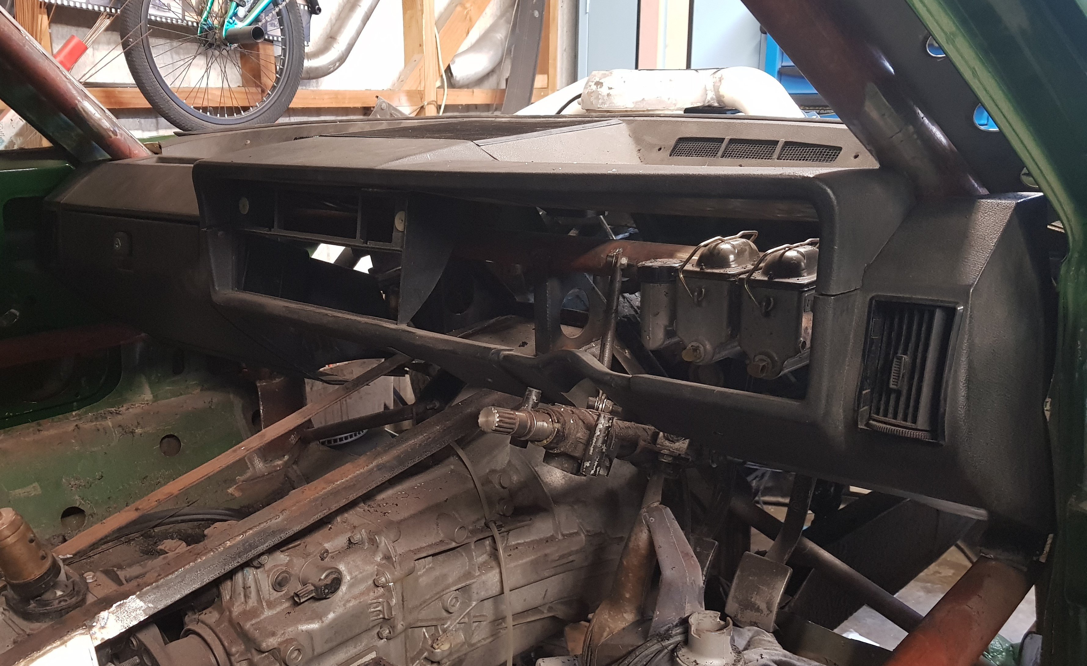
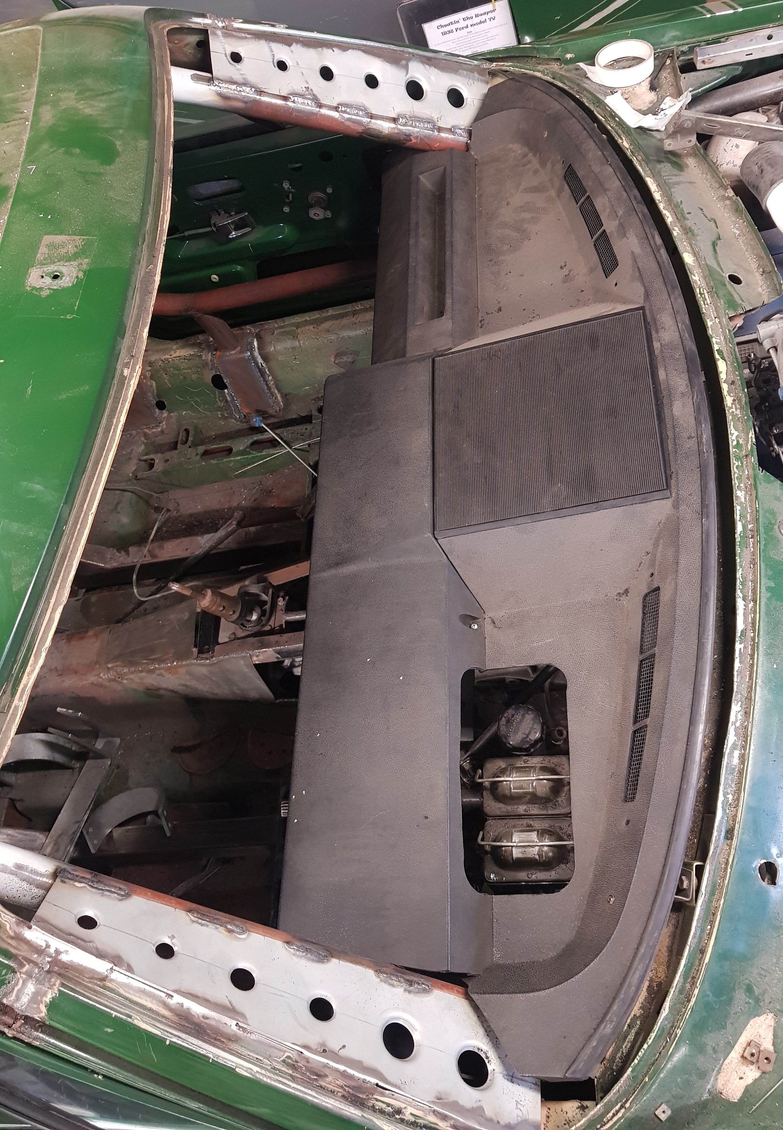
It was always my intention to use the original TR7 dash panel(s) in the car, but in the time between removing the main panel and trying to refit it, I'd forgotten exactly where it sits. I carefully measured between the bottom of the screen back to the rollcage and cut the holes for the cage to pass through. The problem is that the dash panel does not sit at the bottom of the screen - it sits about 30mm up - so the holes I cut were out. A bit. I had to open up the holes backwards a bit. It doesn't look too bad, nothing that a strip of rubber won't cure.
-
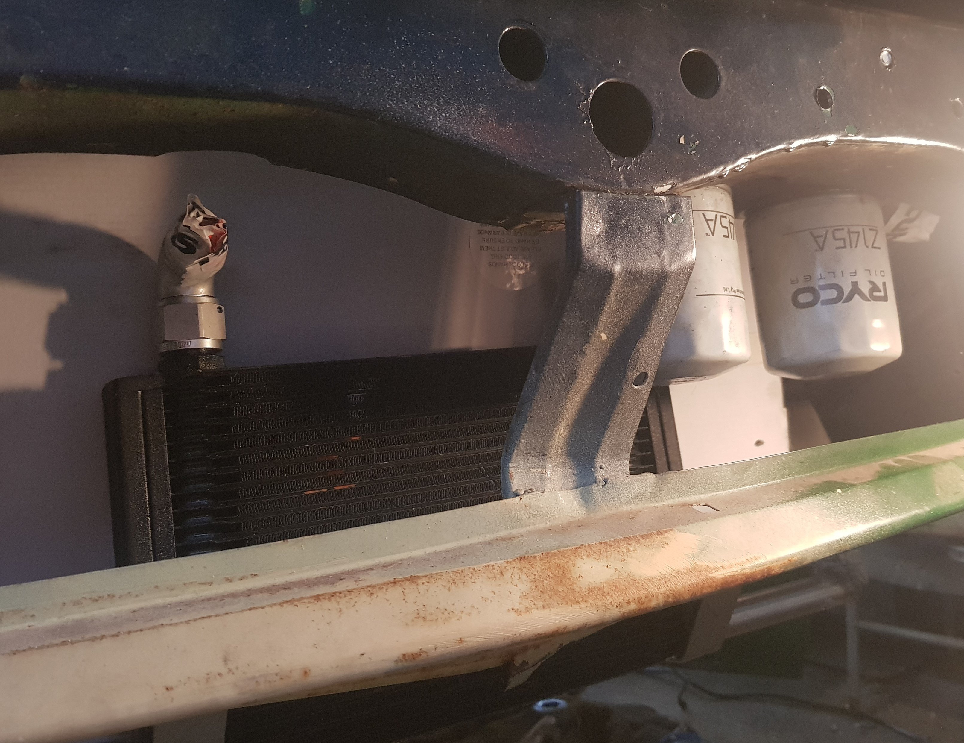
On my previous car, the remote oil filter mount was mounted directly to the oil cooler, but there isn't enough room so they are now mounted behind the front bumper crossmember. High enough to be out of harms way but still easily accessible:
-
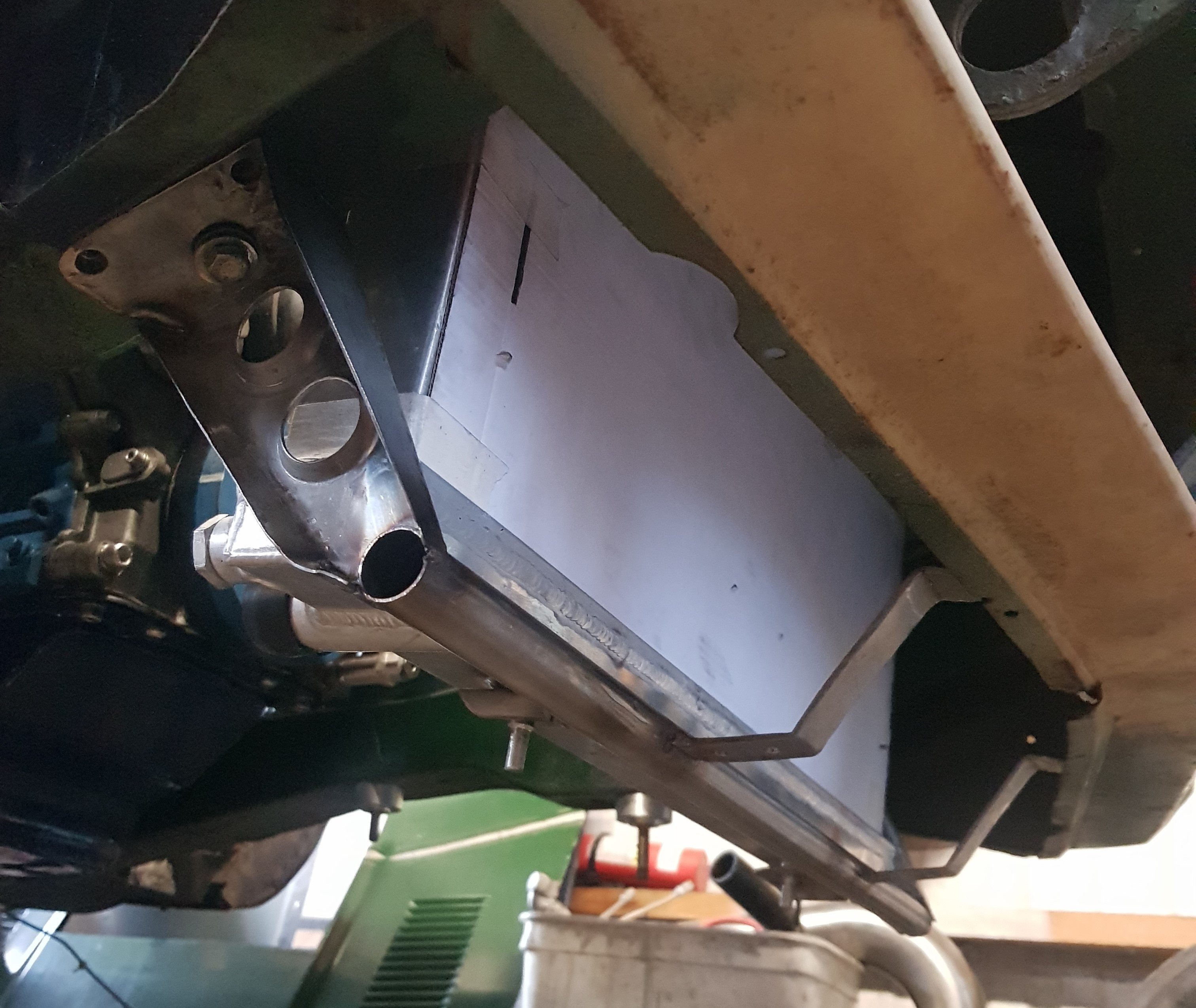
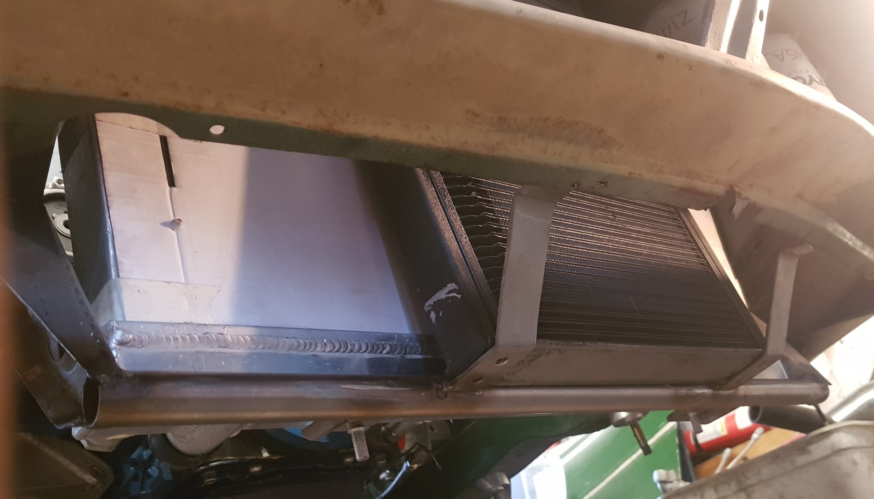
The lower radiator mount is all stainless-steel: Which turned out OK. It mounts to existing threaded holes in the front chassis members. The front brackets come up to the front vallance. Holes in that are for the oil cooler:
-
It fits really well. I have not done the lower mount yet, but there is a selection of threaded holes in the bottom of the chassis in this area.
-
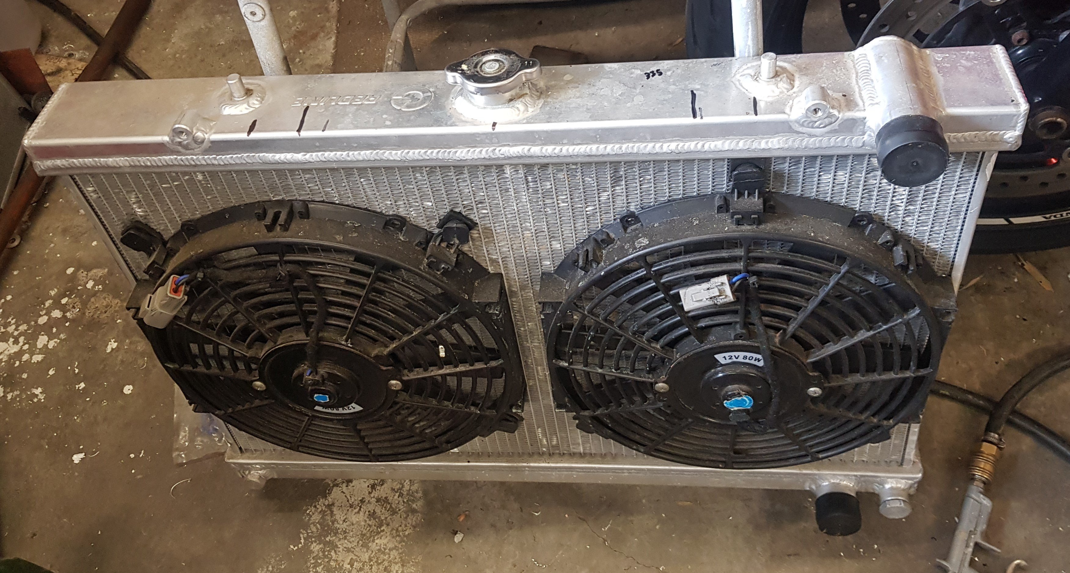
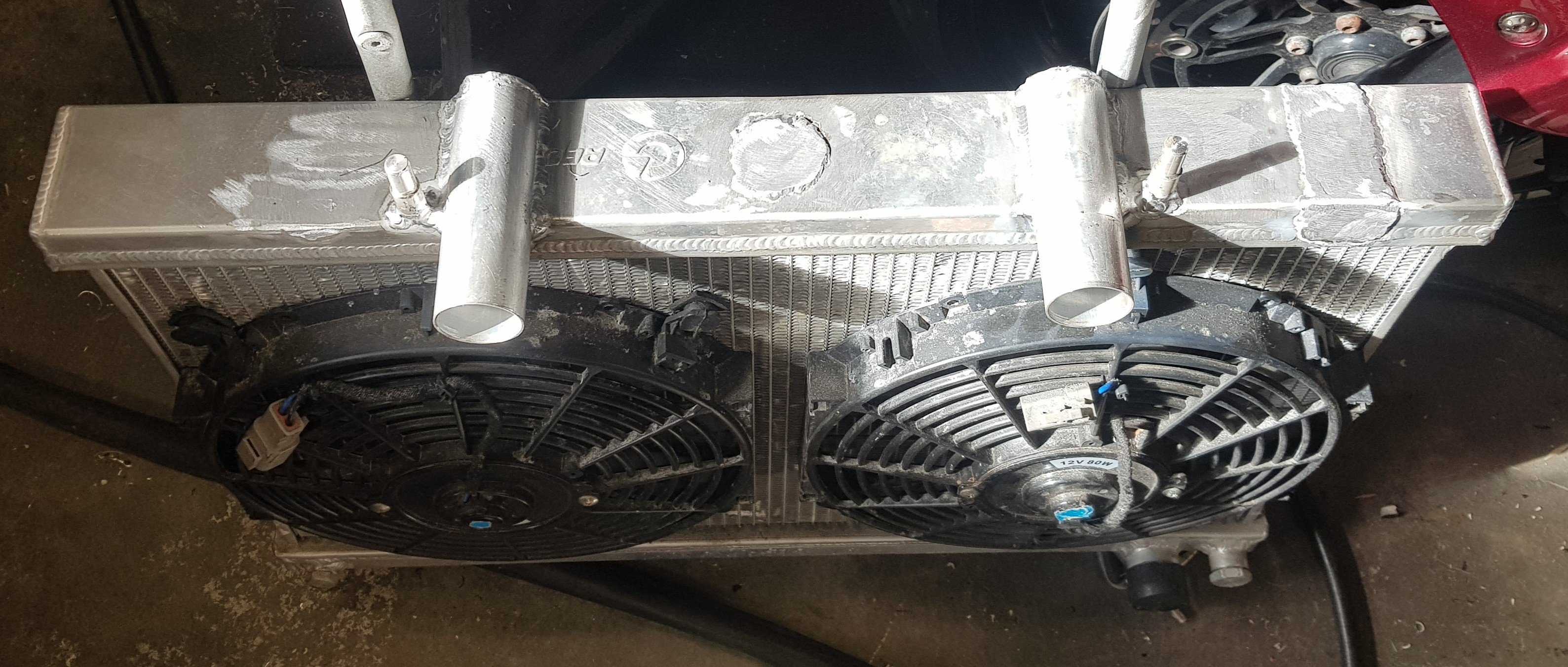
With the back end of the car getting all of the love recently, I thought I'd better do something at the front. I bought the radiator some time ago. I don't know what it's from but it sits between the chassis rails with about 10mm either side. Two major issues though: I wanted it to sit as far forward as possible but to do that the filler would be inaccessible, and the top hose was the wrong size and in the wrong place. The top mounts were wrong too as I wanted to use two existing holes in the front slam panel as the top mounts. No problem, I have a welder and I'm not afraid to use it. The engine has two top hose outlets (one from each head), hence the two tubes. The filler is now at the very top of the cooling system on (what would have been) the thermostat housing.
-
It's tight in there!
- 58 replies
-
- 13
-
-
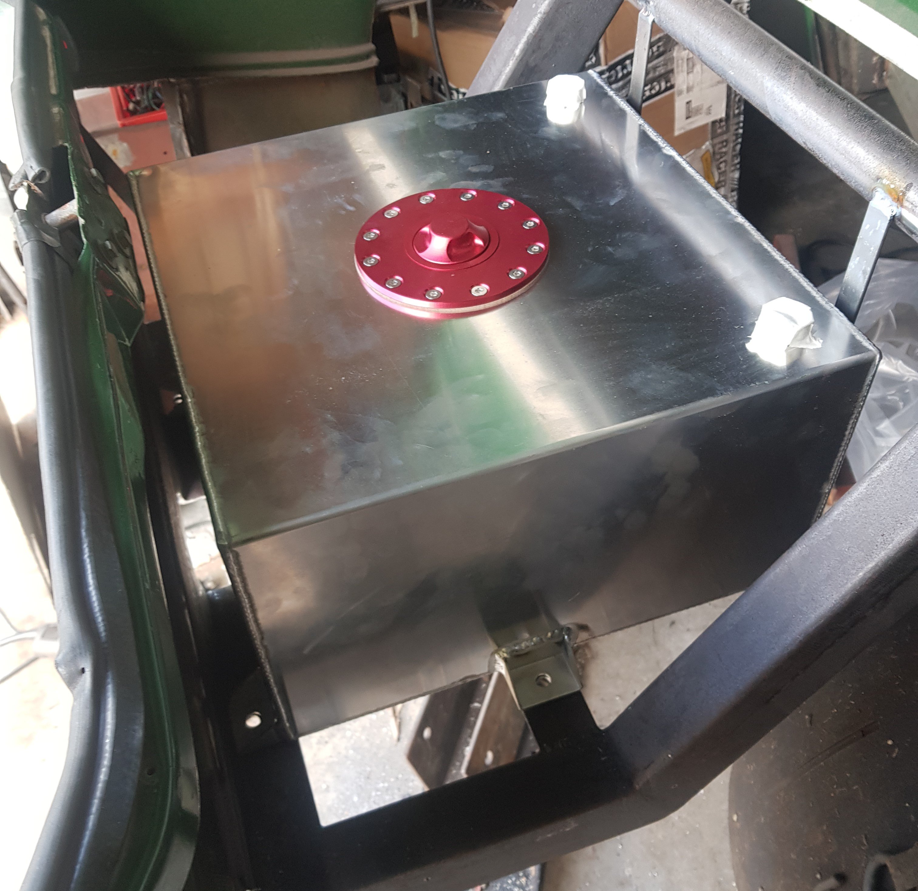
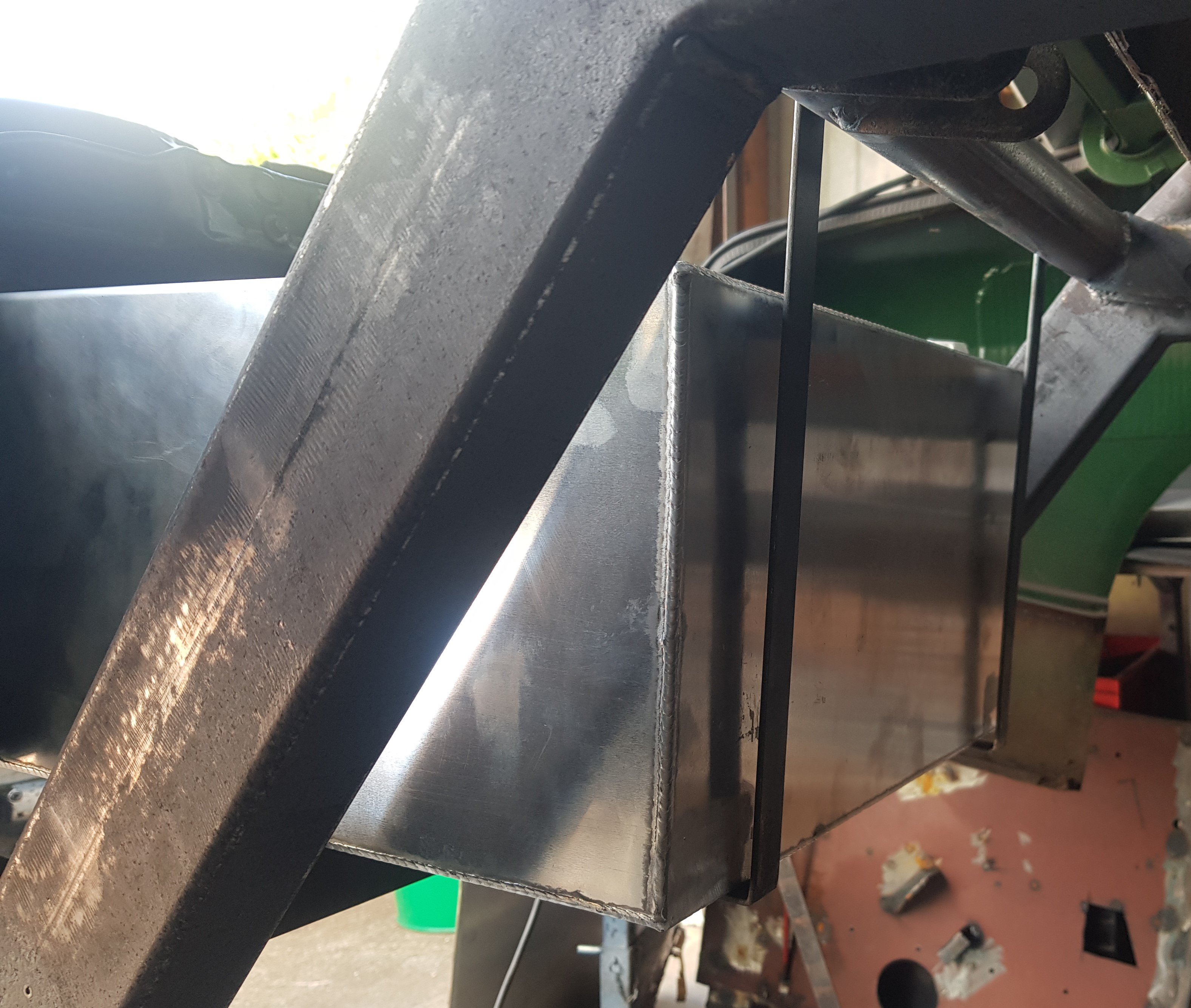
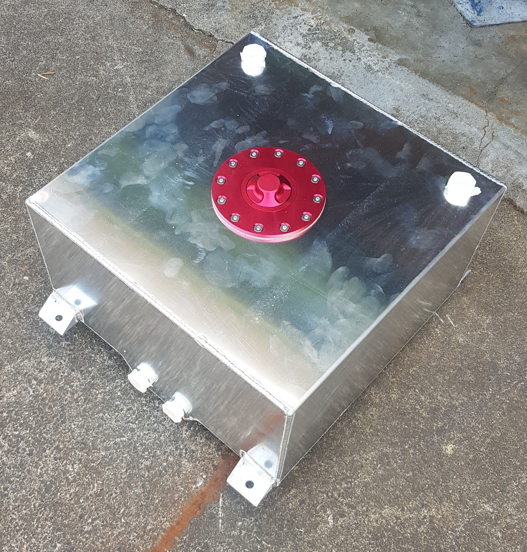
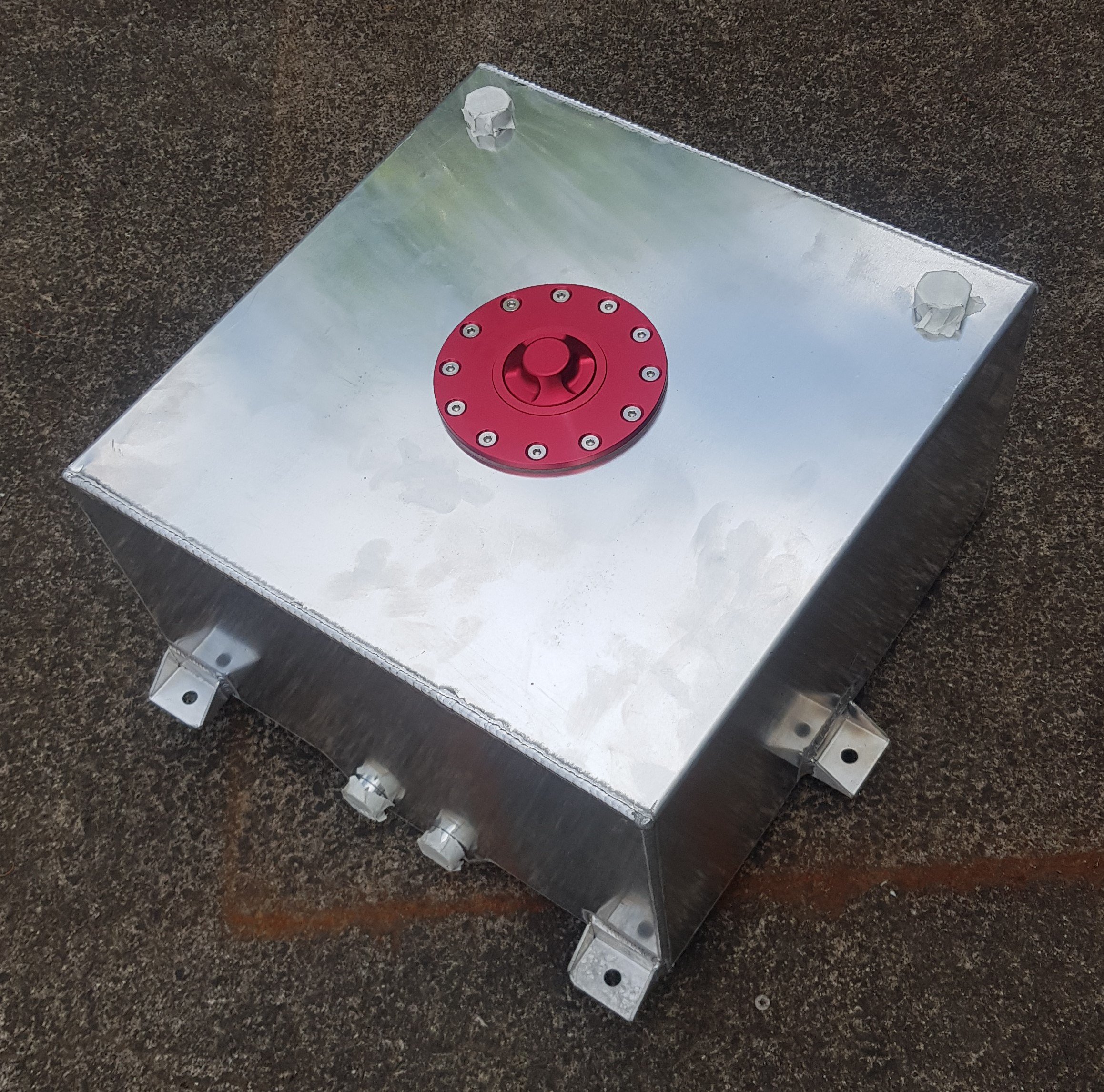
At the front of the tank I've added these two support straps: I'm not sure they're 100% necessary, but best be safe than sorry. They will have a panel between them and the tank, and the tank will be mounted on rubber strips. The tank sits so far back that the fuel feeds will have to come through the rear panel. This won't be a problem as there's loads of space between the rear panel and the bumper.
-
Fuel tank is an aluminium unit. It has a rear 'sump' with two outlets, and ports in the top for breather and fuel return. It's not a big tank, but the available space is so small that there was a risk of the front mount tabs interfering with the rear springs, so these were cut off and relocated to the sides:
-
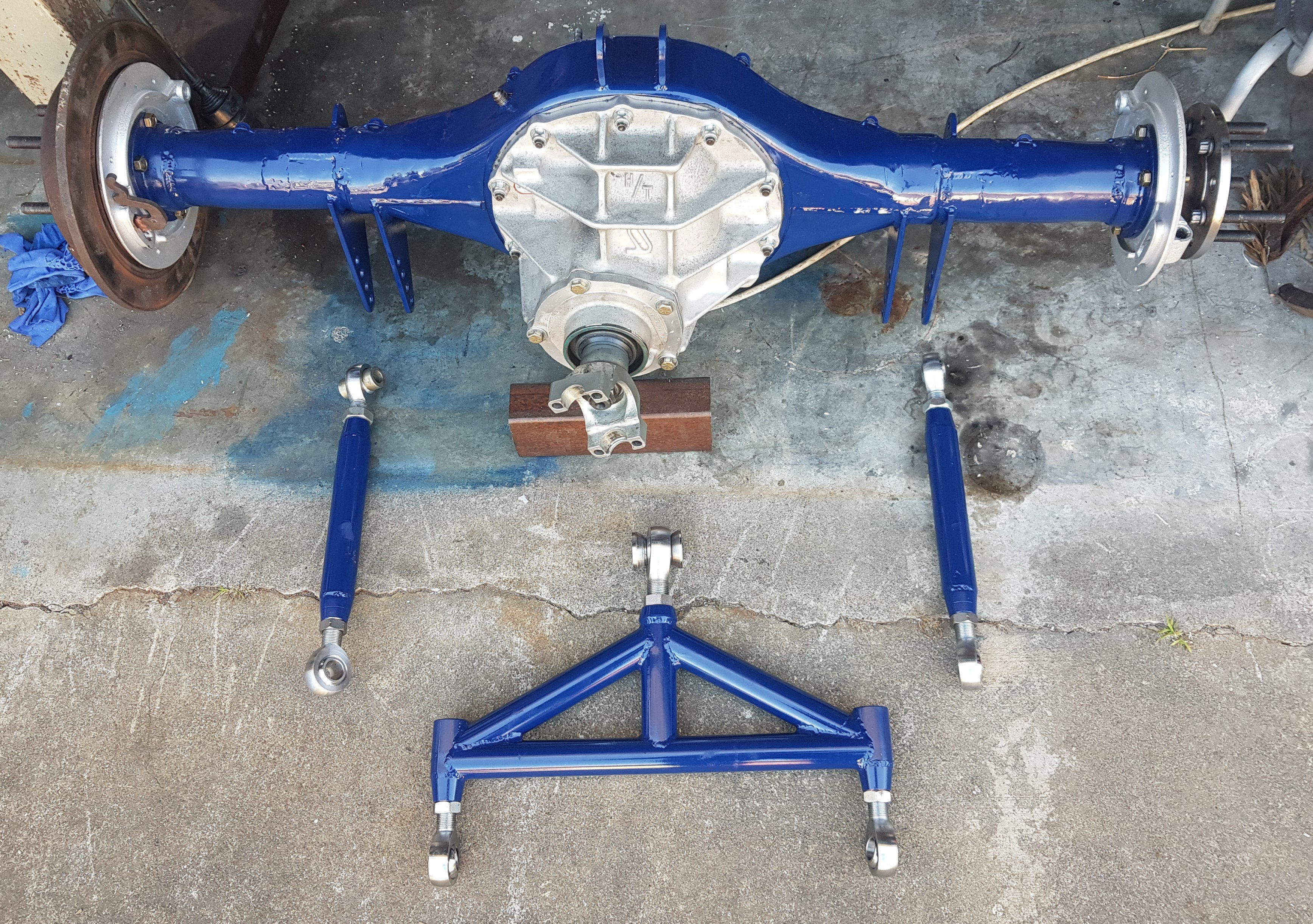
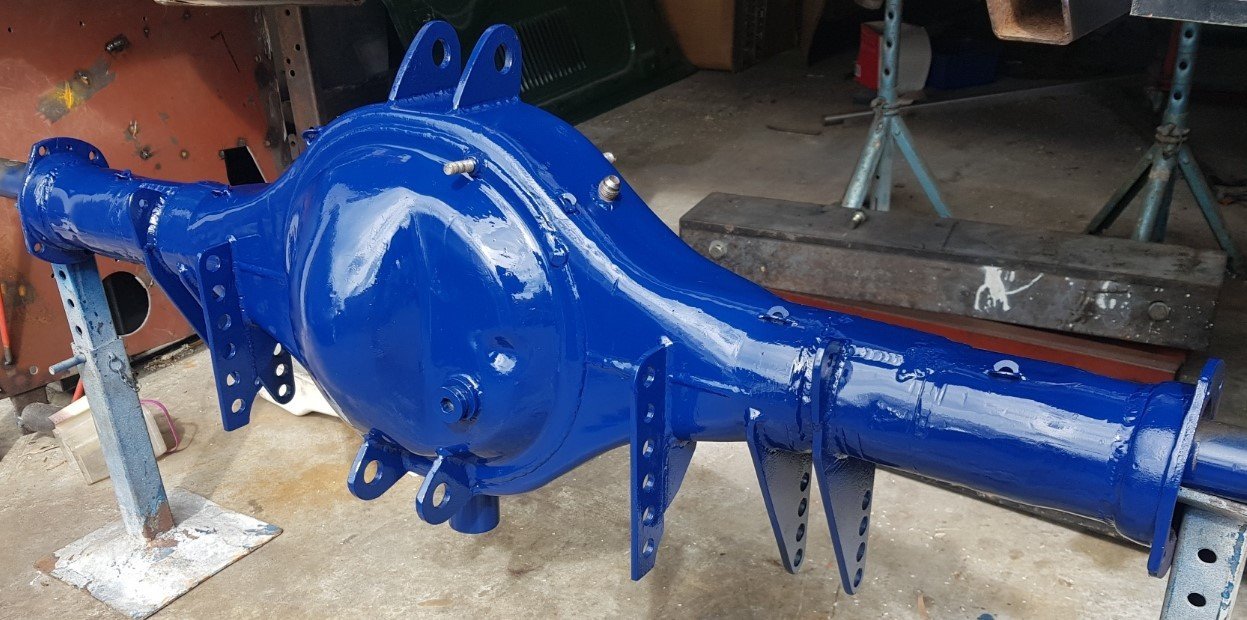
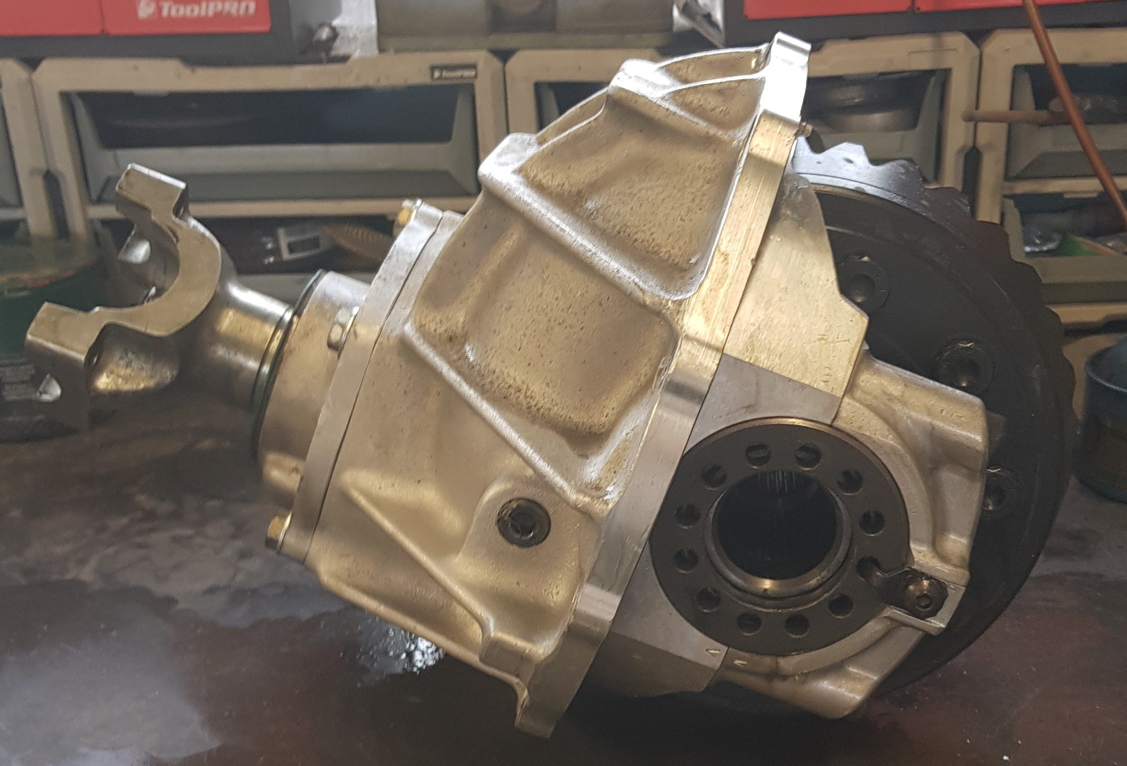
The rear diff/axle is now built: New brake rotors are on their way, and I'm a couple of clips missing from the handbrake mechanism (so if anyone has got any left over from an EF-EL Falcon we need to talk!), but aside from that it's ready to fit!
- 58 replies
-
- 16
-
-
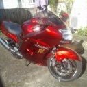
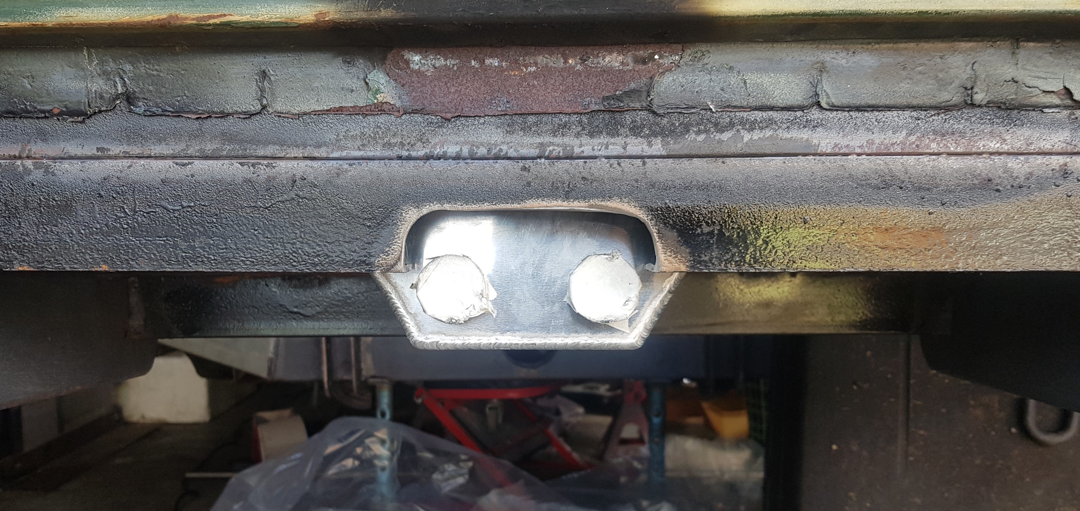
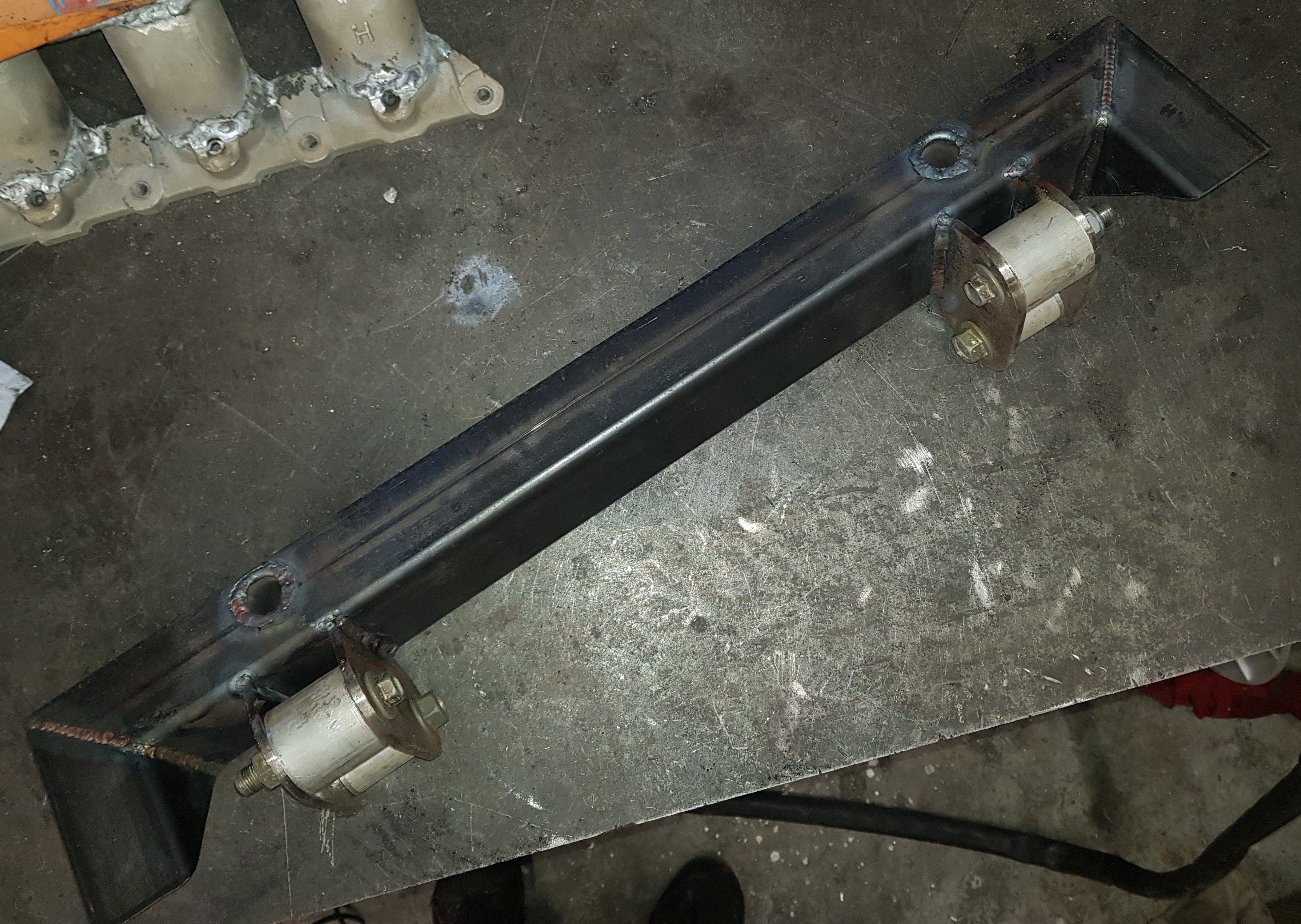
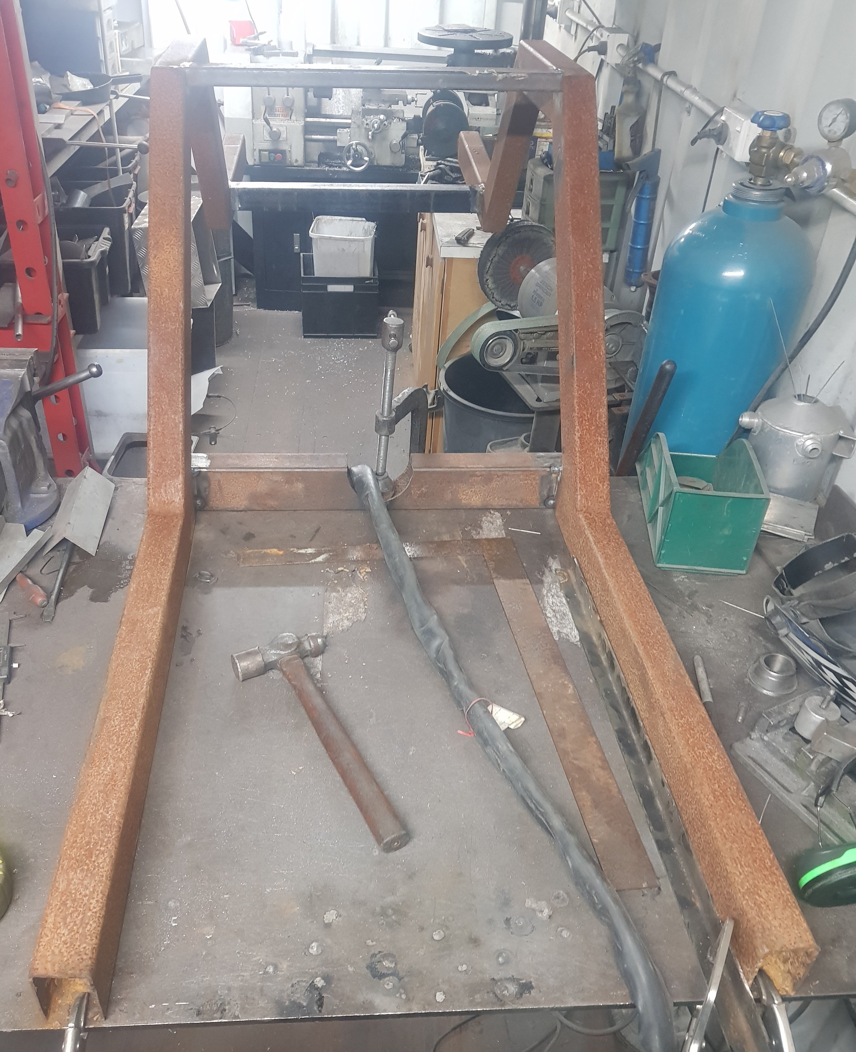
With most of the chassis work in and welded, I called on LightWork to remove the rust from the rear end with their trusty laser device. Great job, with only minimal mess. Far quicker and less-messy than having it blasted, and certainly no more expensive. Although you can't really see it in any of the pictures, this is the crossmember that mounts the top suspension link. It's mounted to the front of the chassis, and the two holes in it bolt up to the original fuel tank front mounts. The aluminium bosses were holding the mount brackets straight whilst it was welded.
-
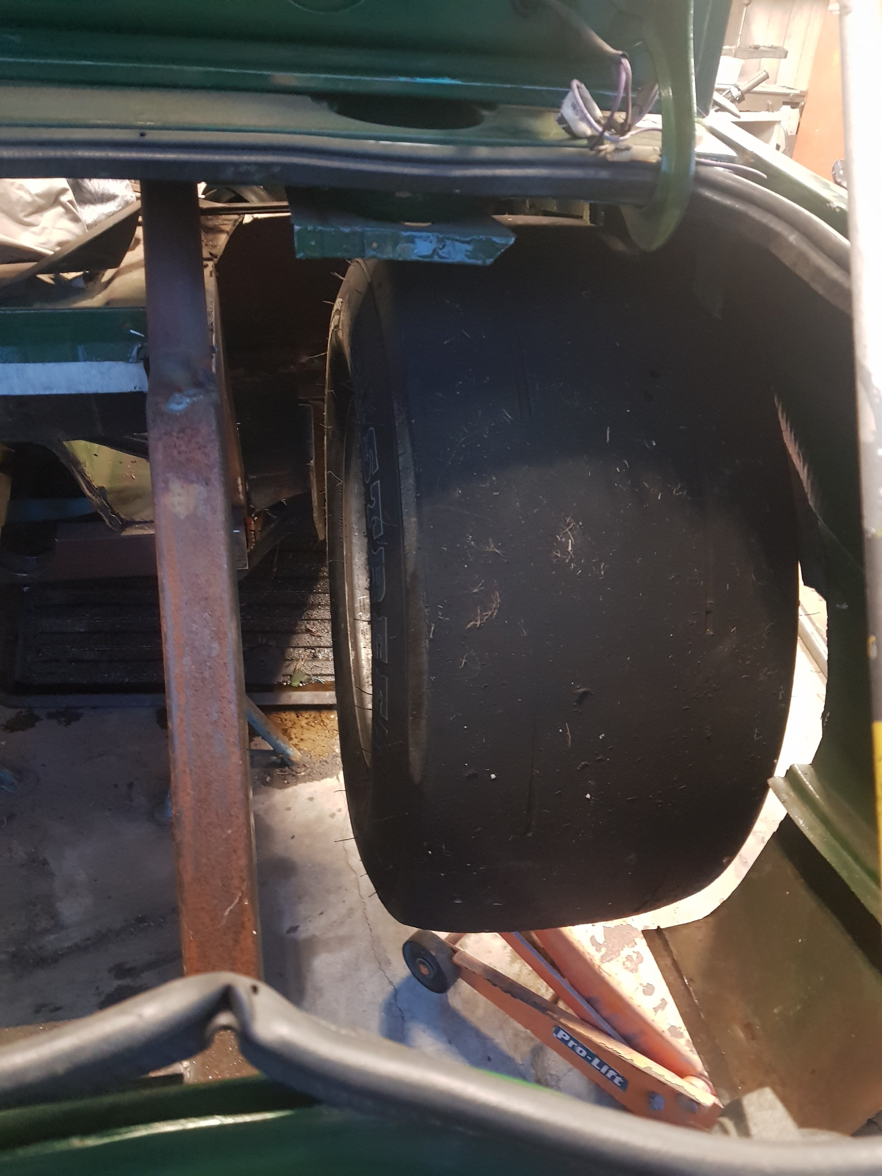
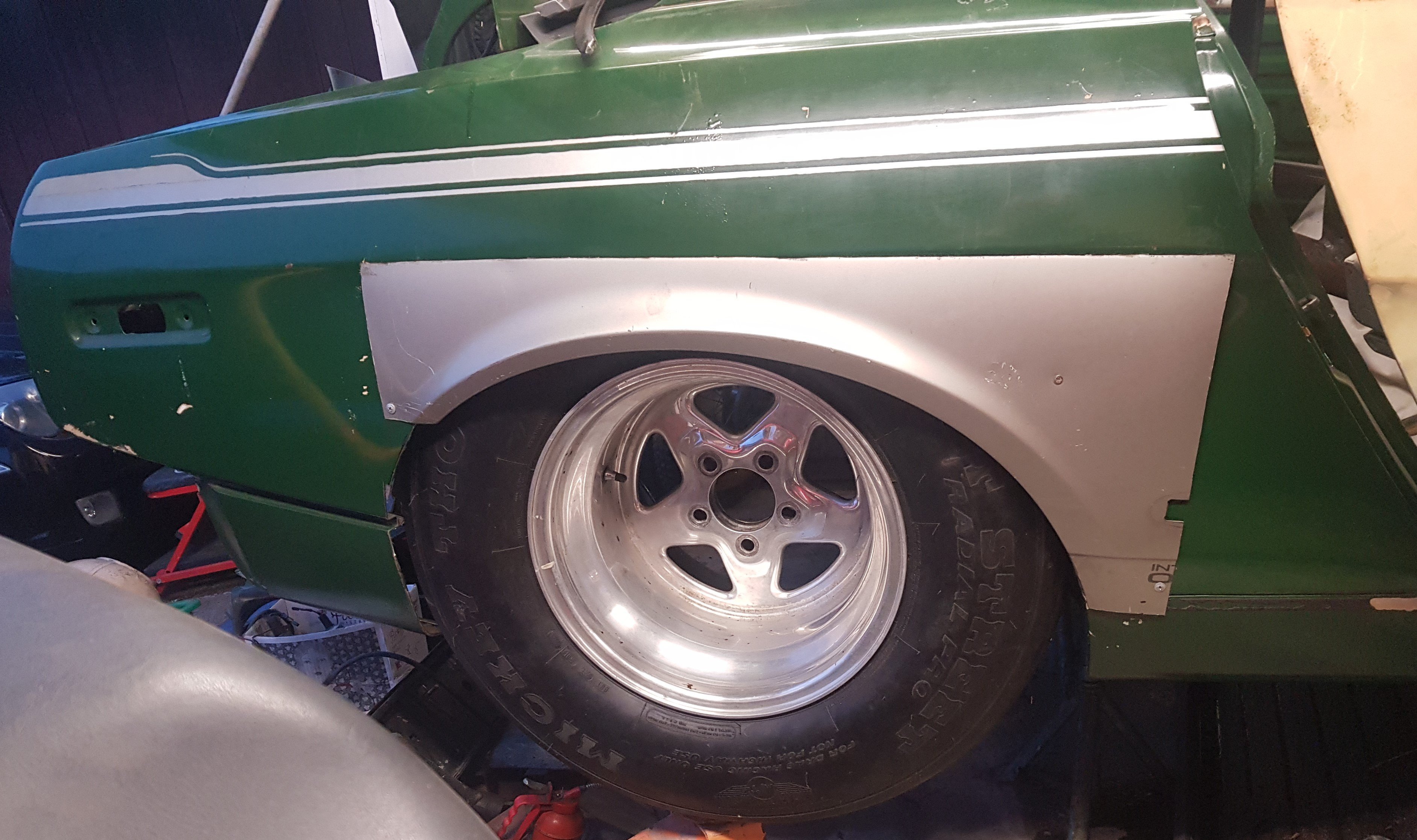
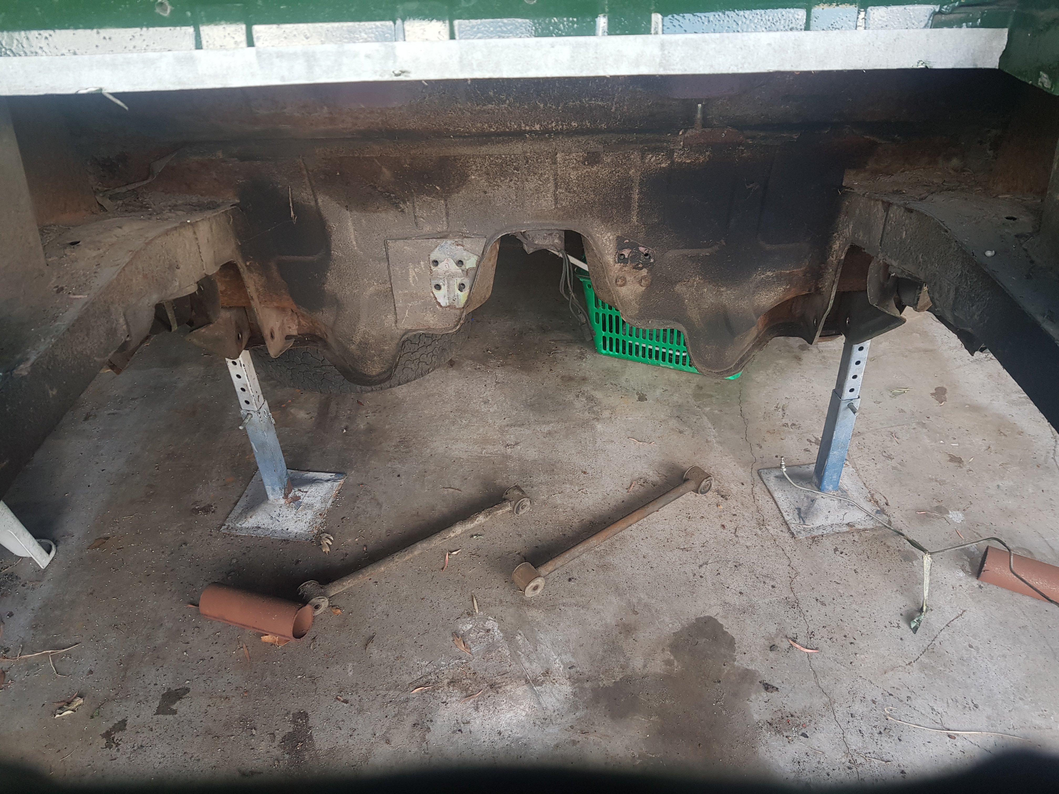
With all of that securely welded in place, the rear chassis members could be removed, making space for the rear wheels and tyres: Which will, IMHO, look the nuts! The original arch lips had been cut out by a previous owner, so those nice, stretched wheelarch panels are actually front fenders fron an AU Falcon!
- 58 replies
-
- 15
-
-
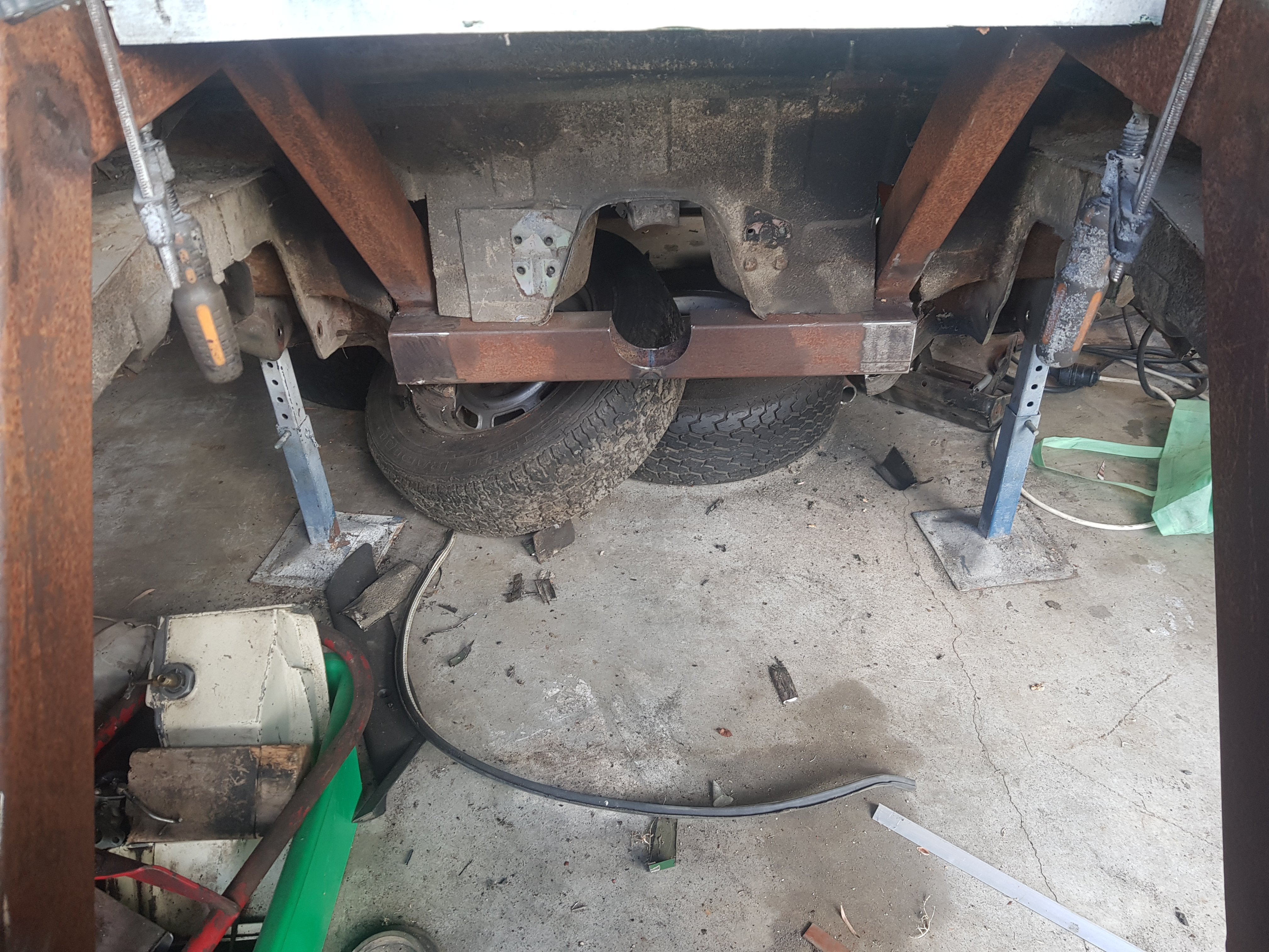
Then with holes cut in the correct places (some of them anyway!) the new chassis was welded to the rear panel, the end of the front chassis, and the seat crossmembers: and, of course, the rollcage which meets the chassis where the rear shock absorber crossmember will be:
-
On my second post I mentioned that the car had been 'back-halved'. Here is the full process: I bought the back half chassis second-hand (I don't know what it was in originally), separated the side members from the crossmembers and re-welded it the correct width to coincide with the front 'chassis' of the TR7. Then cut out all of the rear boot floor, but leaving the original chassis to hold everything square:
-
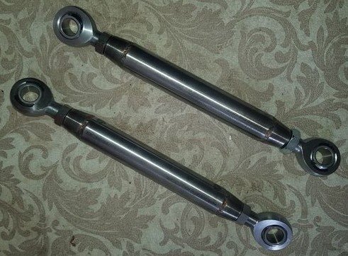
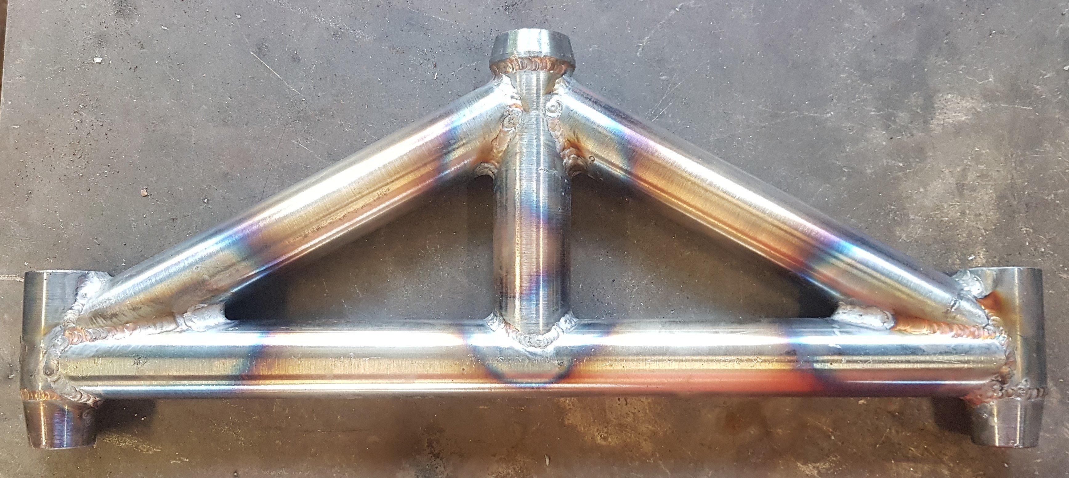
With the Ford 9" axle ready for final assembly, my attention turned to the links for it. Lower links are very straightforward, left and right handed rosejoints and a couple of sturdy tubes: Upper link (yes, just the one) is a bit more complex: The two forward rosejoints are the same size as the lower links, the single axle end one is far larger.
-
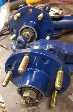
Time for some more paint to be splashed about! Front hubs are now painted and fitted with their larger-than-standard taper-roller bearings: and after adding a couple more tabs just in case I ever fit wheely bars, the back axle casing:
-
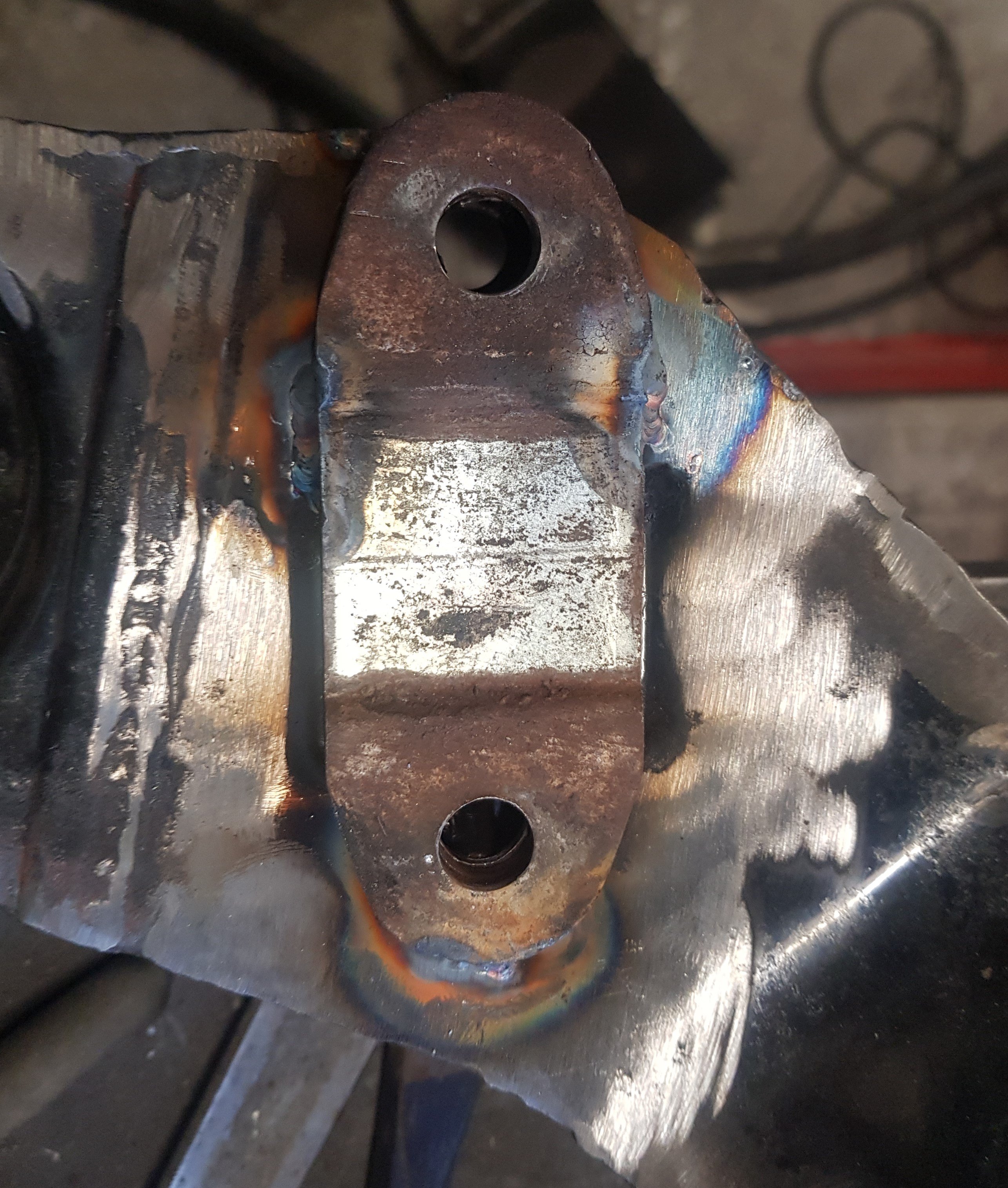
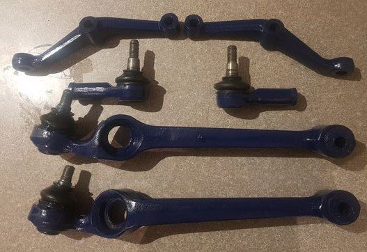
Steering column is the original TR7 column and mount, but modified to give up/down adjustment (not that it will ever be adjusted once it's set). Front suspension and steering joints have been checked, cleaned, painted and treated to new rubber boots: In fact there is a lot of freshly painted components sitting in boxes and on shelves waiting for the final assembly. Me too!
- 58 replies
-
- 13
-
-
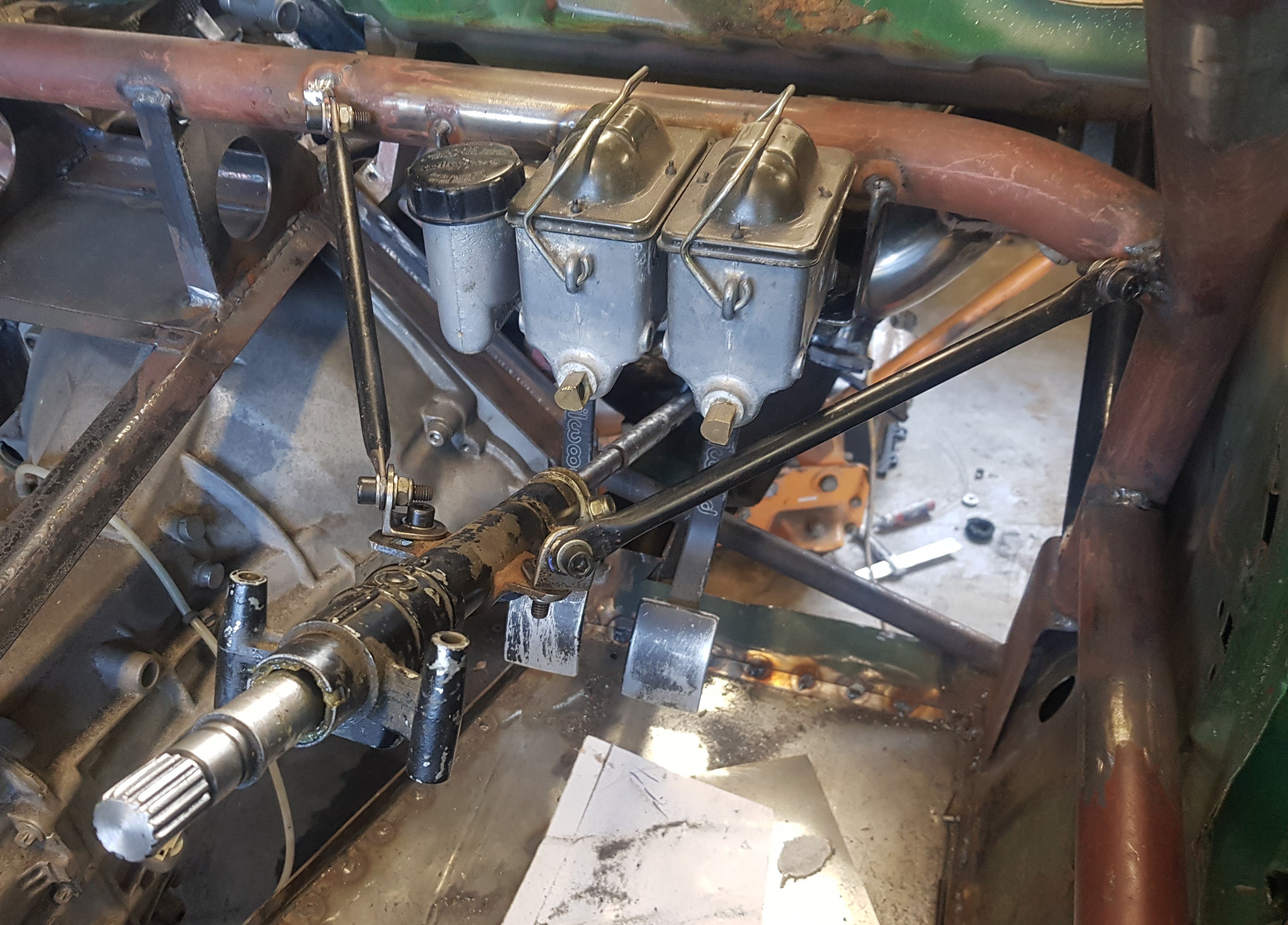
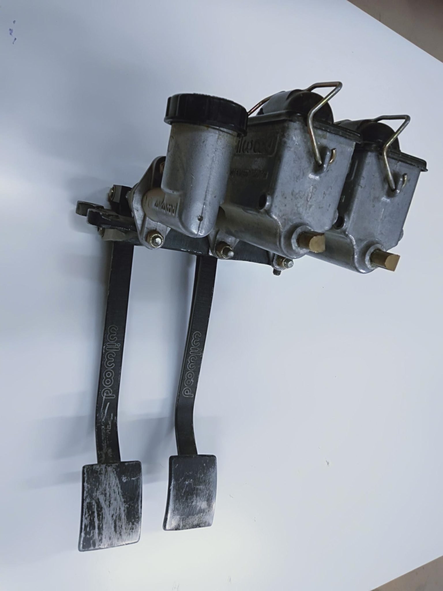
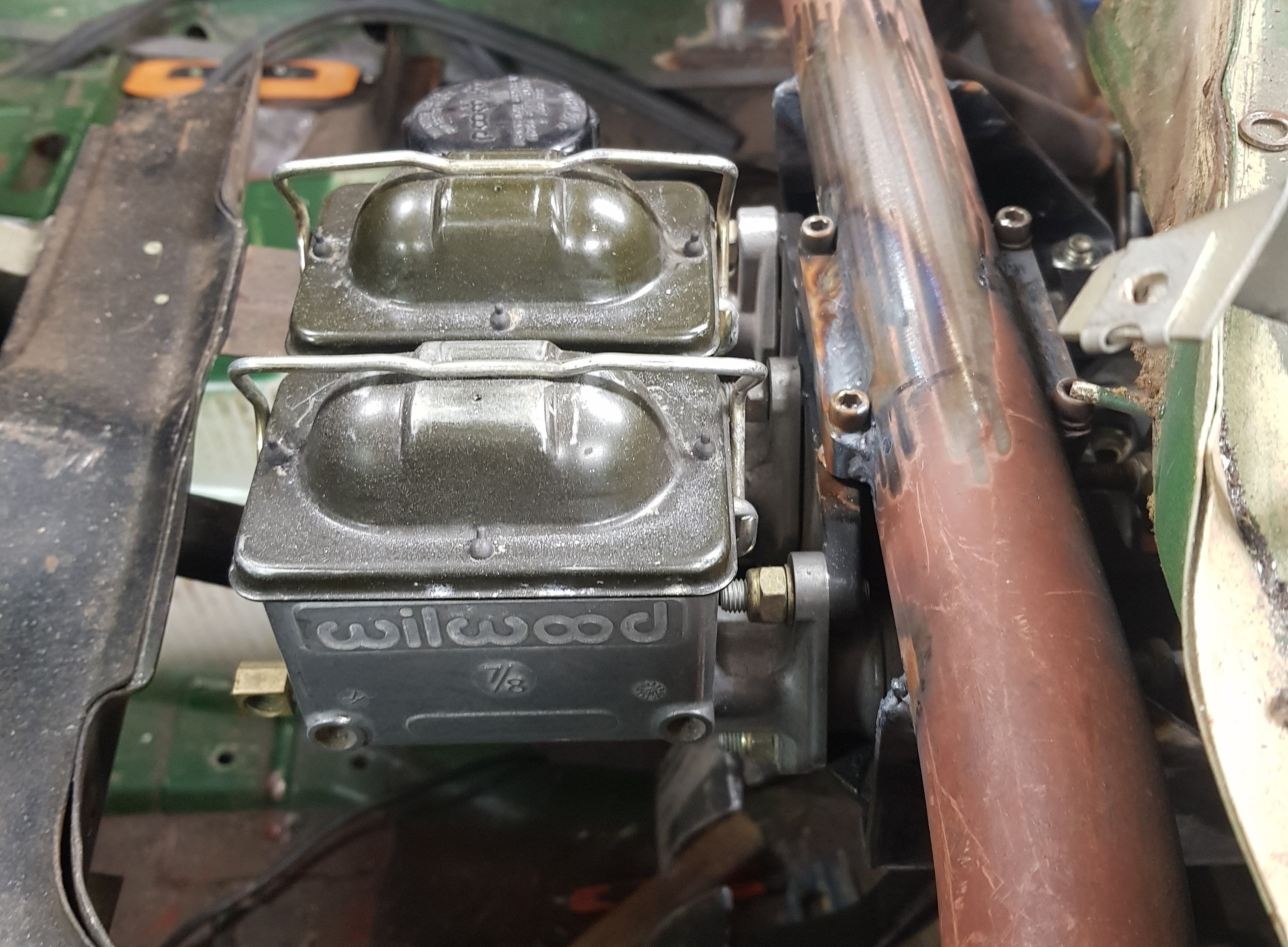
For clutch and brake I was lucky enough to score this Wilwood pedal assembly cheap: This attached to the dashboard bar of the rollcage: Held in by 4 x 1/4" UNC bolts at the top and 2 x M8 bolts at either side.
-
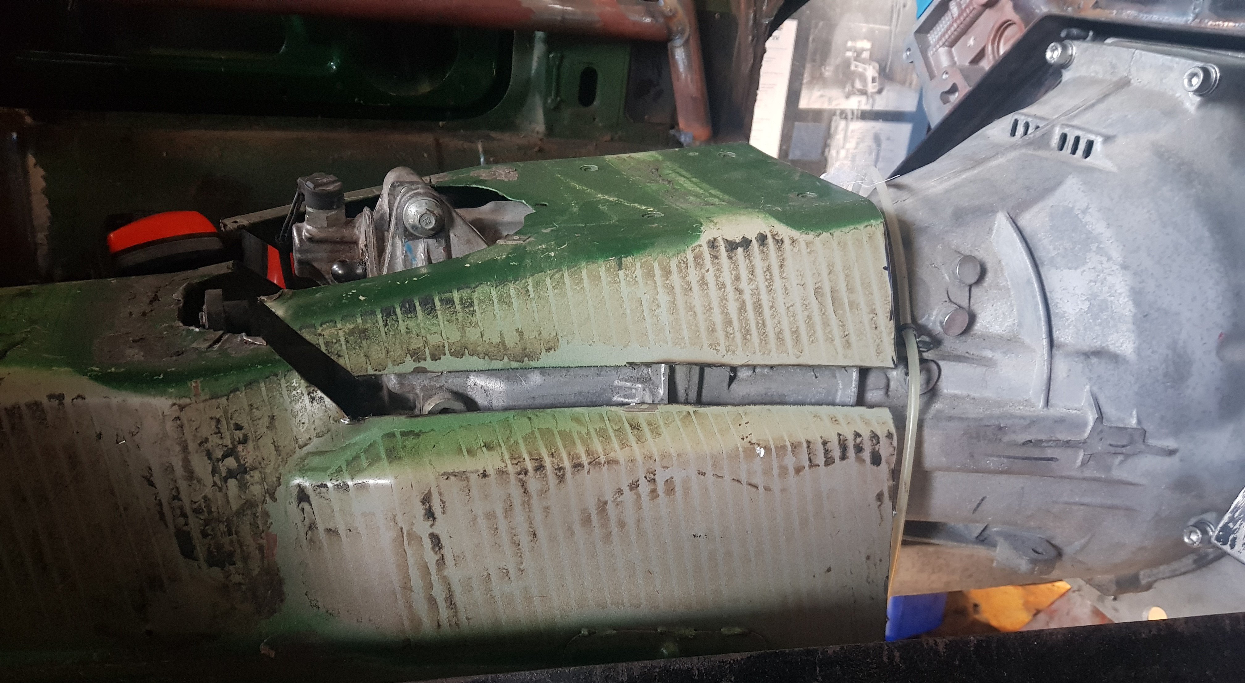
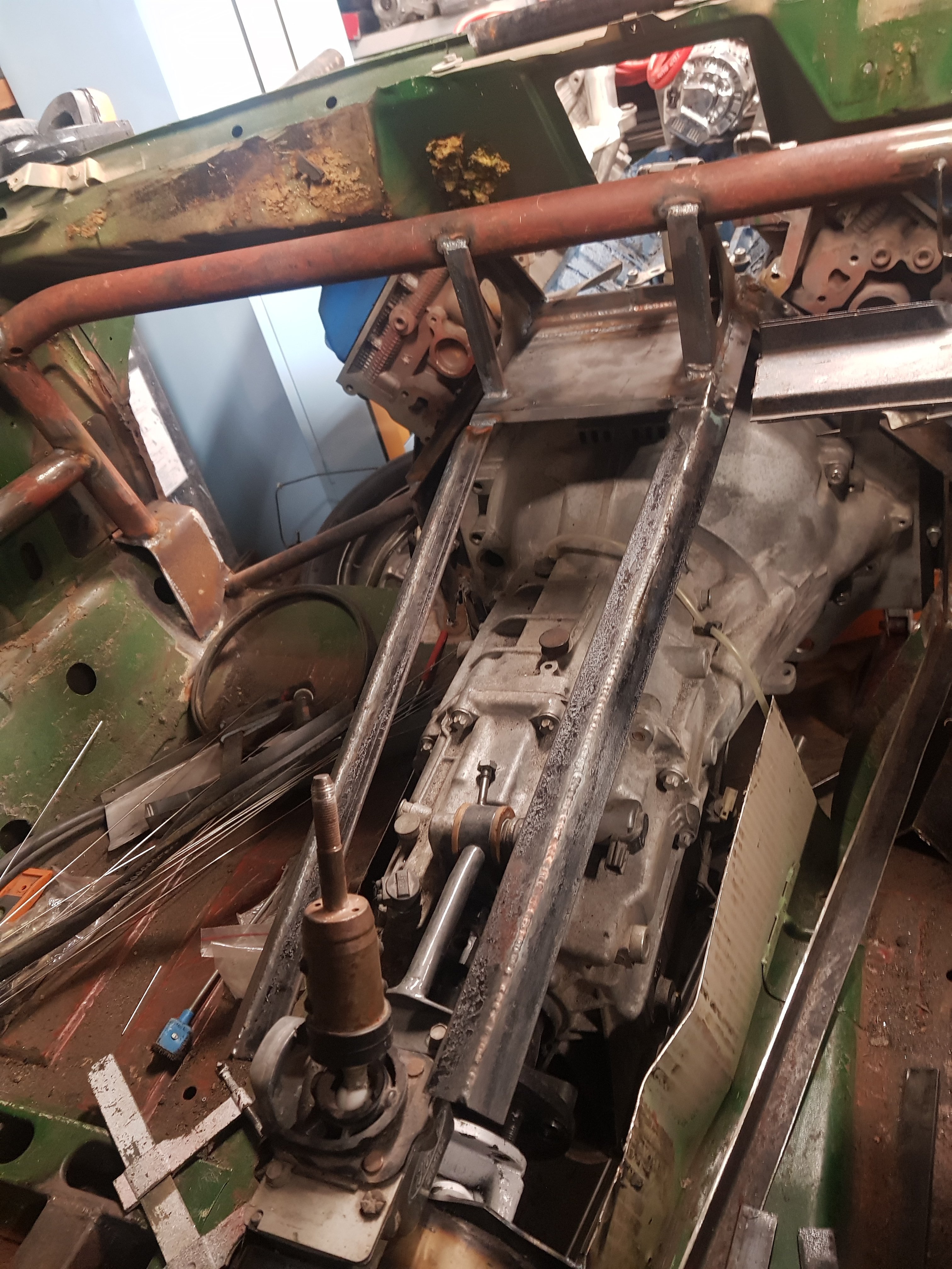
The transmission is a Getrag 6-speed from a 2012 Mustang, and it was slightly too big for the transmission tunnel: So I've put in a steel framework, this will be covered in removable aluminium panels to enable easy access:
-
Power-wise we're looking at a conservative 700bhp, with enough scope to go more but I want to keep it reliable and (wherever possible) maintenance free. It will be drag only, but does have plates so if, accidentally of course, it should fall onto the road it won't look too out of place. Except for the bonnet bulge, 12" wide drag radials, pro stock rear wing and parachute......
-
Carbs are 650 mechanical secondary (not DP) The power valve drillings have been opened up, obviously larger pump and main jets. New Viton needle valves and a few other bits I can't remember!
-
Some nice reactions in the build section. Let's have your comments!
-
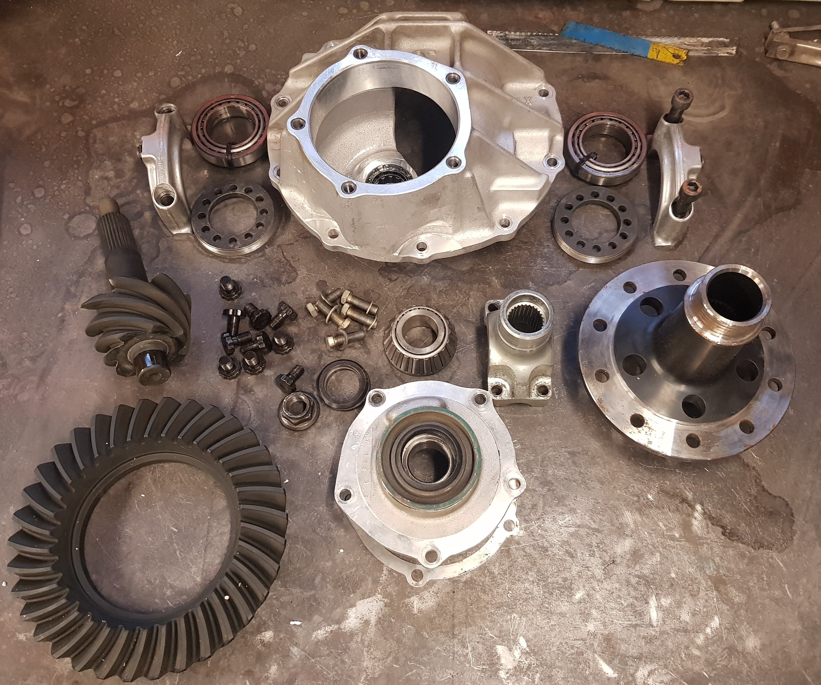
And it's about time I emptied a few boxes of stuff: And bolted it all together: Specs are: Strange alloy casing, Strange 35 spline spool, Richmond 4.8:1 gears. ARP bolts. Decent bearings!
- 58 replies
-
- 16
-