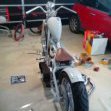
Kimjon Posted September 23, 2018 Share Posted September 23, 2018 When you make a few things over the years...no doubt you'll end up with a few boxes of shit you don't need, but is too good to throw out. I was rummaging through these said boxes and found a few interesting bits that started taking shape on my workbench today. This motor came with a pocket bike. I got the original motor going so never used this spare one. I had a pumper carburetor lying around from when I made the goped Bigfoot with the highly ported 49cc motor last year...so on it goes. This goped was purchased for parts last year. It's a geo-ped which was a stupid idea (eco friendly) goped made to comply with Californian air emissions regulations...dumb! I figure the tiny amount of time I'll spend on it, putting a much bigger motor won't make an ounce of difference to the environment...but it will be way more fun and twice the power! Obviously the motor won't just bolt on been twice the size. Geo-ped were about 23cc from memory...this will be 49cc. I cut a bit of the deck out to clear the carburetor (will tidy up later). Looks like I can make it fit. And mocked up for inspiration. Looks like it's worth pursuing this idea further:) So I'll give it some absorption time to think over some ideas...then make this shit happen! 8 Quote Link to comment Share on other sites More sharing options...
Muncie Posted September 24, 2018 Share Posted September 24, 2018 You going to run it direct drive to the tyre or use a centrifugal clutch? I really need to build something 2 stroke as they seem to work a treat on your projects. 1 1 Quote Link to comment Share on other sites More sharing options...
Kimjon Posted September 24, 2018 Author Share Posted September 24, 2018 I'm thinking direct drive. But clutches rock and make things better. I'll be doing "homework" tonight on some concepts to explore. 1 Quote Link to comment Share on other sites More sharing options...
Kimjon Posted October 4, 2018 Author Share Posted October 4, 2018 Picked up some aluminium scrap. I struggle to get materials some days...but got lucky. Turned it into this adapter plate. There's method to the madness of all those holes. Each has a purpose and a special way of going together. Then I notched the deck some more. I needed even more clearance around the carburetor. Engine mounted on adapter plate. It will be direct drive via a friction drive (spindle). I'll make the spindle later on the lathe...but for now I can carry on as I know this part will work as all my measurements are based off a centred datum. This pile of bits gave me an exhaust. I started with a KTM 300cc 2-stroke expansion chamber...and just started cutting...and cutting...and cutting... And that's it for the morning. Remainder of the day is for relaxing now:) 3 Quote Link to comment Share on other sites More sharing options...
Kimjon Posted October 5, 2018 Author Share Posted October 5, 2018 Fuck it...I'll rest when I'm dead! This will definitely work. But I'm now considering a variation on this with a longer spindle that is supported by a bearing. This isn't a new idea...been done many times before by others. The drawback of the bearing is its a parasitic loss...ie the bearing will rob power from the little motor. The positive side is it may save the crankshaft from braking! I've smashed a crankshaft before...so I'm always a little gun shy with these. So yeah/nah....let's do this again...but better. 3 Quote Link to comment Share on other sites More sharing options...
Kimjon Posted October 7, 2018 Author Share Posted October 7, 2018 Expansion chamber done. This was tricky, welding such thin and contaminated steel. One moment you'd be welding like a Jedi master...next a huge hole would blow through! Then it's the fill the hole game again... 1 Quote Link to comment Share on other sites More sharing options...
tortron Posted October 7, 2018 Share Posted October 7, 2018 2 Quote Link to comment Share on other sites More sharing options...
Kimjon Posted October 11, 2018 Author Share Posted October 11, 2018 I thought the colon needed to be wrapped. Not for performance...more for not wanting to burn my fucking leg on it, if by chance I touched it. And installed for a cheeky look Next I'll make a supportive bracket to, ummm, well, ummm...support it? 2 Quote Link to comment Share on other sites More sharing options...
KP_wag Posted October 11, 2018 Share Posted October 11, 2018 Looks choice, hopefully will give some ring ting to it 1 Quote Link to comment Share on other sites More sharing options...
MightyJoe Posted October 11, 2018 Share Posted October 11, 2018 You could go full barry and build a trailer for it and attachments. Ride to a job, remove motor to power your weed wacker, chainsaw and mower. Do the work then fit the motor back onto scooter and ring ding ding ding home again. 1 1 Quote Link to comment Share on other sites More sharing options...
Kimjon Posted October 11, 2018 Author Share Posted October 11, 2018 41 minutes ago, KP_wag said: Looks choice, hopefully will give some ring ting to it Thanks. I geeked out online searching the pros and cons of wrapping an expansion chamber. Pros: basically none. Only benefit for me is avoiding 3rd degree burns. Cons: keeps heat in, will cause premature rusting. Has potential to change the pulse wave adversely due to extra heat. Then I found someone online who's experimented with a dyno. His conclusion was as long as the first few inches on the header straight out of the motor weren't wrapped. It didn't really change things all that much...so do it if you want too. Using my usual way of Internet researching, as soon as I found someone offering the answer I wanted...I stopped looking. It's got to be true;) Quote Link to comment Share on other sites More sharing options...
KP_wag Posted October 12, 2018 Share Posted October 12, 2018 Awesome if that exhaust somehow gave this thing ridic peaky MX powerband powers. Would make an sweet city commuter, KX80 lightswitch action up the footpath ring ting BARRRRP-P-P 1 Quote Link to comment Share on other sites More sharing options...
Kimjon Posted October 13, 2018 Author Share Posted October 13, 2018 Righto...this shits getting real! I re-made the drive spindle. Using some basic maths I was able to figure out the taper angles and grind a "one off tool" to bore the hole. I then chased this up with a boring bar to get it bang on. For those who have never seen a knurling tool in action...Here's a quick video: Spindle mounted to the motor. Next up was to sort out the brackets for the expansion chamber support. That's all squared away now. Up next I mounted the motor and used loctite on all the fixings to keep them in place. The observant among you will also notice it now has a rear wheel. I stole this off my next project (the white goped). Kill switch and controls where some easy wins: I basically copied what the old goped used to have. By drilling and tapping a hole on the handlebars and fitting a kill switch. And the controls where left over bike parts modified to work. The gas tanks for these are extremely expensive! Like $50...plus postage from the USA. So I brought this tank off ebay for about $5 delivered to my door. The carburetor I'm using is a diaphragm type, or pumper as commonly called. They pump their own fuel and require two fuel lines. A feed line and a return line. So: Easy fix. Cut off the one outlet...drill it bigger. Make another hole beside it. Tap holes in 1/8" NPT. mix up some permaseal fuel resistant epoxy...bung it all together. And that's a days work done! 4 Quote Link to comment Share on other sites More sharing options...
Kimjon Posted October 14, 2018 Author Share Posted October 14, 2018 Fuel tank mounting was the order of the day. Im a sucker for milti purpose brackets...way to much time spent watching "project binky" on youtube. Anyway this is my solution to two problems. 1) hold the gas tank 2) cover an ugly hole left where the original motor was mounted. These things literally grind on the tyres. ..making lots of fine rubber dust that goes everywhere if given a chance. So blocking this hole was a essential. Here's that big hole on top. And hole blocked...plus strong bracket mounting for tank. And that basically completes it. Quote Link to comment Share on other sites More sharing options...
Kimjon Posted October 14, 2018 Author Share Posted October 14, 2018 I added a cam locking device to the axle. Basically it supports the axle and prevents it from moving under the weight of the rider and braking the crankshaft. It's the purple thing. I drilled a hole and put a pin in it. The purple thing (called an EPW..."engine protection wheel") is then pushed around until it locks in an appropriate tooth on the wheel. 1 Quote Link to comment Share on other sites More sharing options...
Popular Post Kimjon Posted October 14, 2018 Author Popular Post Share Posted October 14, 2018 Yes...yes it is! Finished. 49cc of stupidly fast goped!!! It's slipping on the wheel a bit, as the wheel is worn-out and has become egg shaped. However that is genuine wheel spinning power your witnessing in that youtube clip. Seriously when in powerband it spins the rear wheel! Yeah buddy...it rips!!! Wheel spinning goodness. This hard tyre goped is awesome! Back to basics motorised fun! 10 Quote Link to comment Share on other sites More sharing options...
KP_wag Posted October 14, 2018 Share Posted October 14, 2018 Hilarious, is it super loud? Quote Link to comment Share on other sites More sharing options...
Kimjon Posted October 14, 2018 Author Share Posted October 14, 2018 1 hour ago, KP_wag said: Hilarious, is it super loud? Yip! Sure is. It's not quite in tune yet, and I want to experiment with closing the hole down a bit on the pipes exit, as I think I'll make more back pressure and that could be beneficial? Here it is parked up with some of the fleet;) Sad thing is there's many more to come... 3 Quote Link to comment Share on other sites More sharing options...
Truenotch Posted October 16, 2018 Share Posted October 16, 2018 Yep, close that bleed hole up! I’m picking for 49cc you’ll want 14-15mm at the exit. It looks pretty huge at the mo? Smaller exit = more of the pressure wave returned off the reversion cone = more likely to achieve e resonance. Great work once again. You must have set a record for most projects finished on oldscool! 1 1 Quote Link to comment Share on other sites More sharing options...
Raizer Posted October 16, 2018 Share Posted October 16, 2018 Dragged this thing home among a few trailer loads of scooters a while back, any use to you for parts or something? 1 1 Quote Link to comment Share on other sites More sharing options...

Recommended Posts
Join the conversation
You can post now and register later. If you have an account, sign in now to post with your account.