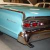
Popular Post Nominal Posted May 8, 2014 Popular Post Share Posted May 8, 2014 OK, so since I am actually doing something with this right now I guess I should get a project thread going. Discussion: //oldschool.co.nz/index.php?/topic/43506-nominals-1964-mercury/ We've had this car since 2003. At the time I was working in Indianapolis for a few months, and looking for another car to bring home (at the time I also had a '69 Lincoln in NZ). I did a lot of looking online, but only inspected a couple of cars. The first was a "rust free" late 60's Galaxie, which was a bit too rusty. The second was this one. Something about the colour and chrome combination was very attractive. As bought, it had been on fire, with the air cleaner burnt up, and a large burn mark in the centre of the bonnet. The PO told me it had backfired through the carb, setting fire to the filter. He had got it running again with a cleaned up (or replacement?) carb. It would only drive in 1st and 2nd gears though. After a quick test drive we decided it was too cool to pass on so bought it. We were still in Indianapolis for a couple of months more so brought it back to the apartment complex and parked it in one of the garages. Like most US accommodation there were many rules in place, including some banning working on cars on-site (seriously). Managed to get the gearbox shifting by fixing the vacuum line routing. Also took the hood off to get it repainted. Otherwise I just used it locally and to/from work when the weather was nice. Outside office with stepdaughter (who now has a 2yo child sheesh) and missus. Engine as bought. 390ci Ford FE which is stock AFAIK. 2 barrel carb for economy (ha ha). When we were due to come home the car went on an open transporter to LA, then into a container via Steve Curle. It arrived in NZ a few weeks later and after coughing up the $$$ to officialdom came home. It had survived the trip fairly well, only getting dirty. The gas tank was hanging out (I suppose they drained it at some stage) and one tank strap had gone awol. While the tank was out I repaired some rust in the body mount in the trunk. Some genius has filled it with epoxy. After fixing that, fitting a high-level stop light, and swapping the low beam lights for some that dipped to the left it passed the VTNZ check to be road legal. 15 Quote Link to comment Share on other sites More sharing options...
Popular Post Nominal Posted May 10, 2014 Author Popular Post Share Posted May 10, 2014 The black carpet was faded to brown (peril of a convertible) so I work contact kindly carried a new carpet as baggage to NZ. Removing the interior revealed a mostly good floor (the car was sold new in Illinois so that is an achievement) with a little rust that was dealt to. The surface was was cleaned up and neutralised, then POR15 applied. The roof mechanism is operated by this hydraulic pump behind the back seat. At the same time as the new carpet I fitted a more modern sound system with a sub mounted in a closed off area (big MDF panel) behind this seat, amp in trunk, head unit under front seat, and some 5" speakers up under the dash. All TM specials - sounds OK, nothing brilliant, but better than AM when on the road. Acquired some Astro - style- wheels at the PN swap meet, and bought new thin stripe whitewalls. For the sky-scraper look. Plus, these whitewalls were a right bitch to keep white. 10 Quote Link to comment Share on other sites More sharing options...
Nominal Posted May 21, 2014 Author Share Posted May 21, 2014 After a year or so one of the Astro wheels had an 'issue' which resulted in their removal from the car. I went back to the original 14" steels for a while, but needed something better for the Beach Hop, so acquired some 14" 5 spokes via Trademe. After a clean up, paint, and some newly spun bullets... Have done a couple of weddings. These are usually somewhat fun, but involve a lot of waiting around. At least this time I had a hooker in a Lincoln to chat with. 1 Quote Link to comment Share on other sites More sharing options...
Nominal Posted June 2, 2014 Author Share Posted June 2, 2014 The original grille is a stamped aluminium affair with vertical bars. The design is fussy, and the blacked out areas really needed repainting. I don't have a good before pic, but this one shows the grille reasonably well. A complicating factor is the quad headlights. I designed the grille to use the existing headlight surrounds. This means that the new bars follow the same V profile as the original, both vertically and horizontally The first step was removing the headlights and original grille. A workshop manual was handy as there are quite a few bolts involved. I had to paint the area behind the headlights satin black as it was previously body coloured. I got rid of the dead moths later! Each dual headlight assemble is a large pot-metal casting that bolts through the radiator support in 4 places. The tube grille assembly between the headlights would need to be attached to this casting. After checking out some tubing sizes and looks I settled on a 7-bar design using 5/8" (16mm) stainless steel tubing. I made some plywood mounting brackets to test out the look. When correctly assembled the headlight bezels cover the ends of the tubing. After sourcing some tubing and cutting to the correct lengths (the usual measure twice, cut once routine) I made a template (with the small holes) then used this to create a couple of mounting plates from some stainless steel sheet. The larger holes were drilled with a unibit. Most of the holes where then cut off with a Bosch shear to leave this shape. The small cutouts were a bit help in locating and aligning the tubing. For these short pieces I also used the plywood brackets for alignment when welding. The tubes were MIG welded to the mounts. I didn't have an SS wire handy so just used the normal steel MIG setup - hopefully this won't bite me in the ass later. Due to the stepping spacing of the headlights (that matches the overall V at the front of this Mercury) the mounts are not at 90 degrees to the tubing. I didn't really want to drill the headlight mount casting, but didn';t see a good option. So I made these large mounting plates which bolt to the casting in four places. Trial assembly. Both between-headlight assemblies with the mounting brackets and plates painted black. Looking OK! 4 Quote Link to comment Share on other sites More sharing options...
Popular Post Nominal Posted June 2, 2014 Author Popular Post Share Posted June 2, 2014 Now for the main part of the grille. I had a friend (Hi Shane) cut the main bars and tig weld them together at the correct angle. I hand filed the welds then finished the joins with various grades of emery tape and a quick session with a buffer. Partially assembled here with some of the plywood mounts to see if it was all going to work. I started the assembly with the shortest (middle) bar and some more mounting brackets Adding bars. The shaped brackets made it really easy to assemble straight. It would have been a real pain to get in alignment any other way. Once fully assembled I blocked the bars up in the grille opening and made some body mounts to span between the existing radiator support structure (or hood latch in this case) and the triangular brackets. This worked well, and made it easy to assemble the grille first. Remember to check at each stage that the grille can be removed from the car without too much dismantling, and that all the mounting bolts can be reached with a socket or spanner. Cutting out some more stainless for the body mounts. This shear made life easy! Once all together I painted all the bracketry (and welds on the backside of the tubes) with a spray bomb. Overspray on the tubing was removed with thinners before it dried. The finished product. I am really pleased how this turned out. It cleans up the front of the car no end. Since this pic we';ve been on a long drive to the Whangamata Beach Hop. No problems with the grille except a fair few bugs stuck on it! (this was done back in 2013) 20 Quote Link to comment Share on other sites More sharing options...
Nominal Posted July 24, 2014 Author Share Posted July 24, 2014 Had 3 boxes to pick up at Mainfreight today. Much exite. Also, acquired some heat for the shed for those cool winter nights. 3 Quote Link to comment Share on other sites More sharing options...
Nominal Posted August 27, 2014 Author Share Posted August 27, 2014 Wish I could find the box with the nuts and centres in right now. Lost in the shed somewhere. Anyway, back in 1963 Ford introduced the 'compliance link' into the front suspension of the Galaxie (and fullsize Mercury). This is a offset pivot on the front of the lower A-arm that allows the arm to move back under compression (or something like that). It was such a 'great' idea that it was dropped after the 1964 year. When driving the car with these things it gives a weird feel to the front suspension, especially under braking. While still in the USA a bought a big steel bar that bolts between the links on each side and effectively locks them out. Worked fine, but now that I am doing the airbag thing, I wanted to get rid of it. Here is the link in the chassis after the A-arm was removed. Here are the parts out the chassis. The shaft threads inside the housing which is in turn threaded into the chassis. I had to borrow a big 3/4 drive socket from oldschooler CXGPWR to get it out. There are various kits available (at outrageous prices) to replace this. Some use a straight bolt mounted through the centre of the housing, while others have new offset mounts in the chassis. I decided to use the offset approach as it puts the pivot in the factory 'rest' location. A chunk of 50mm bar got mounted in the 4-jaw of my old clunker lathe to start the process. Here is the result. The thinner mount goes in front, the thicker towards the rear. It needs to be thicker to take up the space used by the crank piece and a washer thingy. The through bolt is 3/4 x 9 inches (thanks NZFord for supplying those). They seem to work fine in the chassis. When I'm done tinkering I'll tack them to the crossmember so they don't rotate. 1 Quote Link to comment Share on other sites More sharing options...
Nominal Posted October 27, 2014 Author Share Posted October 27, 2014 Making some progress with the bag setup. When I bought the car it had been fitted with an A/C dash (it wasn't A/C originally) and was supplied with a York compressor and some of the mounts. First problem was the crank pulley. It was running two sheaves on the crank, one for the water pump and alternator, and one for the power steering. The factory setup has a third sheave for the A/C, running around an adjustable idler. I was visiting the US back in September so managed to order the correct pulley (which fits over the balance, so was huge) and A/C mounting bracket. Unfortunately the seller didn't do a very good packaging job with only the crank pulley arriving. I managed to get another A/C mount via Craigslist at short notice though, so it worked out OK. When I got home I realised that I needed a smaller water pump pulley to fit with the big crank pulley. Not having a good source for this I cut the inner sheave off my newly acquired pulley and mounted it to the old skinny balancer. For some reason this didn't align with the P/S pump. so a 3mm spacer was needed between the pulleys. New pulley mounted up This is the newer of the two A/C compressors. It's a York 2-piston unit. I tested the magnetic clutch and that the unit still spun OK. This is the idler for the A/C belt which also includes the alternator mount and adjuster. I had to cut off one ear to fit around the water pump, and also adjust some spacing for belt alignment. The 50 year old A/C mount needed some clean up and rust removal in acid. Nasty stuff! The mounting bits almost ready to go on. I wanted to block off an oil passage which allows crank case oil to be sucked into the compressor suction side. This doesn't matter in a closed A/C system, but is messy when using it as an air compressor. Head off shows the reed-type valves. Removing the valve plate shows the pistons. The crank is in a separate chamber below. I used a self-tapping screw to block the passage. All assembled onto the engine, and with a couple of new belts as the lengths had changed. I started the car up and it all stayed in place. Jumping the magnetic clutch resulted in some satisfying pumping action. 3 Quote Link to comment Share on other sites More sharing options...
Nominal Posted December 7, 2014 Author Share Posted December 7, 2014 OK, so the front end is progressing OK. Lower A-arms are off getting tig welded (needed for cert) and I should get them back tomorrow. Where should I go for crack testing in Wellington? Have acquired some Falcon front discs which look promising to use on the Merc stubs (the Falcon discs are integral with the hub). Pulled the stock single-pot MC off and it looks like the mid-70's US Ford dual M/C will work fine. Pics of all this to come. Current problem is getting the leaf springs off. The pic shows the front mounting to the chassis. There is a big shouldered bolt that runs through the spring bushing, then bolts to the outer side of the chassis rail. There is an access hole to the nut inside the chassis rail.... and through the big X-crossmember too. However the thread and nut look well rusted (probably haven't been removed for 50 years), so getting it apart will be a challenge. I think I'm going to need a grinder with a cutting disc. 2 Quote Link to comment Share on other sites More sharing options...
Nominal Posted December 9, 2014 Author Share Posted December 9, 2014 OK, so front suspension progress. Dirty old stock system I made a spring compressor from some threaded rod. and a couple of steel plates/tubes Dealing with loaded springs makes me nervous, so I didn't want to leave any way for it to escape. It's a beefy spring, weighs about 10kg. Static weight on front of car is right around 1000kg. Upper mounts are made from steel tubing, plates, and some threaded rod that goes through the old upper shock mount. I didn't want to have to cut/weld the chassis spring pockets while the whole car is assembled, so the top of the airbag sits just below the pocket. 2 Quote Link to comment Share on other sites More sharing options...
Nominal Posted December 9, 2014 Author Share Posted December 9, 2014 This means that the bag needs to sit down into the lower A-arm, roughly even with the bottom of the arm. Which means some cutting.... I later had to cut a lot more away from the arm for clearance to the bag sides. So, it goes together like this. I think this is roughly ride height. It's designed so that the bag ends are parallel at ride height. Should look like this.... Sorting the shocks and mounts was a hassle. Due to the way the chassis is designed I needed to have the lower shock mount located further out towards the ball joint. This means a longer shock stroke is needed. Even with the longest I could locate (something from a Valiant) I need to limit droop travel a bit, but I don't expect to be getting the front end airbourne so hope this works out OK. Inner guard needed to be cut for the upper mount. The upper mount has another piece that locates right down the depth of the chassis. It's all made from 6mm plate, so won't be going anywhere. Having one side worked out meant that the other side was quicker - just duplicate... I needed to fill in the gaps to rebuilt the A-arm strength. I used some donated 3.5mm plate for this. After chewing through a few cut-off wheels I realised I could use the Nibbler to shear this size. It did work OK, but the small pieces of plate were hard to hold on to when it was running. Here's the arms tacked together, ready to go off to the tig man. I should get them back this week. Anyone know where to go for crack testing in Wellington? Also acquired the airbag controller setup. 5 Quote Link to comment Share on other sites More sharing options...
Nominal Posted December 9, 2014 Author Share Posted December 9, 2014 At the rear, I needed to get the axle out so I can deal with the front spring mounts. The old leafs look a bit shagged..... Got it all unbolted after some persuasion with long breaker bars and a rattle gun. Having the car on a lift is great, but it is a bit tricky to remove heavy parts from under the car. After a bit of a wrestle with jack stands and trolleys there is a large hole to fill. At least I won't have to swap in a 9" - it comes with one from the factory. 5 Quote Link to comment Share on other sites More sharing options...
Nominal Posted December 18, 2014 Author Share Posted December 18, 2014 OK, so springs extracted with grinder. I don't thing that nut (the rusty thing at bottom left) was going to come undone. A package arrived from Airride NZ - I think this is the last big order. Only plumbing fittings and P clips needed now. Also picked up some 25mm Sch 80 tube for the 4-bars. Pipe sizing is weird. No dimension on this stuff is 25mm. 2 Quote Link to comment Share on other sites More sharing options...
Nominal Posted December 29, 2014 Author Share Posted December 29, 2014 That moment when you remember that the centre of a 9" housing is not the same as the centre of the pumpkin because of the pinion offset. Oh well, the bracket is only tacked on. Quote Link to comment Share on other sites More sharing options...
Nominal Posted February 15, 2015 Author Share Posted February 15, 2015 Been busy busy working on the suspension. Rear triangulated 4-link is built, airbags set up at the back. Currently all out of the car so I could weld the brackets (done now), and re-route the exhaust (partly done). Have gone back to the front end to sort some disc brakes and plumbing/wiring. BA Falcon caliper and disc. Hopefully the brakes will work OK when driven, I have a big M/C from a US ford (77 t-bird or something like that). Keeping the standard drums on the back. Only just fits inside the wheel, with a tiny bit of filing on the caliper. I cut the caliper bracket like that in case I needed to pick up the third boss on the spindle. I think it will be OK with two though, because the big 1/2" bolt on the upright part took the main load of the drum brakes. Adding the third point would mean getting more tig welding and crack testing done and I am short of time. This is tonight, one side pretty sorted. The Falcon flex hoses should work too. New upper balljoint fitted. New shocks on relocated mounts. Height sensor fitted. Have to do other side next, which needs the shock mount welded on then assembling. Then finish exhausts and reinstall diff. Finish plumbing, mount air tank, hook up some power and test it out. Hope to have it all working next week for cert prior to Beach Hop. Clipping the air lines every 300mm is a pain. Any suggestions on easy ways to mount the clips to the chassis rail? I have done with a pop rivet, but I think that is crappy. Maybe some hex headed self tappers? Drilling and tapping is difficult due to clearance issues. 4 Quote Link to comment Share on other sites More sharing options...
Nominal Posted February 23, 2015 Author Share Posted February 23, 2015 Been slaving on this the last few days and weekends. Found some suitable hex-drive self tappers are Mitre 10 (oh the shame). Bought some more airline only to realise that there are two systems - imperial 3/8, and metric 10mm, and they are not interchangeable (even though 3/8 is 9.5mm). Luckily I hadn't put much of the wrong line in place. Found that to fit the rear wheels I need to deflate the tires, and pump the bags right up - bit tricky before the system is working. I'll have to pack some fittings and an inflater in the trunk in the future - along with the deep socket for the wheel nuts. Also found that it is hard to get a jack out from under a lowered vehicle. Luckily the lift allowed me to drop it onto some jackstands. Aired out the chassis rail sits on the upright flange of the lift deck. Got it started (engine-driven compressor), and tried the auto-level cycle, but it behaved oddly. I tried manually, but couldn't control all the corners correctly. It turned out that the cable to the VU4 valve assembly wasn't fully plugged in - worked better after that, and the auto-level seemed OK. I stopped eventually as it was past midnight, and the shed was full of fumes. Next I need to sort a few minor brake issues before a test drive - Caliper brackets need re-drilling to provide a little more wheel clearance - Brake lines on diff housing need to be replace/rerouted to clear new brackets and for exhaust clearance - Bleed brakes and ROAD TEST 8 Quote Link to comment Share on other sites More sharing options...
Popular Post Nominal Posted February 26, 2015 Author Popular Post Share Posted February 26, 2015 Exited the shed last night, first time since May 2014 (I need to work faster!) First test drive went 'ok' ish, until the compressor clutch locked up and the air line blew out with a big bang Cue slow drive back home on bump stops. So, need to sort that and fit a one-way valve to the compressor line. Had a beer after that episode, and left the car outside. Washed it today, need to clean up garage then get it back in to pick up the issues. Looks cool dumped though. Before wash And after. 21 Quote Link to comment Share on other sites More sharing options...
Nominal Posted February 27, 2015 Author Share Posted February 27, 2015 Dud compressor clutch bearing extracted. Pictured (on the left) next to one I got from another compressor (with a different style clutch) I had in the shed. It seems to be a fairly common part to the york/tecumseh compressor. Have ordered a new one from Mana Bearings to pick up on Monday. Put the other old one in for now, which seems to work fine, so took another test drive, and actually made it home OK. Need to tinker with the brakes in the weekend, but it's time for a beer now. 1 Quote Link to comment Share on other sites More sharing options...
Nominal Posted March 5, 2015 Author Share Posted March 5, 2015 Backing up a bit, here's something on the rear 4-link. As I read the rules, they needed to be made from 1" schedule 80 steel tubing. This is heavy wall/high pressure tubing and is a bit difficult to get hold of in short lengths. I finally acquired some from an engineering workshop in Petone. The lower links were made to run where the front half of the leaf springs were, from a bracket welded below the leaf mount pad on the diff, to the old spring mount location on the chassis. Again according to 'the book' the through bolts on the links needed to be 5/8". I visited the Mount Shop and trolled through their catalog to find some bushes that would suit. I ended up with some leaf spring bushings for a Mitsi Canter IIRC. These needed to be trimmed for width, and custom crush tubes made up with the correct ID/OD. For the bushing outers I used some normal pipe, 1 1/2 I think. The outer fit is a little loose but will hopefully work out OK. Since I wanted to made the links adjustable, I started up threading the ID of the tube at one end. According to the book, one of the reasons for the Sch 80 tube is that the ID suits appropriate taps without machining. This is a 1"UNF tap going in. After getting the lower links done I could partially bolt the diff back in. Pinion angle slightly off here. I was doing this right before the christmas break and couldn't get any 1" UNF all-thread in time, so initially tacked one end in place to set up the mounts. This is one of the shorter upper links. For packaging reasons - I wanted to keep the upper shock mounts in the stock location to reduce the amount of work needed, it was better to have the top bars angled from the diff centre out to the chassis rails. I made some steel spacers to use for mocking up the mounts. And spent a lot of time getting familiar with the angle grinder and cut-off discs. Quote Link to comment Share on other sites More sharing options...
Popular Post Nominal Posted March 5, 2015 Author Popular Post Share Posted March 5, 2015 The chassis mounts for the upper bars are made from some square tubing I had that happened to be the correct size. I've seen this done on the net, and it makes it easy to fabricate and plenty strong. Somewhere about here should work... After the slight setback noted above, where I realised that the housing on the 9" is not centered between the wheels, I got it all together on both sides. Plenty of jacking up and down followed to check clearances, and it all looked good to me. After getting back from camping in late Jan I finally got the 1" all thread and half nuts (those nuts are expensive - $15 each. If I'd known that I would have bought regular nuts and cut them down in the lathe) so it was time to make the bars adjustable. This involved grinding off the tacks and welding the end to a short length of all-thread. Then the link is shorted up and an inspection hole drilled 1.5 diameters down the tubing. I did have to do one of these a couple of times after failed the 'measure twice cut once' test, mainly because the pinion angle was way out on my fixed length bars. One hunky adjustable triangulated 4-bar top link. Since it is for the rear suspension it can be mig welded (by me) and doesn't require crack testing. Hopefully the certifier is happy. With all the links in place I adjusted them to centre the housing in the car and square it up - just done with a tape measure to reference points on the chassis. I had the wheel alignment done yesterday, and the computer said the rear thrust angle was 0.00 degrees - i.e. the housing is exactly square in the car, so I was pretty happy with that. Hopefully the cert man (Andy Smith) is happy with the design and execution. 10 Quote Link to comment Share on other sites More sharing options...

Recommended Posts
Join the conversation
You can post now and register later. If you have an account, sign in now to post with your account.