


azzurro
-
Posts
2738 -
Joined
-
Last visited
-
Days Won
3
Posts posted by azzurro
-
-
-
@Nominal, @vivaspeed texted almost exactly the same pics
")
Mark is a GC and has plenty of other interesting vehicles including i think 2 other 2300 sedans.
Wish i had overdrive in mine!
-
 4
4
-
 1
1
-
-
- Popular Post
- Popular Post

-
21
-
- Popular Post
- Popular Post
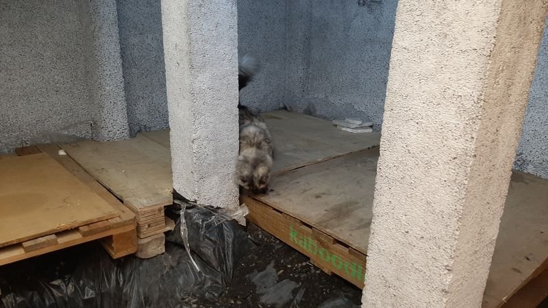
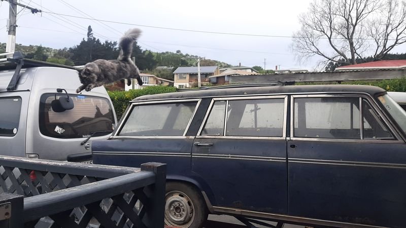
Spotted these two cream puffs in the exact same spotting spot on seperate spotting runs
the two passengers in the pickup were doggos
-
10
-
- Popular Post
- Popular Post

-
14
-
 1
1
-
Yeah, thats not 3D scanned nor did they take more than cursory look at the pattern you gave them to "copy".
Id take it all back and ask them to not have the work experience kid play with the pipe bender this time.
Close isnt good enough with that kind of part (as well they know as exhaust people), and thats not even close.
-
3
-
1
-
-
-
3
-
-
-
-
-
-
- Popular Post
- Popular Post
-
10
-
Nice!
Good work on driving onto the trailer
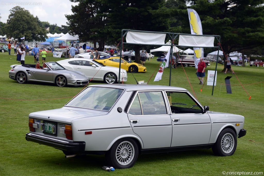
The older xx00 series Fiat stuff is noticably more solid and made with quality materials than the 12x stuff i reckon. Been impressed by the pushrod engines too!
-
- Popular Post
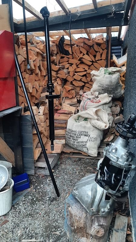
As mentioned in the show us your mancave thread, ive recently been trying to make a bit more room to shoe horn more stuff into my 'deep store'
I have some freshly levelled and inspected pallets just begging for some worthless junk to be piled upon them
The stuff in question is what remains in my storage unit in Helensville, which is mostly junk, including a 2300 wagon parts car.
Getting cleared out is loooong overdue (we moved to Dunedin nearly 4 years ago!) and the monthly is much more expensive now post covid than it was.
Im not going to do the math on how much ive spent to store this shite vs what it would have cost me to buy now off ebay with shipping from the most expensive seller if i ever needed it.
Nor will i consider the time cost of the carry on described in this post retrieving said stuff.
Anyway, plan hatched to drive my van up, surf in Kaikoura, visit the FIL in Fielding, hang with the cuzzys in Rotorua and Maketu, pick up @vivaspeed trailer in Tauranga, drive to Auckland, and over a week of also working in person in the City and visiting family and Muriwai friends, sort out and pack up the storage unit, and drag the wagon back to Dunhole, cut it up and drop the trailer back to Geoff in Oamaru. Whole think too 16 days and took me a week to get over.
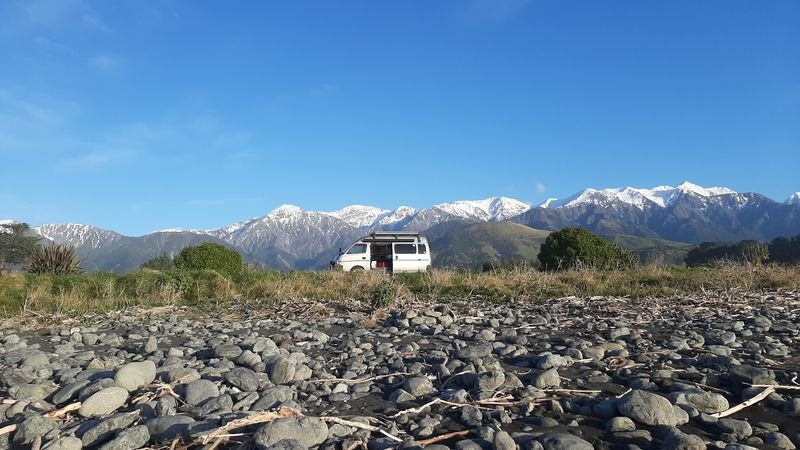
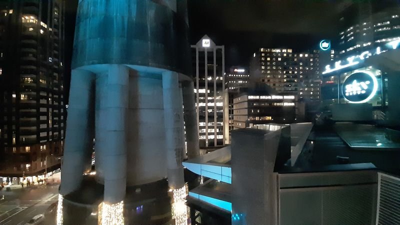
Trip up SI was nice, Dud to Kaikoura in one hit, then wake up to this
day of fun uncrowded waves at Mungamaunu before the 2am ferry
Then early morning pick up some OS freight in Welly, Fielding for a cuppa with the FIL then to Rotorua to stay with my cuz.
Maketu the next day to hang with my other cuz on the beach, then to Tauranga to pick up Geoffs trailer, made it as far as Bowentown for the night.
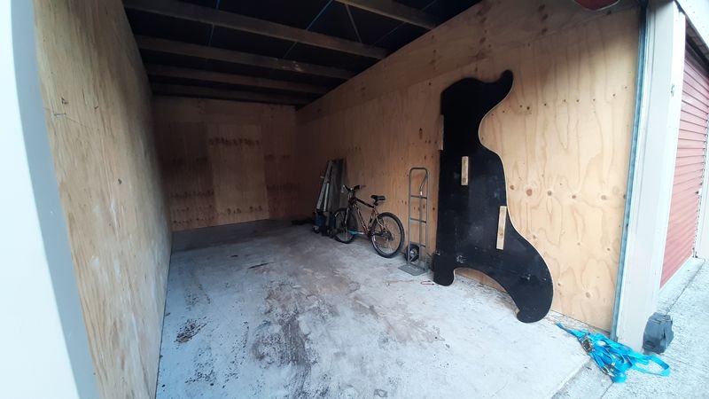
Next day thought Auckland to Helensville to drop off the trailer and have a peek into the void. Sigh.
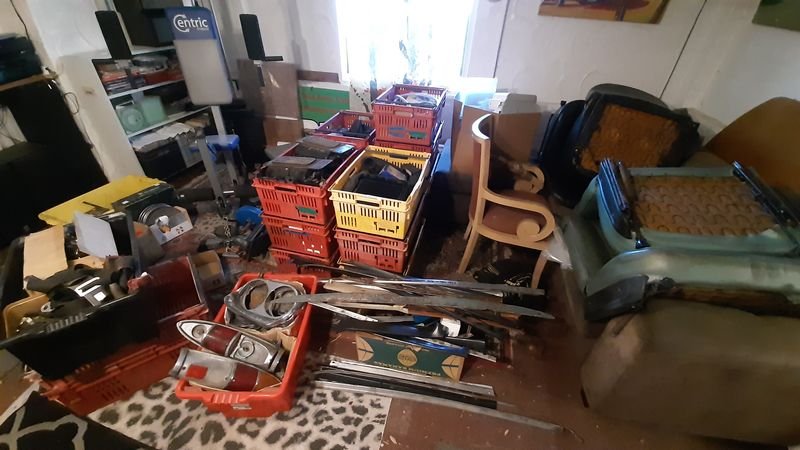
The next week was work in the city and visting. Also picked up some vege crates to stack everything into.
3 loads to the dump (the move to Dunedin happened very quickly and a lot of stuff just got thown in there, on top of the excess of rusty car parts)
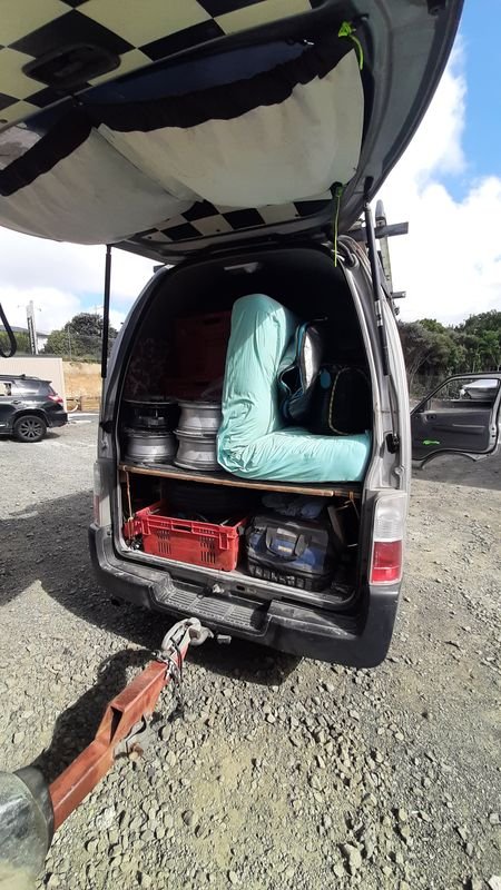
Finally on the last day it looks like this
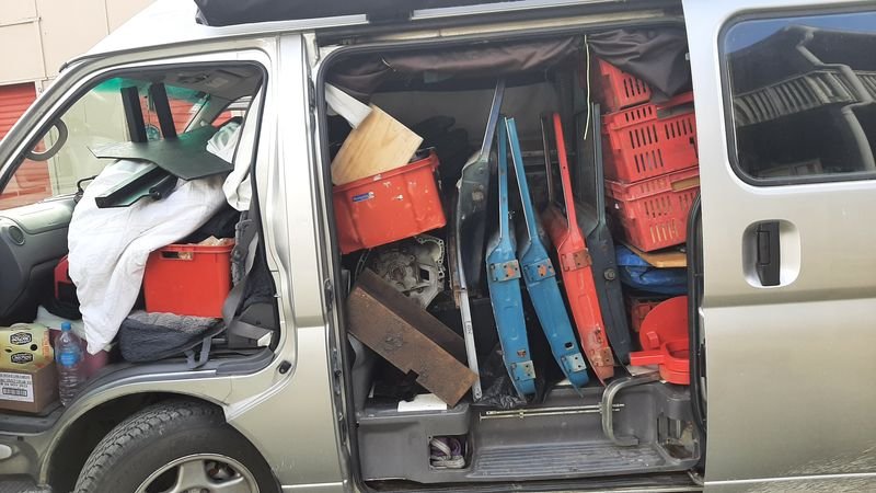
Van looks like this
Wee hidey hole int eh back - i could still sleep in there, like a frankfurter in a hotdog bun
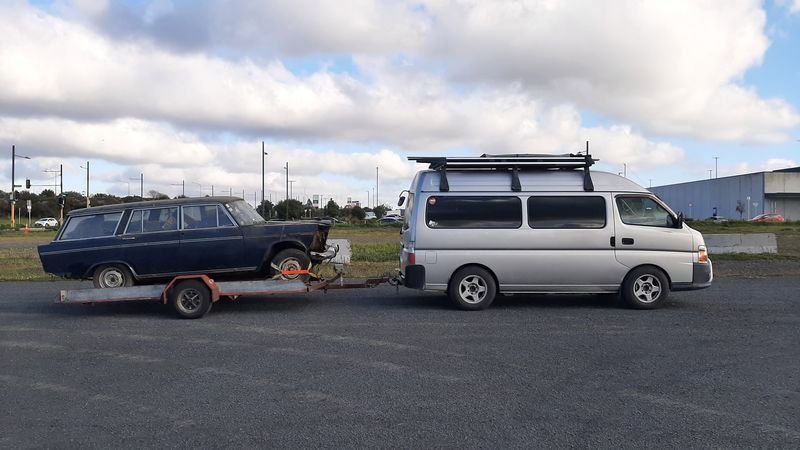
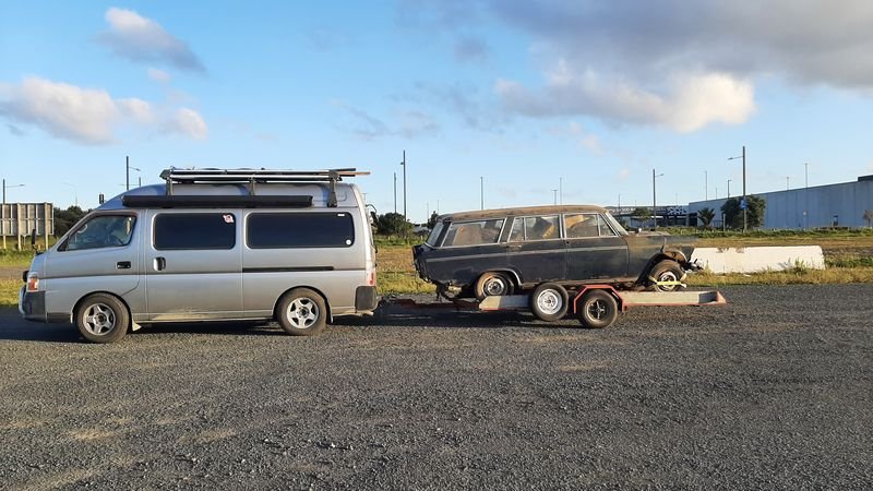
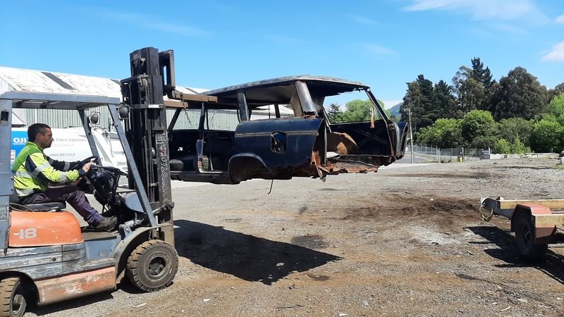
First leg fully loaded was a bit sketchy. Tail wagging the dog, despite the van having the heavy stuff (incl 2 gearboxes and 3 engines)
The main issue was the heavy end of the wagon is the wrong way round on the trailer (no engine + a load of (light) stuff in the rear), and the trailer and van tyres were underinflated as well
swapped ends at westgate and it was much better and even better after pumping all the tyres up, and when I moved the wagon back a bit in Mercer and it was even better.
No dramas after that....
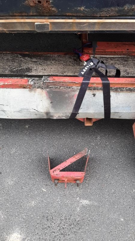
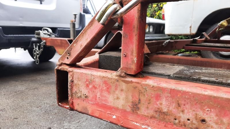
I pulled over just out of Mangaweka cause the spare on the trailer looked wobbly - i thought the wheel nuts ight have come loose, but they were tight - it was the carrier was wiggling itself off.
Strapped it up and when i got to the FILs in Fielding, ol' mate Colin from next door dug out his old stick welder (made a few hotrods with it back in the day) and blasted it back together with his safety stubbies and jandals on
7am ferry back to Picton meant on the road by 4.30am, but a cabin for a snooze on the trip over.
Home in Dunedin by 10.30pm, strait to bed!
Van went well, averaged 10.5l/100km on the way up more or less empty, 12.5l/100km on the way back, fully stacked.
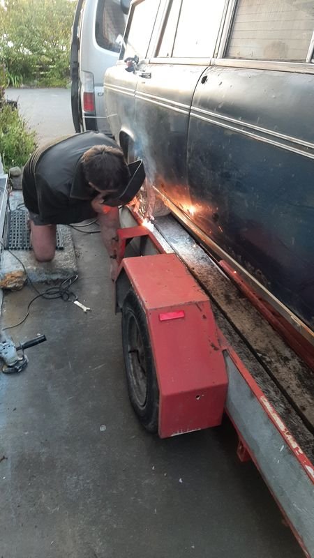
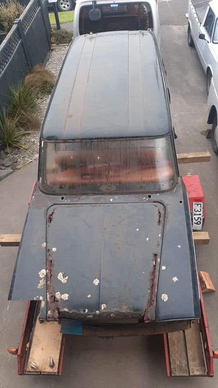
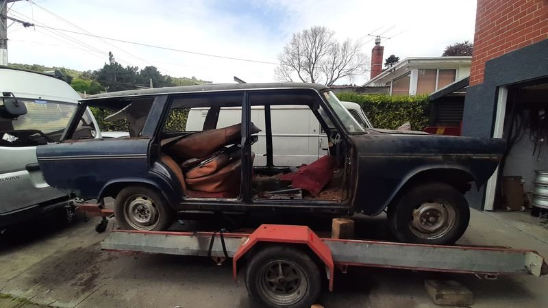
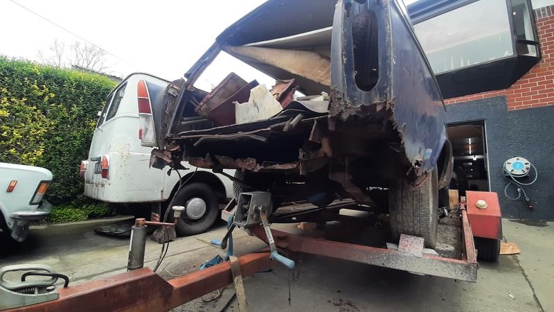
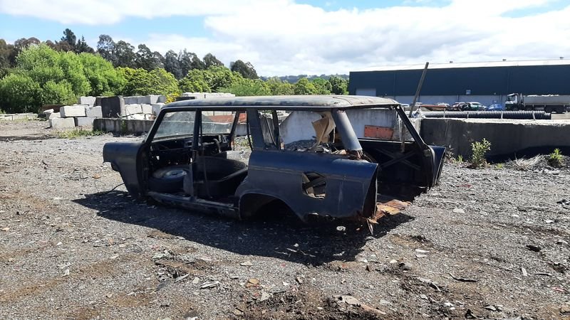
Next few days spent sorting though the stuff i collected and chopping up the wagon
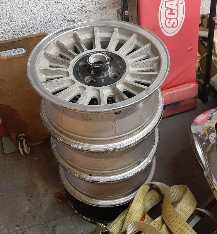
Crates of stuff, 3 sets of seats, set of rims, spare 2300 interior bits, 2300 parts, 3 engines, two gearboxes...
a set of 14x6 'MOD VIP' in 4by98 stud pattern that look sort of like a rare factory option on 131 that i might try out on the ute. Cant find out much about them but they are light and straight and 4x98, soo...
And a shitty old car to cut up
Doors off, glass out, starting to fill the car back up with stuff i wont be keeping
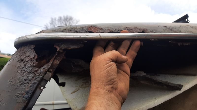
Might look ok, but shes pretty crusty up close. Unfortunately i didnt get as many rust cuts as i thought, but i did get the main bit i needed which is the front valance which will come in handy soon
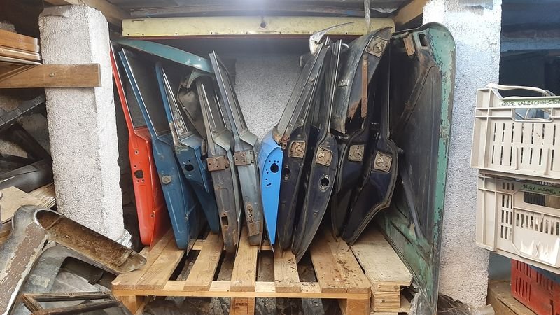
125 and 2300 panels all of which came down in this run.
Thanks to @nzstato for the borrow of the plasma cutter, much quicker and quieter the the grinder!
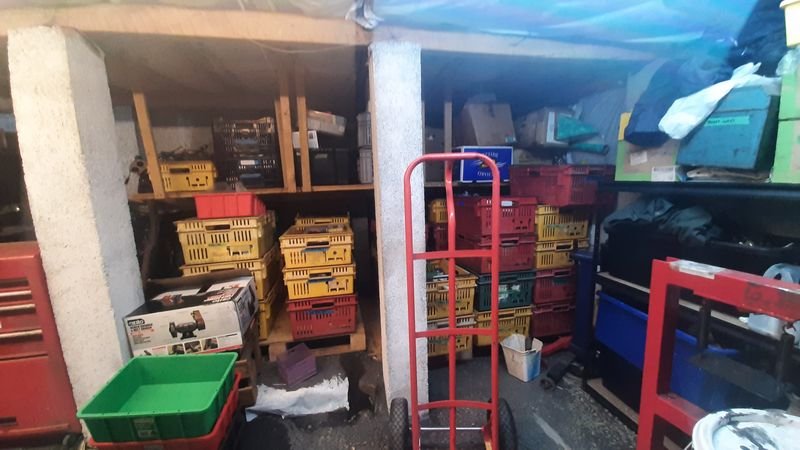
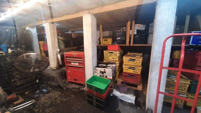
Crates stacked
And all put away. There is a bit of a system now, but more sorting to be done too.
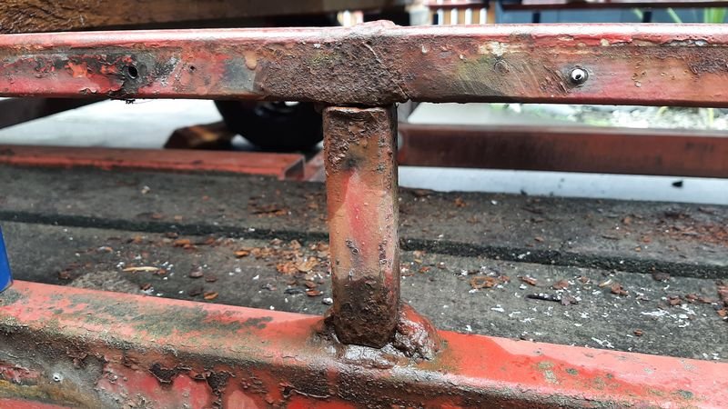
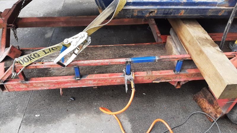
Next job, fixing up Geoffs trailer (the stick welding didnt hold and i ripped the spare mount off again in Rolleston).
I think it was a combination of being a fair bit heavier and front heavy than the race Vivas it usually carries, the effects of rust, and some less than perfect welding 40 years ago, but I wasnt going to give back a borrowed trailer in a worse state than i borrowed it!
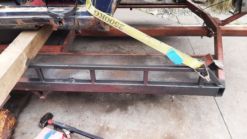
Front half much more solid now!
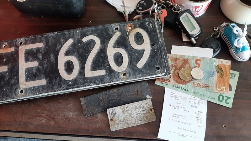
One last job for the trailer, taking $27.50 worth of 'car bodies, stripped' to the recyclers
Thanks FE 6269. last Wof was a clean sheet in 1995 at 75,765km
Anyway, thank fuck thats all done, looking forwards to not moving stuff for a good while
-
30
-
1
-
17 hours ago, Sunbeam said:
Hmmm. I don’t have a ROSA wire, and the yellow/blue connection trick doesn’t work for me. I think I must have a different alternator because the yellow wire must have a power supply or the alternator puts out 0 volts
yours is a later model than mine i think so colours may vary but basically your hooking the two pairs that go to/from the external regulator together (the two fat wires whcih are the main feed to the car fuse box, and the two skinny ones which deal with the lamp). there may also be a lamp relay under the hood which might complicate matters.
pretty sure you need to bench test the alternator with a load and a light/12v as per the setup you would have on the car or it wont output anything (the lamp is an 'exciter').
Mine is a 'single wire' which means there is only one control wire (and one main feed which isnt counted) - i think you said yours is a two wire (which i take to mean two control wires + main feed)
If its a two wire you are outside of my experience, but maybe a pic of the back of it or the labels for the pins could help figure out what what they do and how to hook it up?
-
I had a look at my 125's set up and consulted the wiring diagrams to confirm what ive done
the thin signal wires from the alternator to regulator (giallo) and regulator to IGN light (azzurro) wires are joined together - direct line from the later model (Lancia Delta ie i think? ) internally regulated alternators signal output direct to the dash light.
the thicker main supply wires from the alternator output post to regulator (grigo) and then regulator to fuse box (rosa) are* also connected together.
*i have strung a new main cable to a relay to take the load off the ignition and light switches, but yeah, basically its straight bypass of the old regulator
-
I have already clearly explained precisely what to do, in my earlier post, which I refer you to below, for your convenience
On 08/08/2023 at 08:53, azzurro said:...as simple as unplug the voltage regulator and plug a couple of those wires together, but exactly which i cant recall...
....Im probably explaining it wrong, but ....
....who is winning the Battle of the Volts...
(path of least resistance?)
...the pixies can then take the path that avoids the lamp
..How that relates to the wiring idk...
I said good day, Sir
-
4
-
-
- Popular Post
Crossing more things off the list
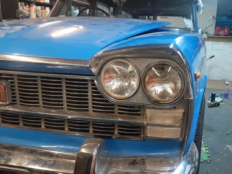
Headlights
the outer (lo and hi) headlamps had started to tarnish. They are noname/Repco ones i think.
The inner high beams are Cibie and still in good shape and are very good
The retaining rings are pretty shot tho, these ones are chromed steel, my 125p ute from 1989 in contrast has stainless ones - they are standard 5 3/4 retainers but stragly seem pretty hard to get hold of (read expensive or 'out of stock'!) , so if anyone has a good source let me know. Would like 4 but at least 2 would be good.
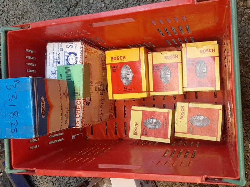
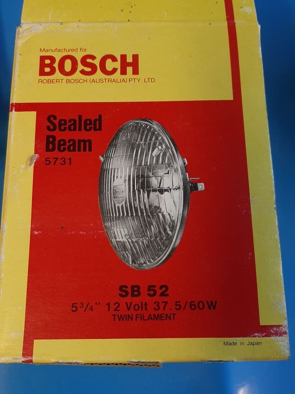
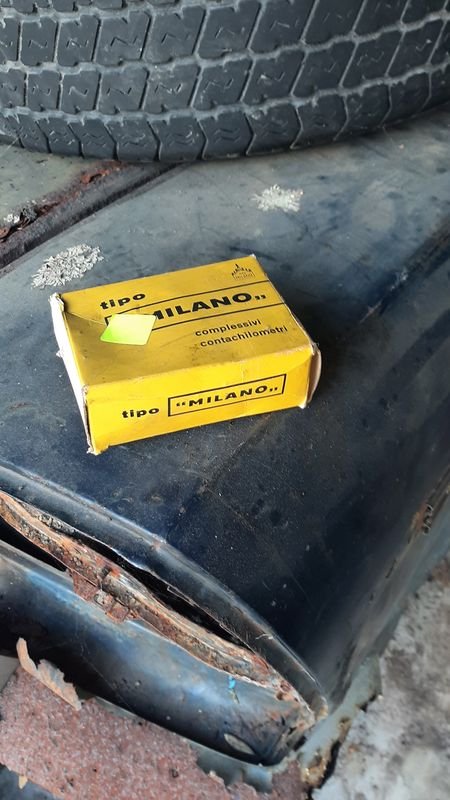
I had jumped on a wodge of 12v car electrical stuff on marketplace a while ago, mainly for the NOS Bosch bulbs, which i was holding onto for just such an occasion
Turns out they are reboxed Stanley's made in Japan, not bothered at all Stanley stuff is top notch, just pretty interesting. Pic on the box even has Stanley in the centre
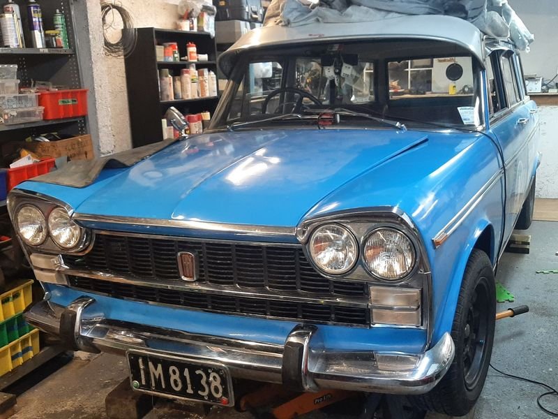
I took all the other lights off and cleaned everything up a bit including all their connections,
and swapped out the silver grille back to the black one tidied up and resprayed and the best bits from both.
Looking good sparkly eyes

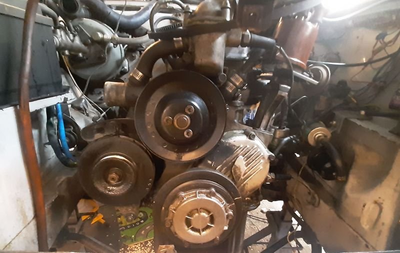
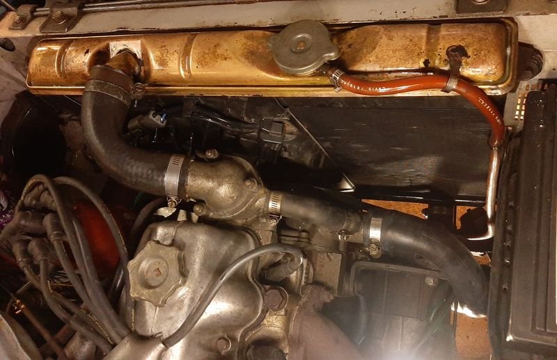
Crank Pulley and Radiator hoses
Took the radiator out to access the crankshaft pulley
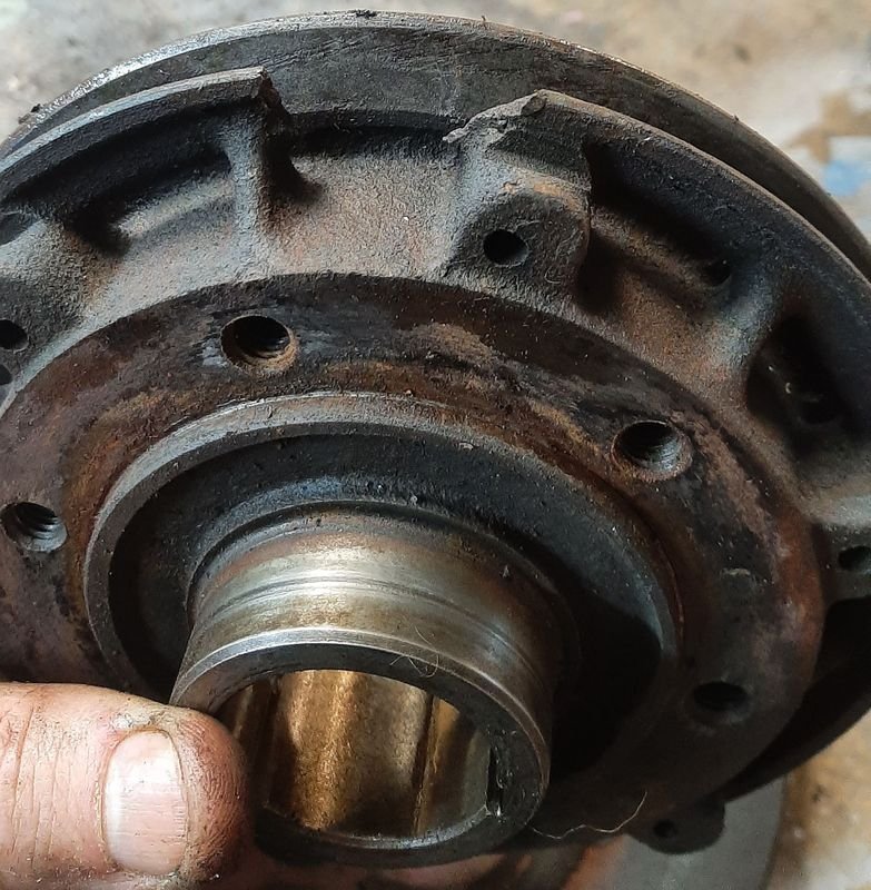
Old one had this chunk missing on the rear side that I only noticed just before leaving for Nats.
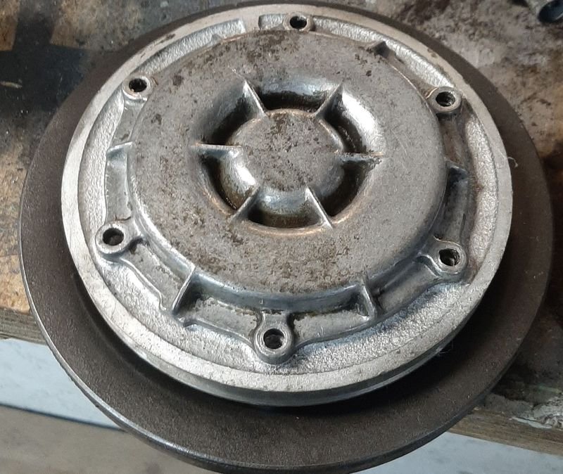
New one read to install along with a cleaned up and repainted balancer pulley and the centrifugal oil filter cover.
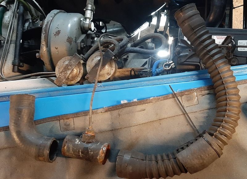
Removing the radiator also meant i could swap in the new factory lower radiator hose i got in, and swap out this nonsense.
Im now comfortable with trusting the factory temperature gauge, so i dont need this mechanical one any more either, but ill use this one in the van rather than the china electric sender one in there.
Used some phosphoric acid to clean the top of radiator while it was out and a respray as well
Lower hose in , much tidier, and the routing past the alternator is much better too, no rubbing on anything, and with the hoses sized to the different inlets and outlets its much tidier all round
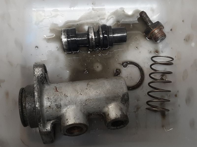
Clutch
Pedal feel on the clutch pedal had always been a bit funny (seemed to 'stick' at the top) and when the gearbox was out checking out the clutch was out there wasnt anything obvious mechanically wrong.
Pulled the master, which apart from some typical crusties in the pushrod end, seemed fine
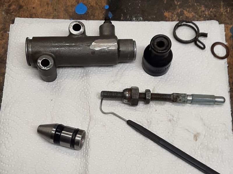
And the slave, again nothing scary, but worth tidying up and re rubber greasing everything
Ended up being the pushrod on the pedal, i thought it was not adjustable but it was just stuck ! , so now thats freed up and antiseazed up and adjusted a bit and it seemed to have sorted it. Swapped out the lever arm sping on the gearbox for a lighter one too, will see how that goes.
Clutch feel is like a modern car! Im sure ill have to adjust it a bit to set the bite point to the right spot once i get it off the jackstands but theres no feeling of sticking or jamming at the top of its travel now.
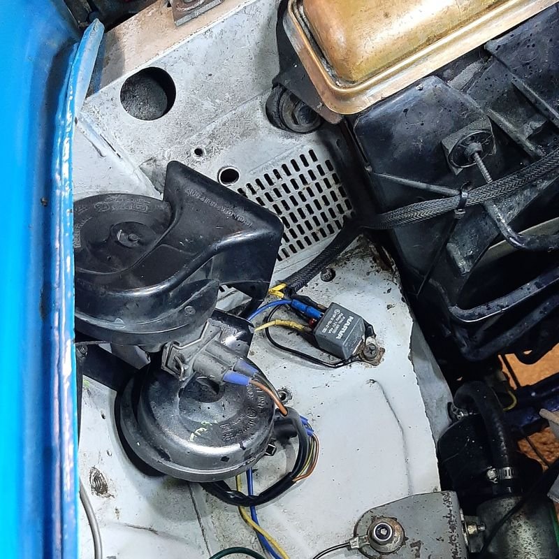
Electrical
This car has two horns from factory, there's a switch under the dash to switch between them - a Town which an electric piezo tooter that lives under the front wheel well, and a Country which is supposed to be two chromed air horns run off a chromed compressor that is supposed to live in the engine bay and point out that grille.
This car didnt come with the air horns, and ive found some horns, but not stumbled on a compressor yet (i have an eye out for a cheap chinesium one but no luch as yet)
Anyway the snail style horn i had was a bit weak and strangled sounding and i picked up a dual snail style horn that had a mounting bracket from some Audi at PickaPart when i was in Auckland last. Fits great!
No pics but ended up chasing a bunch of electrical gremlins (turned out the old horn itself was fine, the wire at the connector end had gone green/patinad, and was letting though anywhere from 8-10V meaning it sounded sick), and tidying a bunch of wiring, including pulling the fuse box and cleaning that up too. Everything is much brighter now
TOOT TOOOOT!
Also pulled the plugs, cleaned and gapped them (0.40mm); pulled the distributor out, filed the points flat, degreased and cleaned, and reset the gap (0.45mm),
Turns out the Vacuum advance diaphragm is blown
 Only makes a small difference and only at very low rpm, but ehhh.
Will probably need to send that off somewhere to get fixed, as ive not seen them for sale previously. I also have 5 spare ones that all have leaks too.
Also cleaned out the carb including blowing out the jets and the crud in the bottom of the bowls - quite a layer of fine silt, probably rust from the tank making it past the filter
 .
.
Reset the timing (12deg), tuned the carb, timing, carb, etc dialing in on the sweetspot and now starts and runs really nice.
Only a couple of things to do and it will be off the stands and as good as its ever been
.If anyone knows of a place that does diaphram preplacement let me know
-
30
-
well done untangling the magneti spaghetti.
I didnt see why you set off on this maniacal task tho?
IME the wire and connector quality itself is pretty good, but the layout and logic is messed up.
Is there a reason you replaced all the wires too?
I mean im all for it, just wasnt sure why?
-
- Popular Post
Had to go to Auckland for werk,
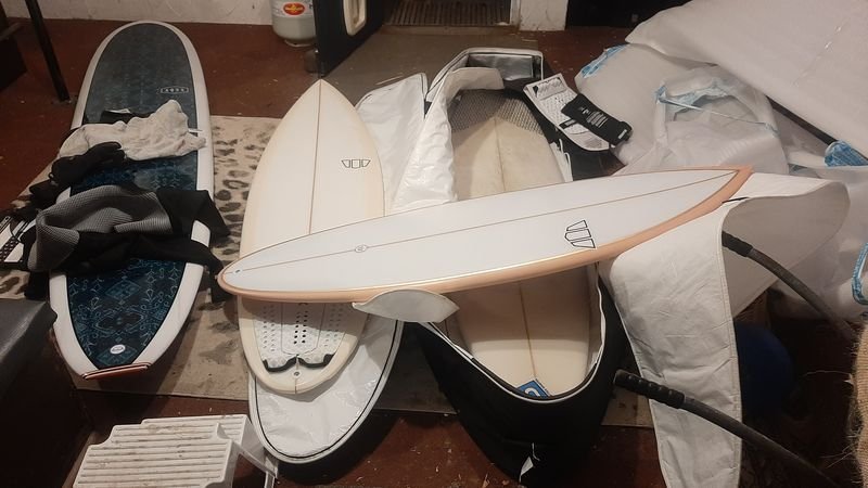
and came back with a LOT of excess baggage
My buddy sent me up with a coffin bag to get 'a couple of boards' ended up being 3 Surfboards (collected from GHS in Muriwai as a favour for my other Muriwai pal who lives down here too - a new 5'0" custom for his daughter and a couple of stockers for him), plus a new 9'2" Mal turned up for me in the post
And some gluten free fake meat from Blissful Foods on Mt Albert Rd - nomnom
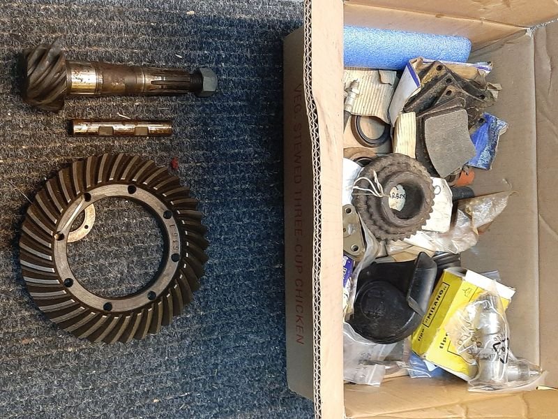
And managed to get out to the lockup to dig though the treasure
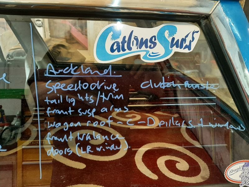
and filled my luggage with about 20kg of Car parts, including a box of 2300 treasure that id left behind last time such as a spare diff head, some starter parts and a speedo drive
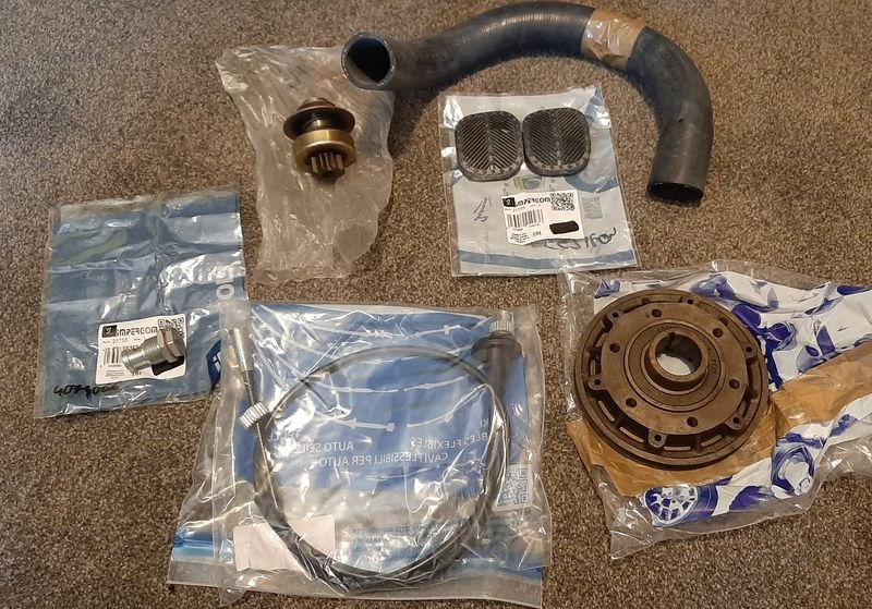
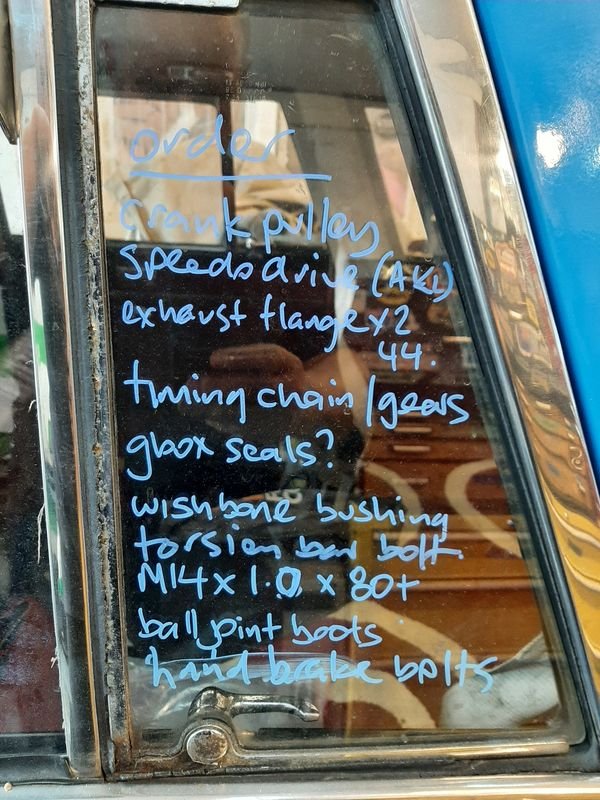
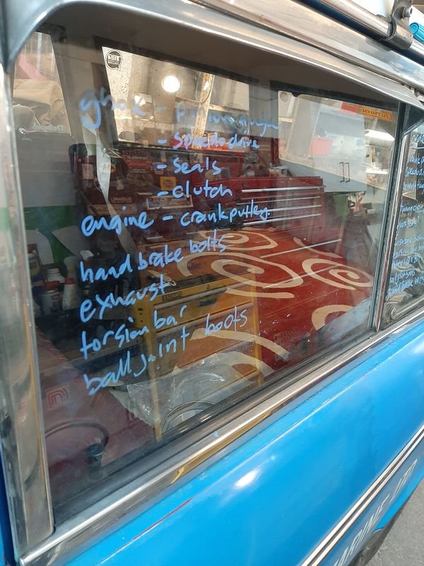
I also made an online order, including a starter pinion, pedal rubbers, a special 2300 only crank pulley, speedo cable and an oil pressure valve (for teh 1100T Van)
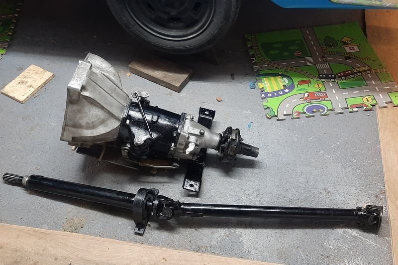
Next job on the list was really a bunch of 'while im in there' tasks all requiring the gearbox to come out
- gearbox leak(s)
- gear linkages had got noticeably worse over nats trip, to the extent i was having trouble getting into first
- get speedo going (speedodrive in gbox is busted)
- clutch is a bit shuddery
- centre bearing on driveshaft seemed loose
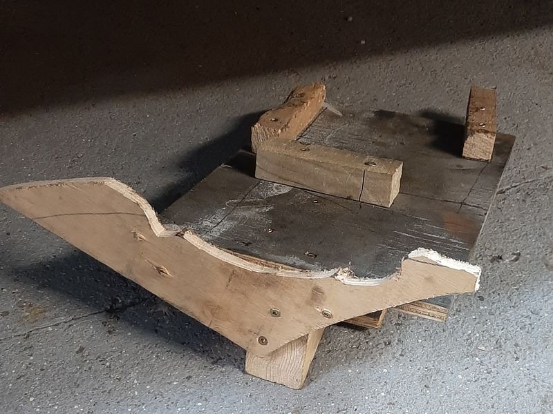
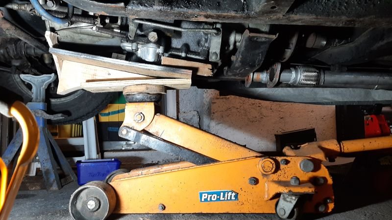
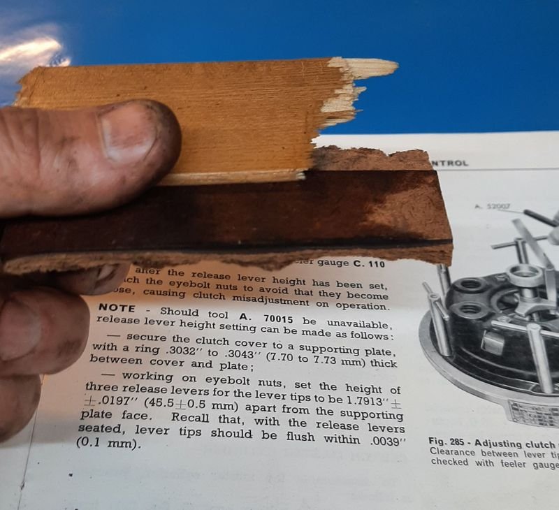
So, gearbox out, first, woodwork.
Bit easier than bench pressing it, and less likley to drop this cast iron deadweight right on its aluminium pan
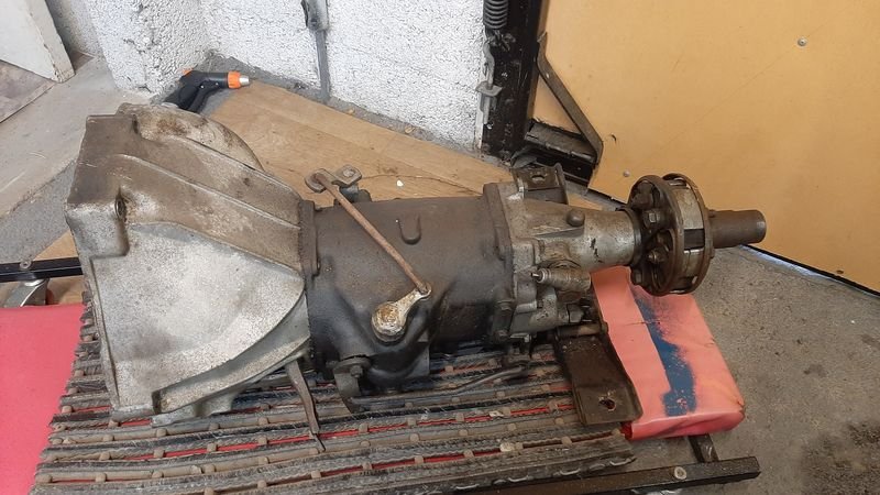
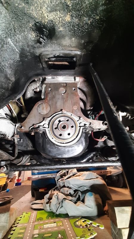
Lump out
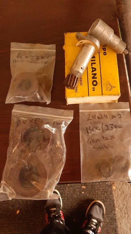
Gear box seals in stock
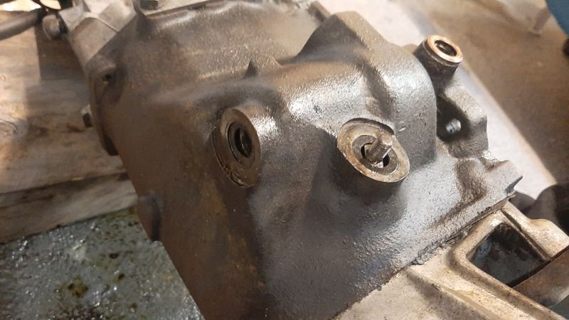
The front and rear seals were not leaking but the linkage seals sure were, 24x14x7 btw
Rear main nice and clean too, suspect a drip on the rear pan gasket tho.
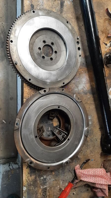
Flywheel clutch and pressure plate all good.
One of the clutch fingers was a bit higher than the other two so i adjusted that back down to match the majority. Hopefully that's the slightly juddery clutch bite issue.
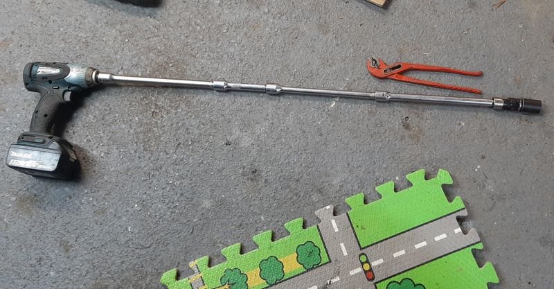
More woodwork - these wood scraps ended up being ~7.5mm which was good enough to make the alternative to Special Tool A.70015, which was unfortunately unavailable.
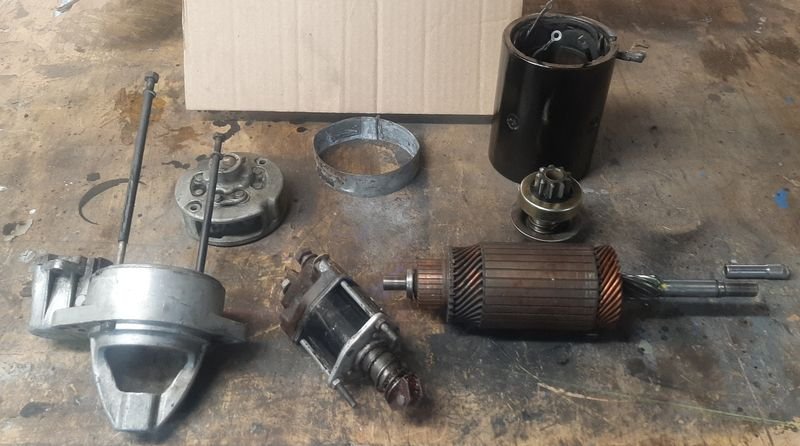
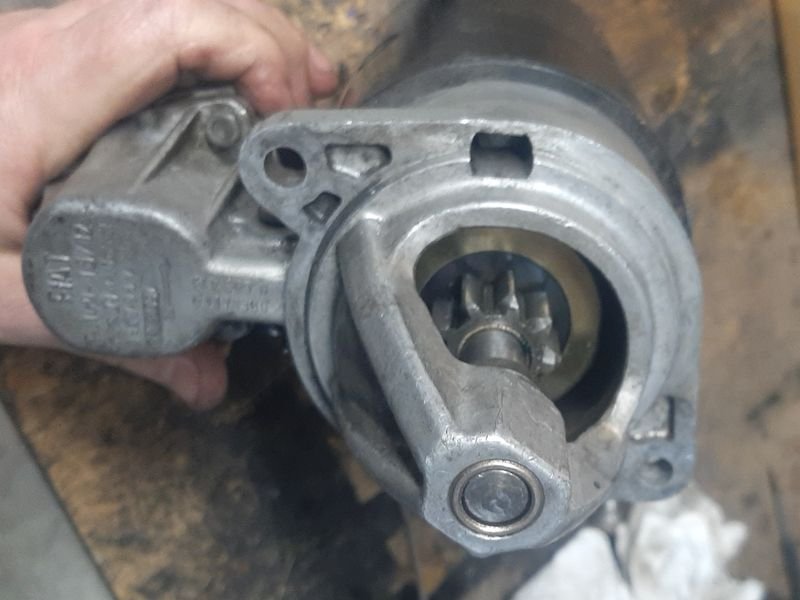
Pulled starter apart to replace the pinion drive which was running on - an issue since i originally got this going
All nice and clean with new paint, new bearing and new pinion
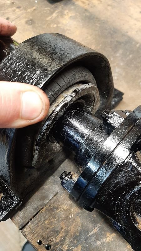
Centre bearing.
Was new ~5 years ago. The bearing is still fine, and the manual suggests the rubber is supposed to be a fairly loose fit.
Nevertheless it got the Sika Flex treatment whcih will hopefully protect the rubber and stiffen it up as well
Bits and pieces get 2k black with a brush.
Should last better than any single stage or spraycans all of which which ive used before and decided all are a total waste of time under a car imo.
All ready for reinstallation, cant see but the centre bearing hanger is all sika'd up, and there is some 4mm rubber strips under the small void that is supposed to be between the gbox mount and the xmember - mount was was soft from the gbox oil leak, should lift it a few mm back to 'as new' Hight and support/stiffen the mount back up and stop it from rubbing on the crossmember.
And then installation is reverse of removal as they say.
upper bell housing bolt special tool with all the extensions
Spent the weekend getting it all back in and adjusting stuff, including replacing a few linkage bushes and clips to tighten that up as well, and got it started up just before, and ran it though the gears on the stand.
Speedo works for the first time ever! Linkage is much better! Clutch works! Starter sounds great! Exhaust doesn't leak or rattle!
feels good man!
-
33
-
- Popular Post
Post nats i made some lists of fixing and getting .
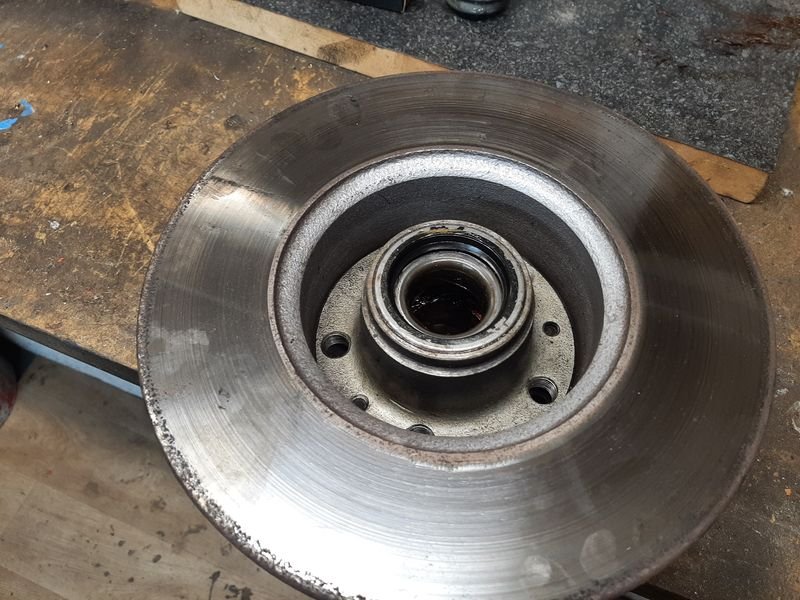
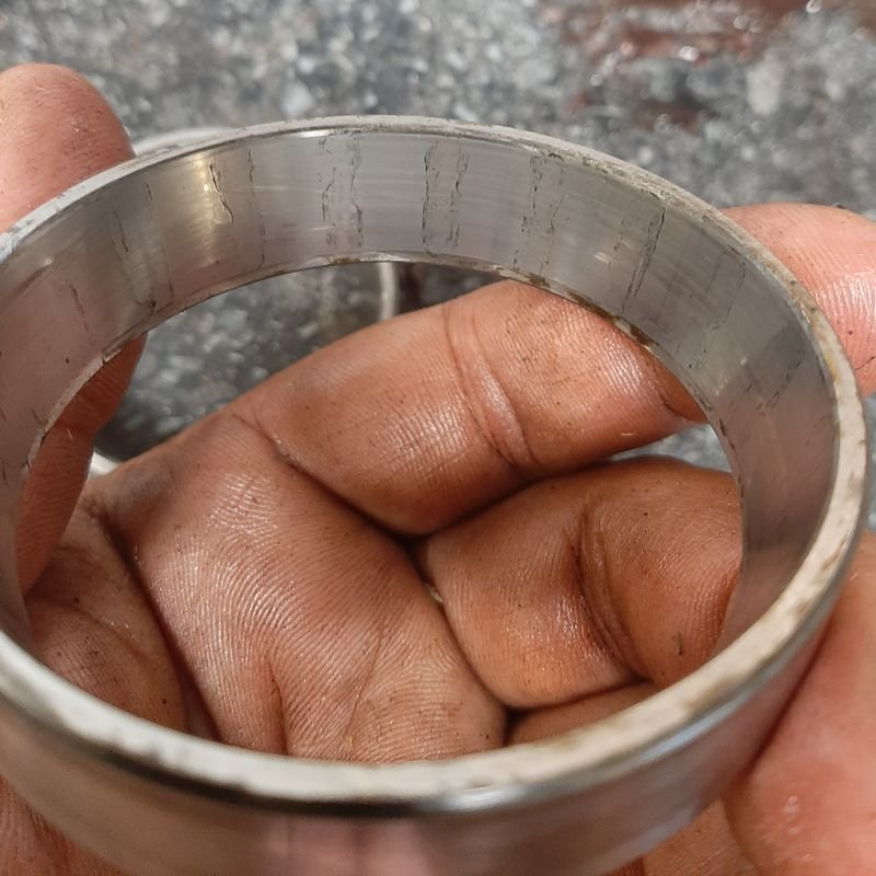
First job, swapping the other front wheel bearing that i didnt swap before nats that surprise! had started grumbling pretty bad on the homeward leg - wasnt getting hot just noisier,
i had it on board, but CBF changing it on the side of the road if i didnt have too
Another original factory fitted RIV bearing and seal on this side, swapped out.
Thatll do it!
Probably started with small rust pits from when it was sitting all those years, and after about 5000km on a kerosene clean and a regrease finally punched though
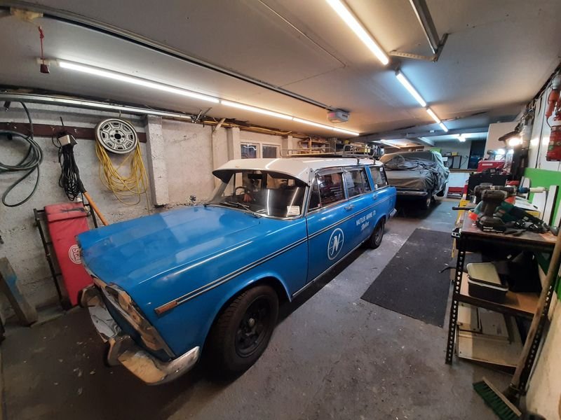
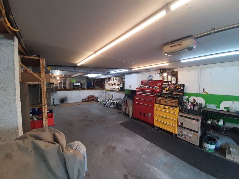
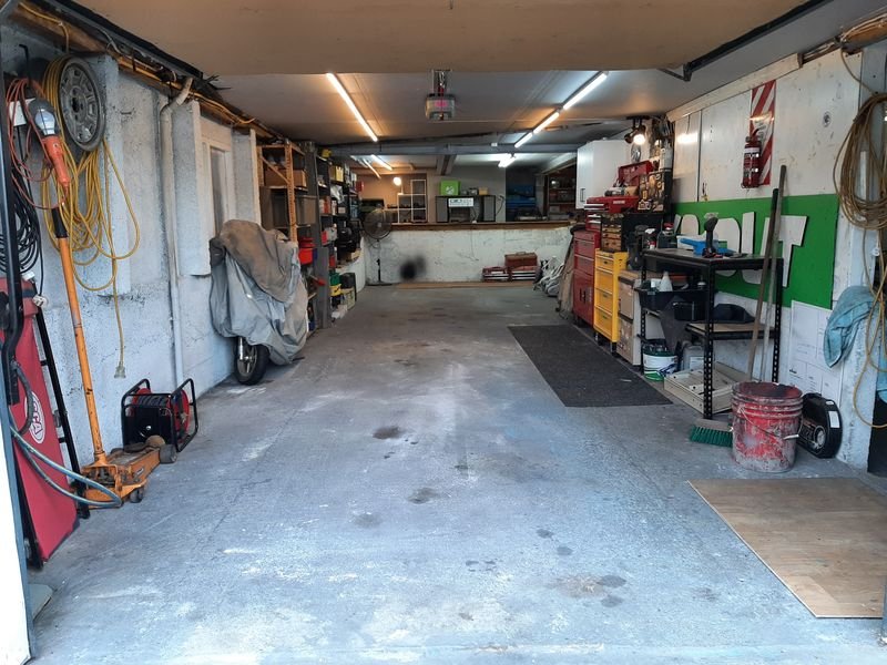
Then i put GIB on the front half of the garage ceiling/kitchen floor and some new lights.
Way better!
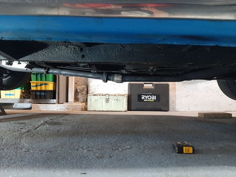
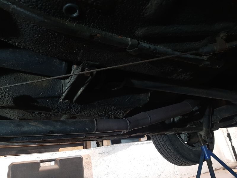
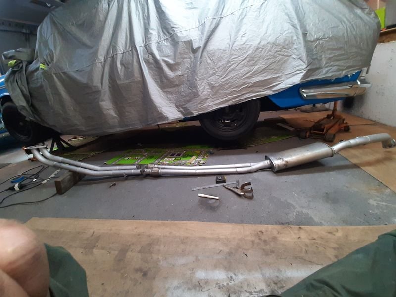
Exhaust - way too low, also, to loud (what?)
The old girl sits pretty low, and we had pretty bad exhaust scraping issues around Maharau and anywhere with judder bars really.
The constant battering made it bend mounts and droop, and leak and fume out the interior and i had to fix it a couple times at Nats.
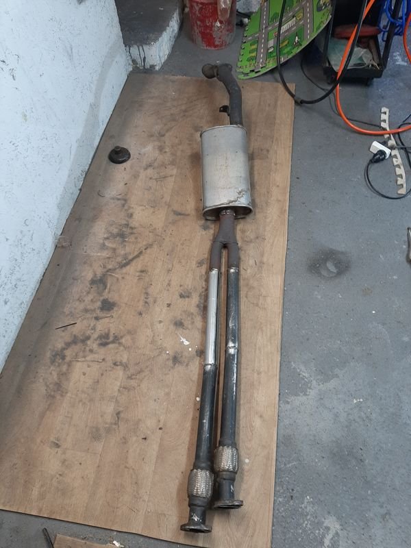
LOW LIFE
This before shot shows why - when i first built this i put the flange at the easiest spot to do up, but its also at the lowest point, right between the wheels.
It sounded pretty good , with long 1 1/2" secondary's to 2 1/4" just before the diff, into just one straight though muffler
but was also pretty droney, esp @ 2k and 4k rpm, and so the drones was nearing peak about highway speed (100 is ~3.5k rpm in 4th) .
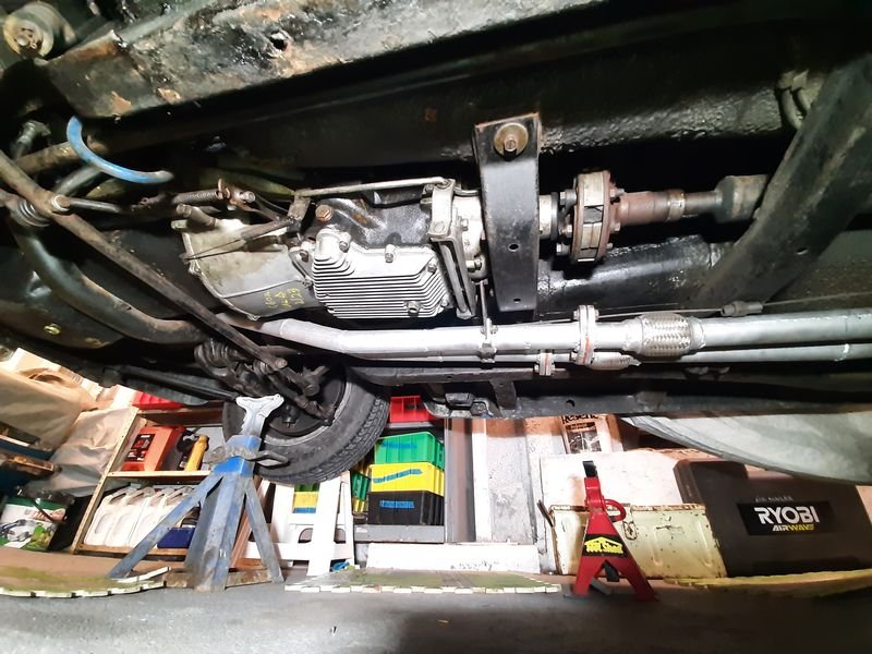
Ill move the flanges and flexis in front of the torsion bar mount/x member so all that can be both flatter against the floor and loose the 10-15mm extra diameter forward to a less scrapey location
Looking towards the diff - will put the muffler somewhere between the merge and the diff
Also Ms Azzurro was getting headaches, and declared she wouldn't ride in it again untill it was sorted out. So thats that then.
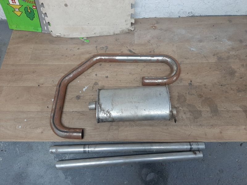
Basically need to tuck it up a bit more though the middle, by moving the flanges towards the engine, and stick in another muffler
Had these bits in the stash, some left over 2 1/4 and 1 3/4 pipe and a 2 1/4 muffler ex my 125
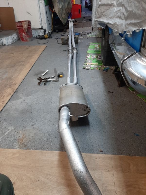
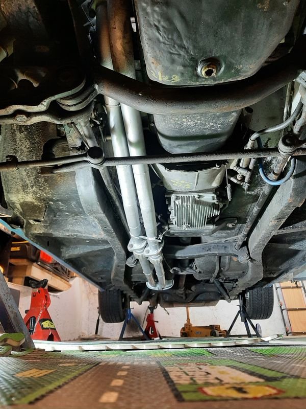
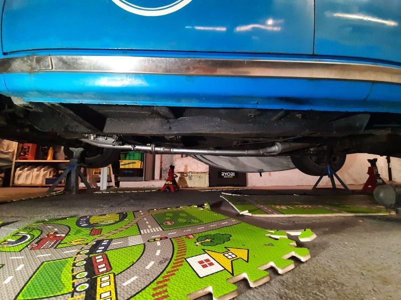
After much faffing this is the new rear section, new muffler before the diff, and flanges moved about 500mm forward and staggered
Shiny and chrome
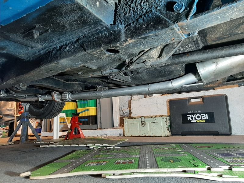
Still lower than the aluminum finned gearbox bottom plate with a dangly drain plug, but thats good.
Would like to build a sump guard/skid plate one day, but for now it remains to the exhaust to protect it
Loooong secondaries, but a few 100mm shorter, so be interesting to hear what that does to the harmonics - definitely had a noise peak at 2k and 4k before
Nice and tucked up and flat though here, the old exhaust had lots of scraping here so hopefully that small skid plate will stop the lower edge of the muffler getting hooked on a curb and ripping the whole lot off
Gained at least 10s of mms! Thats good!
Fired it up once the RTV set, exhaust sounds smoooothh, much lower volume, but has lost its race car bark. Sounds like a modern car quiet.
thats good to, i guess?
(I must be getting old)
-
21
-
Have used both of these before no dramas
Or
https://www.carbparts.eu/?lang=en
The second one is the feels slightly dodgy one i think you are thinking of.
Ive used aliexpress for scooter carb jets, but not weber/dell stuff
When i lived in auckland I called in to weber specs a couple of times, they had what i wanted in stock, but was very spendy. murray knows his shit but both times made it pretty hard to enjoy giving him my money, so ive not since, but, ymmv
-
That pic is in the freshly graded & gravelled yard before the big shed went in right where those are parked.
Sick, thanks chaps, ill pass them on to the big boss man.
-
3
-
-
Ill have a look at mine, i have an internally regulated alternator on my 125 - from memory it was as simple as unplug the voltage regulator and plug a couple of those wires together, but exactly which i cant recall.
Im probably explaining it wrong, but in my mind, the alternator light on the dash works on the basis of who is winning the Battle of the Volts (path of least resistance?) between the alternator and the battery, if the alternator is pushing out more pressure (volts) than the battery, the pixies can then take the path that avoids the lamp (which is also a resistor - that why you cant use a LED there), but if the battery is winning, the path though the bulb is taken instead (cant push though the regulator??) and so it lights up.
How that relates to the wiring idk, but now my brain is mush, and you are now stupider for reading this, ill go take a look and report soon
-
1
-


oldschool spotted
in General Car Chat
Posted