Adoom
-
Posts
2188 -
Joined
-
Last visited
Everything posted by Adoom
-
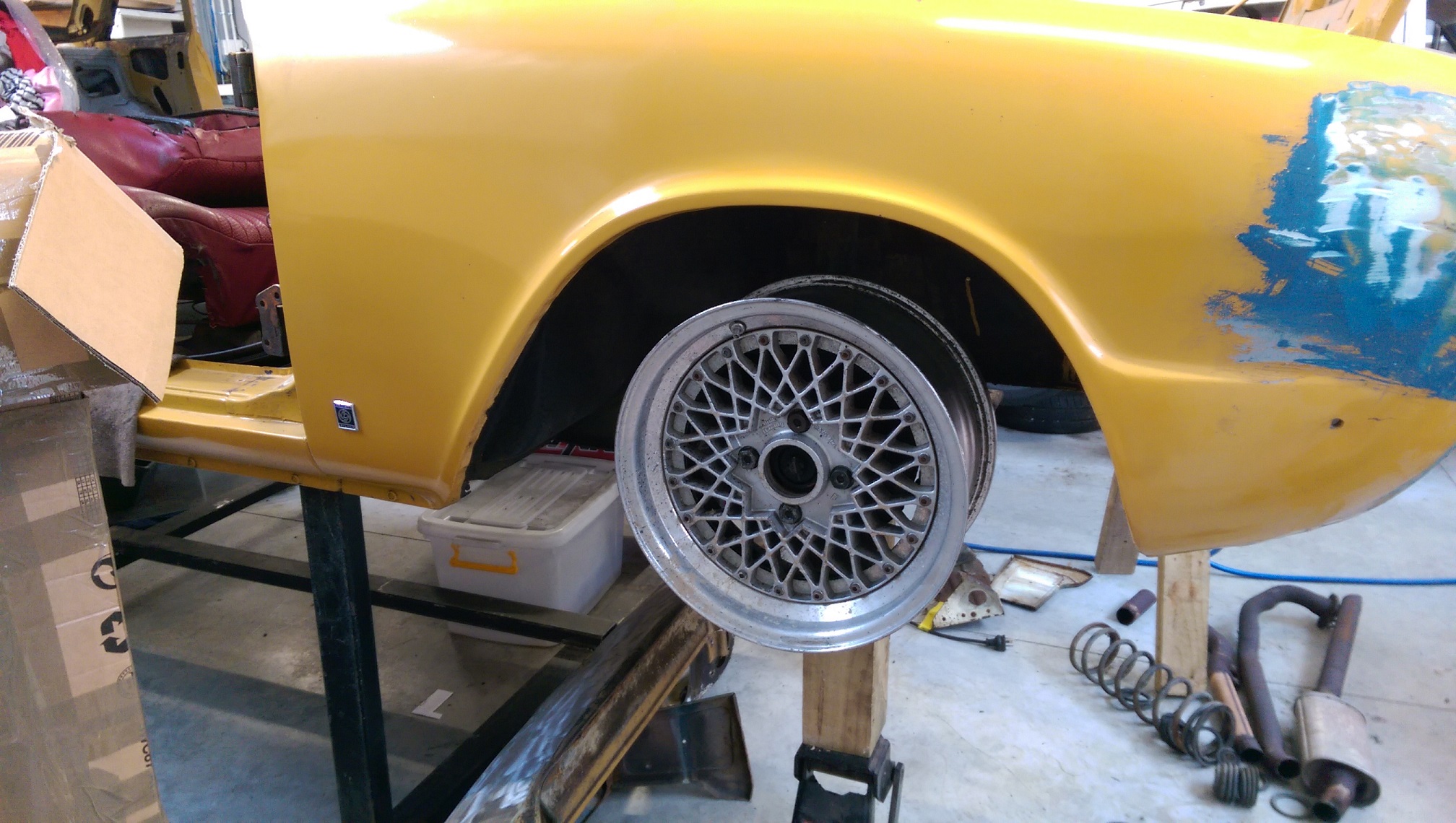
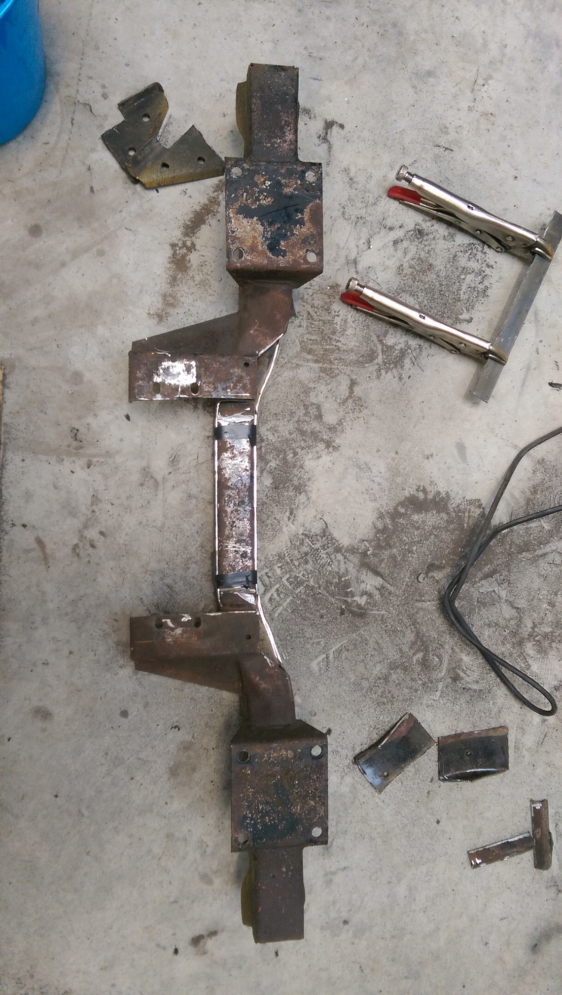
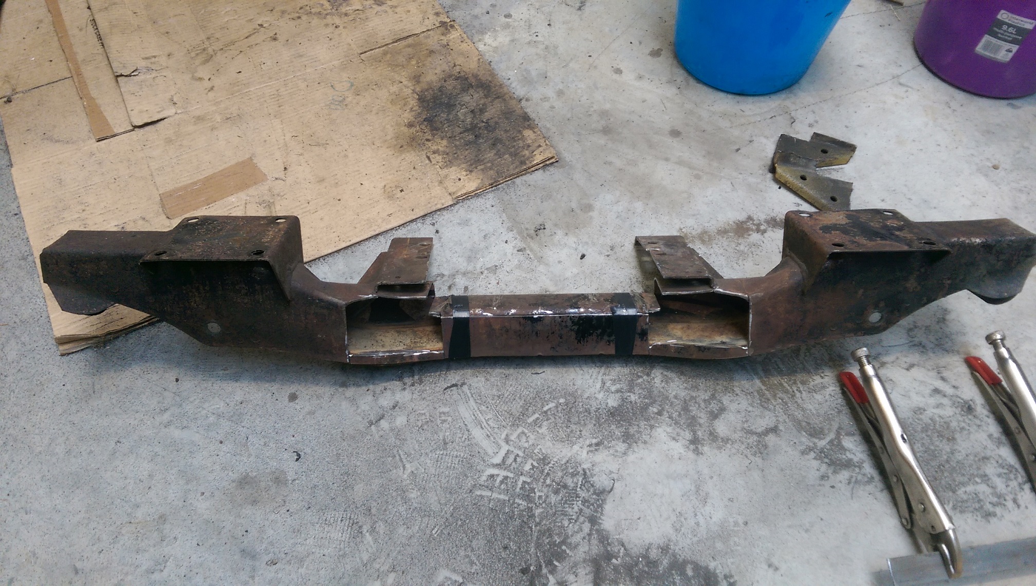
I've been keeping an eye out for a set of these in 15". Some appeared on Tardme last week and they were in driving distance to collect too. No one else bid.... so I probably paid too much. The centre needs to be gold. I wanted 15" so I can put bigger brakes on the front. I also made a start on the jig to narrow the rear subframe by 145mm. The subframe will be welded to the two inner lengths of angle. And the two outer bits of angle are parallel and welded to the bench. Once I think the subframe is sufficiently braced and welded. I will cut a section out of the middle of the two inner bits of angle. Then I will be able to chop bits out of the middle of the subframe and 'just' slide the two halves closer together while still keeping them aligned. But I ran out of mig wire. On a weekend.

-
This could work, but is it certifiable?
-
The engine is now as far back and as high as is practical, so... Hack hack hack. Don't worry, I have another. Now the cross member bolts on again and clears the sump. But the steering rack needs to be, much, lower to fit.
-
Welding was one. Is it a "under no circumstances can anything be welded", or can it be done but it has to be done "this way" and tested "this way"? Basically, I want to lower the steering rack in the triumph. The material I have read so far (in BOOKS, not forums) makes it look doable without worsening bump steer. Basically I need to lower the outer tierod end the same amount as the rack. And measure the bump steer before and after making changes. The book has plans for a very simple measuring device. The problem is the tierod end and how to make it lower. Some people replace the tierod with a rod end bearing and use spacers to change the height. But is this acceptable on a road car? Another possible option is to flip the tierod end over and mount it under the steering arm(std location is on top of the steering arm). But then the taper is wrong... So is there an acceptable way to make the taper go the other way? Machine a bigger reversed taper and use a sleeve? Fill the taper with weld and machine a new taper(probably not)? Make custom steering arms? They are made or forged steel, so is there any acceptable alternative material? I checked to see if new arms were available and maybe I could enquire about the availability of blanks. But it appears that rimmers and chris wittor have only 2nd hand arms. I've just seen a photo of a manual and power steering steering arm next to each other and the power steering arm looks like it mounts the tirerod lower. I'll have to see if I can get some to see...
-
Does anyone have the Steering chapter of the LVVTA Car Constructors Manual? I tried to buy it, all legit like, but it wouldn't accept my credit card when I tried to pay the $11.
-
POR15 sold the sole distribution/import rights(for AU and NZ I think) to apparently Bunnings, months ago, without telling the existing NZ distributor(PPC). AFAIK, he found out when he tried to do a stock order. I haven't seen any sign of it at Bunnings.
-
It's going to be a street car. I have a front sump that came on the engine. I also have a 'rear' sump from an SC400, that I paid far too much money for, currently installed on the engine. I will exhaust all other options before hacking into the sump. Cutting the firewall is still an option, it just means I'll have to modify/replace/move/something the heater. The further back the engine goes, I gain a little height so the engine might be able to go higher. I have come across references to Sparrow's stag. But I have no real names or contact details. All his photos on OS are dead. I think the only one I have seen is from the top of the engine bay. I found another guy on Lextreme with a Stag in Australia. http://www.lextreme.com/forums/index.php?threads/vvti-goodness-into-a-triumph-stag.15649/ He "As a result I had to make a custom crossmember. This has been a time consuming task as it is a complex shape and I had to make sure I didn't introduce bump steer by lowering the steering rack. To do this I had to make custom steering arms." and he cut the sump. The photos are few and from too far away to make out much detail.
-
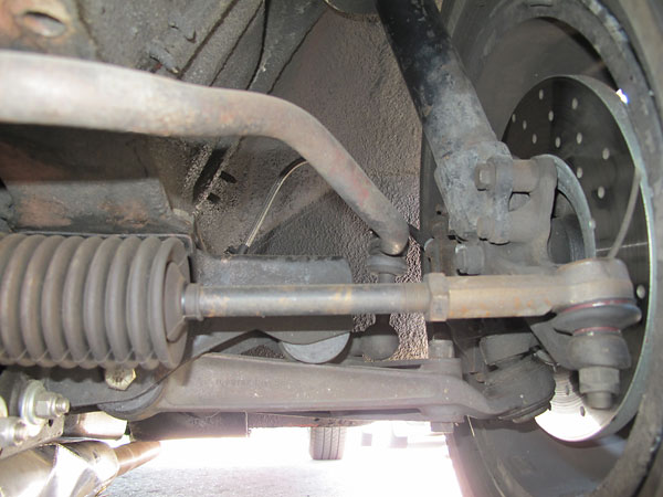
So I had a thought. The steering arm has the ball joint mounted on top, like this. (Not my car) If I moved the ball joint to the bottom of the steering arm, I could move the rack down quite a bit. I'll need to check if it then gets in the way of a wheel. Of course the taper would be the wrong way, but I could get it machined and sleeved to fix the taper. Right? @cletus Or is this also going to affect bump steer.
-
Looking at some engine photos... Only 25mm can be taken out of that front section, not the 50mm needed. The crank and oil pickup pipe use the remaining 25mm.
-
The front ~100mm(half) of the alloy part would need to be made flush with the bottom of the block.
-
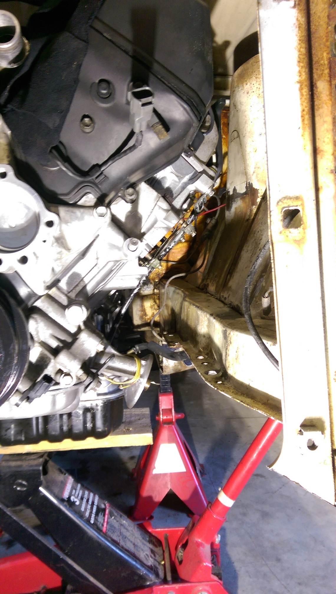
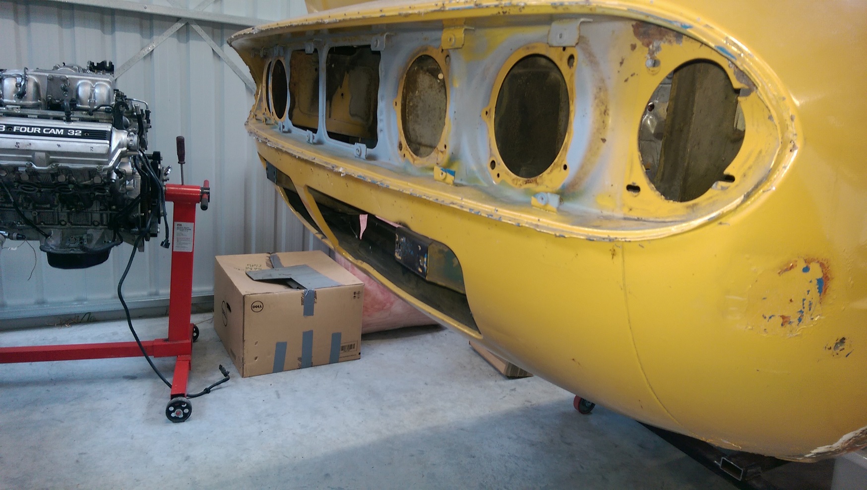
So I offered the engine up. And it's tight. I have since removed the heat shield thing from the alternator and got myself a little more space. I might grind down the lug the shield bolts to too. The alternator mounts are not adjustable, it can't get closer to the block anyway. I'm going to have to make 'log' exhaust manifolds. The engine came with some shiny stainless extractors, but there's no way they will fit. I'll have to remote mount the oil filter and remove that filter housing, it's in the way of the steering rack. The major problem I have yet to solve is the front alloy part of the sump is entirely in the way of the rack. So, recently, when I have been going in the garage, I find that there are heaps of dead flies. I think they must be getting trapped and dying?
-
So I offered the 1uz and W57 up to the Triumph 2000. On paper, it fits. In person, it's really tight. I won't be able to use those shiney stainless extractors that came with it. The main problem I have is the sump and the steering rack want to occupy the same place. The rack is mounted to the front of the cross member. The cross member also has the lower arm mounts on it. If I raise the engine, I'll need to start cutting holes in the bonnet, which I'd like to avoid doing. I already need to notch one of the bonnet ribs to clear the throttle body. Then I thought if I could move the rack mounts lower. But that will give me bump steer, which is bad. I came across photos of a Triumph stag(front end is basically the same) with a 1UZ. In one of the few photos(fuck you photobucket) it looks like he has spaced the cross member down. What would be the downside of lowering the cross member with the rack and suspension mounts? Probably as much as 50mm! As far as I understand, the effect on the suspension would be the same as if I had lowered the car 50mm...
-

Tristans 1973 Triumph 2500 PI Saloon
Adoom replied to triumph...tristan's topic in Project Discussion
What's it cost getting wheels from Japan? My thinking is that the freight alone would make for a really expensive set of wheels, so I've never looked into it.... -
So Total Bodyshop recommended this PPG two way thinners http://totalbodyshop.co.nz/item.php?id=4995 to use with the Etalon epoxy primer. http://totalbodyshop.co.nz/item.php?id=8212 Does that seem right?
-
I've used POR15 a lot in the past. Discussion on this thread argue that epoxy primer has just as good/better adhesion than POR15 but is not as picky about the surface prep. Total bodyshop told me when I was there that they cannot get any more POR stock(there was SFA on the shelf when I looked). Also, AFAIK, Permanent Painted Coatings was the authorised sole NZ importer. But the POR15 manufacturer has sold the Aus/NZ distribution rights to Bunnings without even bothering to tell PPC it was happening until after the fact. I got this info from Road and Track when I ordered some stuff(they called PPC while I was there). This all happened before xmas... I've not seen any POR at Bunnings yet. So... 2k epoxy primer
-
Why have you run a separate earth lead all the way from the back to the front of the car and not just earthed it on the body? Is it something to do with your 'hiding wiring and pipes in the engine bay'?
-
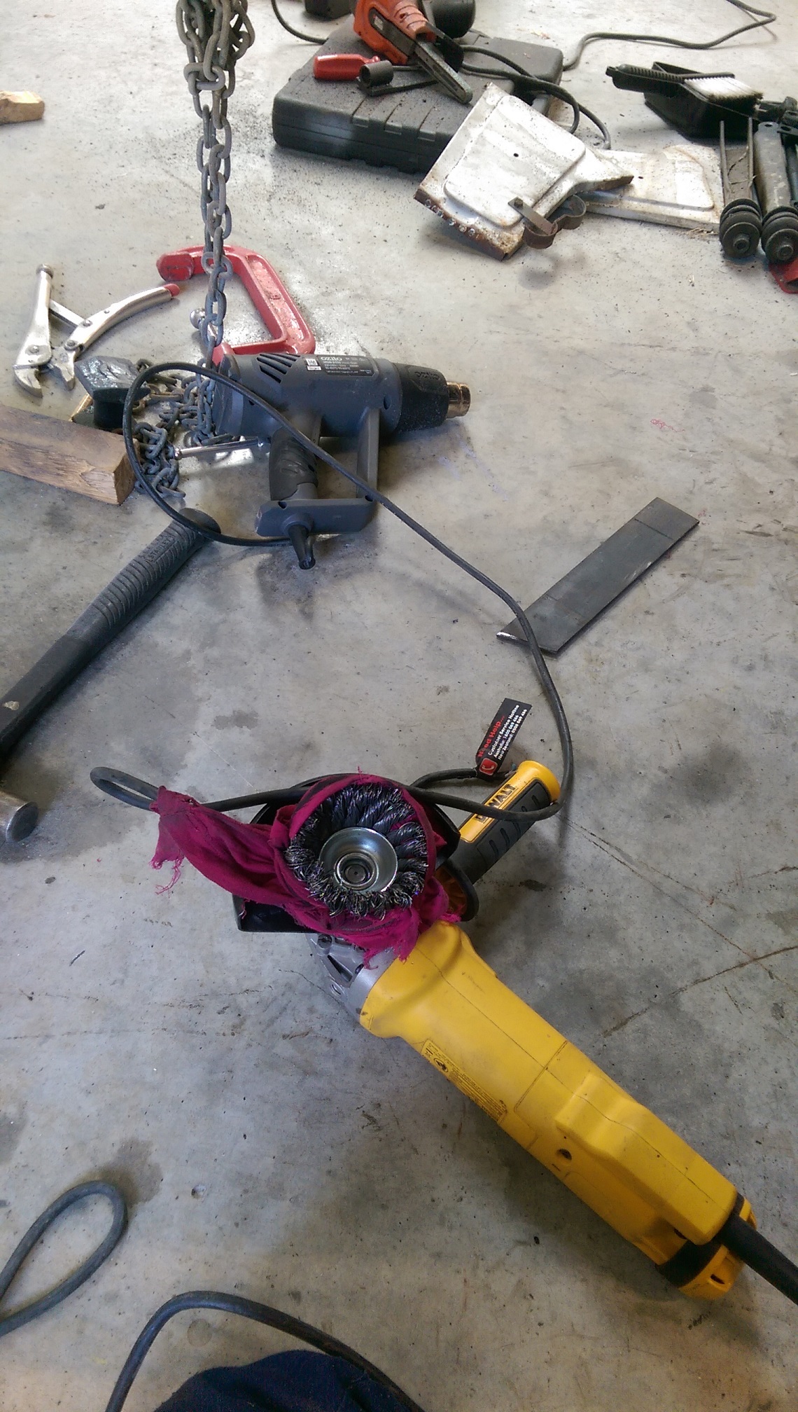
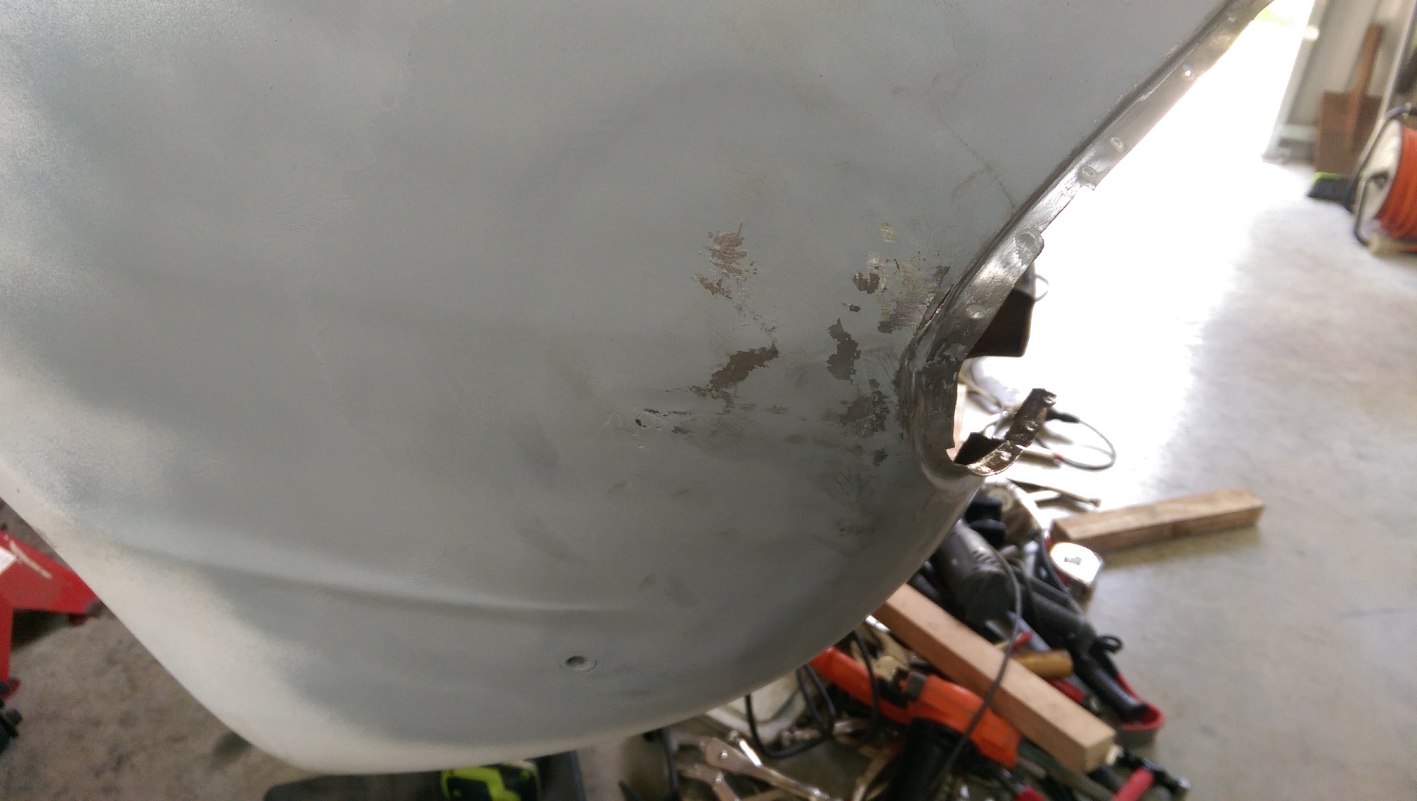
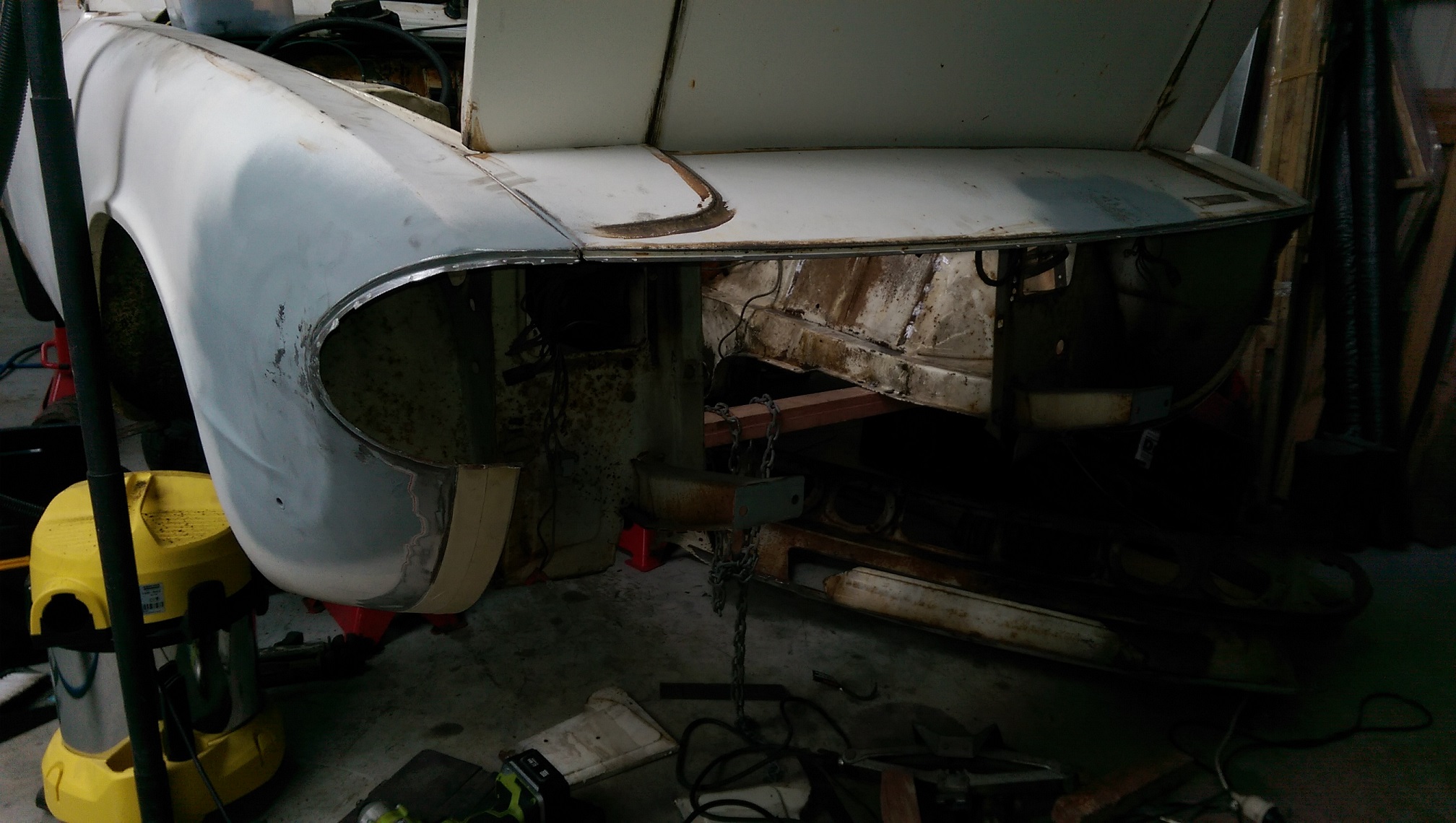
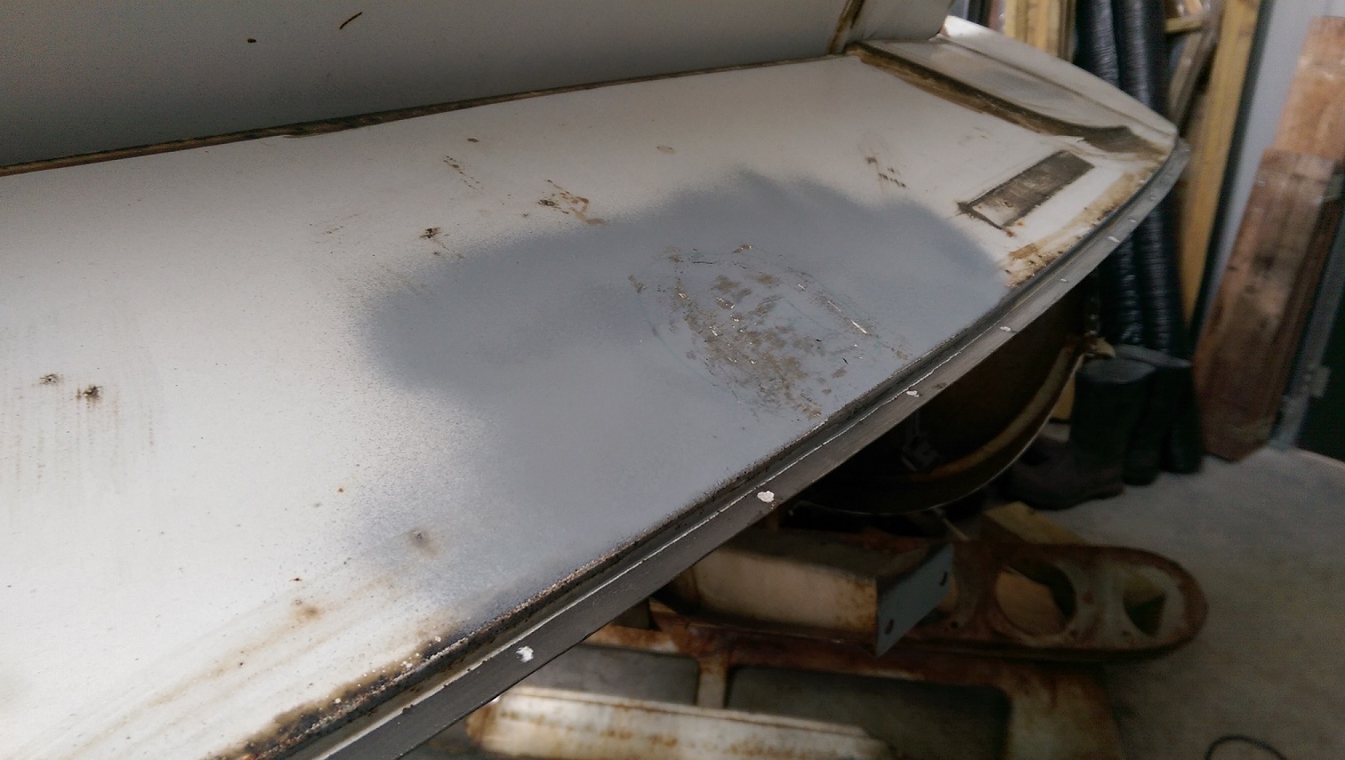
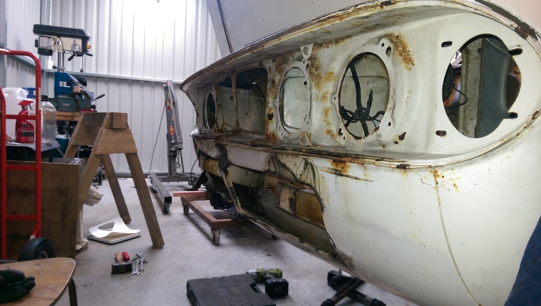
This time I added the overalls and the beanie to the safety glasses, ear muffs and dust mask. So now I'm not entirely covered with tiny metal chips. So I did some more die grinding to remove the front of the white one. I left a wide strip of metal beside the seam because the donor panel is rusty there. The lighting is not the best for these photos... It took five minutes to fix the dent that was here, now that I can access the back of it. I have greatly improved the dent in the wing. Still needs work though. I used one of those abrasive pad things on the grinder to clean the paint off so the spot welds were easier to find. But I could not fit it in some places, so I used the cup brush of death. It caught the corner of a panel and pulled it self out of my hands. So I held on better.... And it caught on the same corner and ripped it self out of my hands and fell on the floor instantly eating a rag and the power lead for my heat gun then jamming before I could pull the plug out. Kinda my own fault for having a messy floor.
-
Is this etalon stuff the right stuff/any good? I want to use it to brush paint the back of panels/cavities/box sections for rust protection. http://totalbodyshop.co.nz/item.php?id=8212 I was also looking at the ppg epoxy primer and epoxy urethane primer, but when you add hardener, it gets expensive. Especially since it is way more hardener than I need for the job and they suggest the fast/25 min/D803 hardener for brush work, which I guess it's not really suitable for spraying.
-
Doing it this way means I have easy access to the back of some dents. And I can rust proof and paint the backside of all those panels before I weld them back in.
-
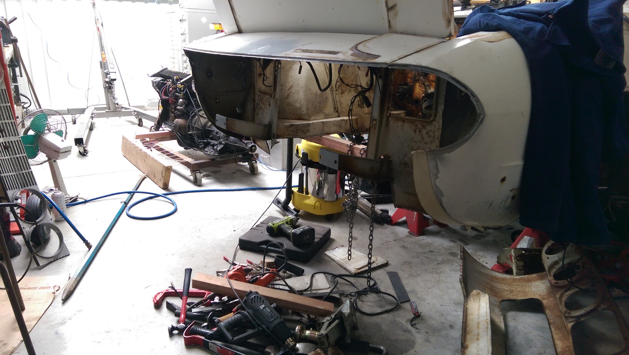
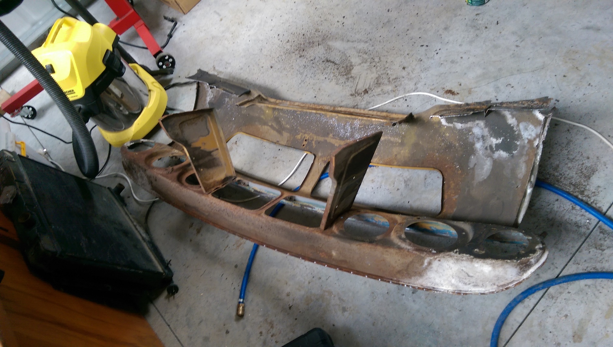
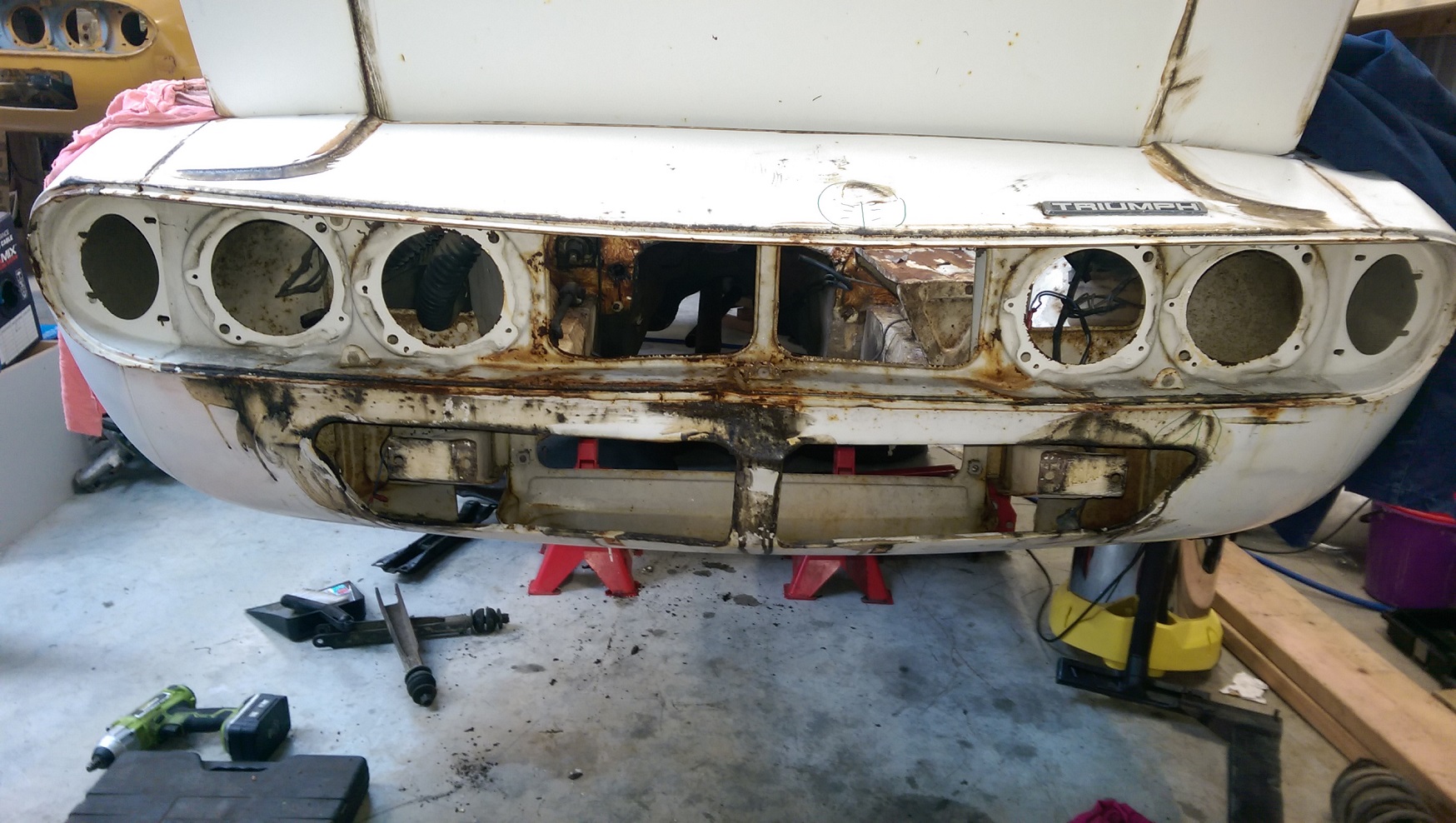
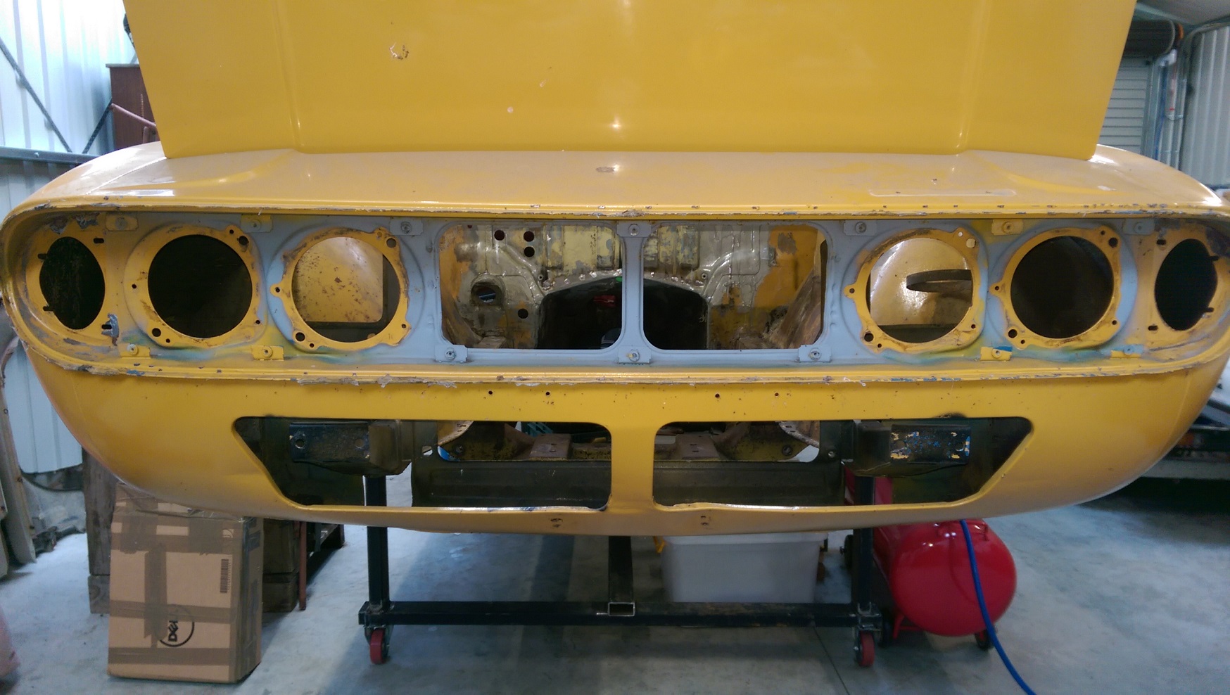
So I got the front panels to what I thought was a reasonable condition. Then I tried to fit the grill. And the space is not tall enough by 10mm. The front seam also still needs to come forward by about 5-7mm along much of it's length. I tried using blocks of wood and a long lever, but I've kinda given up trying to make it the right shape. I mean, I'm going to cut up the rear end of the yellow one to trial fit the nissan subframe anyway.... Why not cut it some more. I used my die grinder with a carbide burr, showered myself with tiny metal chips. I ground away metal from the spotwelds on the panels I am not reusing, so the bits I am using have no holes in them. I will do the opposite on the white car, then drill new holes to 'spot' weld it with the mig.
-
Discuss here about Yoeddynz's little Imp project...
Adoom replied to yoeddynz's topic in Project Discussion
I pulled bags of this stuff out of both my Triumphs too. It looked like yellow wool? -
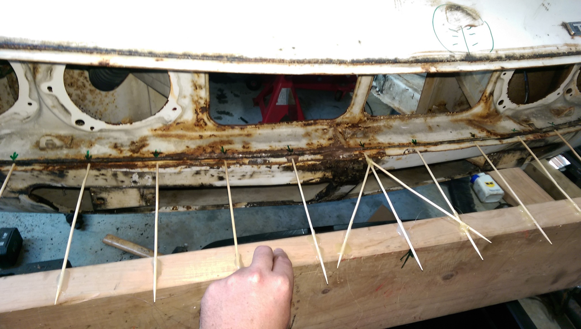
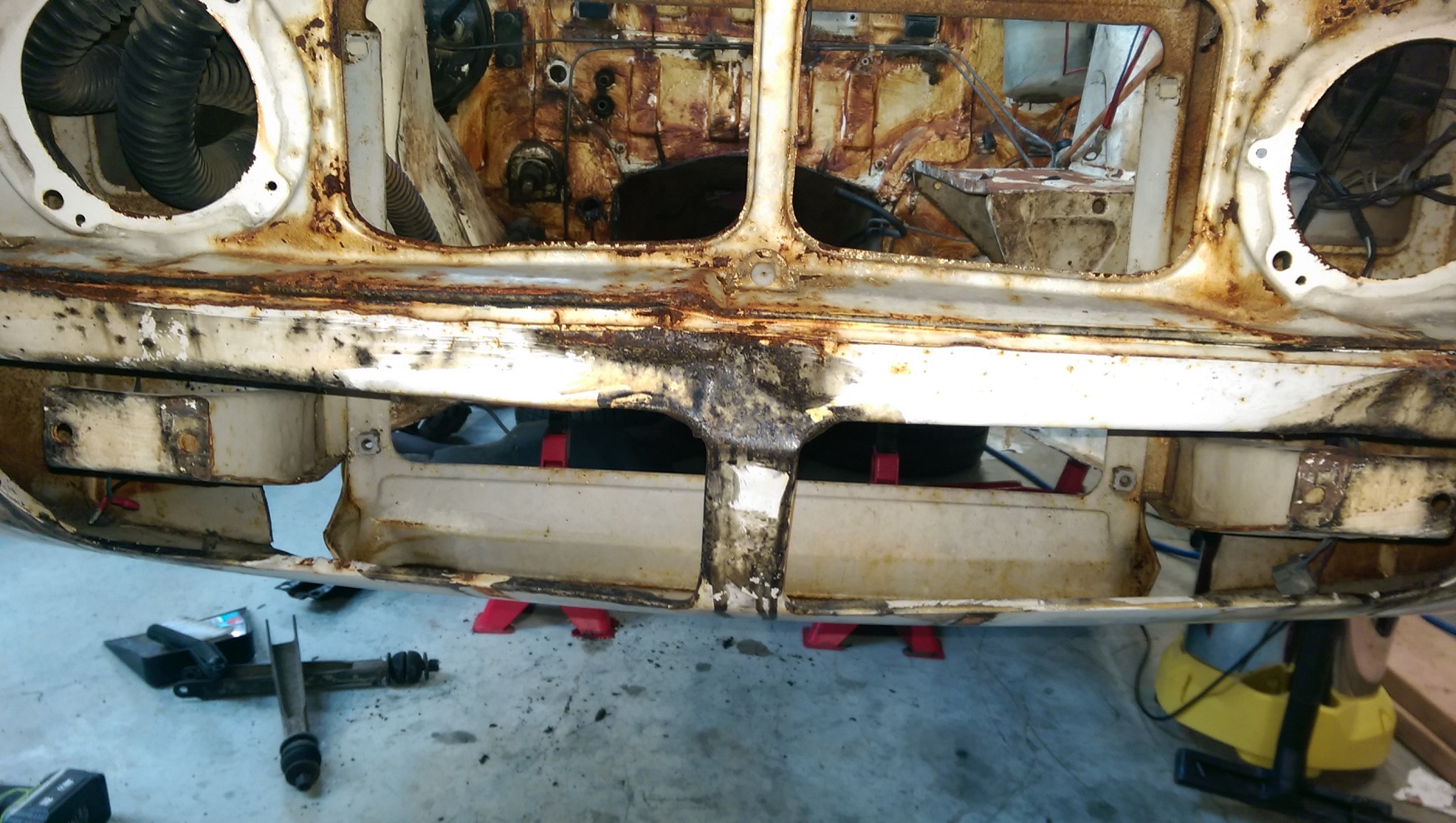
I tried pulling out the seam using a pair of vise grips attached to a slide hammer. Unfortunately, the grips(Even when REALLY TIGHT) would pull off the panel before moving the panel. The most effective method of "roughing out" the panel was to use a bit of wood and a big mallet from the back side. After bashing on it a bit I thought I had better find some way to measure my progress. I made a profile gauge... When I had stopped for the day, I got this far. The largest gap is about 5mm now. It started off about 10-15mm. The impact looks like it has pushed in and up, so that little 'shelf, behind my arrows,' is sloping up towards the back when it should be just about flat. It's awkward to hammer down because there is not much room to swing the hammer.
-
I think I'll go buy a slide hammer(I don't have anything suitable to make one). I want to try use one of the 15 vise grips I have to hold on to the seam and work out a way to hook the slide hammer to the adjusting bolt on the vise grips.
-
That was the original plan, then today I thought.... why not just cut the straight panels off the other one... I need to rig up some kind of pulling contraption with a long lever, or threaded rods, to pull that seam forwards.
-
@tortron And for reference....