bean.101
-
Posts
136 -
Joined
-
Last visited
Everything posted by bean.101
-
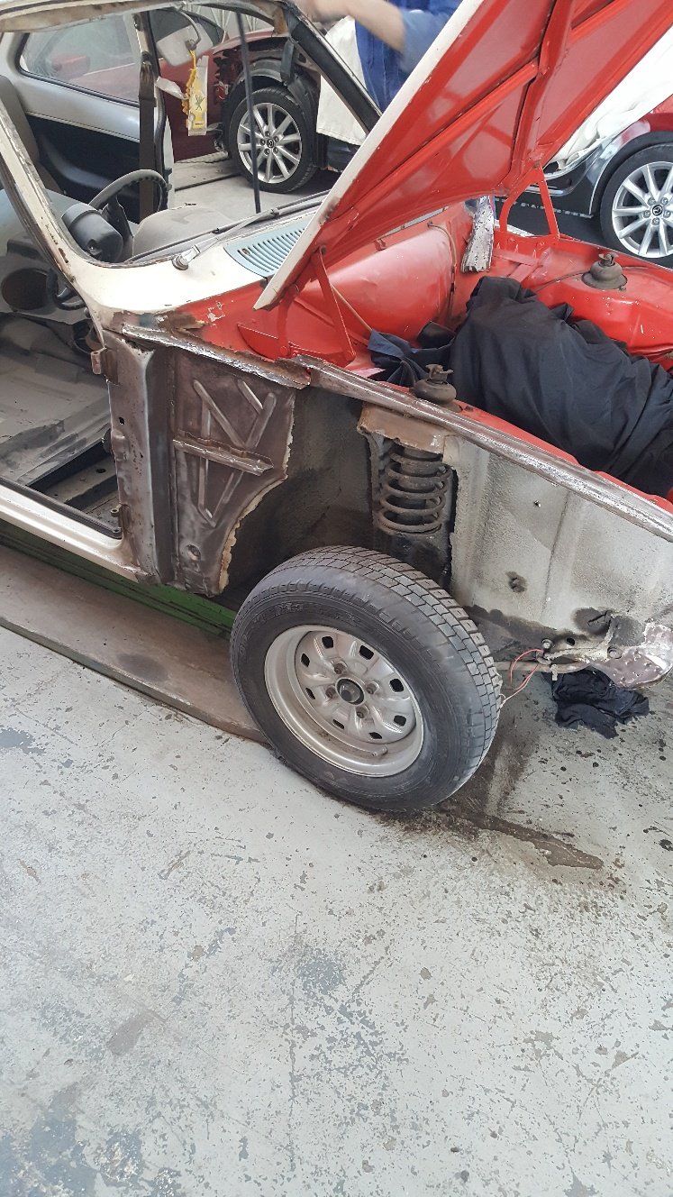
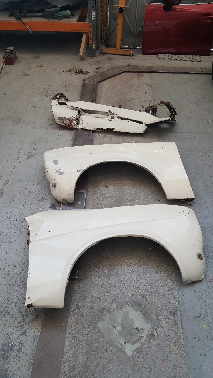
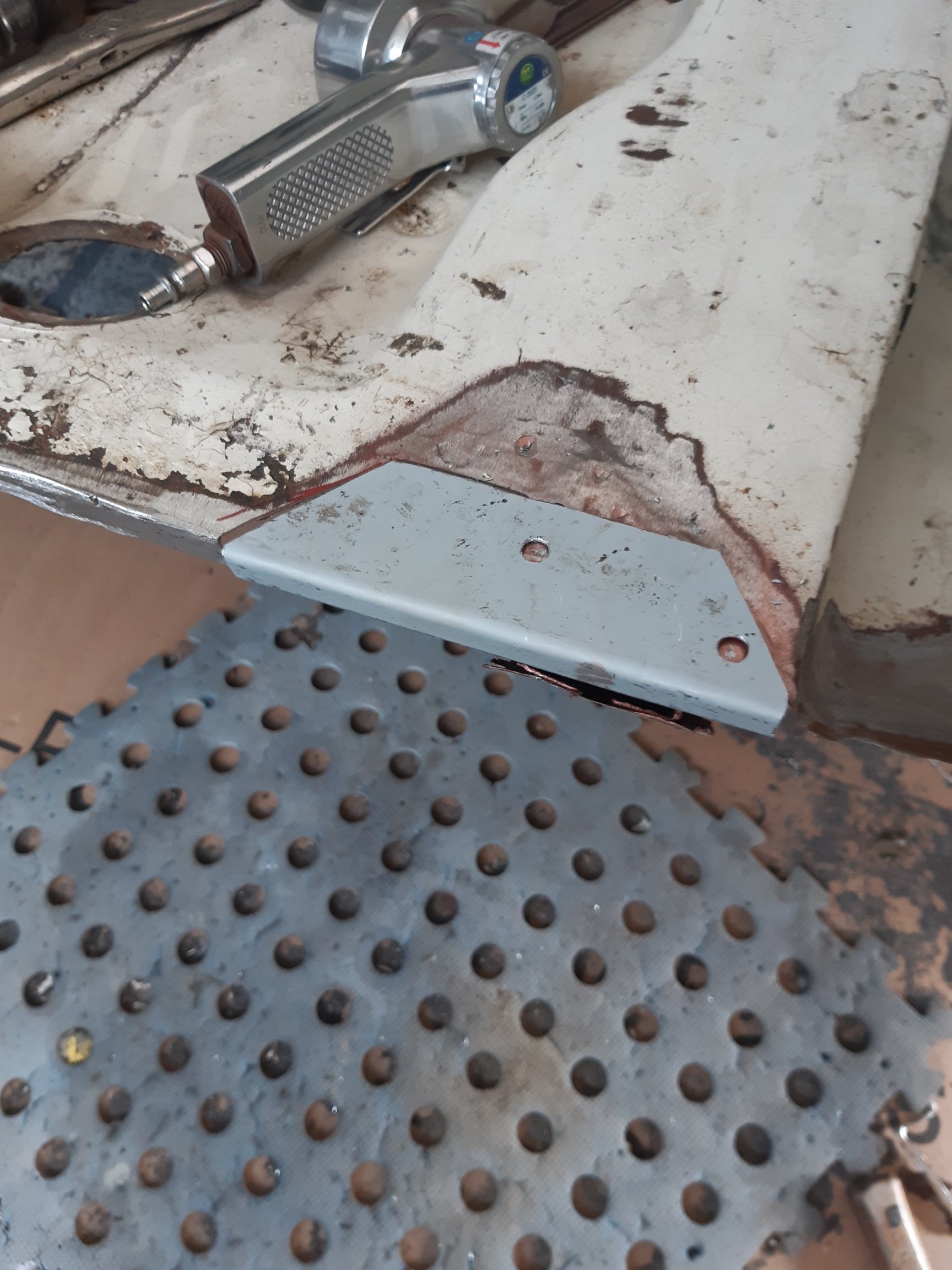
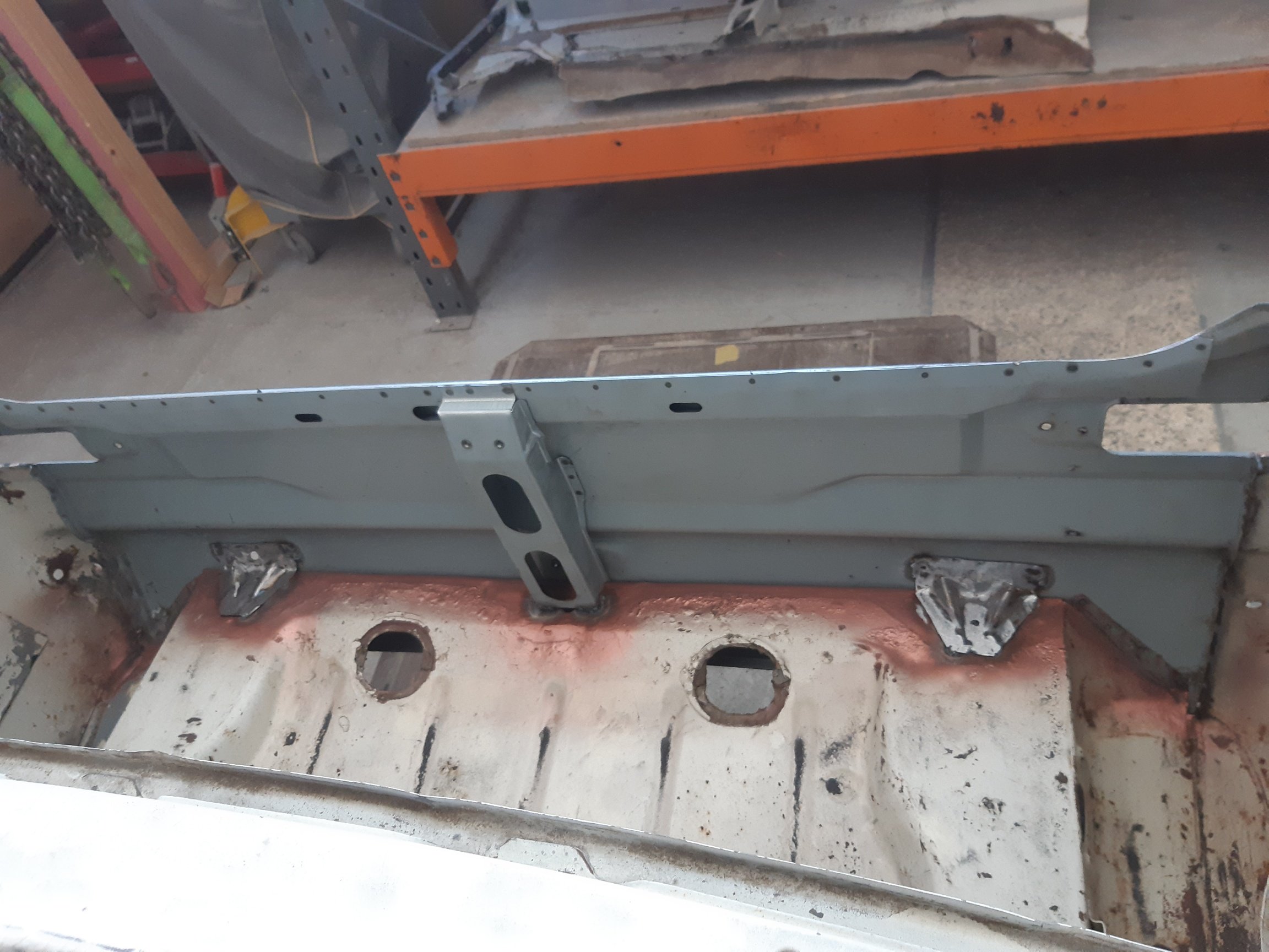
More progress. Front guards and front panel removed. I have bought old new stock Mexico Gaurds. And the front panel had rusted out where the number plate mounts. So new front headlight panel to be fitted. I will fit some new flitch panels. Rust sorted. Ready for the new panel.

-
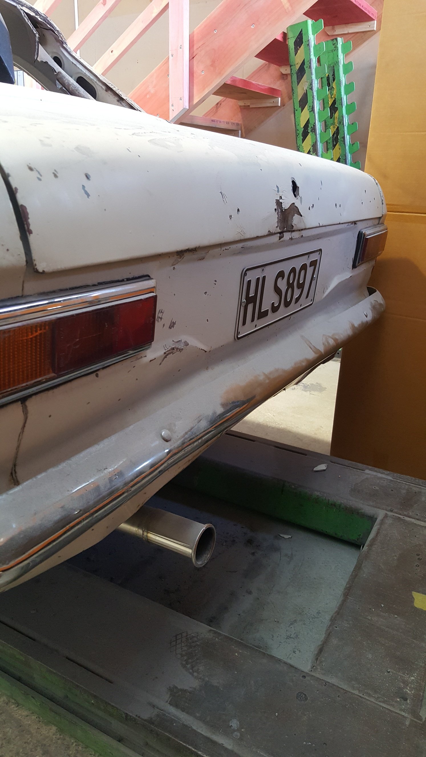
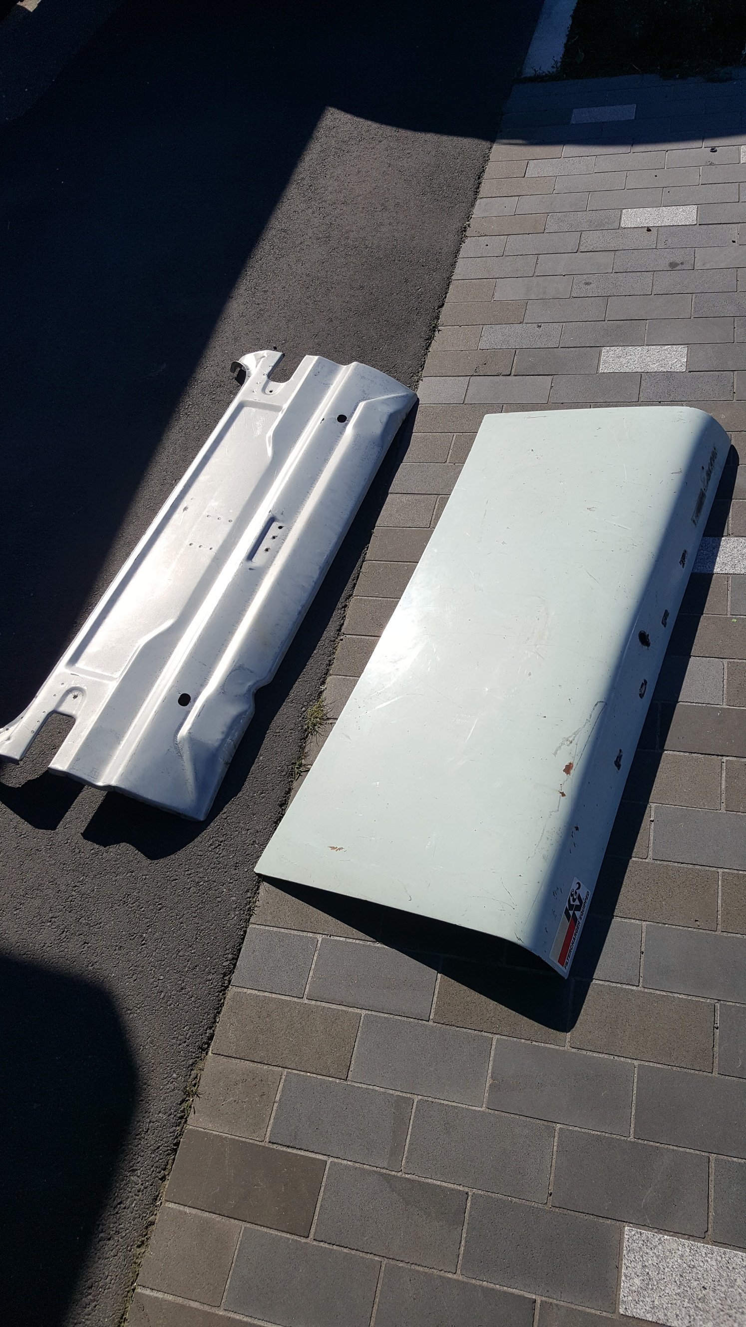
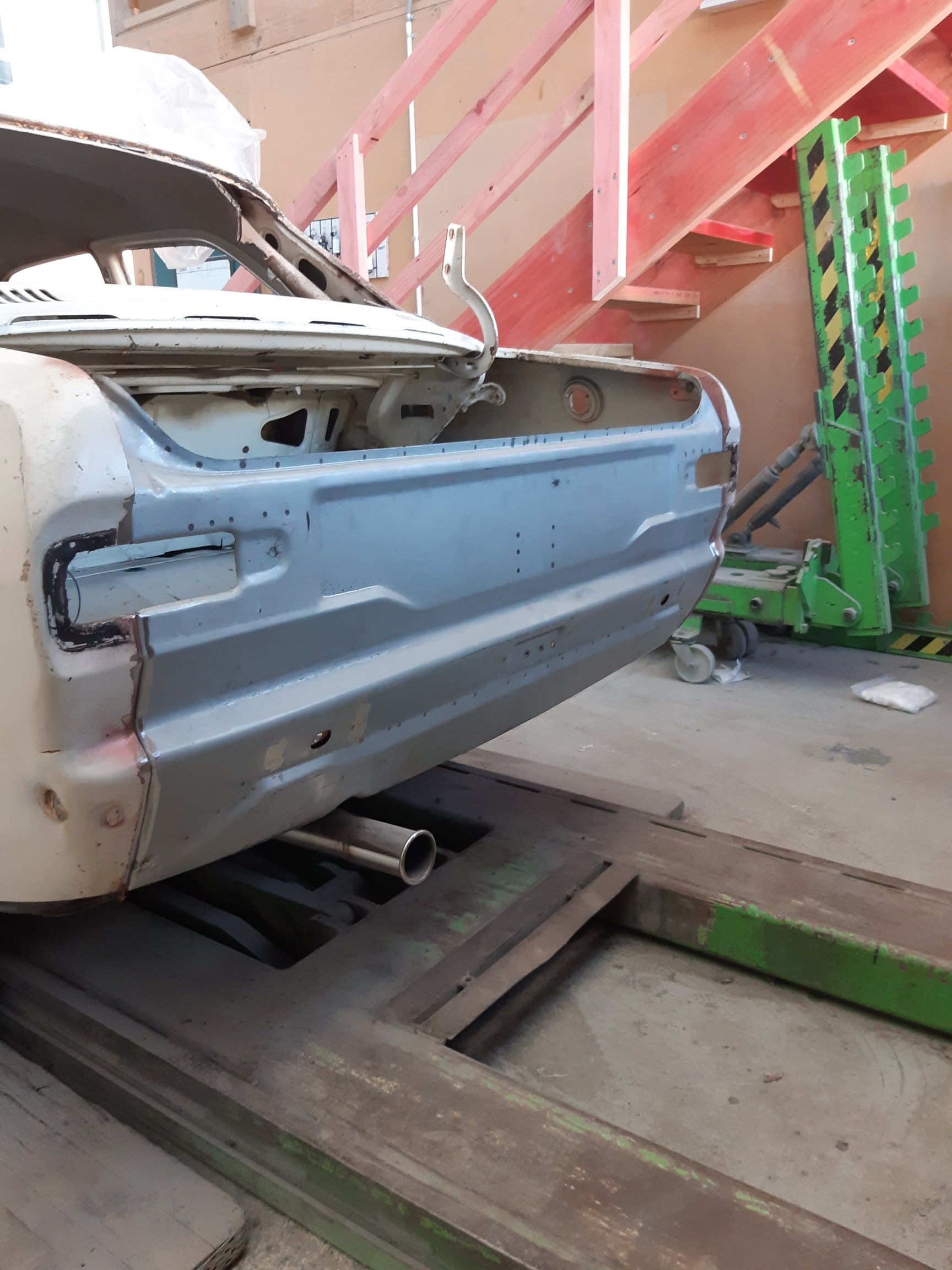
So the rear panel between the tail lights has had a shunt. The boot has also been pushed in aswell. So i managed to find another boot lid and went Palmside for more panels So i left it with my panel beater to sort out. He had to sort a few rust spots. Panel fitted.
- 27 replies
-
- 14
-

-
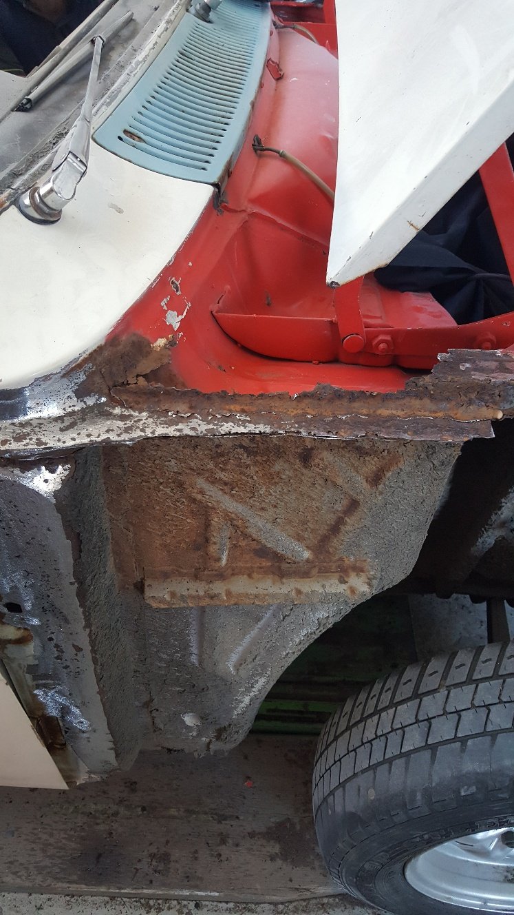
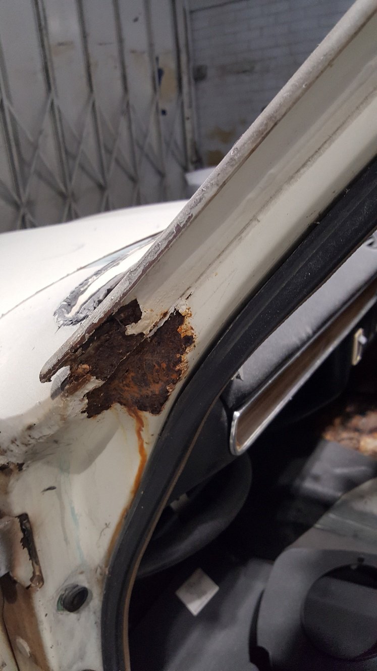
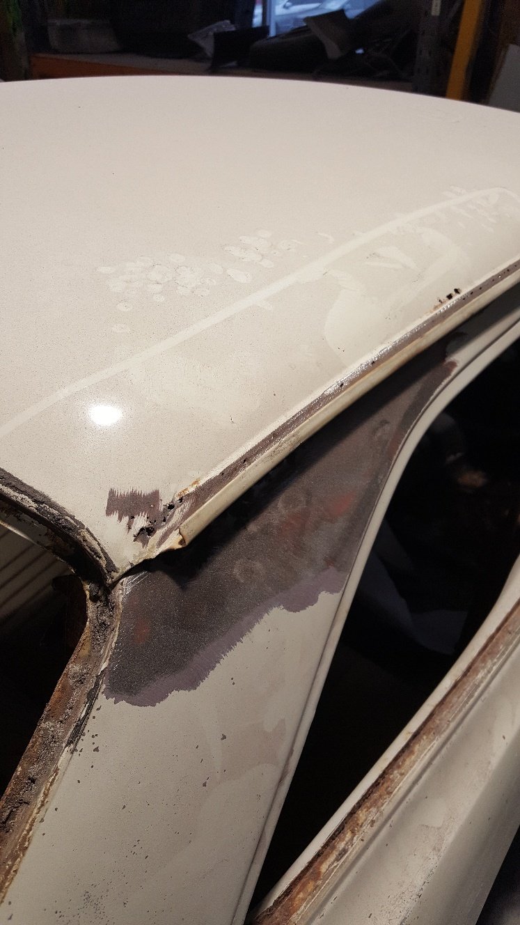
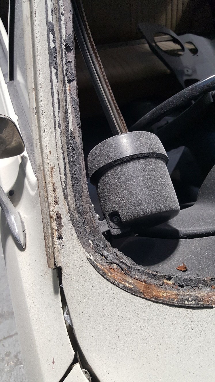
So it's been a while since i dropped the escort off at the panel beaters, but there has been some progress lately. Here's a few shots of the rust thats to be addressed. At this point my panel beater has suggested to fit a new roof skin.
- 27 replies
-
- 10
-
-
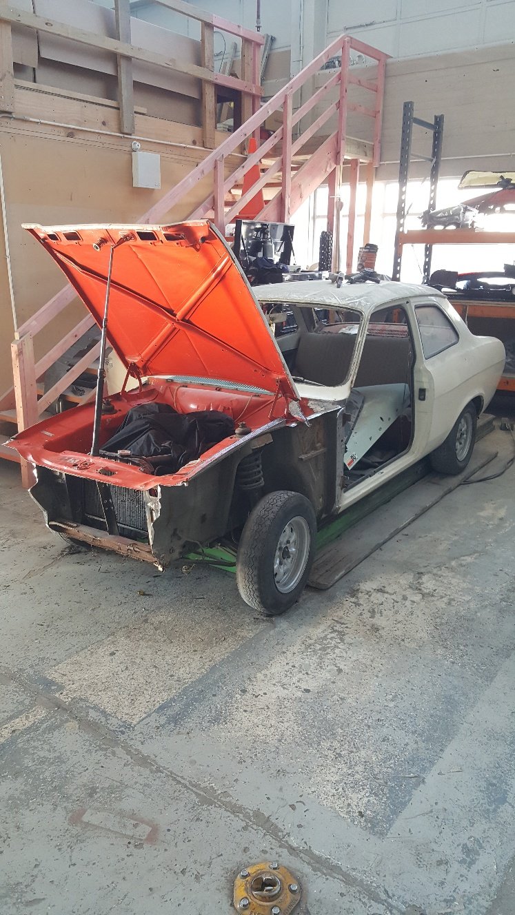
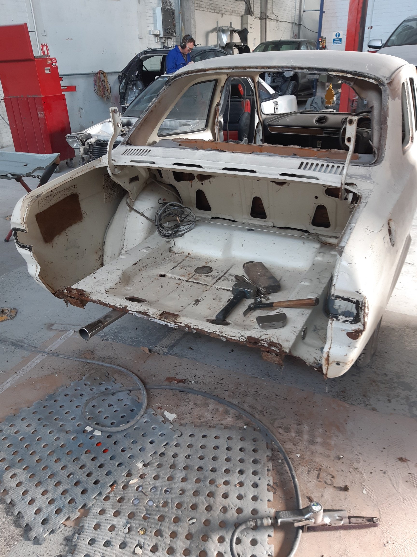
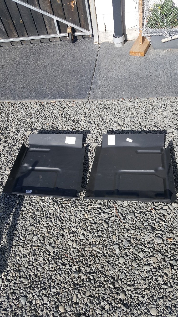
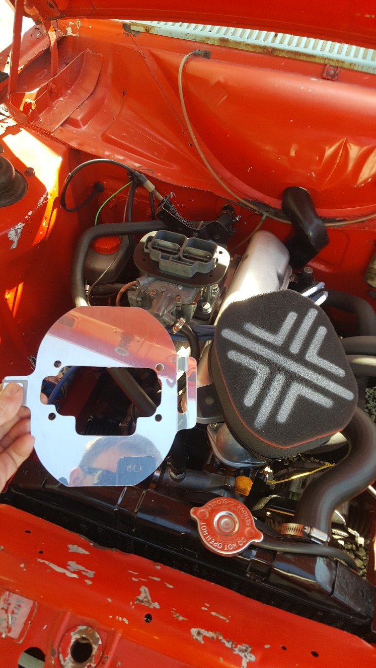
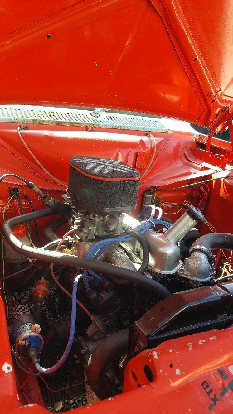
Finished result. Bumper on the right is the one that has just been re chromed. Also with the virus stopping work my escort is off to get its rust cut out. I have built a engine for a chap that is sorting my rust in return. He's not working so he said if I can get it to him he'd have a crack at the rust over the next 4 weeks. So I shoot into palmside for a front panel and some new front floor panels. Also bought a Pipercross air cleaner while I was at Palmside. Escort loaded up. Once I dropped it off I removed the passenger door. It has a few creases in it so I have a project to keep me entertained trying to straighten that out. I also have to fit new guards to my car transporter. I mounted the set on it at the moment too close. So the next set will have more clearance, but I still want to be able to open the doors of the vehicle once loaded.
-
I bought some quarter bumpers two from the back of a van so they where both just painted. I rung around trying to find out how much it was going to cost to re chrome them. I had some over the phone quotes of around $300-$350 so when the chap that sold me the two van rear bumpers had a single chromed bumper for $40 i jumped on it. Then id only need to get one of my van unchromed bumpers chromed. Here's a pic of one of the painted fear van bumpers So I put the van bumper in our acid bath at work and whiched stripped the paint off. It had a small crease in it where the bumper bracket had been pushed into it. So I hammered that out the best I could. I then took this down to Christchurch Metal Finishers and was surprised when I was only quoted $40 to re chrome this. The reason for it being cheaper than my phone quotes was that it didn't need to be de chromed and was prepped and ready to go straight in the baths.
-
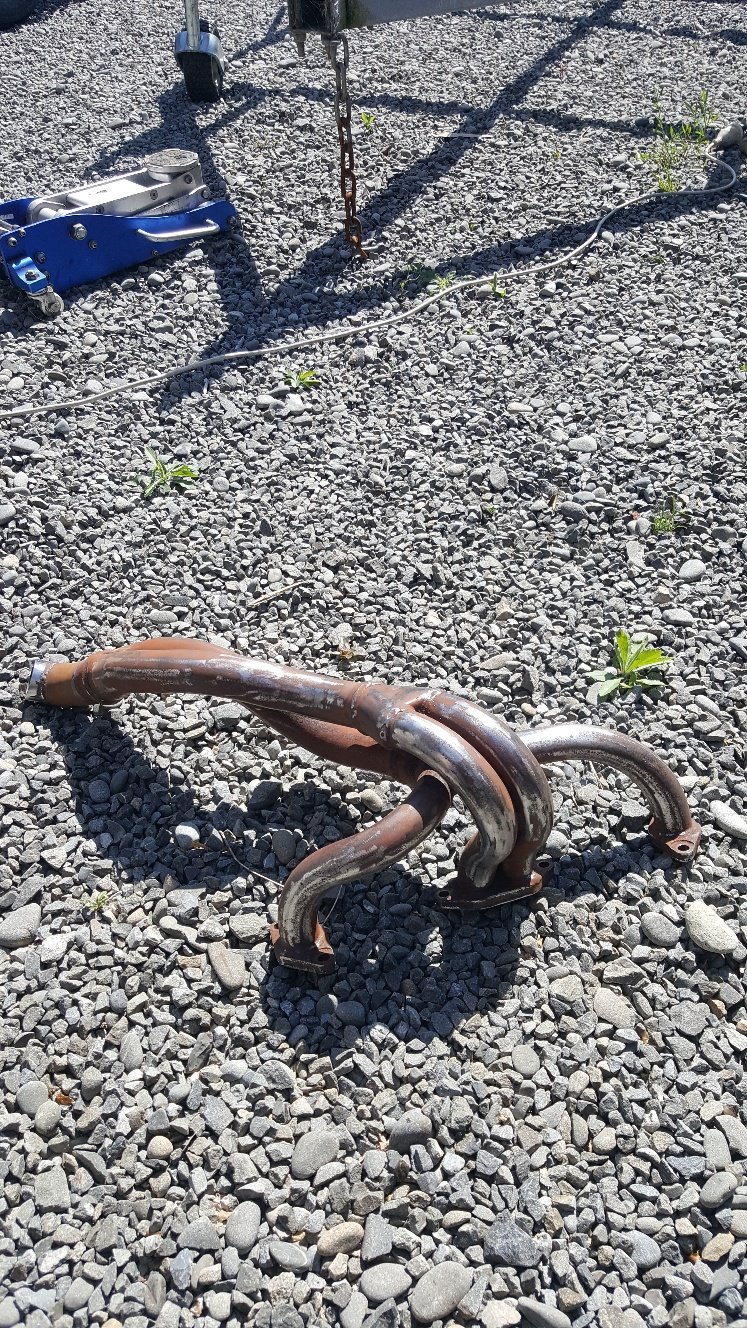
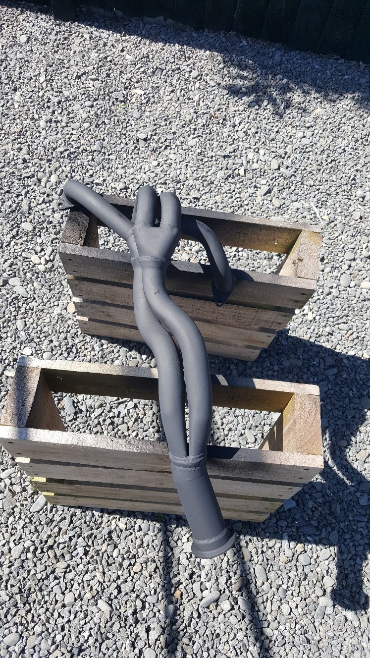
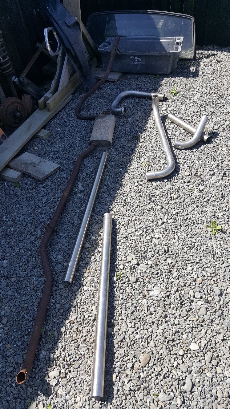
So started by cutting up a few 90degree bends. Then started to try replicate the orginal exhaust so the new exhaust will run in a similar path. Was intending on making some headers. But just decided to clean up the old factory headers for now. Coat of exhaust paint. Finished
- 27 replies
-
- 17
-
-
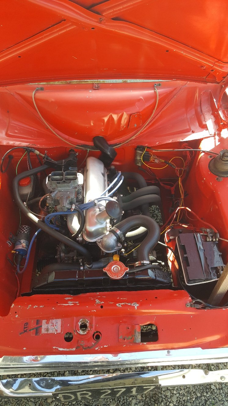
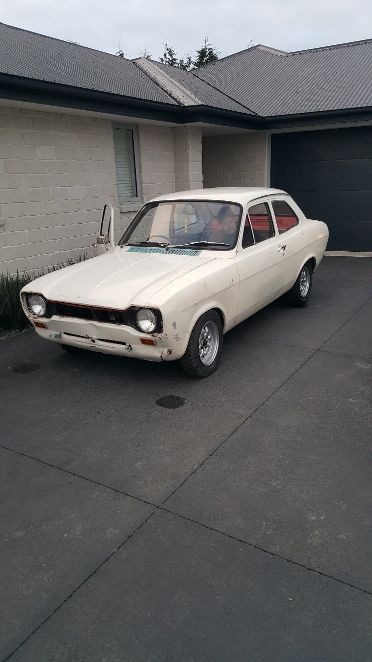
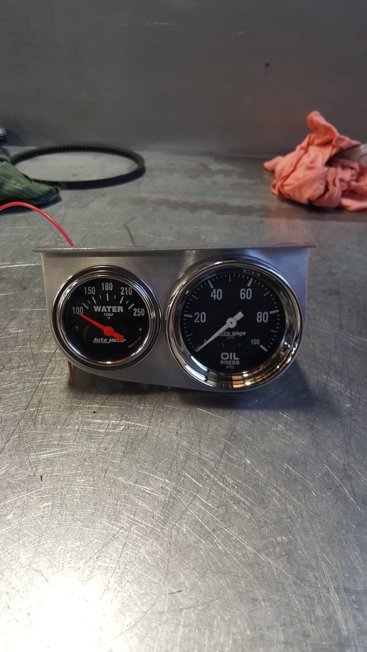
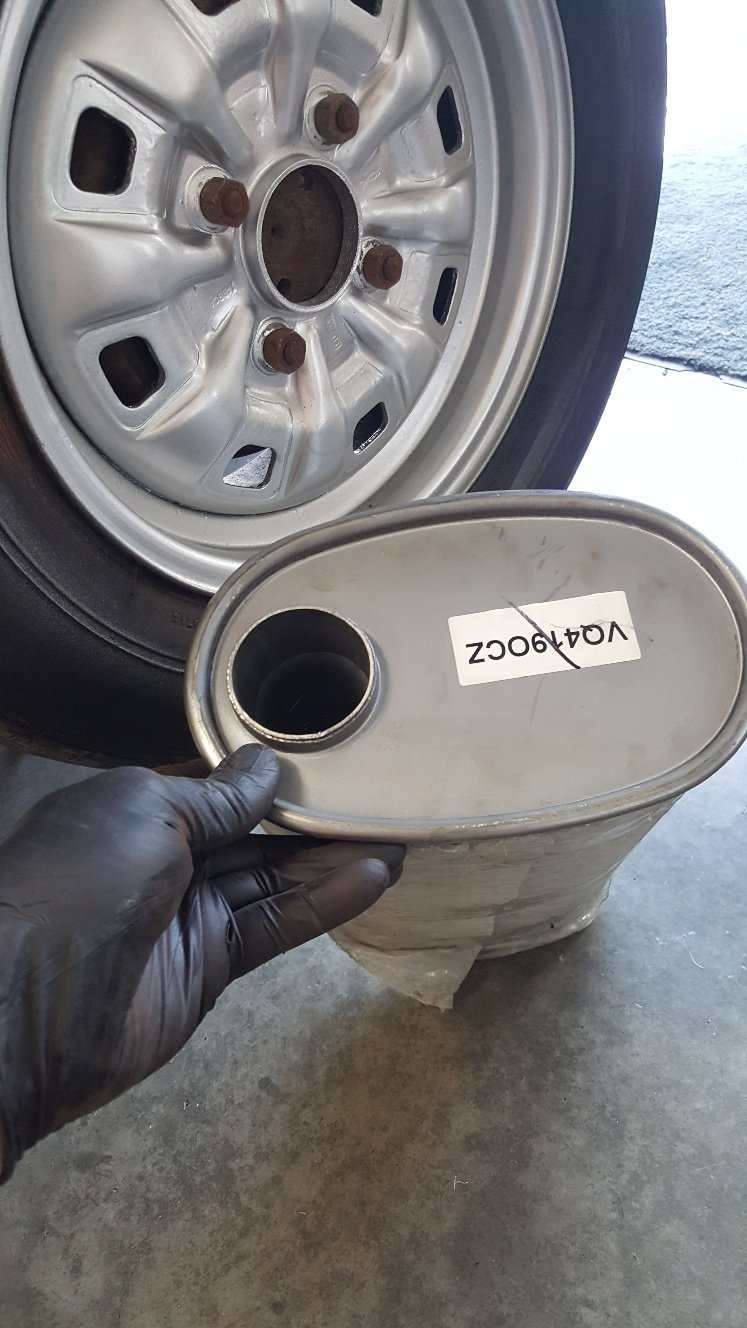
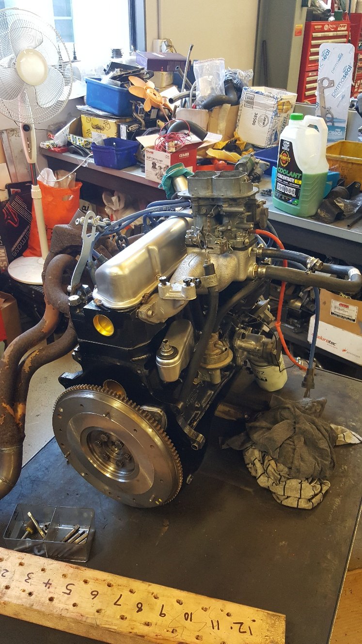
So I've fitted the engine here's a picture of it about to go on its maiden voyage. So I don't have a exhaust on it other than the orginal sport headers. So I thought it's time to sort the exhaust. So I bought a muffler and some V bands. I also made a bracket for a couple of gauges. Here's a shot of the orginal exhaust on the left and some stainless 2inch pipe I bought of my old work mate that owns a metal recyclers now. If you want cheap stainless pipe for a exhaust scrap yard is where to go.
- 27 replies
-
- 14
-
-

-
Yes im trying to keep it cheap distributor and carb wise. Im possibly thinking of EFI in the future some time after getting it reregistered. But the Bluetooth mapable units sound good. Also a bigger cam would bleed off some compression at lower rpm. But will just try the regraphed dizzy for know. Which im sure ill probably regret and wish I spent more on a decent unit.
-
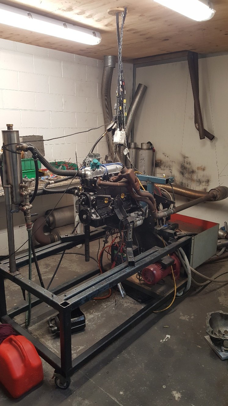
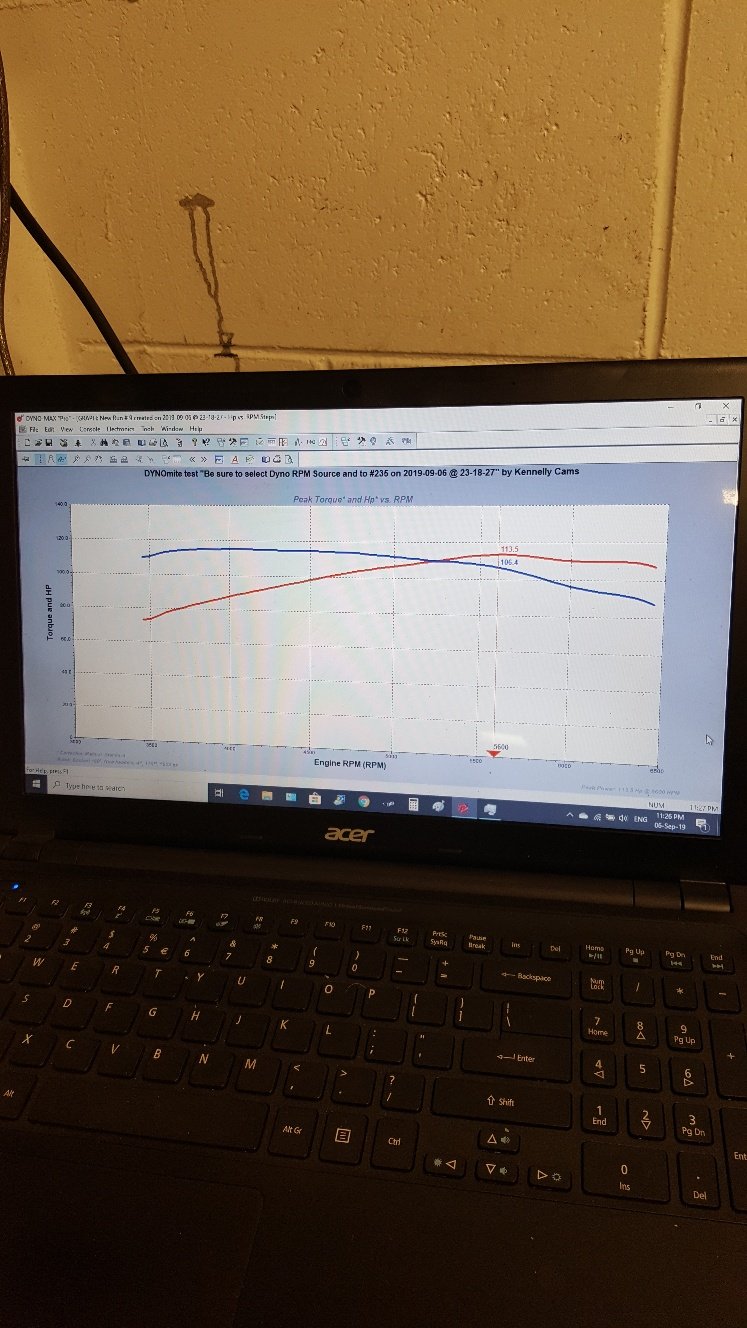
Yes id say some sidedraphts would definitely help out. The cam is pretty small aswel not much bigger than a GT spec, so I wasn't expecting to much power. But was hoping to hit 120hp it tips over really early so it will never make a good dyno number. 113hp 5500 rpm will have to do for now. I need to get the distributor regraphed cause the high comp and small cam make it det at lower rpm. I don't know much about the factory sport 4-2-1 headers, but I imagine they may be on the small side primary size wise. If anyone has any experience with them it would be interesting to here.
-
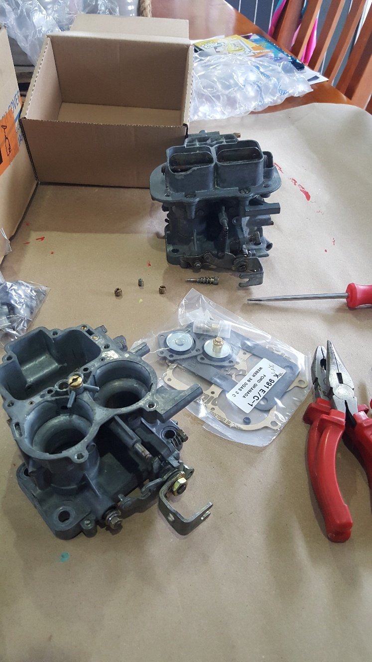
Took the gearbox into work and gave it A good clean out. Then onto putting new gaskets through the 32/36 Weber I'd bought a few months back. I made one carb from two. Then fitted carb and manifold up. Found the old exhaust headers that came with the car and bolted them up. Then I took it down to Kennelly Cams to run it up on the dyno. Run it up and found air fuel ratio weren't to far away. The distributor was pretty average and the mechanical advance was coming in at 2000rpm so with the high comp it was det monster. So we backed of the static timing a bit and ran it up. It made a whopping 113hp. So I was a little disappointed. I was hoping to crack 120hp but apparently the intake manifold is the main reason for holding it back. The cam is pretty small so it was never going to make a big amount of power. With good low down torque it should drive nice.
- 27 replies
-
- 15
-
-
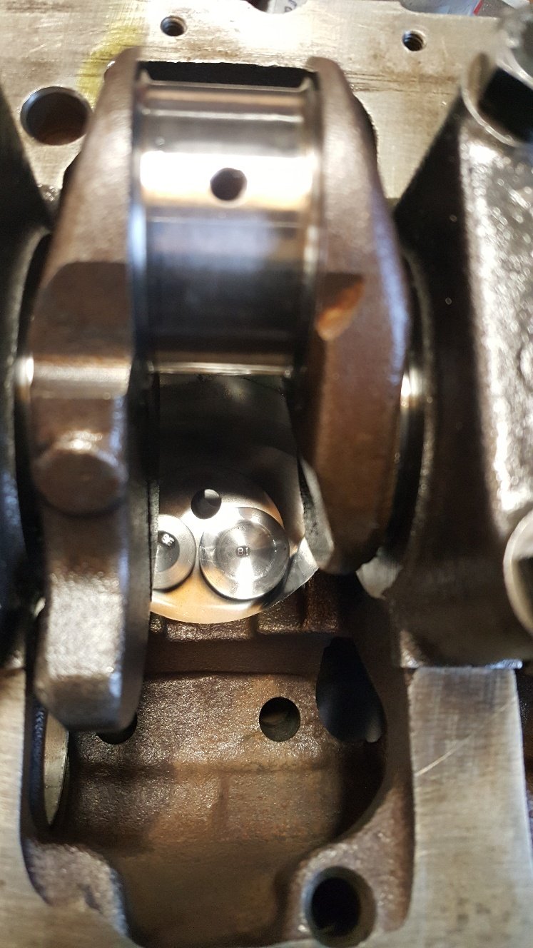
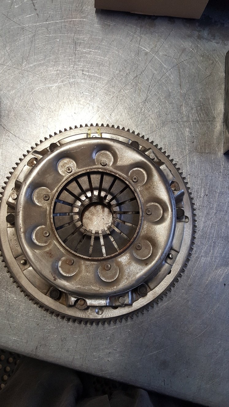
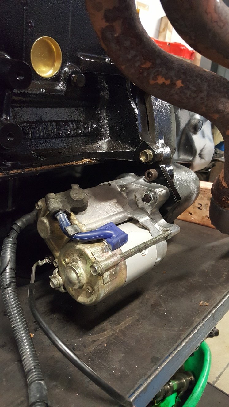
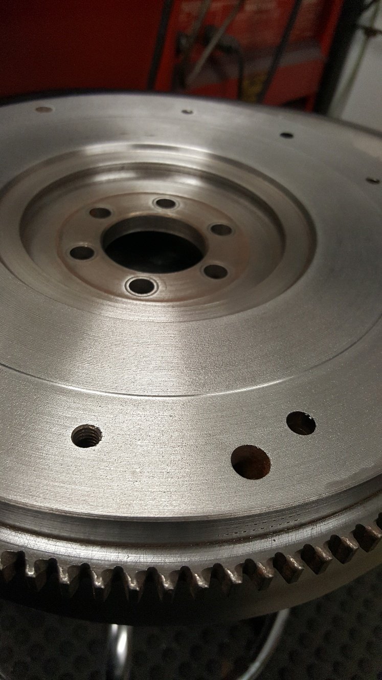
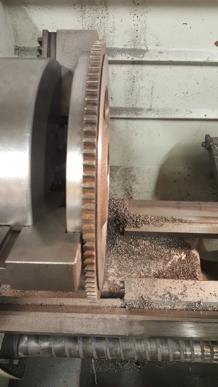
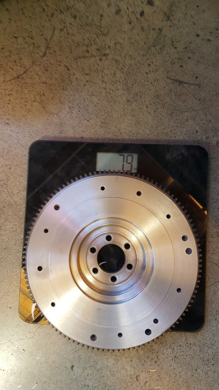
You can see at 6 o'clock on the the flywheel there's a small hole drilled into the the flywheel to remove weight and also the clutch cover has had a small amount sanded off it in the same area. Flywheel torqued up. Here's a starter motor adapter that I've had lying around for years. Drilled it for the Honda starter motor and gave it A lick of paint. Starter motor fitted
-
Sorry I am very average at sorting my thread. Valiant made a discussion page up first but I didn't put the link into my project thread till just recently. Yoeddy thanks for sorting the second discussion page and sorry for the confusion. Sorry I cant get any pics of the balancing but I imagine if you search Sunnen engine balancing or Hinds engine balancing you may be able to find something.
-
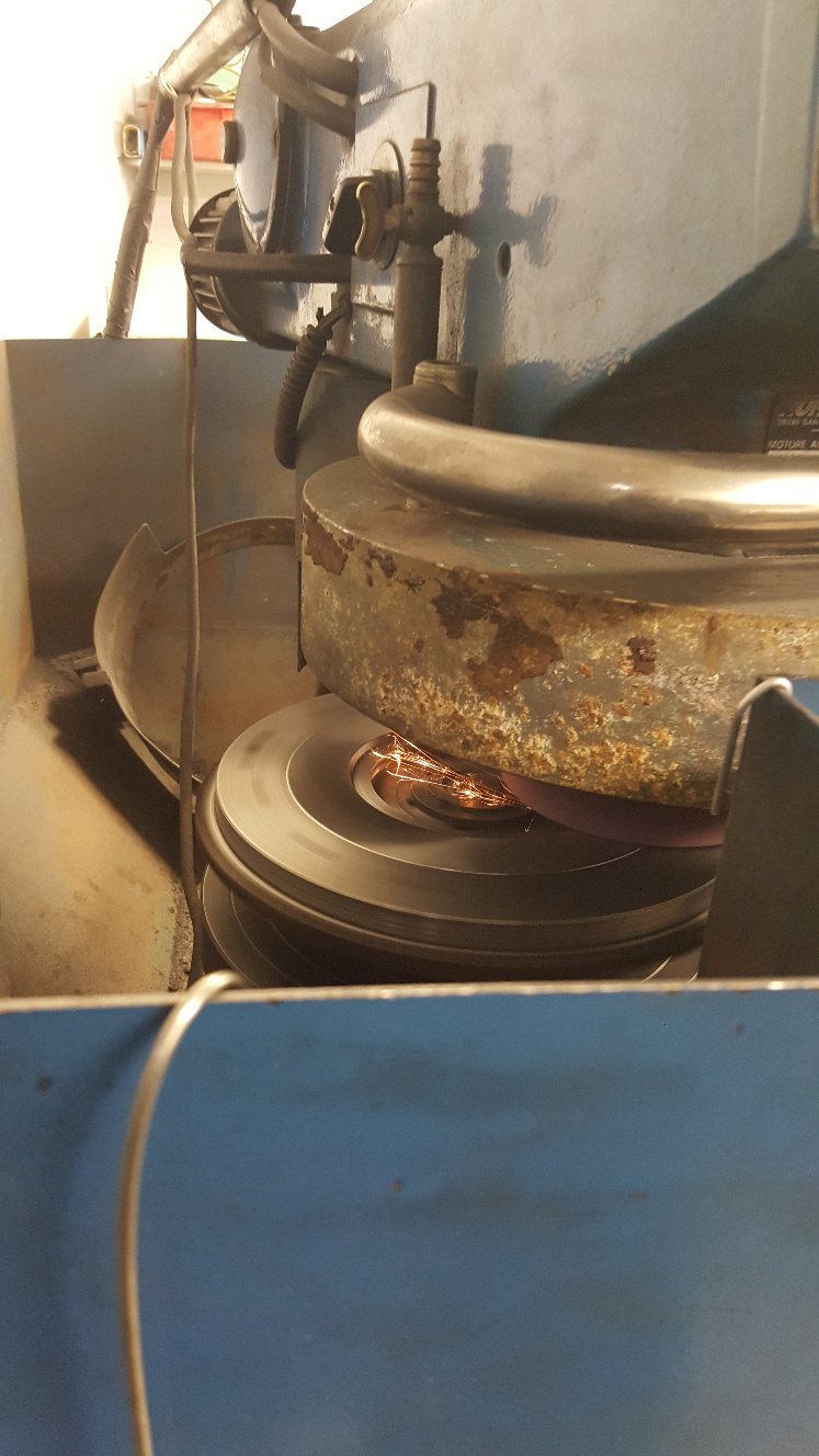
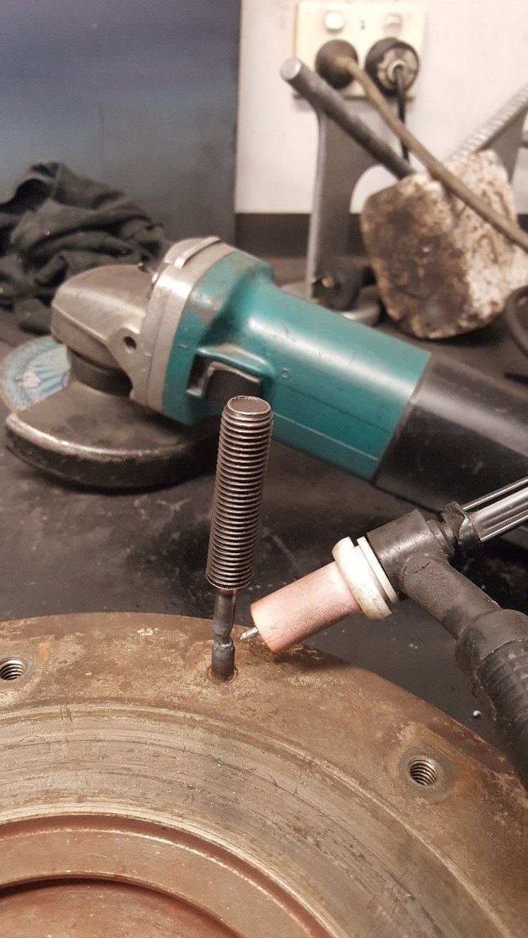
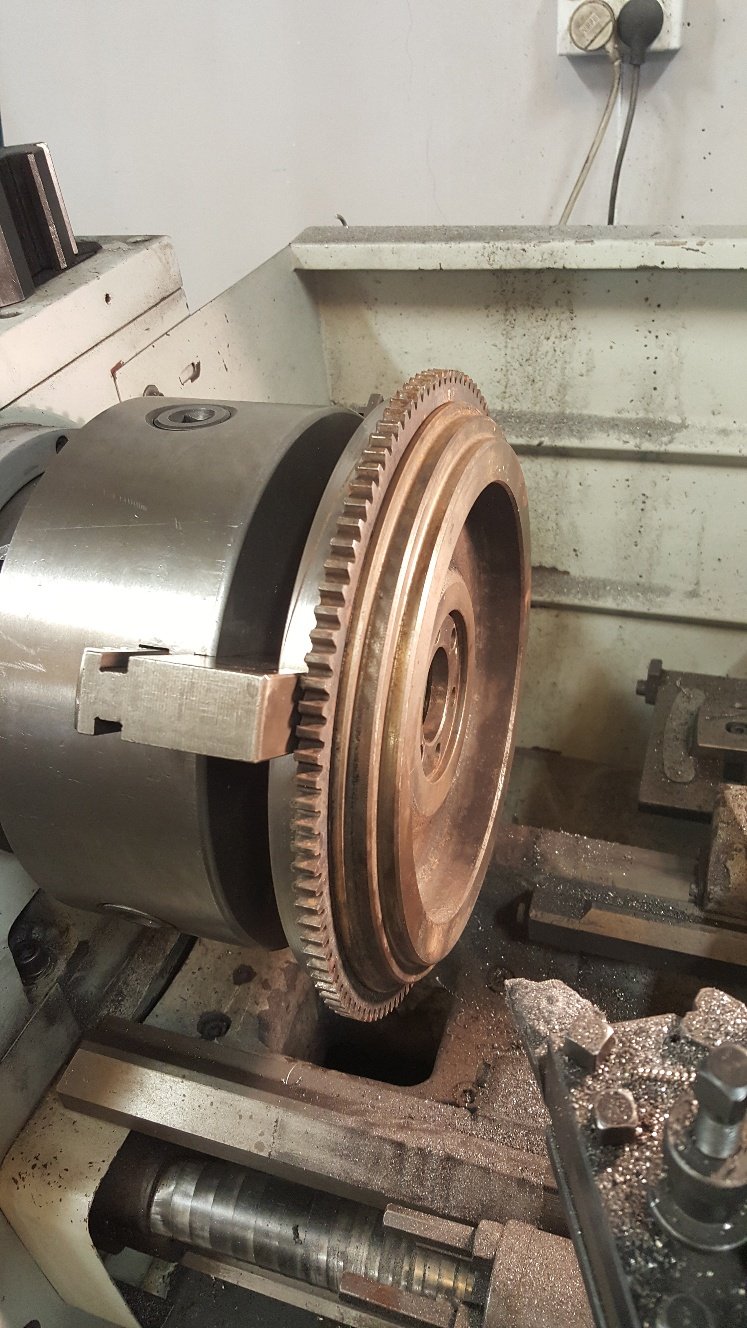
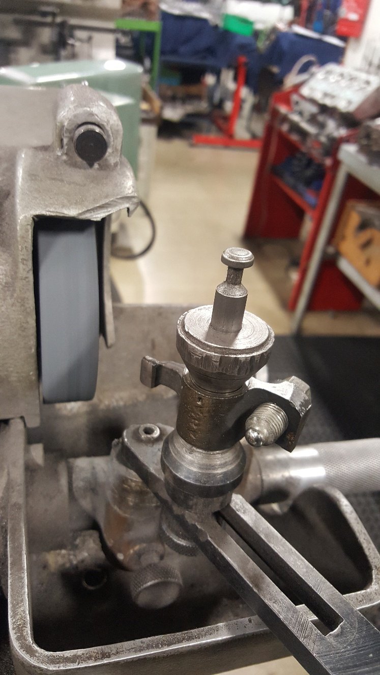
Here's a better shot of the .5mm step This is our flywheel grinder The flywheel get mounted to the round turn table. Then the grinder head swings to the left and you wind the grinder head down onto the flywheel. All sorted and ready to go off for a balance. We don't have a balancer so we use another reconditioner for balancing and he uses us for crank grinding. There's some machines that arnt viable to own as you may only use them a couple of times a week.
- 27 replies
-
- 11
-
-
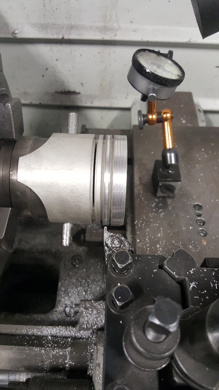
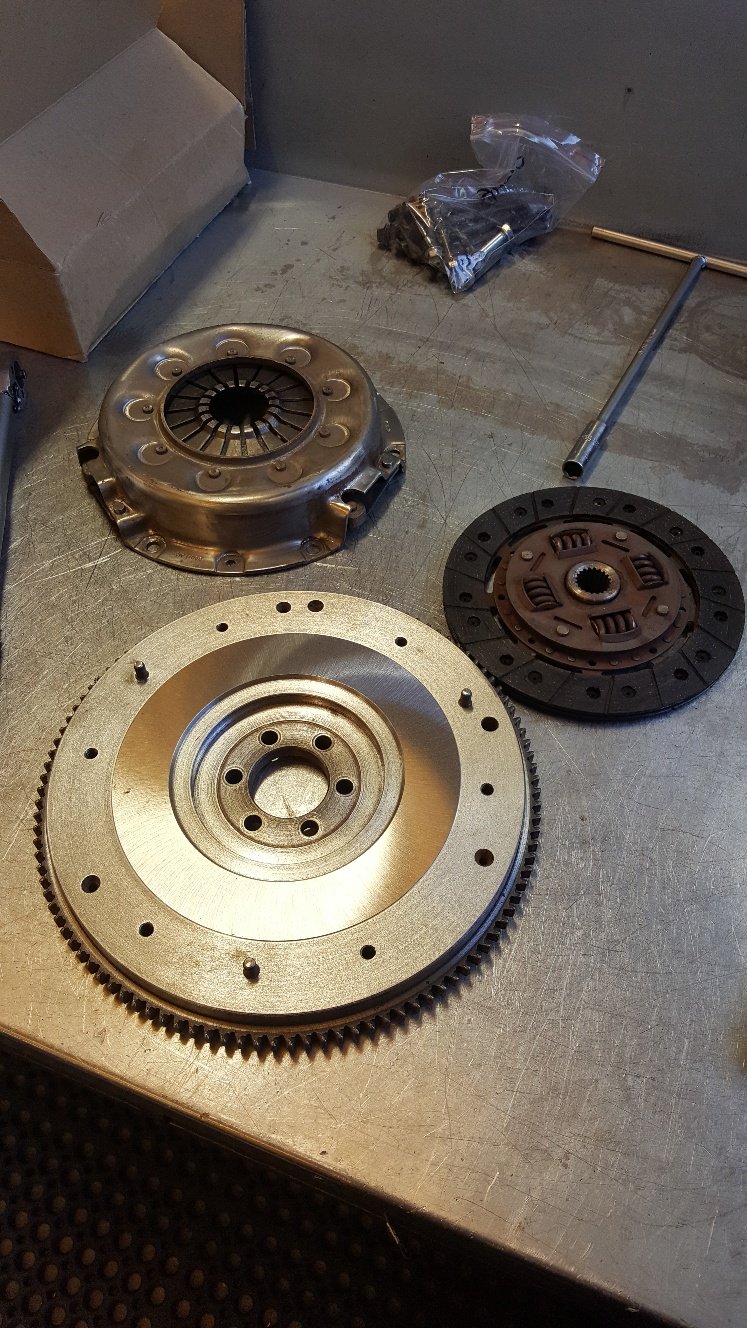
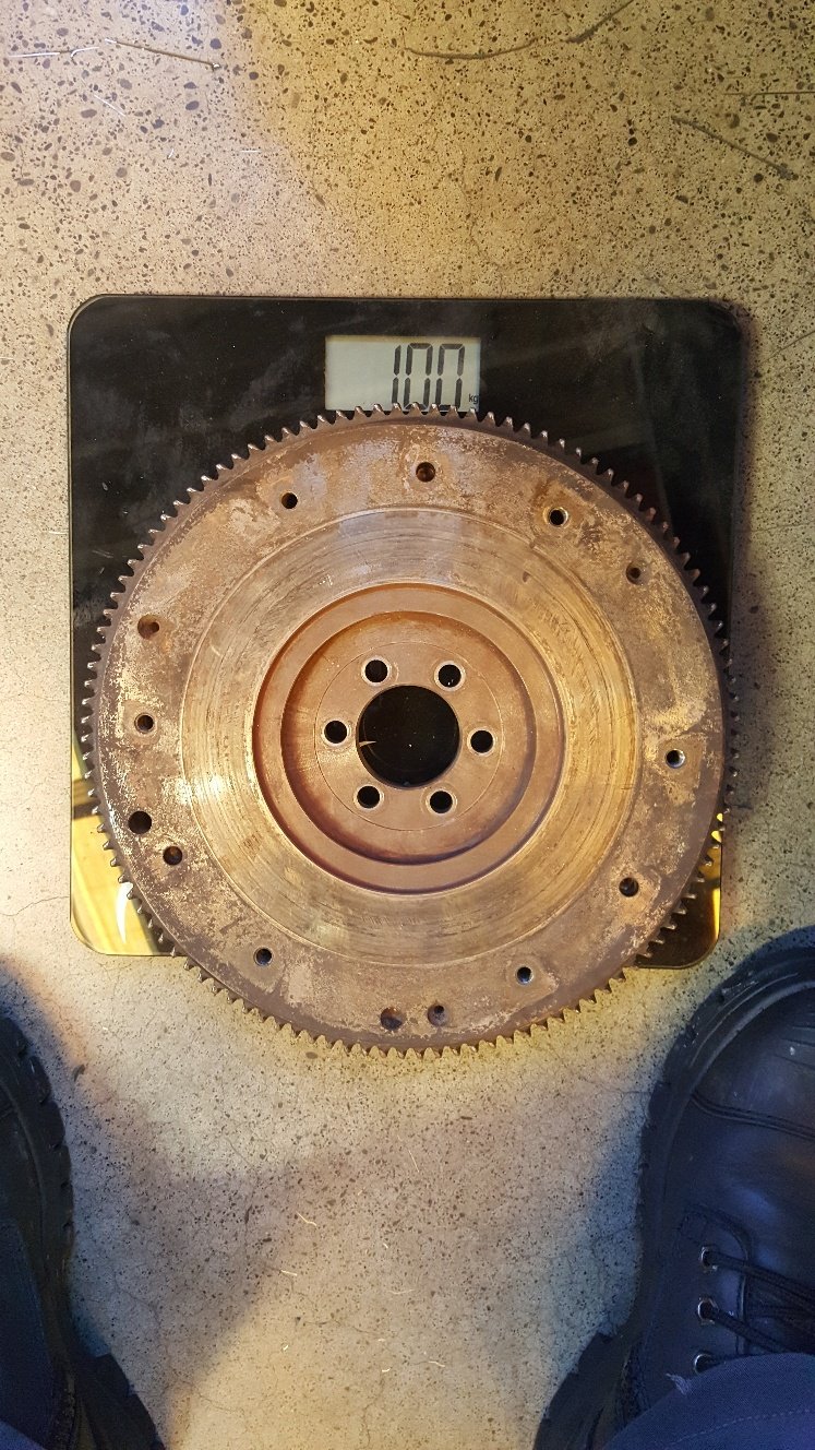
On to the flywheel. First remove the dowels Weld a stud to the dowels to attach the slide puller. Weigh it. Into the lathe. Sorted. I also machined the face in the lathe. I machined the outside area where the pressure plate clamps down .5mm to give the pressure plate more clamping load. Weighed it after.
- 27 replies
-
- 18
-
-
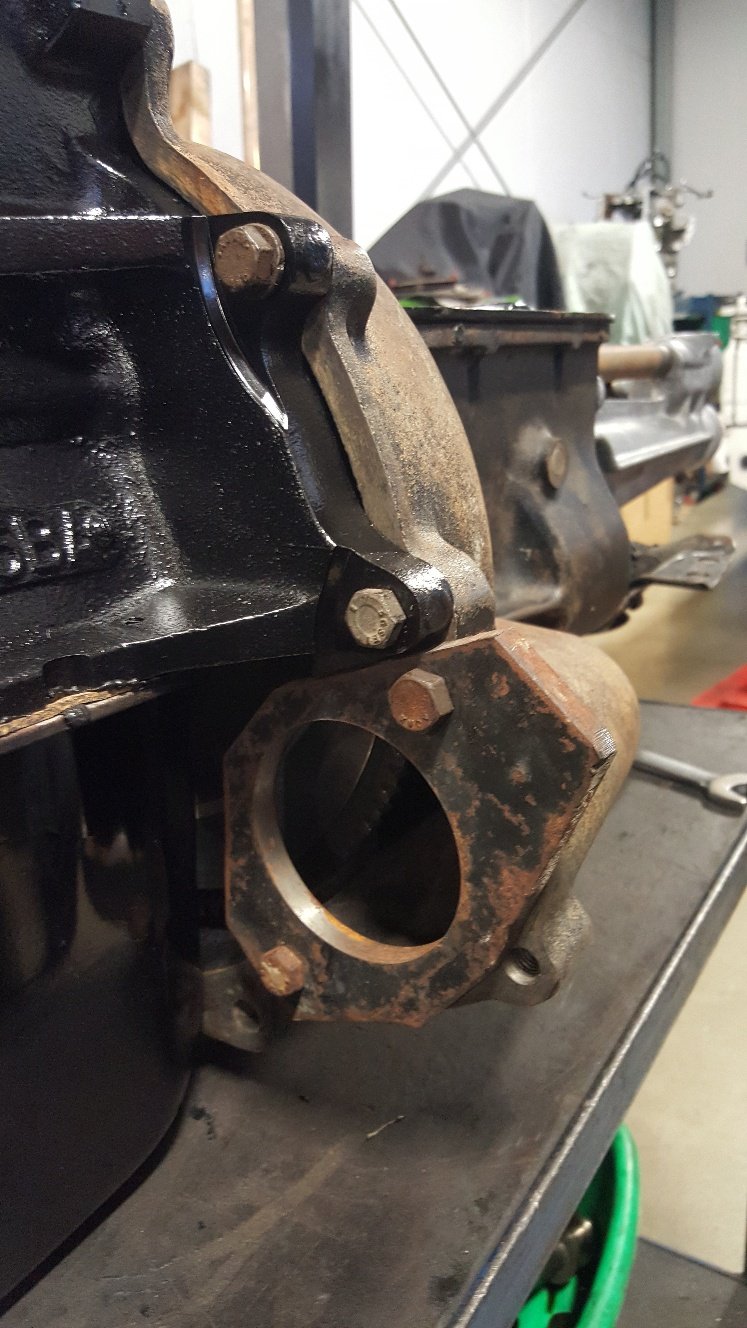
So Al my work mate was good enough to give the intake manifold a bit of a tidy up with the die grinder while I was assembling the engine With getting the engine pretty much together I thought it was time to get onto a few of the bolt on items. I know from my mk1 cortina that I was wasting my time the orginal alternator. So I found a old Nissan alternator and fitted that. Redrilled the holes and it pretty much lined up. Changed the pulley over from the old Lucas alternator. Which just ment turning the hole out to suit the Nissan alternator. So it's pretty much together just have to sort the flywheel out next.
- 27 replies
-
- 21
-
-
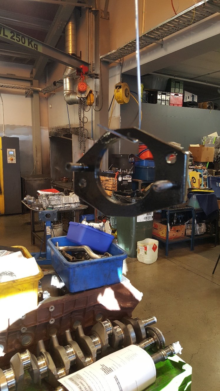
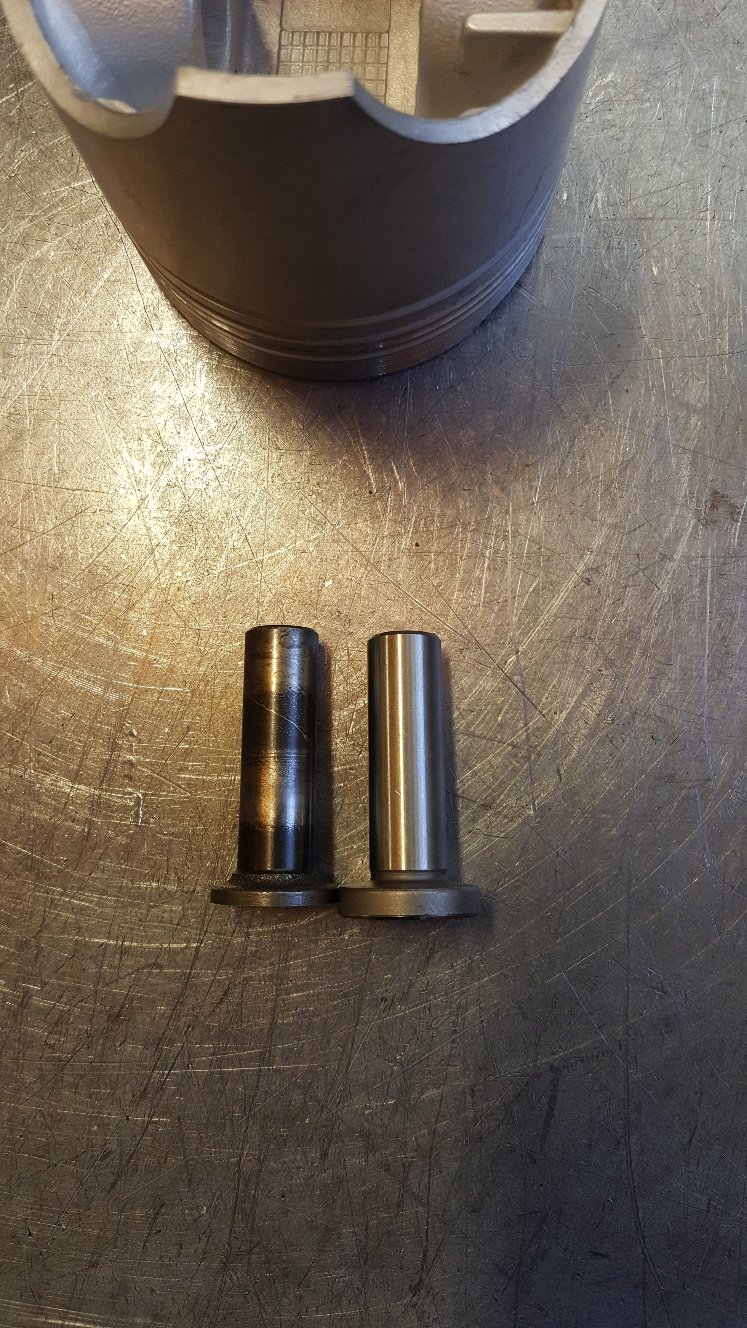
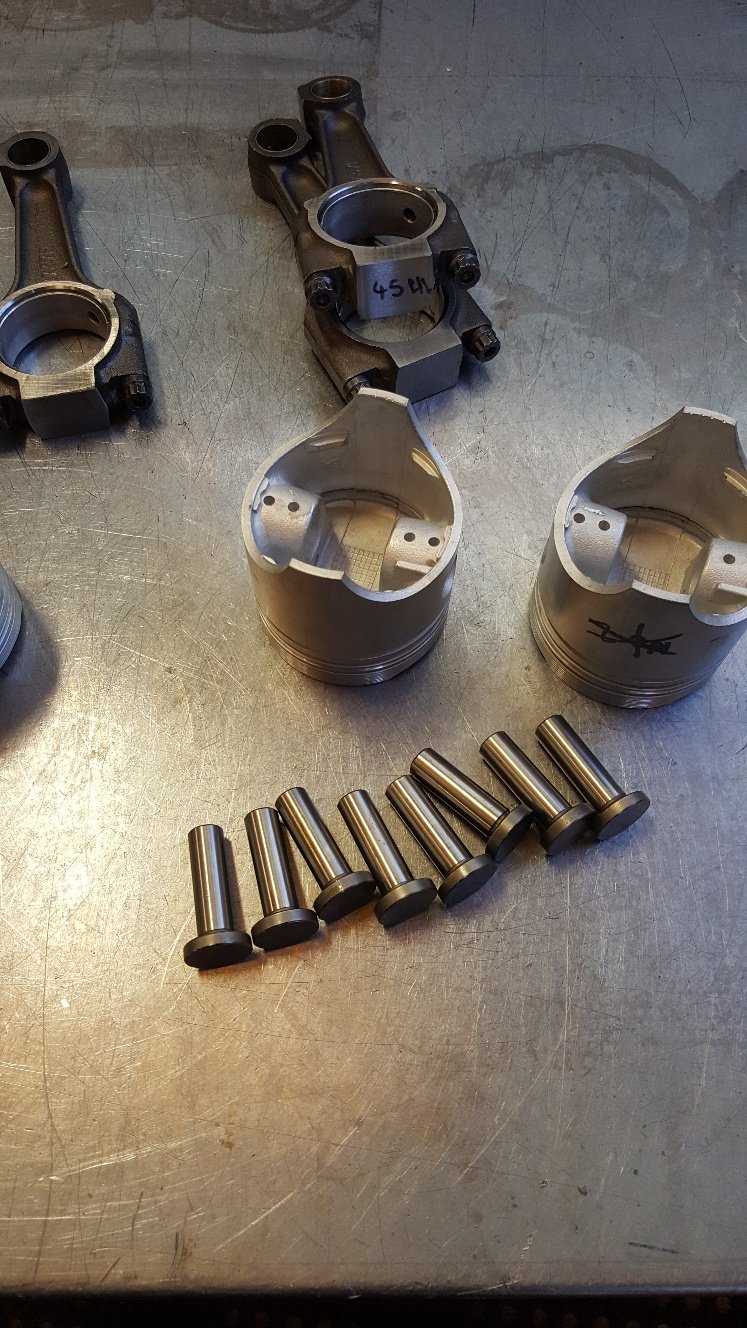
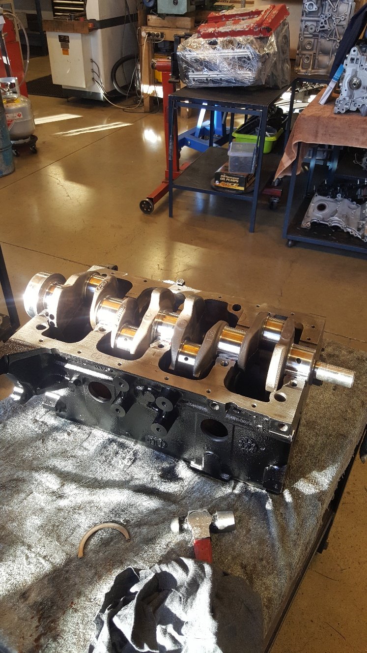
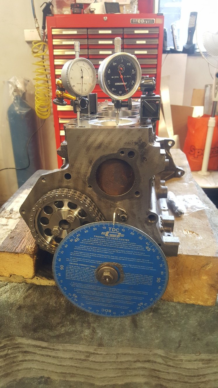
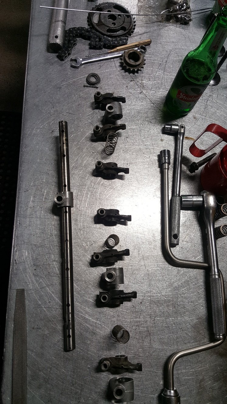
Time for final assembly. I bought a new set of cam followers as the old ones look a bit thin in the head. And I have had one break in another engine. Put the crank in. Short blocked. Checked the front pulley for tdc. It's the best time to check it. Not a common problem with solid front pulleys. But definitely common for old harmonic balancers to move and cause a headache when timing your engine. Assembled the head.
- 27 replies
-
- 18
-
-
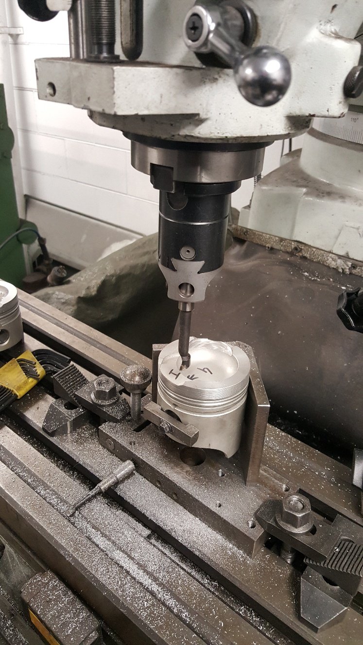
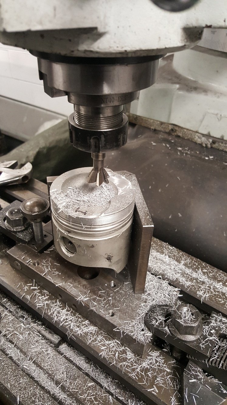
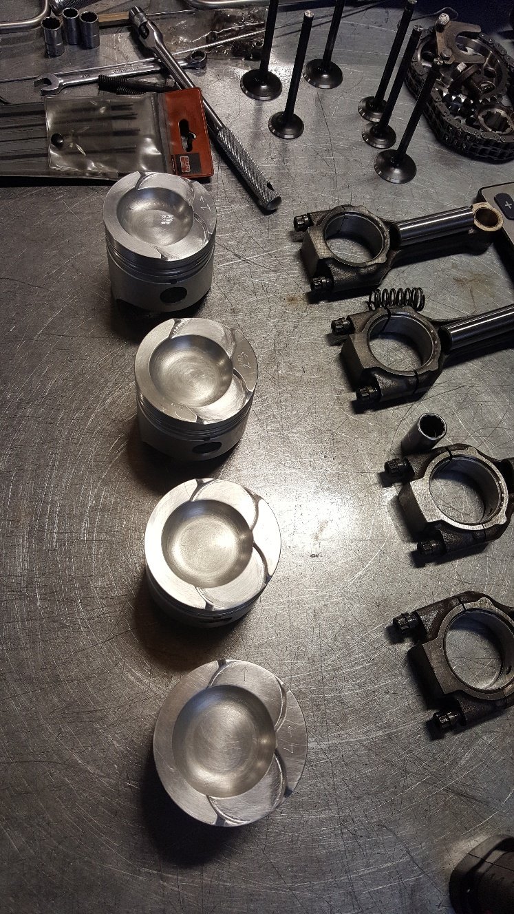
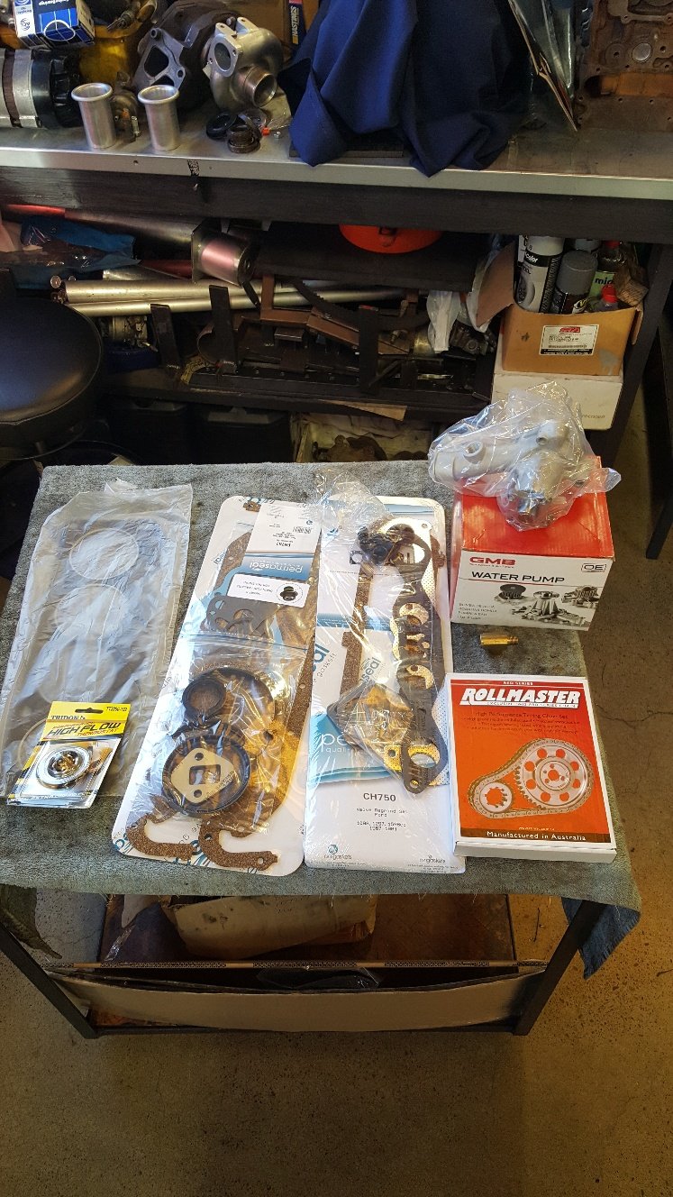
So now I know I definitely need to make the intake valve pockets bigger OD wise by 2mm. Which was no surprise as I've increased the valve size a good amount. I also found I need to deepen the exhaust pocket by 1mm. So I used a the mill to machine the pistons. We normally use a guy to do our valve pockets as we don't really have the gear to do a really nice job of it. But I'm doing this on a budget so I had a crack. This the tooling I used to take the OD out. Above And this for deepening. They came out ok. But we would normally out work this job. I gave them a tidy up with wet and dry and a small file. Tried to take the sharp edges off the top of the piston. Here's a pic of a few parts. I wasn't going spend $250 on the double row cam chain gear kit. But it had to happen.
- 27 replies
-
- 17
-
-
Hi thanks for the kind word. Yes its not cheap to recondition a engine, so just trying to give some context into the time that goes into machining and building a engine. I wasn't sure how much info to add as I didn't want it to drag on. I have fitted valve seat inserts for unleaded fuel. P.S I really enjoyed your housetruck build and all your other builds
-
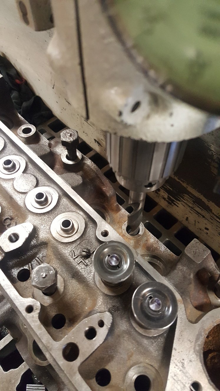
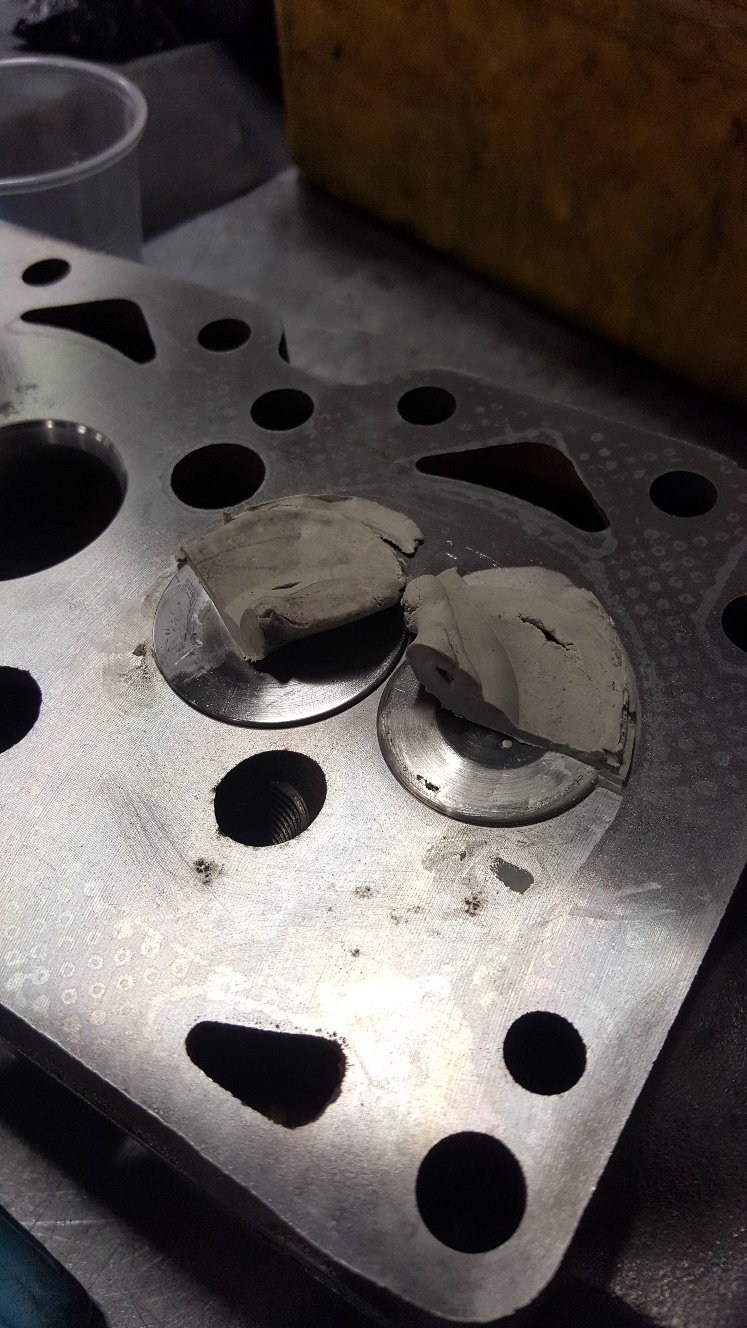
With the head sorted i can put the camshaft in and check piston to valve clearance. But first I need to dowel the head to the block. These old beast come from the factory without any location other than the head bolts. So I center off one of the head bolt holes and drilled it to 14mm. Then bolt the head one without moving anything and drill the head bolt hole out to 14mm. Then fit the head on the dowel and drill the other head bolt hole for the second dowl. So dialed the cam in. Then bolted the head on and found my rockers where a little worn so gave them a tidy up. Forgot to take pictures of the head fitted. But basically fitted the head, put two layers of plastersene on top of the piston in the valve cut outs. Then turned the engine over to get the valves to in print into the plaster. Then I cut half the plaster away to see how thick it is. This gives you a good indication of the piston to valve clearance.
- 27 replies
-
- 16
-
-
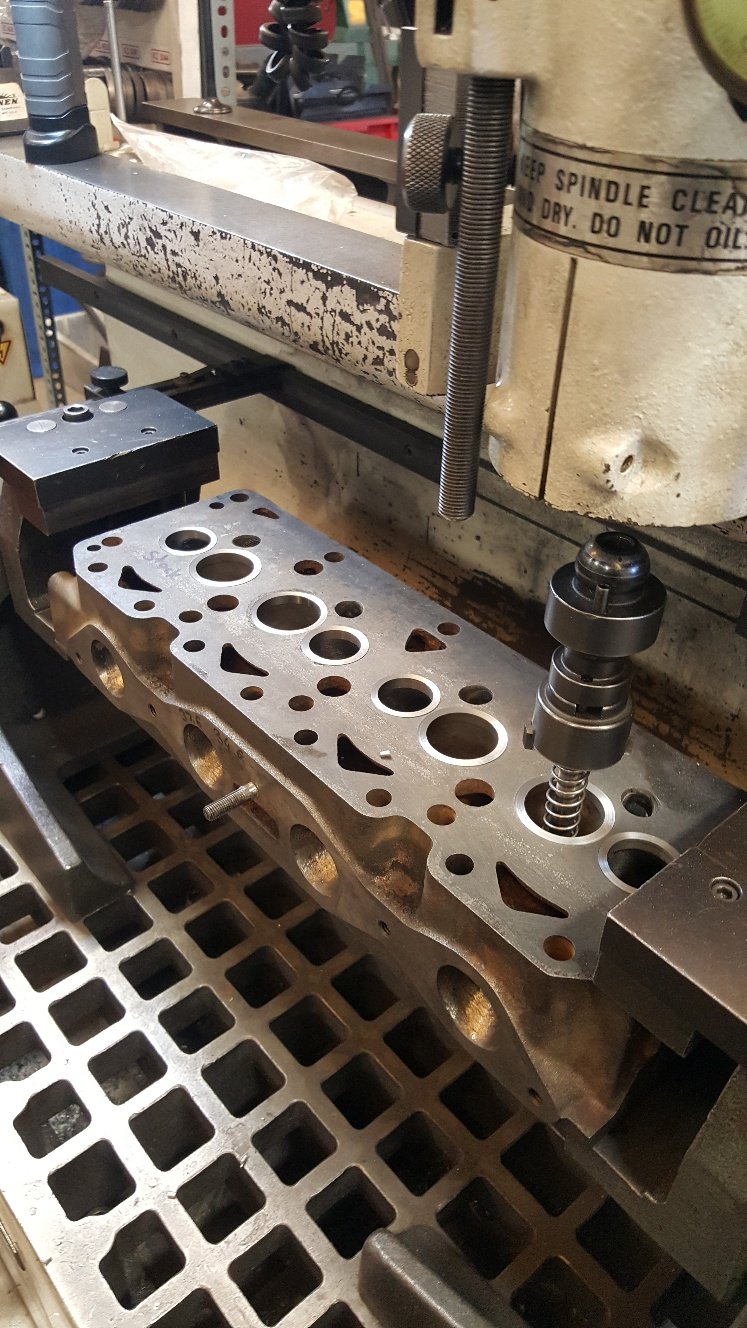
I'm happy with the valve size. So I cut seats into the new valve inserts. I cut all the seats as close to the same height as possible. Al my work mate had done some research into the best seat angles, and we used a radius throat cutter profile. Once they are all cut to the right depth and right size to get the 45degree seating where we want it on the valve face we are ready to synchro seat the seats with the stone gear. We believe this gives a good sealing finish on the seats. I didn't get any pictures of this, but basically you face the valve seat grinding stone on the valve facer to get the same exact angle. Here's a picture of me stoning the seat. You can see the seats are polished up. I now check to see if they are seating the whole width on the valve face. I didn't get a picture of this. But we use a engineers blue to wipe on the valve the put the valve into the head and push the valve onto the seat and look to see if the engineers blue makes full contact from the valve to the seat. So the valve and seats are done. So I need some valve springs so I went down to Kennelly Cams to see PK and Adam. They have a good selection of springs in stock. This is also where I got my cam reground. So running the FE Mazda valves I need to use a different valve spring retainer to the stock xflow item. I looked at using the FE retainers but unfortunately that was going to make my spring install height to tight. The spring install height is the measurement from the spring seat on the head to the valve spring retainer. Stock xflow is around 33mm. So that's what I'm trying to get close to. So Al grabbed a Toyota 1kz retainer and we took a measurement and they looked like they would do the job with a bit of turning in the lathe. You can see the spring isn't sitting in the right spot. So I made a arbor to spin the retainers in the lathe Finished retainers sitting on the spring.
- 27 replies
-
- 19
-
-
I modified my 1uz sump a while back. I welded it bolted to the block and it still warped. I found bolting it back to the block and putting feller blades between the block and sump in strategic places and tightening it down to try and bend it back, then using a gas torch to heat the sump to relieve the tension. It took a few attempts to get it back close. Then I machined the last mm or so out.
-
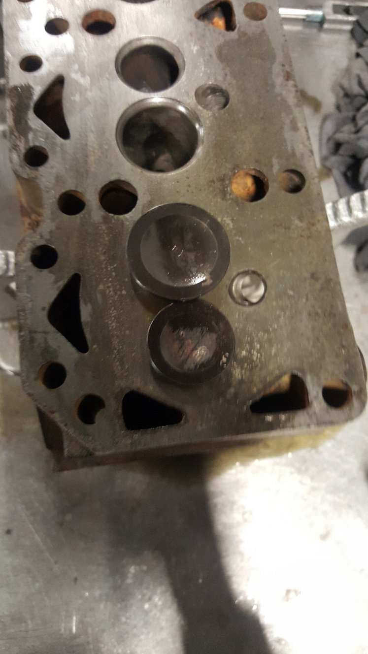
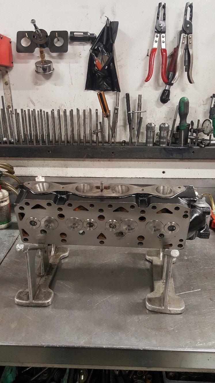
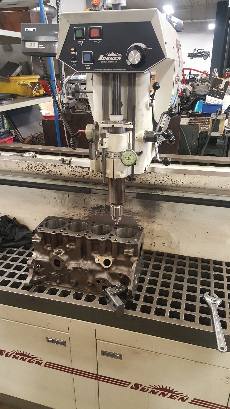
Time to cut some holes for valve seat inserts. We have a Sunnen VGS for all our head work. First picture is setting up the tool cutter to cut the hole. We are looking for between 3-5 tho crush. Once holes are cut just hammer the inserts in. Then turned down a intake valve and a exhaust so had something to check valve spacing and clearance of the side of the bore. I detopped the inserts in the VGS and then surfaced the head. I didn't get a picture of it in the surface grinder as there's pictures of that previously. Here's the valves. And a shot of the head bolted on to the block looking into the bore to see how much clearance the valves have off the side of the bore.
- 27 replies
-
- 18
-
-
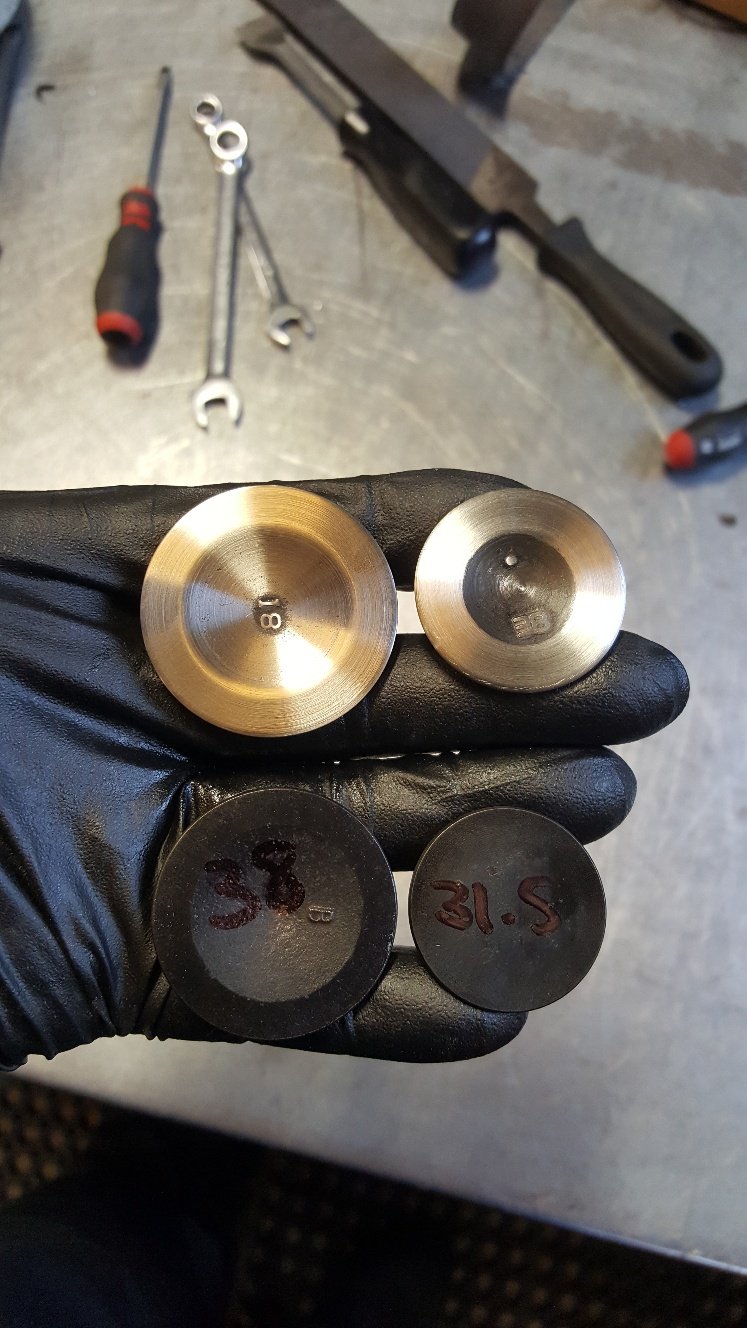
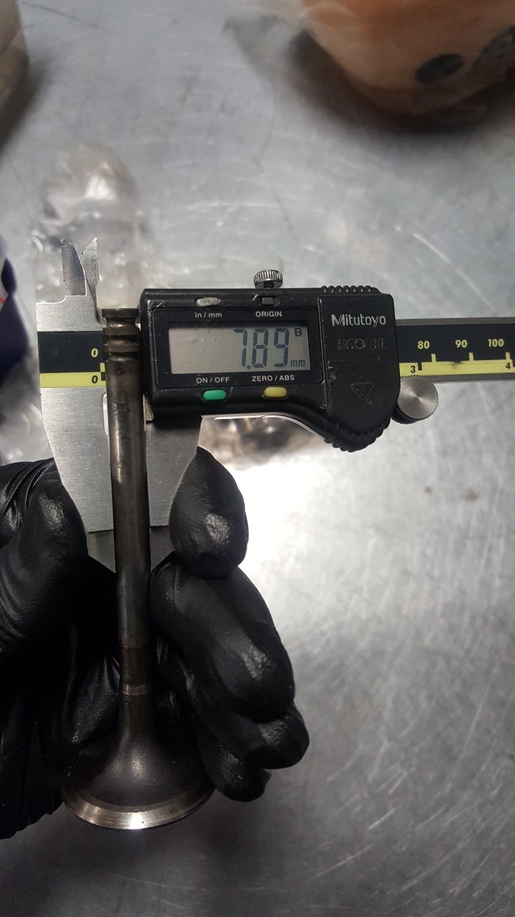
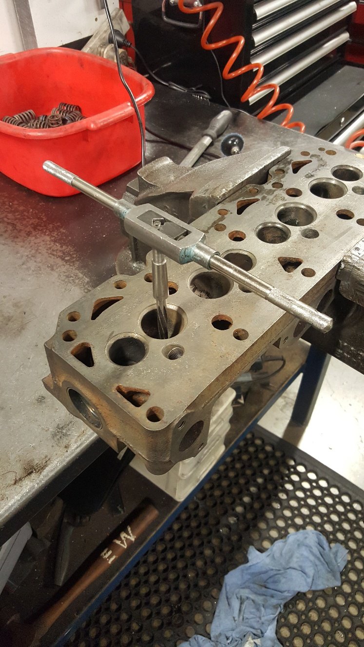
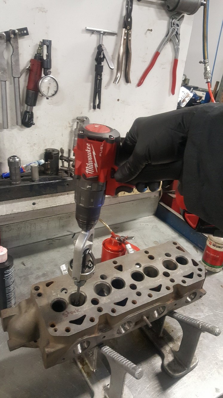
Here's a picture of the standard valve stem size Here's the Mazda FE valve stem size. So I need to open the guides up to accept the bigger stem size. This is also good because it means I don't need to fit a new valve guide. Its just a matter of reaming the guide hole the honing to finished size And now the guides are big enough to get the valves in. I will be machining these down to 42mm for the intake and 34.5mm for the exhaust.
- 27 replies
-
- 16
-
-
So I turned a Accumulator groove into my pistons. Its a groove machined into the ring land between the top and second ring. This groove accumulates residual gasses from combustion to stop ring flutter improving ring seal. I also added some Contact Reduction Grooves in the top land these limit piston to cylinder contact during high rpm and high temperature. They also disrupt detonation waves. Now I've pretty much got most of the bottom end machined except for the valve reliefs. But to machine these I need to figure out what size I want to make my valves. Here's a picture of standard valves vs some oversize valves. I won't be useing these particular valves. I will make some valves out of Mazda/Ford FE 8v valves. While the head was lying around my work mate Al decided he would do a little porting to open up the intake runner where it pinches down at the intake manifold face. You can see he has opened it up enough to be able to run the calipers down the runner to the bowl area without it pinching the calipers this tells him he's got it pretty evenly round. This should give good even area volume. So the intake flow stays at a even speed. Before hand you would expect the intake flow was speeding up through this area then slowing down before getting to the back of the valve. Hopefully I explained this ok. I'm no guru on porting. This is just rough cut off the burr. We will probably leave it that way as it can help in atomization.
- 27 replies
-
- 14
-
-
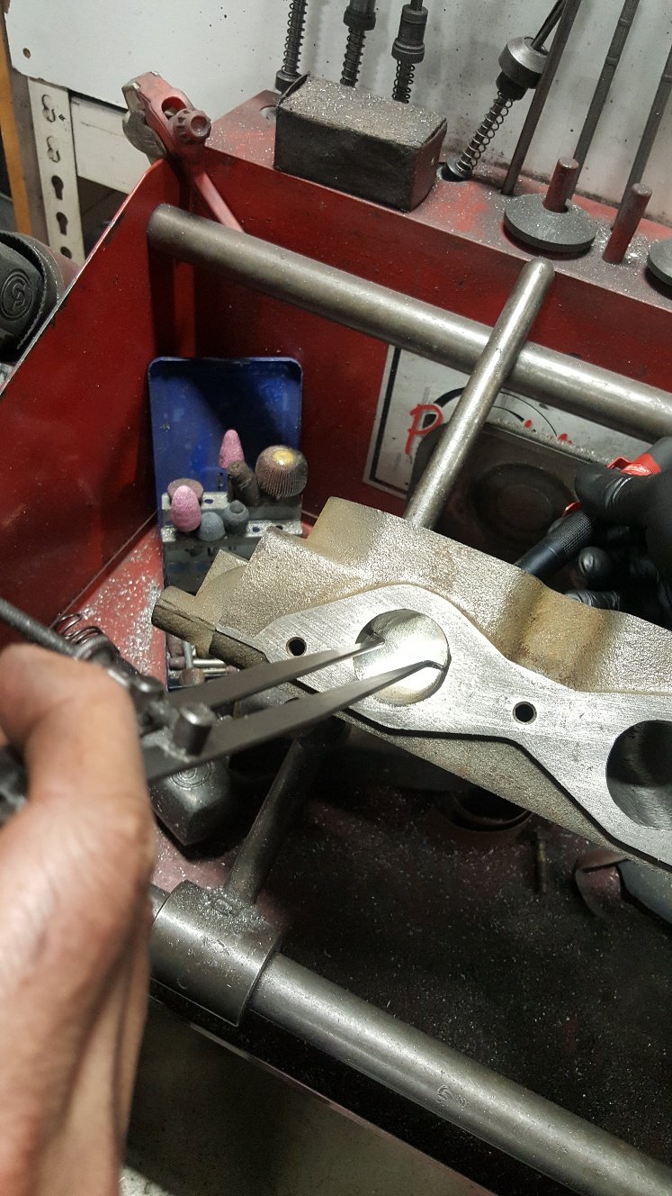
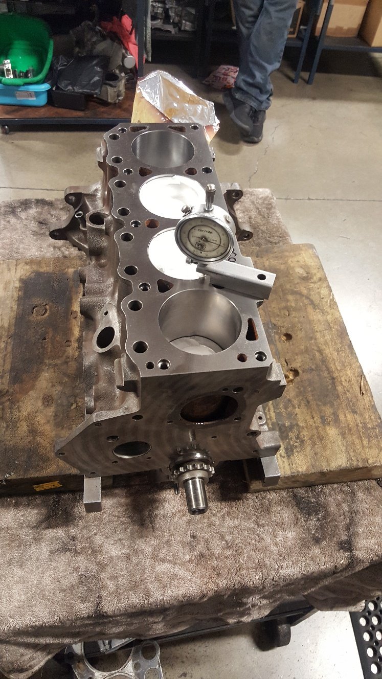
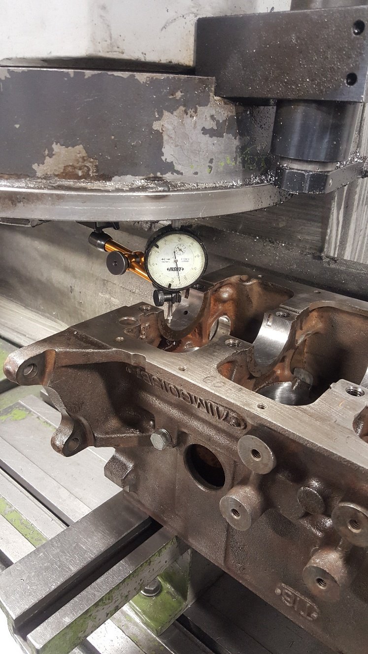
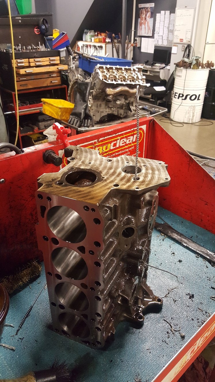
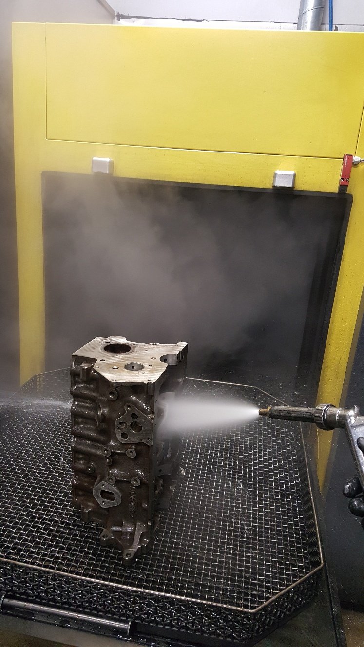
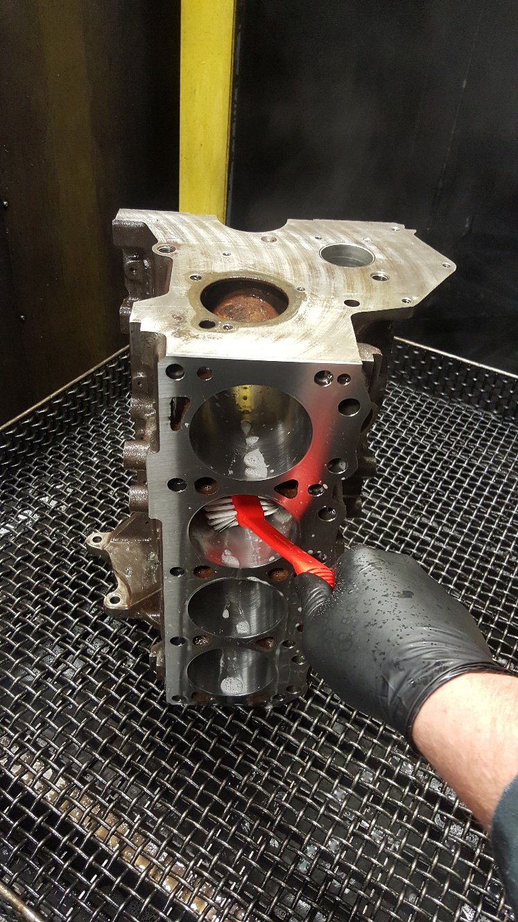
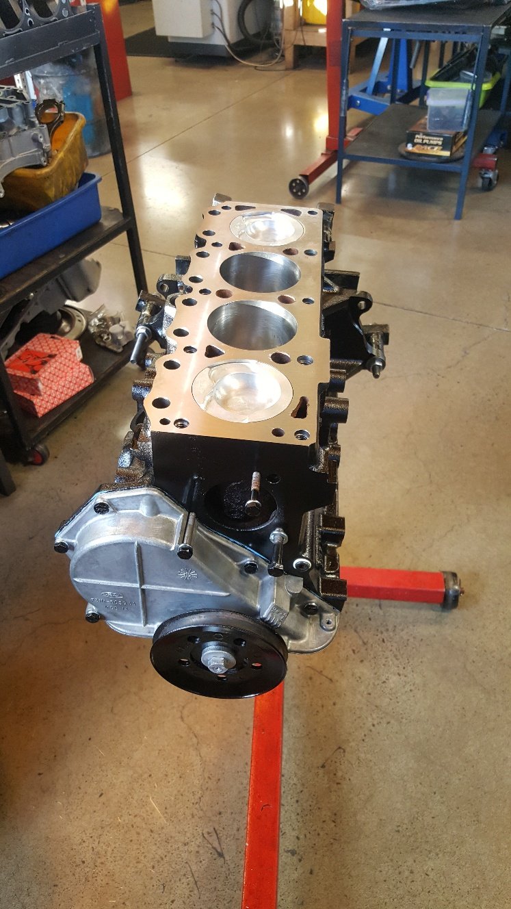
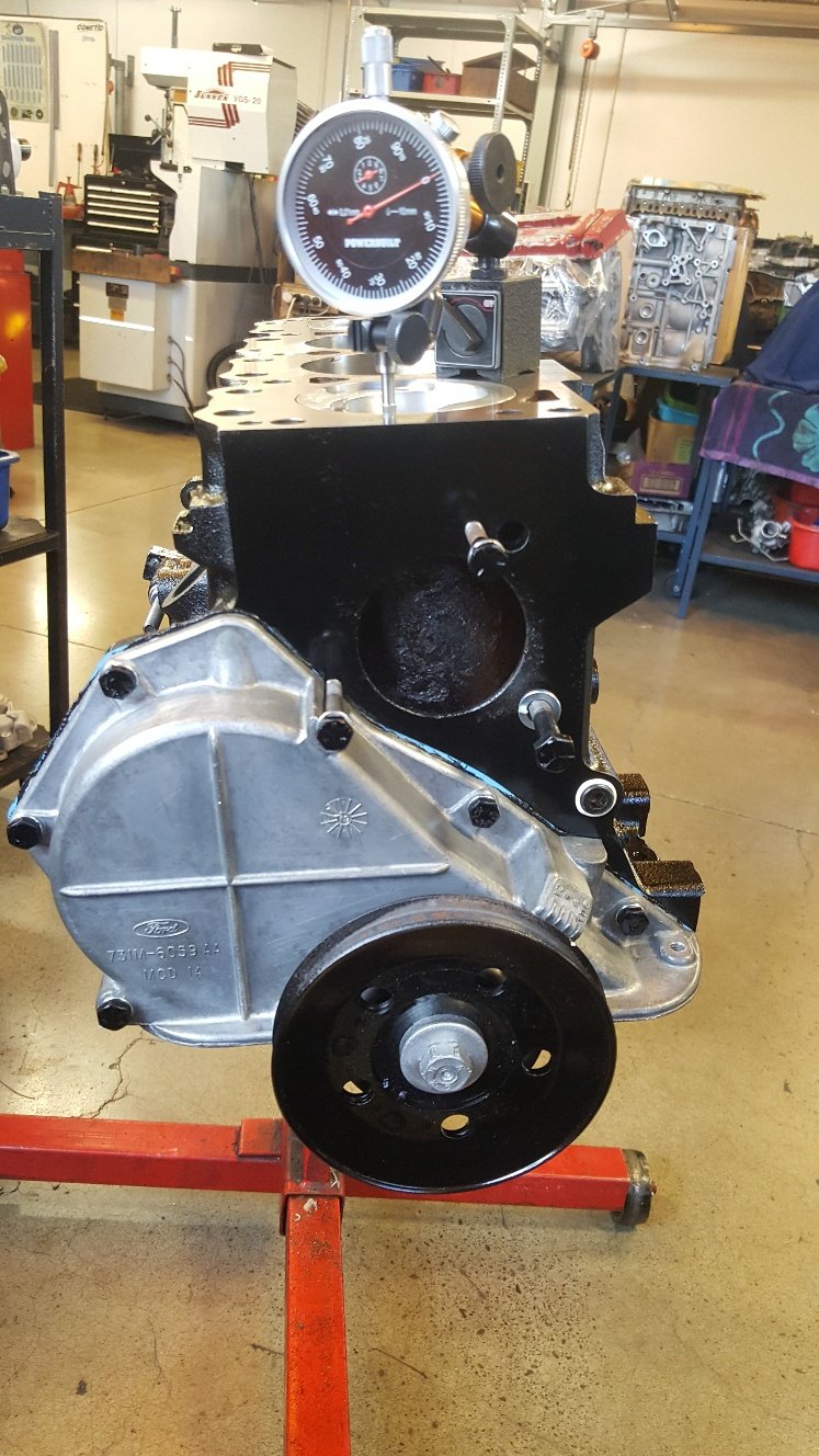
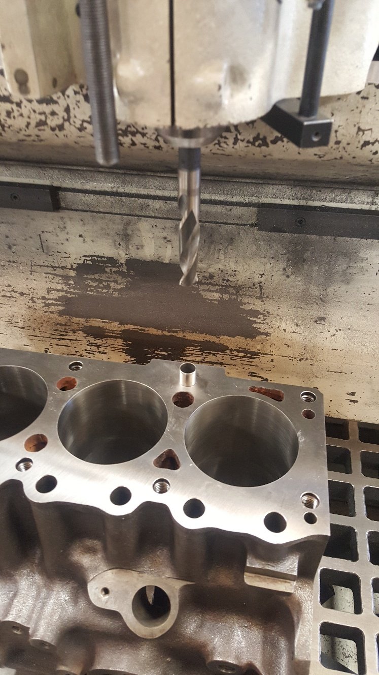
So assembled the short block to check piston heights. Normally old engines have heaps of piston to head clearance. I found the pistons are below the deck surface 20 thou or half a mm. My head gasket 52 thou thick. So ideally i won't the piston above the deck 10 thou to get my 40 thou piston to head clearance for good squish. So it was back to the surface grinder to remove 30 thou. While i was there i sat the block in the surface grinder on it's deck surface and run a dti through the main tunnel to check how true the tunnel is to the deck and i was surprised to find it was within 1.5 thou. I haven't put a pic of it being surfaced as there's already one earlier on. So I gave it a wash. I went through all the galleries with gallery brushes. Then put it in our Bupi wash. This is pretty much just a big dish washer. Made in Germany and it's one of the more handy things in the workshop. Then we just give them a good going over with soapy water. Normally just dish washing liquid and hot water to brake down any left over honing oil. And really get all the machining swarf out of the oil galleries and other spots in the block.
- 27 replies
-
- 20
-

.jpg.2a6003d32e21336304670897ea4543b1.jpg)
.jpg.5d75569ebbf663236399a7c709d29294.jpg)
.jpg.db70df7d6c36e9aa5063bb21c32c6056.jpg)
.jpg.7af975b66560103922d164cb7e4f3dfb.jpg)
.jpg.7d2ef8f377cb12fc982239e9f33dc19e.jpg)
.jpg.02fb83e4ea2824f4c4e3193354270603.jpg)
.jpg.6f011ed18631e3fad3d8cca231257e09.jpg)
.jpg.d964ddaa38e99787cba52c1d867206dd.jpg)
.jpg.5513c7c1219f5ac42937f6184b3baf6e.jpg)
.jpg.43ca509a96e73b9bb06a135e3da07e0d.jpg)


.jpg.2739ceea4562b1a4c9bc4bec0498464c.jpg)
.jpg.8457b1bcdd62d060a0169e5117ec3a54.jpg)
.jpg.78418e84f1243825758bab88a226bc27.jpg)
.jpg.f3bd77e0f27702cd07f897e06d2f1487.jpg)
.jpg.6e7fb716077b37ca5360f0280318290c.jpg)

.jpg.6bad9a6445b94f09aa1f2c7b8234b610.jpg)
.jpg.545f8d51bfdc7a5686662b67bbd75739.jpg)
.jpg.3227af7b75300c0b66faf772e209db31.jpg)
.jpg.5f805a6cfb842fa8306033f88f8916e3.jpg)
.jpg.85d77c8af690c47279b517535edb8caf.jpg)
.jpg.581c90704662574e0a970a55f37722c7.jpg)
.jpg.5fa267efc35a6bf42cb348ed931d77c3.jpg)
.jpg.af1c754ef7f486cec470f40f3756f389.jpg)
.jpg.419fa298e2d0e54da445eec3b78f9c95.jpg)
.jpg.f29fb048178ff1065a621e7eea5277fd.jpg)
.jpg.fad084fe446608465f7c0af112e953ce.jpg)
.jpg.751d99e600c4bd5ff389dbe2554b0cb5.jpg)