Roman
-
Posts
6756 -
Joined
-
Last visited
-
Days Won
32
Everything posted by Roman
-
I'd have thought that whatever the load source, you'd just have slightly different VE numbers at low throttle with it disconnected?
-
But higher differential fuel pressure is better fuel economy
-
I'd go a step further and not bother putting vac on the FPR at all. As there's no real point in reducing fuel pressure for NA setup.
-
If you advance the ignition timing and the engine wants to make more power, but it cant because it knocks - then higher octane fuel will help your motor make more power, by allowing more ignition timing without knock. If you advance the ignition timing and the engine makes same or less power, with no knock. Then a higher octane fuel wont do anything. If you just switched fuel to something different with no other changes, it's unlikely you'll make any more power. Unless you're using partially oxygenated fuels (like E85) or nitromethane or whatever. hah. I'm fairly sure that back in the day, when MSNZ banned avgas for racing (or something similar, paraphrasing horribly probably) Everyone had a big sook about it, but then retuned their cars for 98 octane and found they made the same or more power anyway.
-
Generally a waste of time compared to 98 octane pump gas. The only reason I can see to use it would be if there's some specific reason you need leaded fuel. Like some janky old valve seats or whatever.
-
680kg?! What the hell is in it?
-
I remember a mate told me ages ago: Take any car to a track, and it will do XYZ laptime. -If you have a rollcage, you'll go a second quicker. -If you have a trailer, you'll go a second quicker. -If you dont give a shit about hurting the car, you'll go a second quicker. -If you dont give a shit about hurting yourself, you'll go a second quicker. Not exactly a 1:1 relationship to drag times but the general ethos seems to hold true. haha. Will be cool to see how well it hooks up on the good tyres! Be some good gains there
-
Yeah im starting to see a clearer picture about how people notice the handling difference with engine weight. In a small car at least. Although its funny that some car reviews etc love to mentally associate capacity with weight. "Oh this car is a nose heavy pig with the big engine" When the more modern bigger capacity engine weighs less than an old small one they loved. Ha.
-
Hybrid battery? I dont have any of those
-
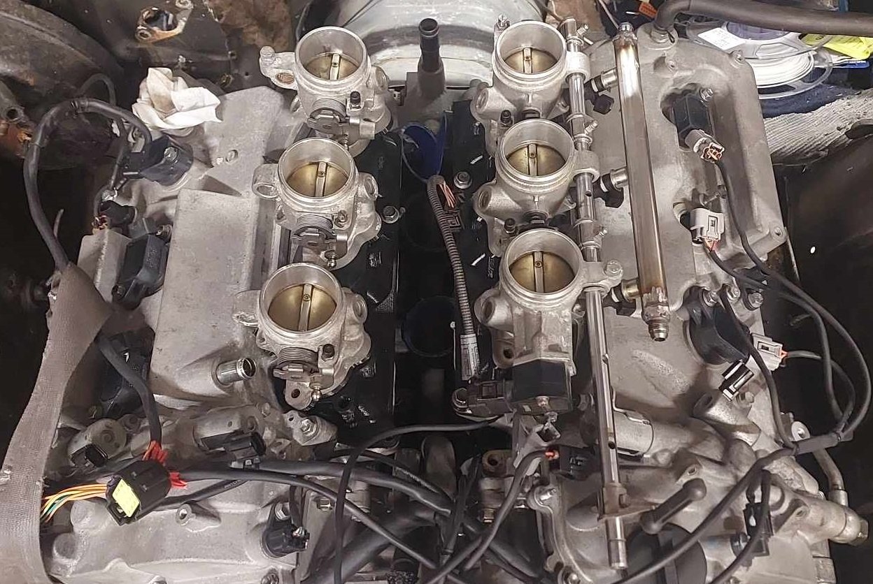
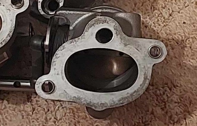
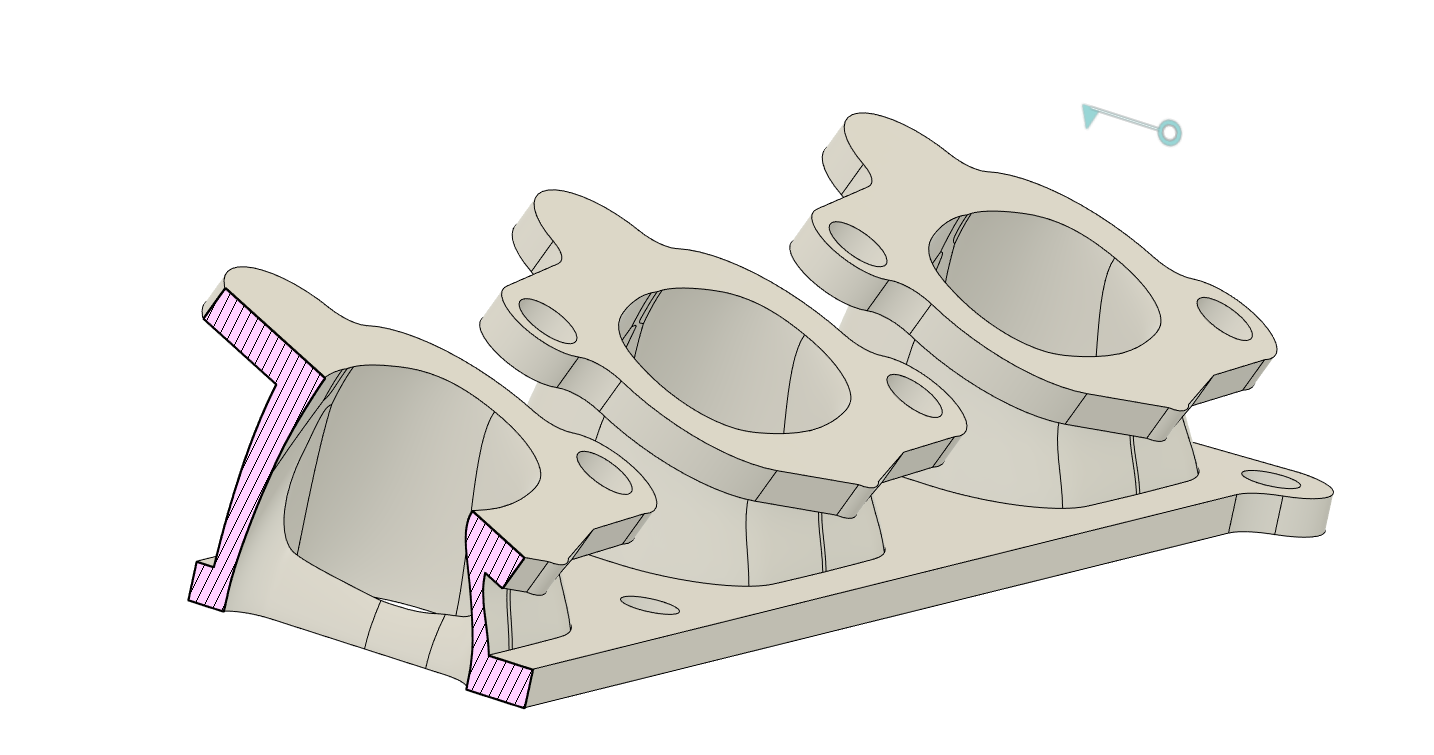
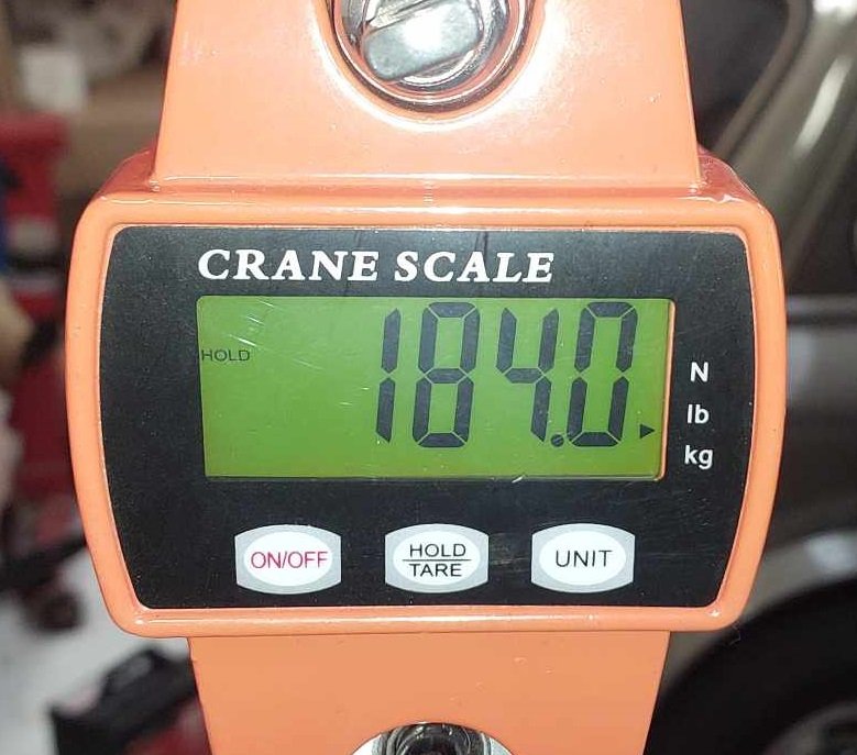
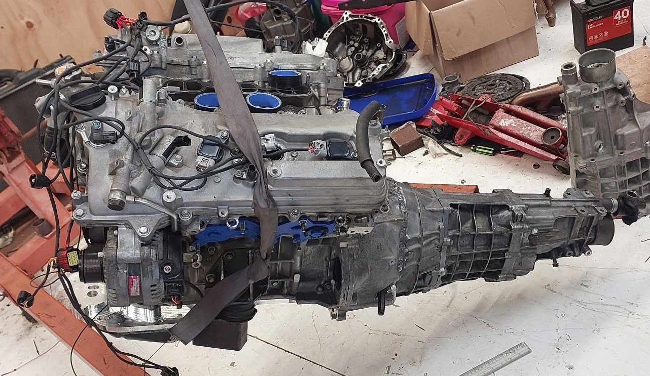
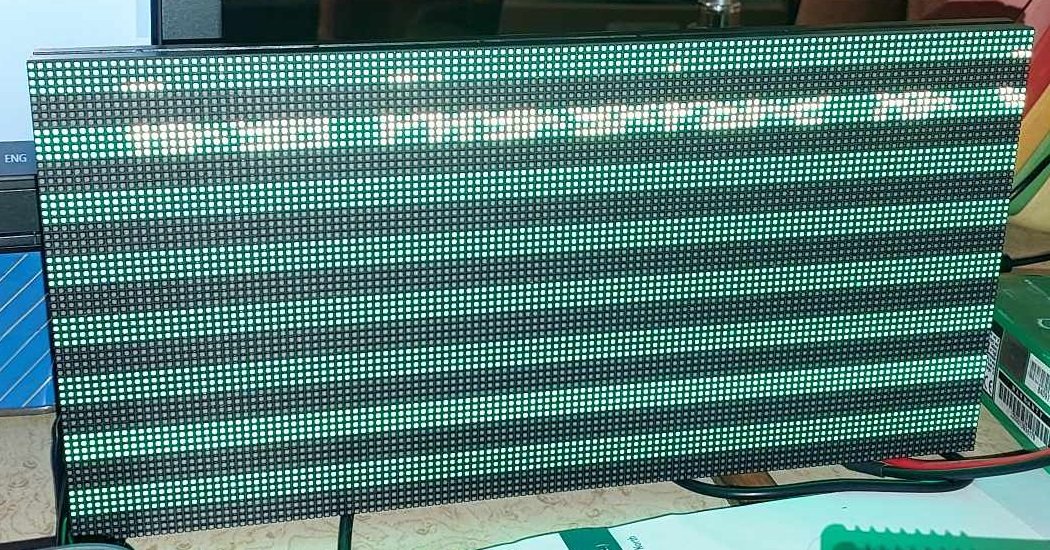
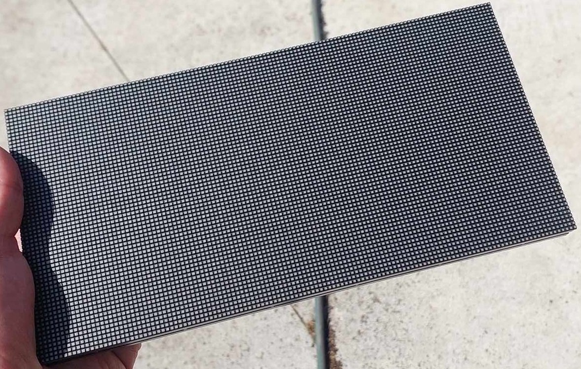
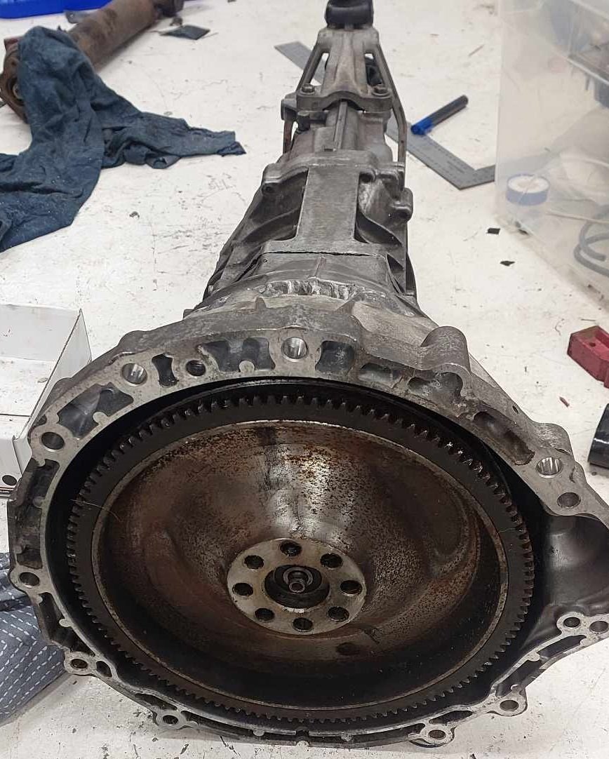
Sump Stuff I managed to get the sump finished off, in place and gooed up. Since I am not exactly sure about how much oil it can hold, and it's probably a good idea to iteratively mark the dipstick as I add 1 litre at a time. I just poured 5 litres straight in, because, fuck it. This worked out reasonably well, the high tide mark is just below top cover of the pan. The oil pump and filter will hold a bit more oil when it's turned over, and the external oil tubes that run up to the cam covers for VVTI and oil spraying the cams. Actually have non return valves in them, so hold a bit of oil up there too. Then, some amount of oil stays in constant circulation while the motor runs, more so at high rpm. So hopefully that's around a good amount. It's not weed its oil all over the floor, it's still good. Exciting! Digidash Fuckery So my replacement LED screen turned up, aannnndddd... I just cant get it to work properly. It only displays the top 4 lines, then skips 4 lines, then next 4 lines, etc. The way these work is actually really complex. I think this particular screen is incompatible with the only available library for controlling these screens, which is a real pity. This doesnt photograph well, but this looks absolutely AMAZING in person. It would be absolutely incredibly awesome as a dash. So I think I might need to buy some of the smaller screens that are supported, and daisy chain them together. As they have different chips controlling the LEDs, or some crap like that. Dunno. But it's way over my head to try and troubleshoot what's going wrong here. However, In the meantime I can still figure out how it works, and draw some graphics on it. So long as I dont mind everything can only be 4 pixels high, haha. Flywheel Stuff Dad got the ring gear machined to the right dimensions for shrinking onto the flywheel. However when skimming down the back of the flywheel, the tool ugga dugga-d itself into the part. or something. Nothing catastrophic for the part or the machine, but bloody scary apparently! Luckily he's smarter than me, and this happened only a few mm from the top, we wasnt trying to cut the whole 10mm out at once. He said once he found better tool speed and feed rate that suits the chromoly, it cut amazingly nicely. So hopefully this isnt far off, anyway. I'm excited that his mill is running. It's damn cool. Intake Stuff I swapped intake setups with @Hurmeez so now I've got the V10 throttles. This solves some problems, but adds some new ones. Firstly, it solves all of my height and fuel rail issues which is a big win. I'll now have some space up top for a nicer shape trumpet, and a sweet looking airbox. Which will also help give some rigidity to each bank of throttles by tying them together at the top. Unfortunately the factory throttle spacing is a little closer together than expected - But, these are a lot easier to space apart. I was considering just leaving it at current spacing, so I can use the fuel rails etc - But nah. It would just nag at me that I'd half assed it. So to space them out I just need to redrill some holes on the rails, to rebolt the linkages in a new position. Otherwise, if it's close enough I might be able to slot or extend the linkages to just push them across a bit. Then I'll need some new fuel rail extrusion, and drill them. But this is all easy drilling stuff that can be done no prob on a manual mill. The center to center on these throttles is 98mm, not the 107mm I was expecting. (Could old forum information be wrong?! shock horror etc) Also they have a highly oval outlet, and the throttles have a 24 degree curve. Despite have a big entry size and quite big throttle, somewhere around 50mm. They taper down to the cross sectional area of a 42mm circle at the exit. However there's enough meat around the perimeter that they could easily be ported out to the area equivilent of at least a 48mm circle no problem at all. In order to get the top of the throttles standing vertically, I need a manifold that cancels out the 24 degree angle. Here's where I am currently at for prototype shape: Since can align each throttle central over each port, all of the port shapes are now identical which is nice. The engine they are from (S65 V10) makes 500hp from 5 litres, so around 50hp per throttle. So that's equivalent to 300hp using 6 throttles. So hopefully injector size, airflow etc all plenty suitable for the application. I'll also have 4x throttles left over, so it might be interesting to see how these look against the port shape of 1NZ or something. Engine Weight @flyingbrick loaned me his scales (thanks) so I could get a ballpark weight for motor. I've not gone quite to the level of @Hyperblade's awesome post about engine weights at this stage - as I still dont have some parts to put on. However, with the motor and box put together. Engine mounts on. No starter/flywheel/manifolds. Like so: Total weight came to: 184 kg. A J160 is 38kg, putting the 4GR around 146kg. A little lighter than expected, given the service weight was listed as 165kg for engine. So this puts it at slightly heavier than a beams motor once it's fully dressed. Much heavier than a K20, and the weight of almost 2 1NZs. Ha! So I'm not gonna win any awards for worlds lightest engine, unfortunately. (Did I ever mention how great a 1NZ is? Cant remember) However I'm also relieved that it's not going to be massively different to the beams setup. The fact that the weight is further back and lower down will hopefully help offset the extra podge. For some less discouraging context - comparing to a previous generation Toyota NA 2500cc six cyl engine, the 1JZGE. This was 207kg for the engine alone. So my motor and gearbox weighs 25kg less than just an NA 1JZ. ha! Before @xsspeed mentions RB in my thread again, an RB20DET is supposedly around 245kg which I assume is with turbos etc mounted. So lots of different things going on, the most exciting thing on the to-do will be getting the flywheel in place. As once that's done, I can crank the motor over and get some oil circulating through everything. I need to assess if my tiny lithium battery is going to have enough grunt to turn the motor over, before I waste a bunch of time building my wiring etc around a battery that might not be suitable. Hopefully it's good though, as it cranked the 1NZ way faster than the regular battery did.

- 75 replies
-
- 32
-

-

-
Yeah another thing is that the accusump then needs to fill itself back up after its pushed all the oil back into the pump. So I guess its more like it takes an oil pressure loss peak and dampens it down / spreads it out to less pressure drop over a longer time period. But on long sweepers it aint gonna do shit, unless its only the initial tip-in on corner entry that is causing starvation.
-
It was so cool to watch and be involved in it, even if I was only in charge of manning the broom and patting the dog. Definitely learned a lot, as well as it just being exciting to watch the final part taking shape from the big piece initially. On the weekend I got the welds flattened off, tapped all of the holes, and did an absolutely horrendous job of welding the oil pickup. But it's nearly all ready to put it all in place and goo it up for good. I've only noticed one small thing I wish I did differently. The area that the dipstick hole pokes through is only very thin. (3mm I think) I should have left that thicker so it could support the bottom of the tube. I guess I should have spent some time sorting out the dipstick at the 3d printing phase. However that's easy enough to work around. On the whole I'm super happy that it's all worked out so well.
-
Yeah there's a few options to do this. But not planning on it. I hate having external lines running everywhere. It's got it's absolutey colossal whale sized block to help dissipate oil heat. And yes a dry sump would be great, someone gimme 5 grand of whatever it costs and I'll do it. haha.
-
I think it'll be around 5 litres to fill it. Yes since it's a non standard setup it's definitely a possibility that it might have some issues. Main concern is that there's way less room under the windage tray/crank compared to factory setup. So I'm not sure how well the oil will flow back to the sump. But again, just one of those situations where just need to fit an oil pressure sensor and monitor it. Have some good alarms on it.
-
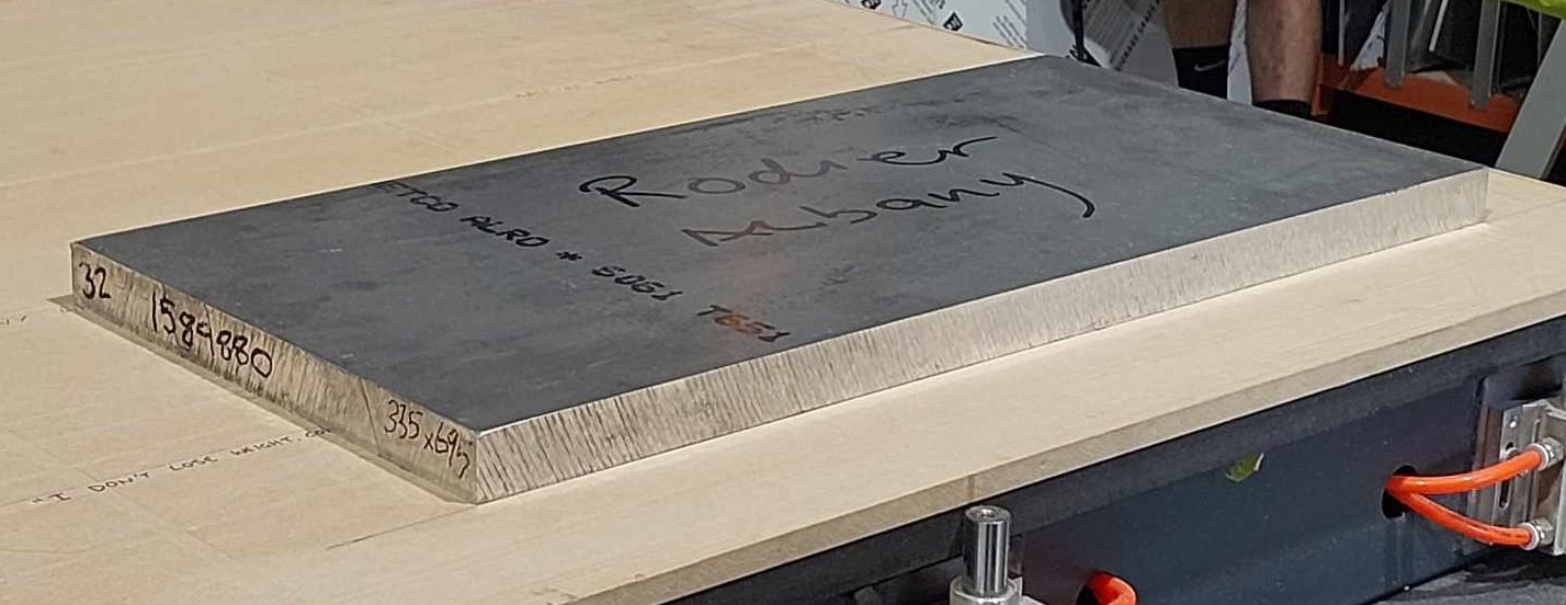
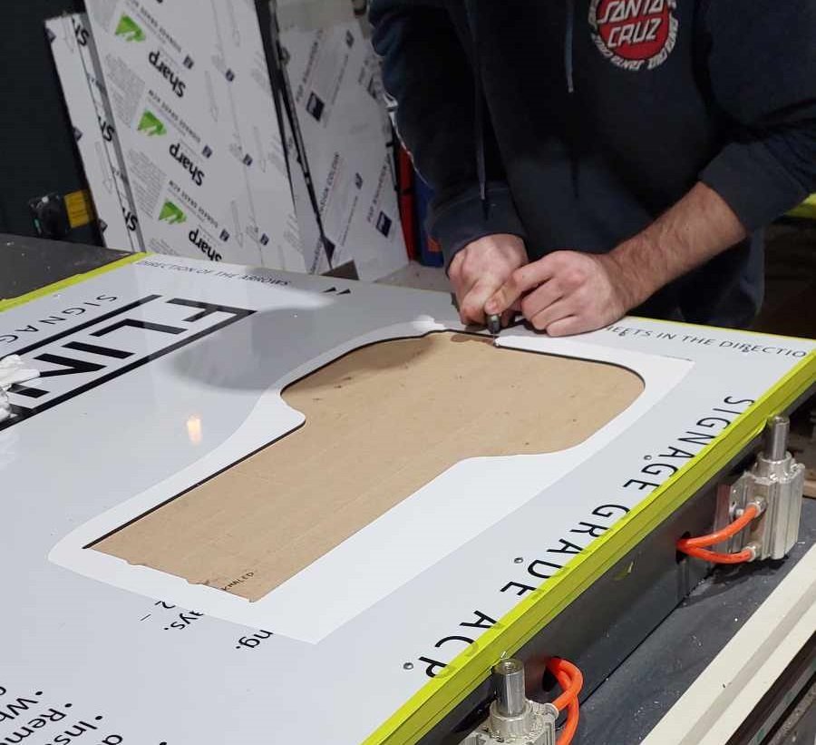
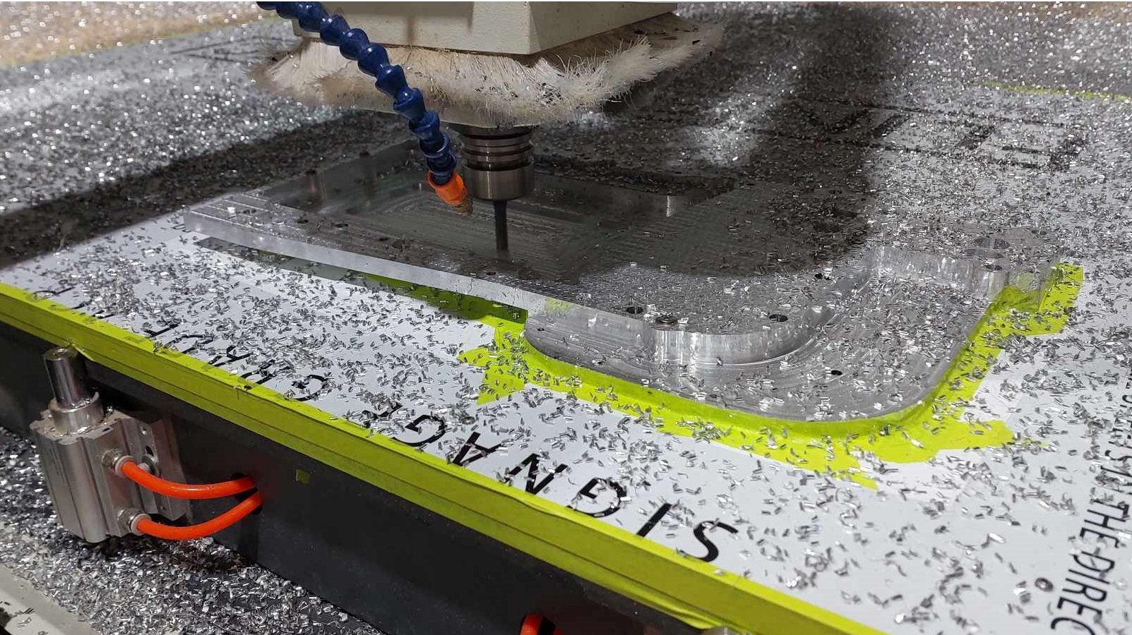
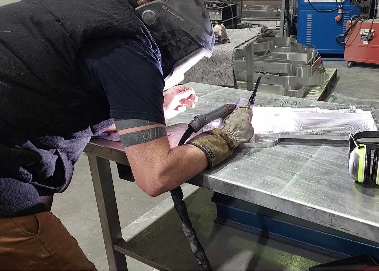
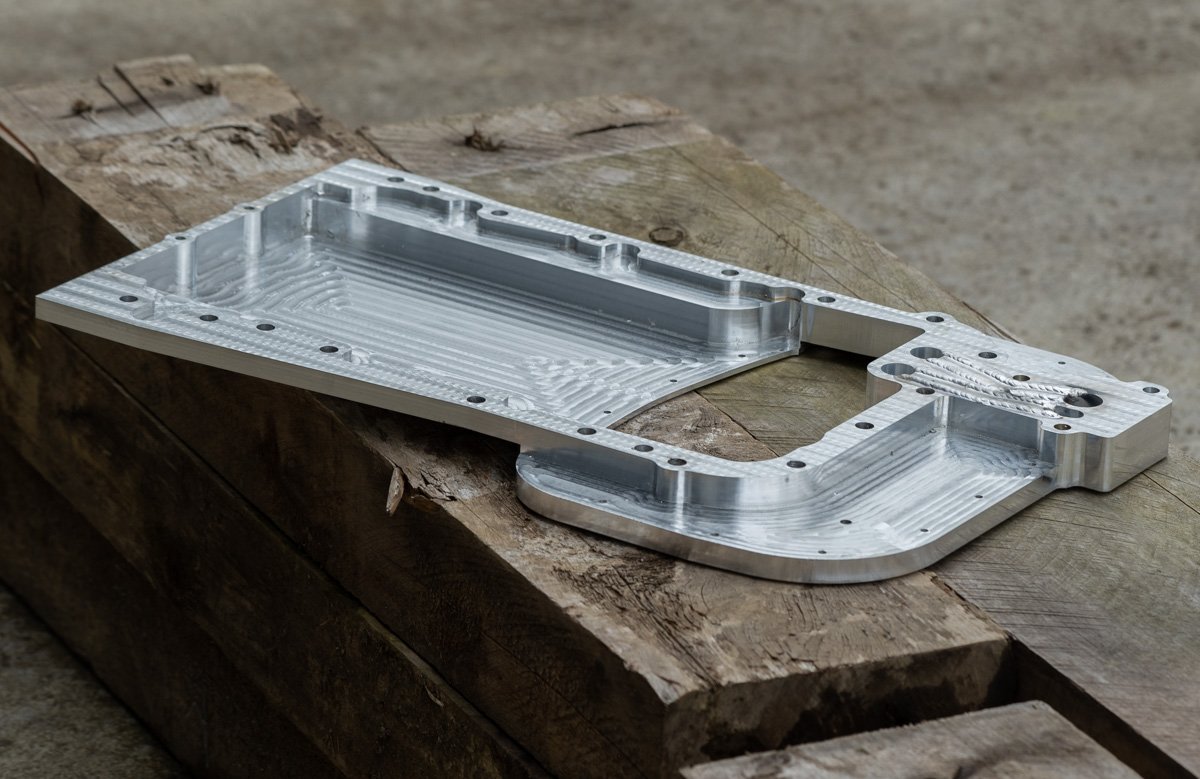
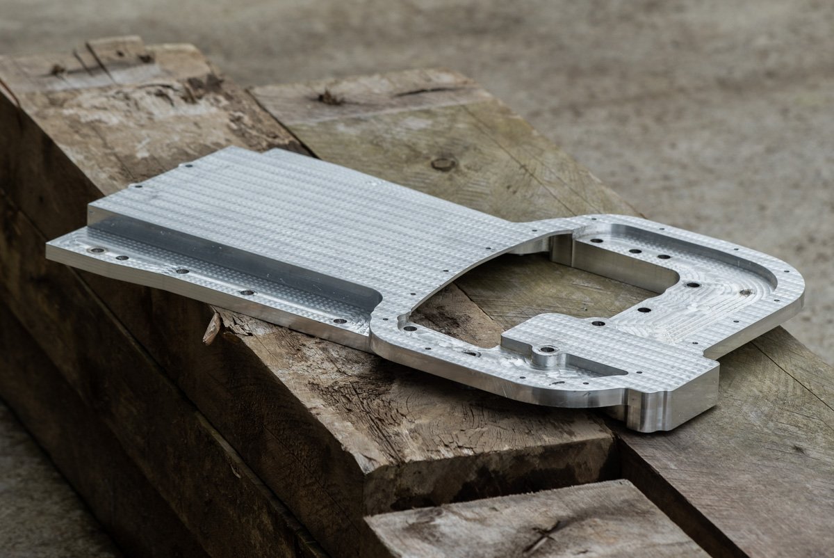
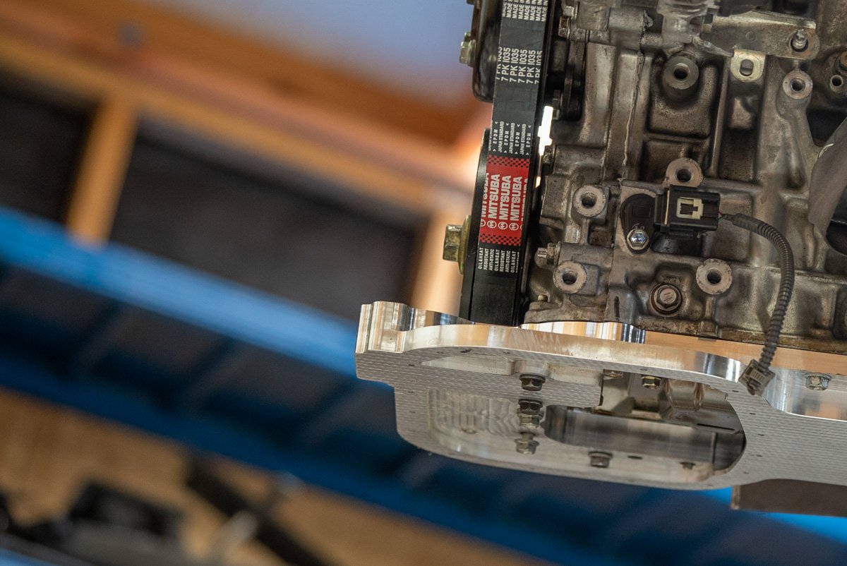
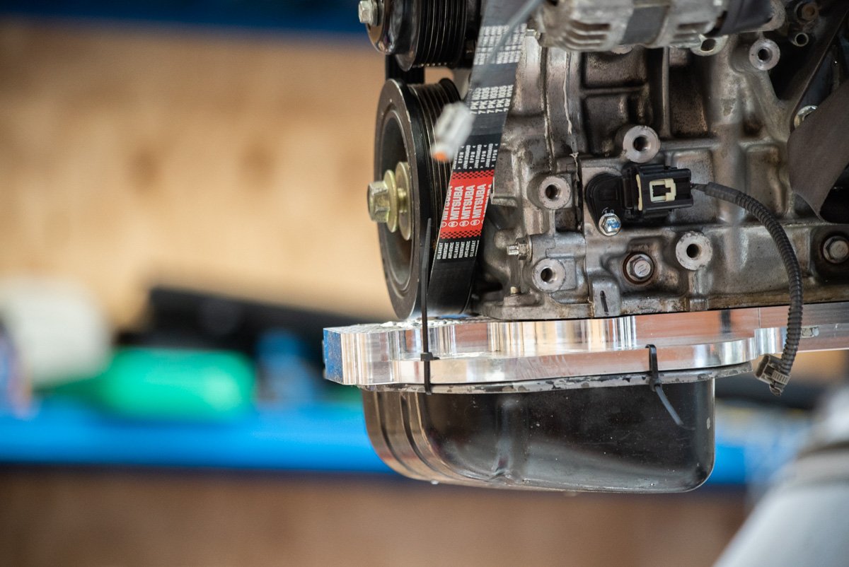
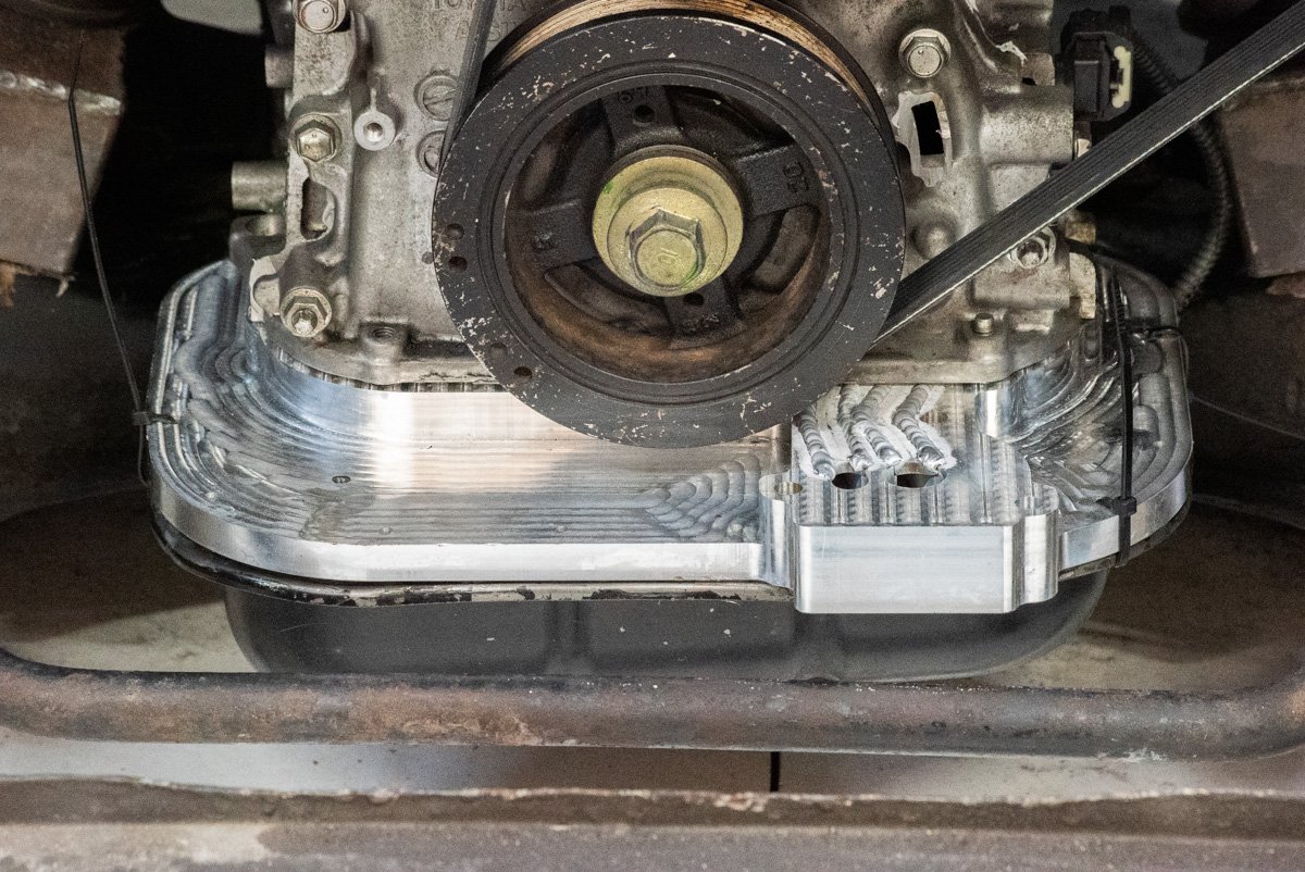
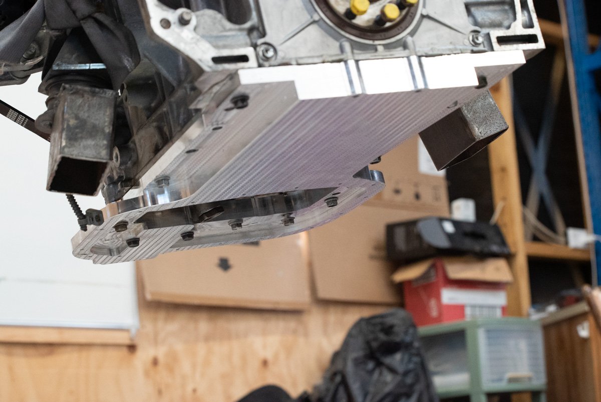
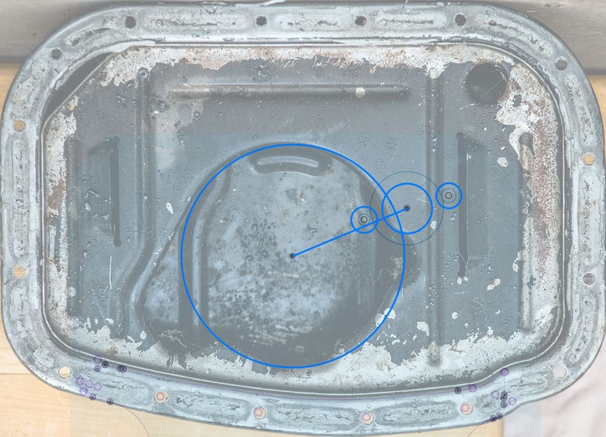
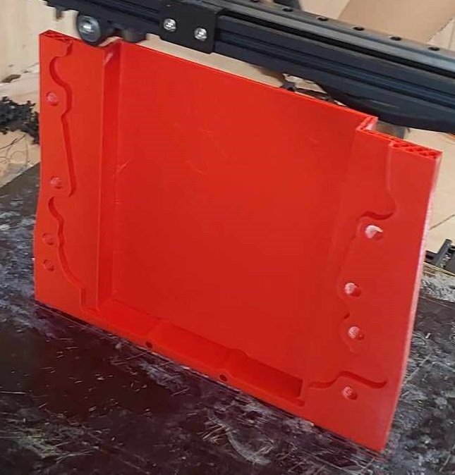
Oil pan activities! Absolute GCs @Stu and his workmate Sam found some time in their incredibly busy schedule. To spend a night programming some cutting paths and cutting a big slab of alloy down into an oil pan. I went along to watch and learn some things and it was awesome. Firstly, start out with a 22kg block of 32mm thick alloy plate. Then align this onto the bed of the router, and the it gets sorta vacuum sealed against the bed. Then one side was machined, making an absolutely hectic amount of mess. Then it was flipped over, and a a template was cut to align it onto the bed again. Making zillions of glitter carving out the other side. Then once it was all cut, we are down to around 1.8kg from 22. So there were plenty of chips for me to sweep up, haha. we needed to look at drilling the oil galleries for the filter, that I mentioned a few posts ago. Problem - the depth needed was too long for any available tooling and the height of the machines etc. So we decided to mill two slots in, and then weld a cover plate over the top. We made the slots do a bit of a zig zag, so that they would avoid one of the threaded holes for the oil filter housing. Which previously penetrated through into the oil gallery as there was no other way. Then Stu on the tig to zip it all back up: Then ready for a test fit. How good! (It still needs the welds flattened off and some threads tapped, havent done this yet) Much to my relief, it fits up great. Just zip tieing the oil pan on for now, until I can tap the holes. and back in the car... everything good! So that's one of the last remaining big tasks mostly sorted. And a big relief that it looks like everything is going to work as expected. Hugely grateful for the time spent by Stu and Sam to help get this done. I think its the most complex and coolest car related thing I've ever drawn up. Next steps are to thread a few holes for the oil pan and oil filter, flatten off the welds, and make an oil pickup. then I can fit it on for good, and fill the motor up with oil. Getting closer! Exciting.
- 75 replies
-
- 60
-
-
-
Shanes car was absolutely hectic with the turbo 5E setup. Was 500something horsepower I think? But a massive on/off switch. Since he's put the 2JZ in, I'm pretty sure the 5E setup is all just sitting in his shed... waiting for a good home... Would be awesome in a GT86
-
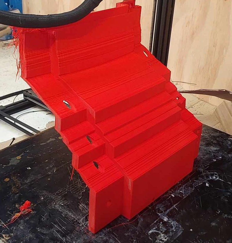
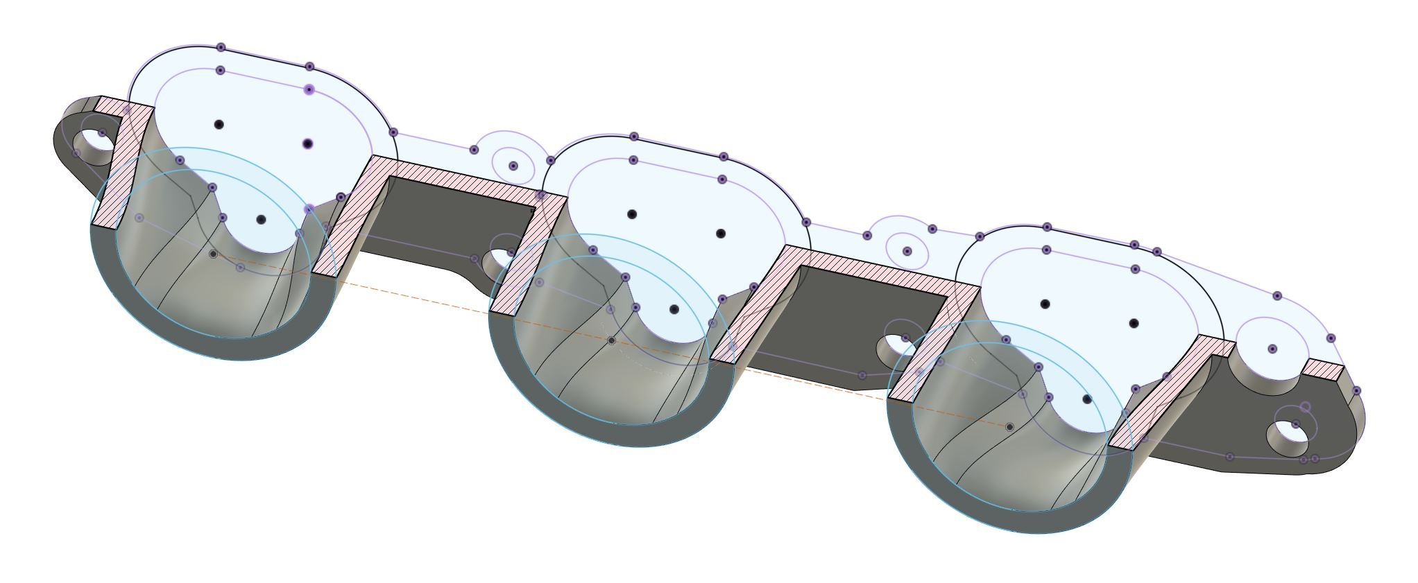
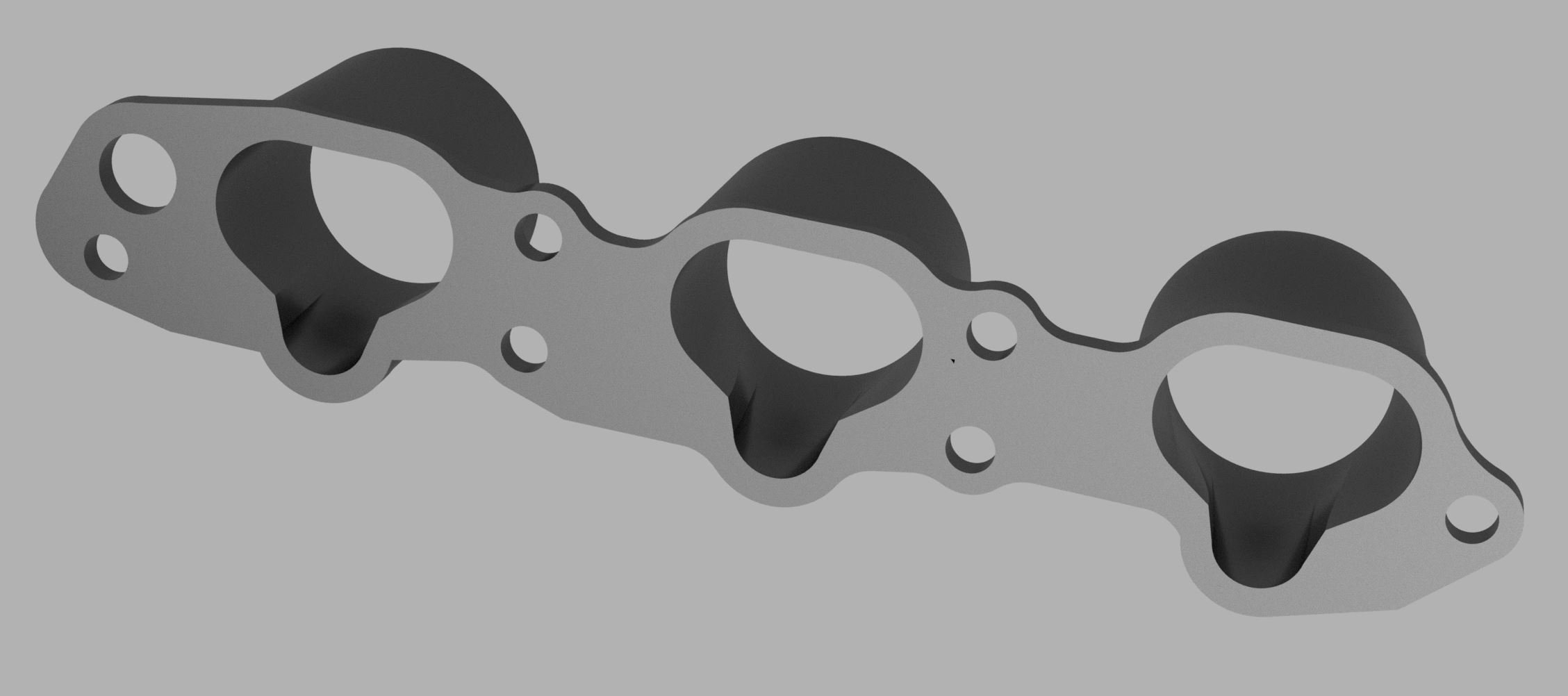
A few bits of progress. Dual e-throttle This has been harder than expected because PID settings that work great on the ECU, are totally different to the PID settings that work on my controller. If anyone wants an easy to digest explanation of PID control, then this video is absolute magic. I end up rewatching it every time I forget what each of the variables do. I've found out the reason for the settings being way different, is that the I and D in P.I.D. are time dependent variables. So if you are refreshing the controller at 100hz, needs totally different values to 200hz (or whatever else) Since the H bridge hardware is different to what's in the ECU as well, It might react at a different speed. So needs different numbers too. I managed to get it tracking fairly close to the ECU controlled throttle, but still had some issues with things like slamming the throttle really hard into the end stop, when it's trying to shut it quickly. I think I need some more complex code to stop integrator windup and maybe some different PID values for when it's opening, vs closing. As the return spring obviously makes it react differently one way to the other. These throttles act quite "sticky" compared to others I've used, like it needs heaps of current to start getting it moving. Then once it's moving, you need to rapidly reduce it towards the target. So its been harder to get the numbers right, even with the ECU controlled bank. I think I'll just resign to the fact that having both throttles run from matching external hardware will be the way to go here. Sidetrack / scope creeping the intake setup I've also still got the nagging issues of that these throttles are closer together than I'd prefer. But I also need to try mount them close to the ports so I've got bonnet clearance - which means my manifold shape is okay but a bit yuck. So I've still been half way considering other options while I've been plugging away at other stuff. With some interesting timing I've been chatting with @Hurmeez who has an absolutely kick ass Escort Wagon project, with a Mazda KL V6 engine. Which unfortunately recently was in some flooding but hopefully keeps making good progress soon. He's been using some of the BMW throttles from the V10. However for a few reasons he has ended up needing to run the throttles quite far from the head, in which I think is a really awesome looking setup: However having the throttles mounted in that position presents him with some maintenance difficulties for things like changing spark plugs. He's had similar nagging thoughts in the back of his head, about changing his setup. So he's been looking at options for a more compact throttle setup that can live in the vee. As it turns out, my Triumph throttles are insanely close to the bore spacing of the Mazda V6. The Mazda engine has 97.5mm bore spacing, and the Triumph throttles have a 94mm spacing. Which is pretty damn close to perfect really! I'm not sure if this is the right gasket for his engine, but I found one online and scaled it for a quick sketch of how a manifold might look. Even with quite a short manifold, it looks really good as the throttle distance/size is very similar. So I'll go take my throttles up to Auckland some time so he can have a test fit. Probably easy enough to print a few PLA manifolds for a test fit as well. Then in return, I'll see if I can have a borrow of the BMW throttles too. If it looks like it'll work out well for both of us, we might end up doing a swap. The BMW throttles can more easily be spaced apart, which suits me better. From factory, the BMW throttles use linkages to connect to a single e-throttle motor that runs both banks. So this might get rid of another one of my headaches if I can go down that path instead. So, on one hand I'm not overly keen to scope creep the intake setup when the current setup "works". However eliminating the need for 2 ethrottle motors is appealing. See how it goes! Bellhousing swap So far I've just had empty casings bolted to the back of the bellhousing and motor, so its lighter and easier to test fit everything. However, thought I'd better finally put this on the proper box. Well, this was a friggen headache! The bellhousing should fairly smoothly just slide on over the bearings and front shaft things with a few taps. However what was happening is that it would barely engage on the bearings, then become super tight. I could put in some bolts to wind the front casing on, but then its locked in tight and nothing will rotate - and there's not enough room to get the circlips on the front bearings. I thought maybe the casing had pulled a little, bit from the heat of welding. But it looks like the circlip groove on the bearing had caught on the lip of the housing, and galled the bearing housing, and dragged some shit down into the hole then made stuff worse. So I dremeled a fillet onto the bearing holes, and knocked off the high spots. Then after a lot and I mean a LOT of trial and error I managed to get it all together succesfully. When you pull the front casing off a J160 box, there is a little lever arm that is only held in place by a pin that screws in after the bellhousing is on. So you need to fit a rubberband over it to hold it in place, and hope it is nicely aligned and doesnt pop off when you put the pin through. Which sure enough, it popped off a bunch of times before I managed to make it work. Not a job I hope to repeat any time soon! I also cut a hole for the clutch fork, and shoved a spare clutch/flywheel assembly in there to see if there's enough travel etc. Everything's looking good, hopefully I'll have the modified flywheel back soonish so I can whack it all together and onto the engine, ready to go! Digidash The screen and controller board thing for my LED screen turned up. And it doesnt necessarily show well in pictures but the LED screen looks absolutely super cool! It took a little while longer for the control board to turn up. Once it did, I was looking forward to loading up the demo software and assessing whether this is a viable option for the viewing distance. I remember reading in the instruction manual a few weeks ago, that these can draw a fairly crazy amount of current. They have some grunty big power wires, then regular small wires for the control board etc. So I hooked up a 2amp 12 volt power supply for starters, not sure if this was enough. A few lines on the screen were flashing, but it wasnt responding to inputs. But it was crazy bright, like burn my brain out bright. I figured it was drawing more than 2 amps, so I connected it straight to a 12v battery annnnnddddd blew it to smithereens So back to RTFM and yeah it turns out that it does draw lots of current... But with a 5 volt power supply, not 12 volt. Haha. Oh man. So I've paid the stupid tax and ordered another one, but will be a few weeks away until I can see how well it will work. Finalizing engine height I printed a section of the new sump design, so I can finalize and minimize my engine height. I thought I'd print this at double speed, because I am impatient. This turned out great: So after throwing that in the bin, I had to end up printing another one anyway, at regular speed. Which turned out properly. Ha. There's probably a life lesson in there somewhere. With some plasticine measurements, eyeballing, and iterative cuts lower. I managed to get the engine around another 7mm further down. with what I'm hoping is acceptable clearance to the crossmember. I was considering cutting a dish section into the crossmember, but there's no point - As the steering rack is currently about level with the crossmember's max height anyway. There's no way I'd want to lower the steering rack, or space down the crossmember as both of these options are nasty for steering geometry. I would also have another issue, that the bottom of the bellhousing is getting perilously close to the road. Even at the ride height the car is currently at, which is hardly mega slammed. But, it's about ready to have the crossmember mounts welded on which is cool. Oil pickup tube Since this motor usually has the oil pickup right down the back, but oil pump up the front. It's got a very long oil pickup tube, like so: So I need to modify or replace this, and I've not done anything yet. Thankfully since I have a cad drawing of both the new sump part, and the altezza pan relative to each other. It's easy to work out the new position without lots of fiddling around to take the pan off and on etc. So the new pickup is going to be about 70mm across, but annoyingly it will cross over the bolt hole. So I think it'll need to run it's original direction for a bit first, then have a bend to reach it's target. I might sit it a little further back than center of the hole, because I'm guessing acceleration will be the worst case scenario for oiling when I've only got a very shallow pan under the windage tray. So I've at least got some semblance of a plan before I go cutting everything up. I might print a little jig to show the position it needs to end up in relative to the pickup bolt holes. Might print it at regular speed this time, who knows. Firewall fixup Since I'm reasonably close to having the motor all sorted, it makes sense to get the engine bay ready for it to go back in, so it can (hopefully) stay in. So I need to make some progress on properly cutting out and then patching up the firewall. So I'm looking for a section of panel steel, around 1000x600mm or so. Does anyone have any for sale? As I'd rather not have to end up buying a 6m length (or whatever) from Steel & Tube, when I'll never end up using the rest of it. So, some slow progress and dumb mistakes but I'm still heading in the right direction overall.
- 75 replies
-
- 25
-
-

Discuss here about Yoeddynz's little Imp project...
Roman replied to yoeddynz's topic in Project Discussion
Will a sight level thing end up getting stained, then hard to see through? Is it not going to have a dipstick? Good progress! -
Hey @Stu thanks for starting the 1E chat thread. I can come help when you're ready to 1E either the white starlet, blue starlet, or AE86.
-
1.9 rod ratio, and at 10,000rpm its mean piston speed is same as a 1NZ at 7500. So keen to see how this goes haha.
-
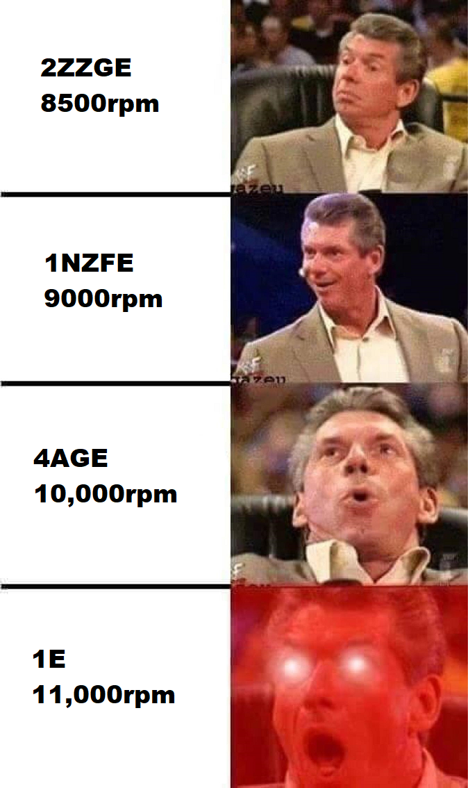
The current state of oldschool.co.nz Toyota meme engines.
- 18 replies
-
- 10
-

-
-
-
Shameless EP starlet fanboy reporting in for duty. Have you considered a 2ZZ 1NZ?
-
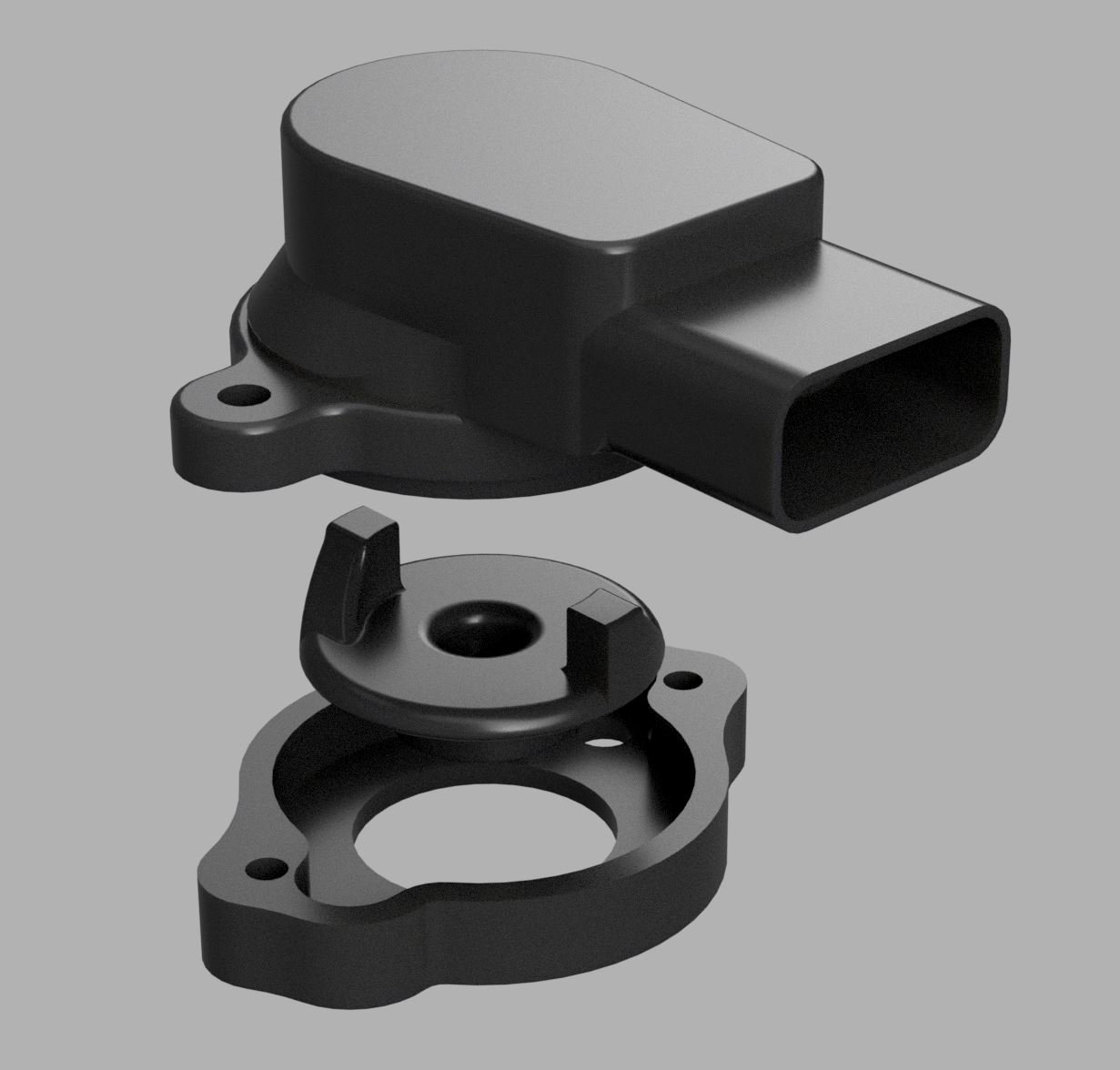
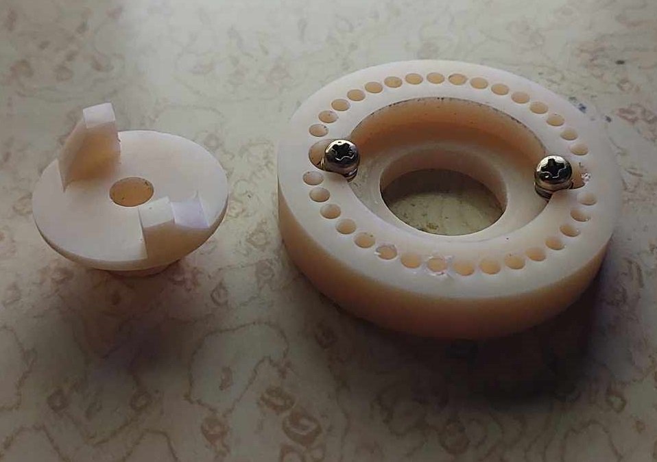
In today's episode of "why the fuck are things this hard" Adapting a TPS to get rid of the stupid magnet based one. Thanks once more to @flyingbrick who has printed me a test version of my TPS adapter on his resin printer. Initally I just needed to figure out where things would end up, to see how to tweak it. So I ended up skinnying it up a lot and adjusting a few bits to make it align and rotate nicely. The (hopefully) final version features a gratuitous amount of fillets, because, thats what you do. Hopefully once this is finished I can finally do some testing on the H bridge setup for the second ethrottle bank.
- 75 replies
-
- 27
-
-
Stu's 4agte 85 EP71 Starlet and 4age 84 AE86 Levin
Roman replied to Stu's topic in Project Discussion
EP starlets are so damn cool. If I could have a dream garage of cars I think a full bodykit factory turbo EP starlet would be in there. The first time I saw a factory turbo one I couldnt believe it. That and the first time I saw a Z20 soarer stick out in my mind was "WTAF!" moments for seeing cool 80s cars in the wild back in the day. haha. -
Rhyscar's Subaru Type RA of teenage dreams... where less is more
Roman replied to Rhyscar's topic in Other Projects
So cool. In my mind, when I think of WRC. The first thing that comes to mind is the era of WRX vs evo battles for supremacy. Maybe with a sprinkle of Puegeot 206 and ST205 GT4. Everyone loves the group B monsters, but the 90s were a golden age for Japanese performance cars gaining some credibility. Generally speaking. It feels like the rally results helped cement this in a decent way. Having the opportunity to own a homologation version of something is so damn cool. It seems crazy that this is even a car that is in any way still affordable to buy.