Roman
-
Posts
6755 -
Joined
-
Last visited
-
Days Won
32
Everything posted by Roman
-
KPR's guide to making your AE85 worth 10x as much: Let it sit for six years This should be in the get rich quick thread
-
Ages ago I bought the Spartan wideband controller that uses the LSU-ADV sensor. This is basically a way faster responding version of the Bosch 4.9 sensors, that is much more resilient to issues from cold starts etc. However unfortunately, the initial version I received, after much troubleshooting wasn't sending or receiving over canbus. I've managed to still use it though, because it has a wire for analog output. So you can use it as a regular 0-5v sensor and wire it to an analog input. But the downsides are that the lambda range is reduced and I think it's a little slower to respond. (its still faster than older sensor though!) So I contacted them and they agreed to send a replacement. It took a while to get back, but the new version looks much better! So I'm going to connect this onto my canbus network, which currently only consists of ECU and my little dash thing. Howeverrrrrrr all going to plan I'll have 4 devices on the bus. As looking at the wheel speed situation, and comparing ABS pumps, and finding their pinouts. I think the tidiest/simplest solution is going to be swapping my ABS pump for one from an NCP91 Vitz (next model up) It's got a lot fewer pins, and it transmits all of the wheel speeds and some extra cool stuff like yaw rate over canbus. However the pump itself, the brackets it sits on, where the brake line ports are. Are all identical so it should be easy to physically swap over. So this means I can get all 4 wheel speeds coming into the ECU with just 2 wires total, and no fucking around with signal dividers or tapping into wiring looms and all that shit. It's a similar enough size/weight vehicle that I am not forseeing any issues with the swap. However I will document the pin locations thoroughly to make sure it's reversable if things dont work out. The only thing missing will be the ABS warning light on the dash, but I will just use an output from the ECU. It will be interesting to decode the canbus info from the pump, I havent done anything like that before. Hopefully its not too hard to figure out. But hopefully it works okay and is worth the trouble. It's a pity that pick a part is shut because this would be an ideal project for lockdown haha. I'm currently running a 250kpbs canbus because I have found that 500 or 1000kbps gets a bit flakey. But I think that was only when I was using an arduino Mega with a canbus shield. But everything apart from the ABS pump, I can adjust the speed. Alternatively, there are 2 canbus channels on the ECU. So I could just wire the pump seperately on its own bus if needed. But so far I've only ever run 2 devices on a canbus, when you start adding more things is when you see the benefits of how it can minimize your wiring. EDIT: Also my gearbox seals turned up, so fitted those and got the stub axles fitted to the LSD box. So its time to pull motor and box back out for LSD install. Maybe yank it out tomorrow after a bit of a tidy up. This car is surprisingly easy to work on, once you know the order of removing things.

- 1536 replies
-
- 16
-

-
Also invaluable is a good depinning tool You can buy some but I've got a piece of piano wire that's sharpened at one end, with a little handle on the other and it's brilliant. Sometimes a bit tricky to see how plugs come apart until you've done a few
-
This course is bloody good. Definitely immensely for me who previously hated doing any wiring.
-
Basically just go have a hoon on msel.co.nz This is probably a pretty good compromise between looks and servicability https://www.msel.co.nz/epages/motorsportelectronics.sf/en_NZ/?ObjectPath=/Shops/motorsportelectronics/Categories/Wiring/Heatshrink_Sleeving/Split_Braid I can not stress enough how much of a difference it makes having a good wire stripper and set of crimping tools. This has a good list of cost effective tools that arent shit https://www.hpacademy.com/technical-articles/course-guide-motorsport-wiring-tools-and-materials-resource/ You can buy TXL wire by the roll from Waytek in the states, but you need to youpost it and then get butt chugged on shipping. TXL is like OEM spec wire, or there abouts. Not milspec stuff but it's not trying to be. I dont regret having rolls of 20 gauge TXL in a variety of colours, to a lesser extent the 18 gauge which gets used a lot less frequently. But the 16 gauge weighs heaps and is what cost me a fortune on shipping. Then hardly ever gets used. Also being able to buy the terminals for ECU you are using and also what's used on the car makes an amazing difference. I'm lucky that Toyota uses the same Sumitomo terminal on just about bloody everything, so I just need a big supply of one thing. Mileage may vary but it's worth finding the right ones. DTM connectors are pretty good compromise between easy to wire up, easy to repin, and not looking like total shit
-
Surely this could have been worded a little differently
-
New version of a Speeduino, based on Teensy 3.5 About $500ish NZD? Seems pretty sweet! https://speeduino.com/shop/home/38-speeduino-dropbear.html?fbclid=IwAR0dqopVUzknQyALeIIJJt5_v5LfVRGSKOIX097U0L_UkXepTgrmaG2VwEQ
-
+1 to above, this is god damn glorious
-
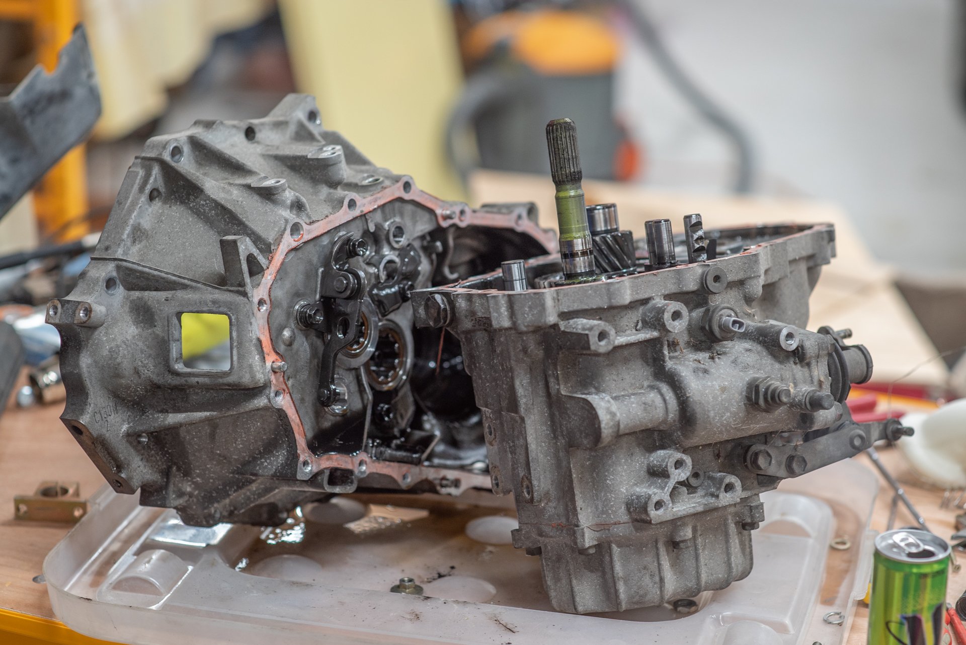
Oh god, cracking the housing would be awful haha. It's a big relief that it's all together and goes through all of the gears fine. Super keen to take it for a drive again soonish! I've got fingers and toes crossed that the synchros in this box will be a little better than the other one. If the C152 synchros are the same as C56, I might punish myself some more and rebuild that other box with the good synchros. As that original Echo box just shifted so damn good, only problem was that everything else about it was awful haha.
-
Ahhh yeah but only because I've gone through the 1000s of hours of suffering to get to that point haha. I got the gearbox back together today, but man it fought me all of the way. I finally got the little reverse lever thing in place, then was ready to lower the box down and it would only go so far then stop. I wrestled it for ages, couldnt figure out what was stopping it from going in any further. I gave up and pulled it all back apart. I found that one of the cylindrical bearing (balls? cylinders?) tipped over out of its cage, so the end of one of the shafts was sitting up on it. Once I put it all back in place, it all went together and dropped down in place without too much protest. So I jacked it back up a little, gooed it up, and job done! Thank fuck for that. Super chuffed to have this all back together though. Even with the difficulties above it was much less intimidating than I thought it would be. But I still hate working on gearboxes. Maybe it's like wiring, where once you cross a particular threshold of experience and have the proper tools it start being less awful to deal with. Next job is to pull the other motor and box out, while I wait for oil seals and gearbox oil to turn up. (from somewhere... Havent ordered yet)
- 1536 replies
-
- 15
-
-
So the ABS pump/ECU plug has got a suspiciously large amount of pins on it, so I've been thinking maybe it has some speed outputs that are unused. So I traced the pins... Everything's accounted for, apart from 3 mystery pins which are blanked off with rubber grommets. All of the "blank" pins are blocked off on the plug so you cant add terminals, but, there are actually pins on the pump itself under the plug. So first thing is to investigate those three that just have rubber grommets blocking them, but are pinnable with some extra bits of wire. However I believe this pump is actually a Bosch unit. So it's got terminals that are unique to the pump that I dont have any spare of. I might get another pump itself so I can investigate more easily what all the other unused pins do. The "data connector" pins run to the OBD2 plug. It's tempting to try decode this, as it would most certainly contain wheel speed information for sake of troubleshooting. But by the time it's gone from sensor, to ABS pump, to an arduino, to canbus, to ECU. It's probably too slow to be useful compared to using for inputs on the ECU directly. If there's nothing suitable that comes out of the pump itself, plan B is to tap into wheel speed signals then use a frequency divider as per what Stu says. Which is fine but it would be nice and tidy if there was a solution straight from the pump itself. For the more immediate situation however, I got the speedo drive thingy on. new bearing on. I have done a test fit reassemble. Definitely a bit tricky getting that reverse lever thing back in the right place, but it's doable. Fingers crossed I have this all back properly together tomorrow. The only thing I'm now missing is axle seals, but at least I can get the box all assembled and otherwise ready to go.
- 1536 replies
-
- 24
-
-
I have been doing some more homework on this. The sensors are two wire, so I've been assuming they are a variable reluctor. But turns out that its not uncommon for ABS sensors to be a 2 wire hall effect sensors that output square wave. If this is the case then I assume my life becomes a whole lot easier. Will do some testing with the scope.
-
I'd love to have speed signal from wheel sensors, because then I can use proper traction control features in the ECU. Buuuutttt The problem is that the high tooth count on the ABS rings means the ECU tops out its ability to read frequencys quite low (something like 80kph or 100kph max) If I cut down the tooth count to suit the ECU then ABS doesnt work properly, and honestly it's bloody good having ABS at the track after being used to not having it (and flat spotting tyres) I have looked at how I could bodge the speedo ring back on, but realized if it flies apart at some point it's about 50x more effort to fix the problem at that point, than it is to just have some extra patience and fix it now. So I have ordered a replacement bearing. One good thing is that it's considerably easier to press the old one back off when there's no speedo gear on it. Also I cant drive this car at all until I've got a working alternator, and I wont be able to pick up the new bracket until some time after level 4 simmers down. Not that it matters because I cant really drive it anywhere anyway while we are at level 4. Not the end of the world. Taupo Trackday is October 1st though which I've realized is sneaking up! Definitely keen to have the LSD installed well before that, and try get everything tip top reliability wise.
-
So looking at the parts site some more, trying to think of a way I can keep making progress. It turns out there are two bearing part numbers and then two shim part numbers 18.5mm bearing and a 2.1mm shim or 19.4mm bearing and a 1.2mm shim Keen observer may note that both of these added together is 20.6mm So, genius idea! I will pull apart my original echo gearbox which is from 2005 so definitely the later model one, and steal the shim to suit my new bearing. Pull it apart - has the right shim in it. Awesome! So next steps: Step 1: press the bearing shells into the casings - done Step 2: press the bearings onto the diff - done Step 3: Fit the speedo drive gear back on before doing Step 2 Oh for fucks sake
- 1536 replies
-
- 20
-

-
-

-
Bearing situation. Getting the bearings off was a one way trip so definitely no chance of reusing them. It turns out that there's a slight change in gearbox bearings half way through the run of NCP13s (possibly facelift vs not) So on one side of the diff, the bearing is the same between AE111, NCP13, and NCP91. However on the other side, AE111 and early Vitz NCP13 share a bearing part number. Then late NCP13 and NCP91 have a different bearing part number. The early one is 19.4mm wide and the late one is 18.4mm wide. There's a different taper angle on the bearing/shell. Presumably that side of the transmission case is cut shallower to allow for the difference, they definitely arent just interchangable. So I played bearing roulette and ordered two yesterday just before lockdown news... and got the wrong one for that side. But at least I now know definitively what I need.
-
3SGTE in a mini is like a lead tipped arrow with the arrow cut off
-
Yeah it will be a world of difference! Cant wait. It is incredibly frustrating how easy it spins up the front left when trying to get off the line.
-
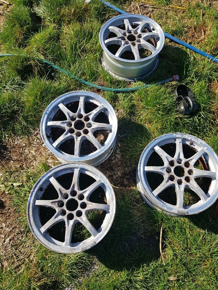
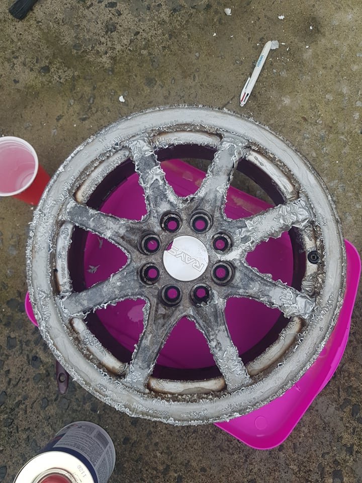
Oh yeah and further to previous wheels chat. Rays wheels come in at 6.0kg per corner. But good enough, could realistically only get 1kg per corner less by spending $$$$$ Still ~12kg total less than ROH wheels. But getting a bit of a refurb as they were a bit fucked
- 1536 replies
-
- 19
-
-
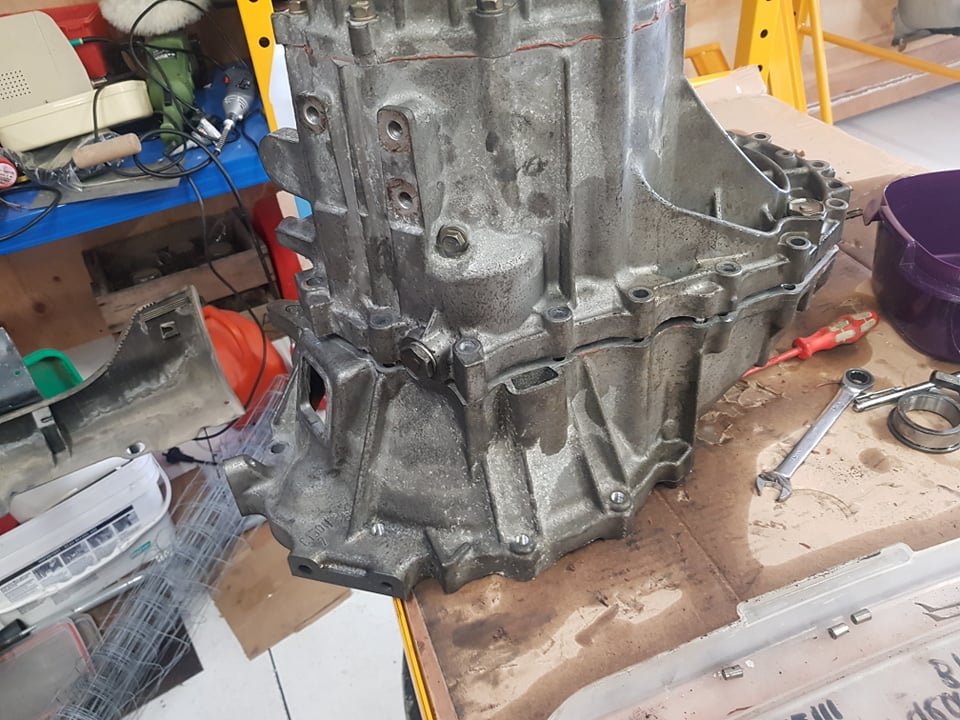
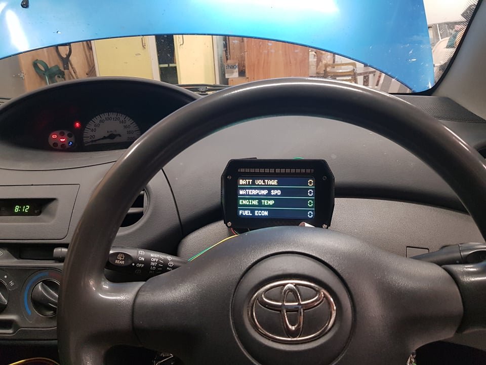
So I put on my brave pants and took my brave pills and pulled my spare gearbox apart... Too easy! I think I've just managed to get some PTSD from the complexity of J160 boxes. But this was piece of cake. I toyodiy'd the gearbox parts to look for any differences, found that the bearings and shells have different part numbers. Some more digging and I found that they have a different size or taper on the bearing and shell, so you need to match them. Otherwise you get this situation where the shell doesnt sit flush to the bearing: So this week I'll pop over to my Dads place and use the gear puller and press to swap the bearings over, then its fairly easy looking to get it all back together. It turns out that some variants of the C series box have a 6 bolt crownwheel, luckily both the AE111 torsen center and the RS box have the 8 bolt pattern. Cant wait to get this new box in, will be awesome. I've also been thinking of some methods for half arsed launch control when I dont have a non driven wheel speed signal. I have setup a timer that resets to zero when TPS is over 80% and vehicle speed is zero. So when the vehicle speed goes over zero, the timer advances and the engine is allowed to accellerate at a specified rate over that time. Then once the timer reaches 4 seconds you get the normal rev limit from then onwards. The other axis will be an input that will come over canbus from my dash, so you can adjust how aggressive it is. I'm not quite sure what sort of time period will be needed yet for this to work nicely. Oh yeah and bodged together a little canbus dash to show some things that you dont get on the main screen. Graduated shift light is pretty sweet. But the main thing is to give some peace of mind about the electric waterpump, with some big flashing warnings if it fails.
- 1536 replies
-
- 28
-
-

-
Nah when it cures normally in a thin layer with fibreglass etc, it cant generate enough heat to get into the run away cycle of blowing itself to smithereens. The cure time of epoxy on a part is way way higher than when your pot of epoxy will go off. This time of year when it's cool you might not have too much trouble with either, anyway.
-
Also if its vacuum formed, then its designed to pull off a single piece solid mold without issues with draft angles etc. So should be pretty easy* *conditions apply
-
Yeah you can do it in bits that slot together. 240 and 110 deg will likely be fine. Main thing is stopping drafts. I've not tried printing the carbon nylon stuff because it's a real ball buster of admin work to keep the matieral ok for printing. You have to bake it before your print it to get the moisture out, then it reabsorbs moisture so quickly from the air, that you need to keep it in a dehumidifier box while it prints. A smaller printer is considerably considerably easier to work with with way less headaches. I'd say 70% or 80% of the prints I do are under 250x250
-
Yeah it's definitely a cool thing to have, I have tits for hands when it comes to fabricating things so it's really bridged that gap for me. And now I think it's got me thinking more about how I'd actually fabricate something, when it seems intimidating when you dont know how to start otherwise. I have a Creality CR10-S S5. So it's a 500x500x500 build size but otherwise a pretty cheap and basic printer. I wouldnt reccomend how it comes out of the box unless you wanted to print PLA only (material that isnt really usable in hot conditions or for things like manifolds) To get it to be able to print stuff like HIPS I needed: -Change to direct drive extruder -240v heated bed -build a shitty enclosure -new controller and firmware that is 32bit instead of 8 bit (It would choke up a bit when there were lots of commands to do quickly) -solid mount the bed instead of springs Probably about an extra $4-500 worth of stuff, and shitloads of time calibrating things. But now it's an invaluable tool for me.
-
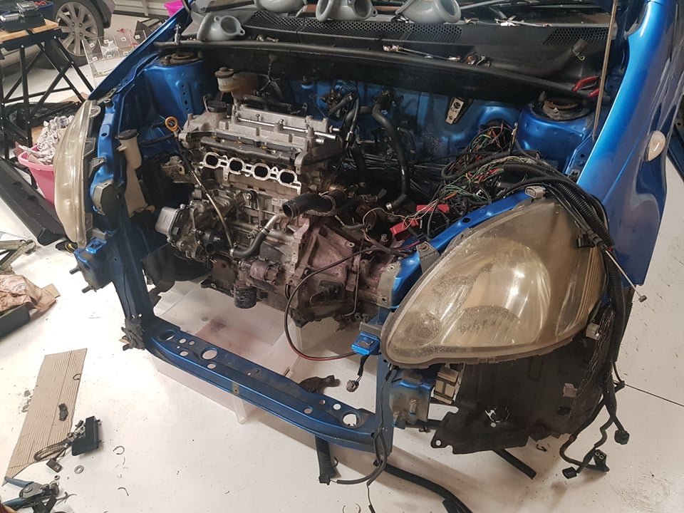
So in echo related updates, Picking up the new wheels from swap meet this weekend, big thanks to @Goat who is bringing them along! I also picked up box full of C56 internals including a torsen LSD. Big thanks to my mate Ken for this. LSD will be glorious! But I have a decision to make. The "proper" way to install it is to sit the box on a bench with bellhousing facing down. Then disassemble the box from the far side and remove the gearsets and detents and everything to eventually get to the ring gear and diff center. But this is like, you've got some food stuck in your teeth but you can only reach it by sticking a broom up your arse. There's a bodgey way where you can remove the front cover only, looks fiddly as fuck but saves a big headache (maybe) So I'll give this method a try on my C152 box first to test the practicality of it. I hate working on gearboxes so I'm torn between taking the long/proper way, or the potentially short but fiddly way. Historically speaking, trying to take any shortcuts usually leads to misery and having to do things the proper way anyway. Also my alternator situation has been nothing short of a miserable headache that's stopping me from driving the car currently. It was fine when I first installed the bracket and tensioner, but it would squeak a little bit sometimes. Eventually my shitty tensioner broke, so I made a better one with the aim of eliminating the squeak. Didnt work, it still sqoke. Rechecked belt alignment, fine tuned it to be as exact as I could. Pinged belt up tighter. Squeals like a stuck pig. Eventually my alternator bracket broke. So I got the local workshop to jizz it back up with some welds. Then it was fine for a little bit, then started squealing in an incredibly annoying manner and hasnt stopped since. I found that the bracket had bent, for I think the same reason it broke initially. The alternator has a sliding sleeve of sorts that pulls inwards to tighten the alternator to the bracket, where the bolt threads in. If it's a bit rusty (they all are) it doesnt move too freely, so takes a lot of force to pull it back in. I CRCd it a bunch and hammered it in and out to free it up a bit. But when you crank the shit out of it to tighten it up, it's trying to crush my bracket before its trying to pull that end bit in. Also I think another potential problem is that the original motor has 3 accessories on it. Aircon pump, waterpump, then alternator. The belt path means theres maybe 190-200 deg worth of belt wrap on the alternator. But if you run just from the pulley to the alternator, there's only ~160ish degrees of belt wrap. So then you need to tighten the belt heaps to try make up for it - then you have issues with things bending or breaking especially when rpm is high and maybe some harmonics stuff coming into play. Then the short belt length probably doesnt help either. So at the moment I'm torn between trying again with another alternator bracket, or just calling it quits on this motor. Evenutally I need/want to get an NHW20 prius motor so I can run VVTI, bolts to gearbox properly, and then I can use the factory bracket to fit an alternator on. With extra belt wrap and belt length because it's back to a mechanical waterpump. But I'd like to compare notes to this existing engine first, hopefully get both on a dyno and see how much difference the compression ratio difference makes (or not) The NHW20 motor is funny because the only thing running off the accessory belt is the waterpump, which then runs on the non V side of the belt. So the only thing running on the Vs of the belt is an idler where the alternator usually goes... But it can definitely fit an alternator there, as the block is the same part number as a normal 1NZ motor. Pretty frustrated at the moment as it's a really unfun sort of problem to deal with, and I dont really have any tools or ability to fix it myself.
-
Do you mean for my manifold, or the other bits? I'm still using the same manifold from day 1, so I'll call that a win. Once I put the carbon on it, it's been fine since then. The only real reliability problem is that my throttles are held in my tapping into the plastic material. If printing another one I'd make the tapped area much longer so it spreads the load more, or design it so steel threaded inserts can be pressed in from behind. To print this material (HIPS) you need a printer that can get the nozzle to around 250 degrees, and a heated bed that can go 120ish. Then you need an enclosure to stop drafts (this is probably most important part) then it's still a bit of a bastard to print haha. Loves to warp. Most off the shelf printers cant go that high for nozzle or bed temp, but these are easy-ish upgrades you can buy for not much.