Roman
-
Posts
6752 -
Joined
-
Last visited
-
Days Won
32
Everything posted by Roman
-
I'm wanting to go through cert process again, but it's unlikely I'll have everything sorted by December. I was hoping to go through a tech inspection so I can make it to OS drags this year, if I can sort everything else out in time.
-
It sounds like the wheels are slowly turning for a rules update around this topic. I mean Toyota started having full ethrottle cars 3 years before Playstation 2 came out! It's hardly a new technology. It's funny going to nightspeed because the late model BMWs with advanced traction control stuff just absolutely rocket out of the hole on street tyres compared to anything else. But that's not really anything to do with ethrottle, it's more to do with DCT transmissions and ignition cut/fuel cut traction control. Ethrottle is too slow to react to be useful at the drags. It's a bit frustrating, but yeah I guess I will just keep pushing to get all the tasks finished to get the car going. Then just talk to a tech inspector and see how I go. It will be a shame to miss participating in OS drags if this is a hurdle. However I can still get a logbook and enter the car into some other events when it's going.
-
Yeah I'm using SW20 calipers at the moment with a Primera disc. But I've got an MX5 setup here I was looking to fit at some point. Going back to a smaller/lighter non vented disc, and better pad options for MX5s. That's one of the most important things for choosing a caliper I think, finding something that actually has good pads.
-
There is an F series that bolts straight in. Mine came from a left hand drive French MA45 Celica. haha! Thanks to @thegreatestben who was wrecking it a long long time ago. Needless to say they are incredibly uncommon, took a fair few years of looking before I found one. (And back when there were a lot more of these era cars around) The only problem with this setup is that it's factory drum rear, so has the skinny bearings. I've got an Estima setup too that I might shorten and swap in at some point. So I can get the big bearings on the axles. As I've worn out these ones a few times already. They start leaking after a while.
-
The axle tramp this car had on semi slicks or street tyres was insane, the shock loading on the drivetrain must have been intense. I am 100% convinced that squishy drag tyres do less damage to drivetrain than axle tramp. The echo as well, on semi slicks it felt like the car was ripping itself to pieces. On drag slicks it just felt like a CVT, but the wheels were spinning instead of gearbox guts. I'm not too worried about breaking stuff. If it breaks it breaks. One annoying thing. I'm just looking to get some clarification around tech inspection requirements. It seems that ethrottle is banned for drag racing tech rules unless it's factory fitted. So that might prevent me from passing a tech inspection.
-
This has an F series diff, which is one size smaller than the Hilux ones. I think it will be fine. I've got some spare axles though, and you can buy aftermarket ones that are stronger.
-
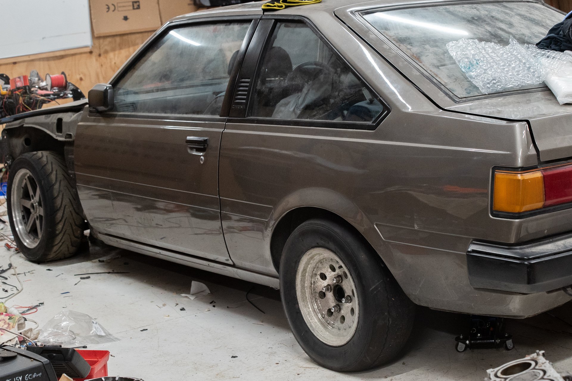
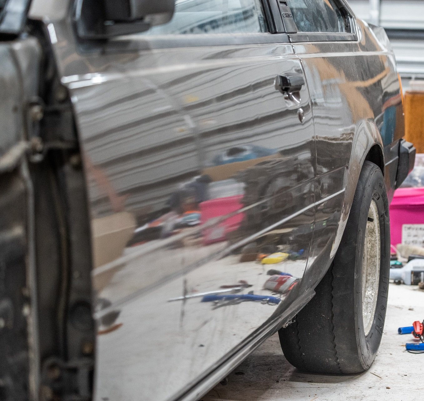
Surprisingly, my current rear brakes fit 13" wheels no problem! I did need to use the spacers to clear the calipers to face of the wheel though. I'm super hyped for drag racing activities! Looks sweet on trailer wheels and slicks. haha. I thought my mate with the 808 wagon was running 1.8 60ft on these same tyres, but he's run a few 1.6s. That is just an insanely fast launch. The best I've ever done in the Carina was a 2.5, best in the Echo on these slicks was 2.09. If I could get below 2.0 sec 60ft in this car I'd be stoked. I'm thinking I'll do my previous trick of extending the bump stops so that it's nearly sitting on them at its resting height, for drag stuff.

- 74 replies
-
- 36
-

-
Yeah they are dimmable and it definitely needs it. On my last one I had an LDR connected so it would dim or brighten in near realtime (dampened a bit) It was amazing, come over a crest so sun is shining on it, could still see it fine. Needs some sort of failsafe though as if it defaults to full brightness at night time itll burn a hole through your head.
-
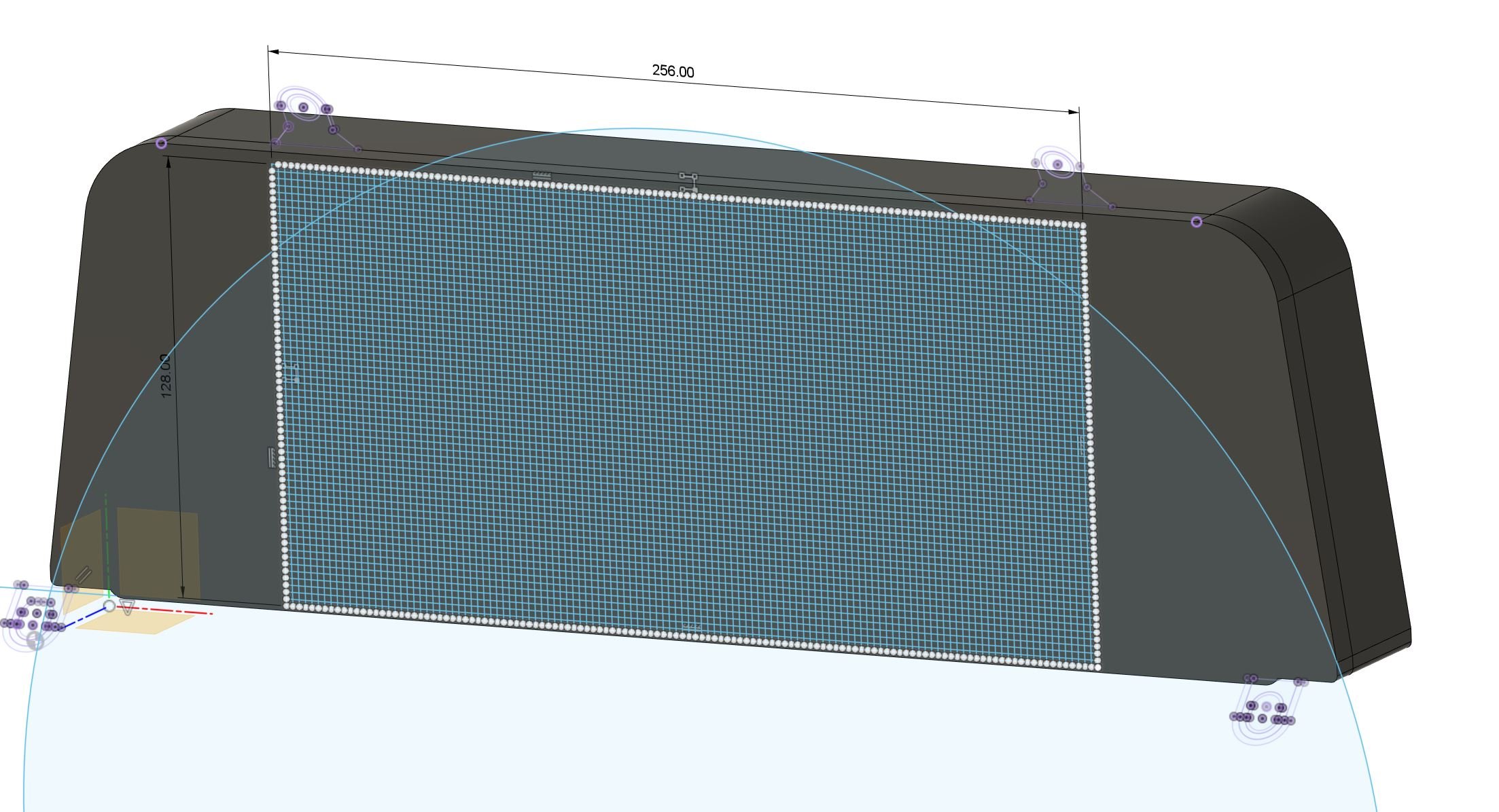
A few things going on. Most of the wiring is tested and working well. A few mistakes I made with wiring order which were easily remedied thanks to being able to repin the sub loom plugs. The TPS on the second set of throttles, runs absolutely nothing like any TPS I've seen before, which is annoying haha. It wasnt simply two voltage divider circuits. It uses some fancy chip that looks at the field lines coming off a magnet that rotates, then draws two sine waves that get compared by the ECU to determine throttle position. Or some crap like that. So, that's off to the bin. I will need to print an adapter to put a second "normal" TPS on there. But it's been annoying that I havent been able to test my ethrottle controller yet. Since it's a small fiddly part that needs quite exact tolerances, I shall borrow a favor from @flyingbrick who has an awesome resin based 3d printer. The dimensional accuracy is amazing, he previously printed me a fitting to go on the end of my valve spring compressor tool. Which worked great, and showed no signs of wear or damage after fitting 24 very stiff springs into two heads. Thanks Nathan! Also, I found a cheap set of bogan spec 13x7 4x114 Cheviot US800 wheels that I can fit my drag slicks onto. So that will be cool. Hopefully I can make it to December OS Drags via tech inspection. Even if it means the car will need to be running with standard cams and the crappy factory exhaust manifolds or whatever. Fingers crossed I can keep the momentum up and get things done in time. Another thing is that a while ago I decided I want to run a digidash instead of a factory one. So I made this which worked out quite well and was cool. But I felt like the styling wasn't quite right, and I somehow wanted to use up more of the space on the sides. But couldnt quite think of how to achieve that. In the meantime, with the Echo. I discovered just how absolutely magnificent it is, to have a graduated shift light where the bars start from each side, and meet in the middle. The accuracy on shifting is really amazing. So I have been looking into how I can incorporate some LED bars into the shape. But, then I went a bit further down the rabbit hole and figure that instead of using an LCD screen (which was 800x480 resolution in the above case) I have found that you can get 2mm pixel pitch LED screens which would be super cool for this I think. So I've found a screen that is 256mm across, and 128mm tall - which is a pretty damn good fit for the carina dash: (The circle indicates the visual block caused by the inside edge of the steering wheel, so outside of that is fairly useless space) Previously I was trying to emulate the sharp edged aesthetic of a fixed segment LCD display. However this will end up looking a bit more... Commodore 64 or something. haha. I'm not 100% sure if it will work out how I'd like, but it will be fun to play around with. There is already a really awesome library written for it, to run on a Teensy 4.0 which can render things crazily fast. One issue with the LCD screen I was previously using is that the refresh rate was fairly crap. Which is why you cant have things like a shift light/bar just represented on the screen. It's too slow. But these LED screens have an insanely fast refresh rate, no problem. So I can incorporate my shift lights directly onto the screen and it will be super fast. Here's a video to get the general idea:
- 74 replies
-
- 26
-
-

-
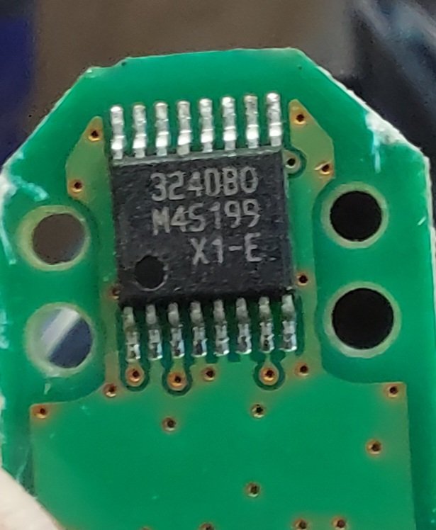
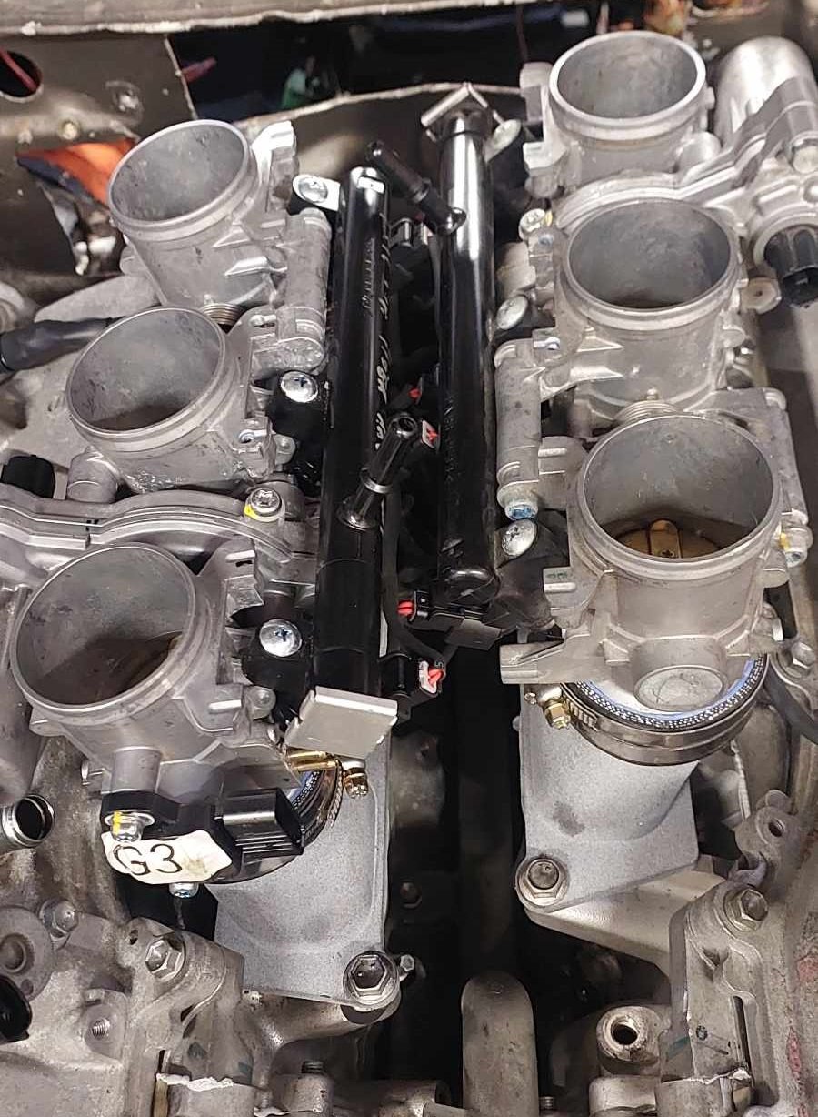
Looks like its a Melexis rotary position sensor. Too complex will adapt a regular tps on.
-
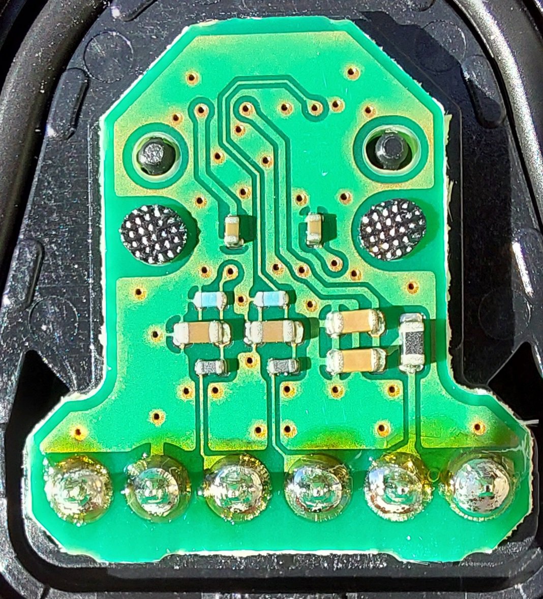
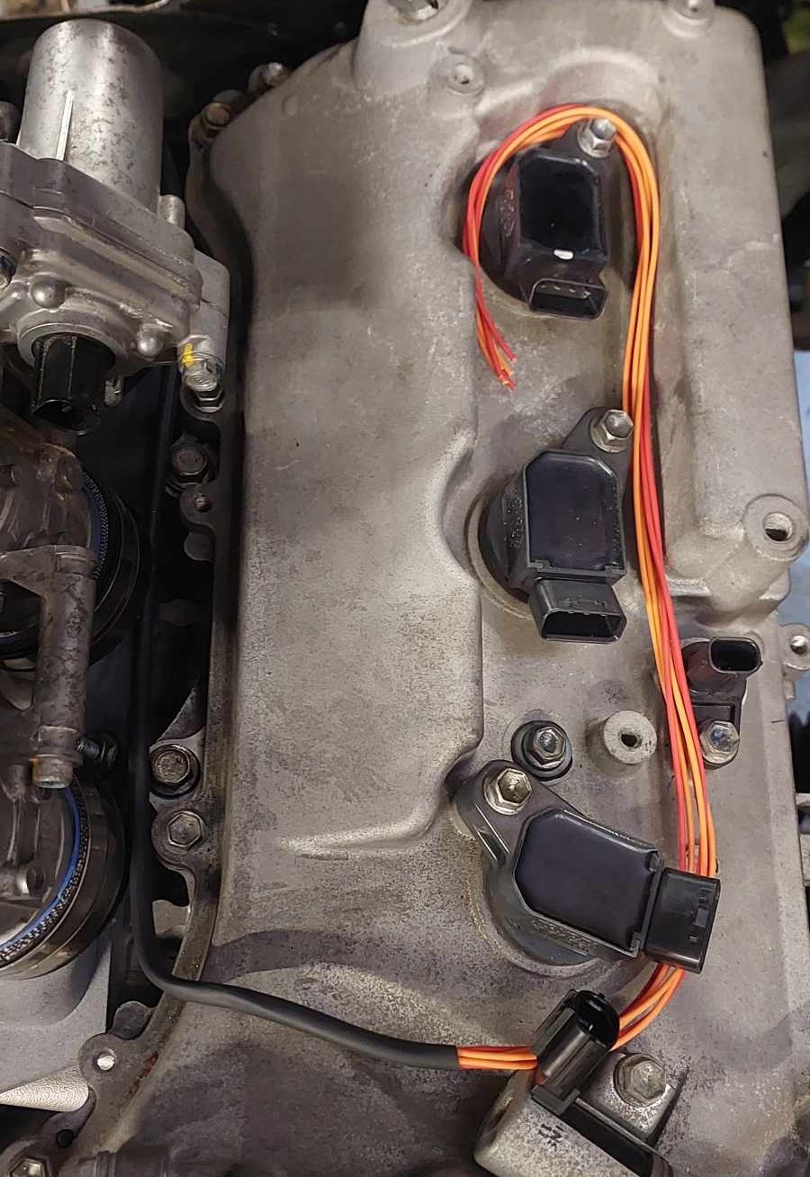
This is the other side
-
Bit of a mindfuck with my throttles. One bank has a 4 pin plug and normal voltage divider circuit. Second bank has 6 wires, and i assumed 2 separate 3 wire circuits. But nope, its got magnets & shit. Im thinking its hall effect but i have no idea how the wiring goes. Or if it would likely output a variable voltage or a frequency or whatever. Anyone (by which i mean @h4nd ) have any idea?
-
Yeah that would be interesting to see, especially with a surface mount thermistor on the runners. Because the metal throttles on mine would get icy cold.
-
Yeah I'm not going to run outboard injectors. But always interesting to hear some other perspectives if he's keen to yarn about it! It might be to do with that when you slam throttles shut, then it generates vacuum. So it lowers the boiling point of fuel so it clears off all of the residual fuel on the walls pretty quickly. But if it's ahead of the throttles, it just sits there. I ran the echo with fuel rail mounted ahead of the trumpets, and surprisingly it idled absolutely fine. At full throttle the fuel map didnt even need any adjustments either. But transient throttle was really gross, and I dont know if there's any good way to make that better. There werent any apparent benefits from it though, car wasnt any quicker. I still think the only good reasons for outboard injection is for engines that have poor mixing inside the cylinder (Super short stroke) so they need to premix it more in the intake. Which is why some engines seem to get gains from it, others dont. Because you're only "gaining" what a longer stroke motor achieves inside the cylinder anyway.
-
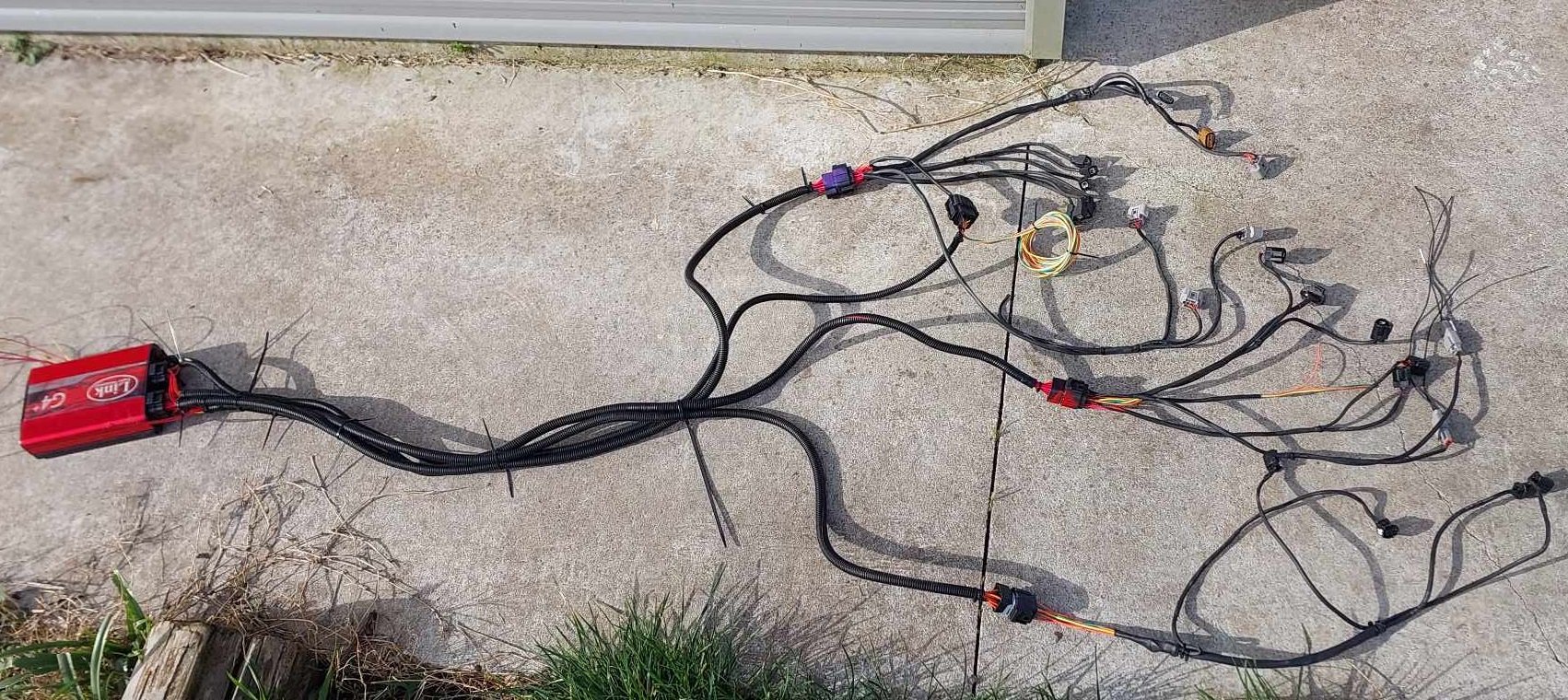
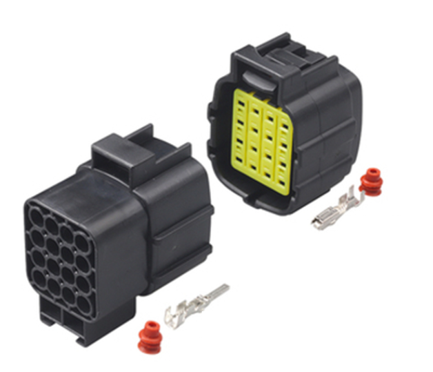
My loom is mostly finished. Will give it a few tweaks to make it look tidier but happy with how its turned out. I still need to plug it all in and verify that everything works / wired to the correct place / etc. Which takes some time. I've got two more plugs to do, that tie into the body loom and my fusebox arrangement. So I need to try remember how all of that works. I've given up on finding e-throttle plugs, so I just slotted some terminals onto the pins inside. Filled up the plugs with liquid plastic from the 3d print pen. Then heat shrink over the top, and silicone in the end. Feels nice and secure, hopefully works good. Will probably do the same with the 2nd TPS that I cant find a plug for.
- 74 replies
-
- 32
-
-
Yeah lots of interesting things in those pics. I wonder if thats just lighter or more reliable than a bucket setup?
-
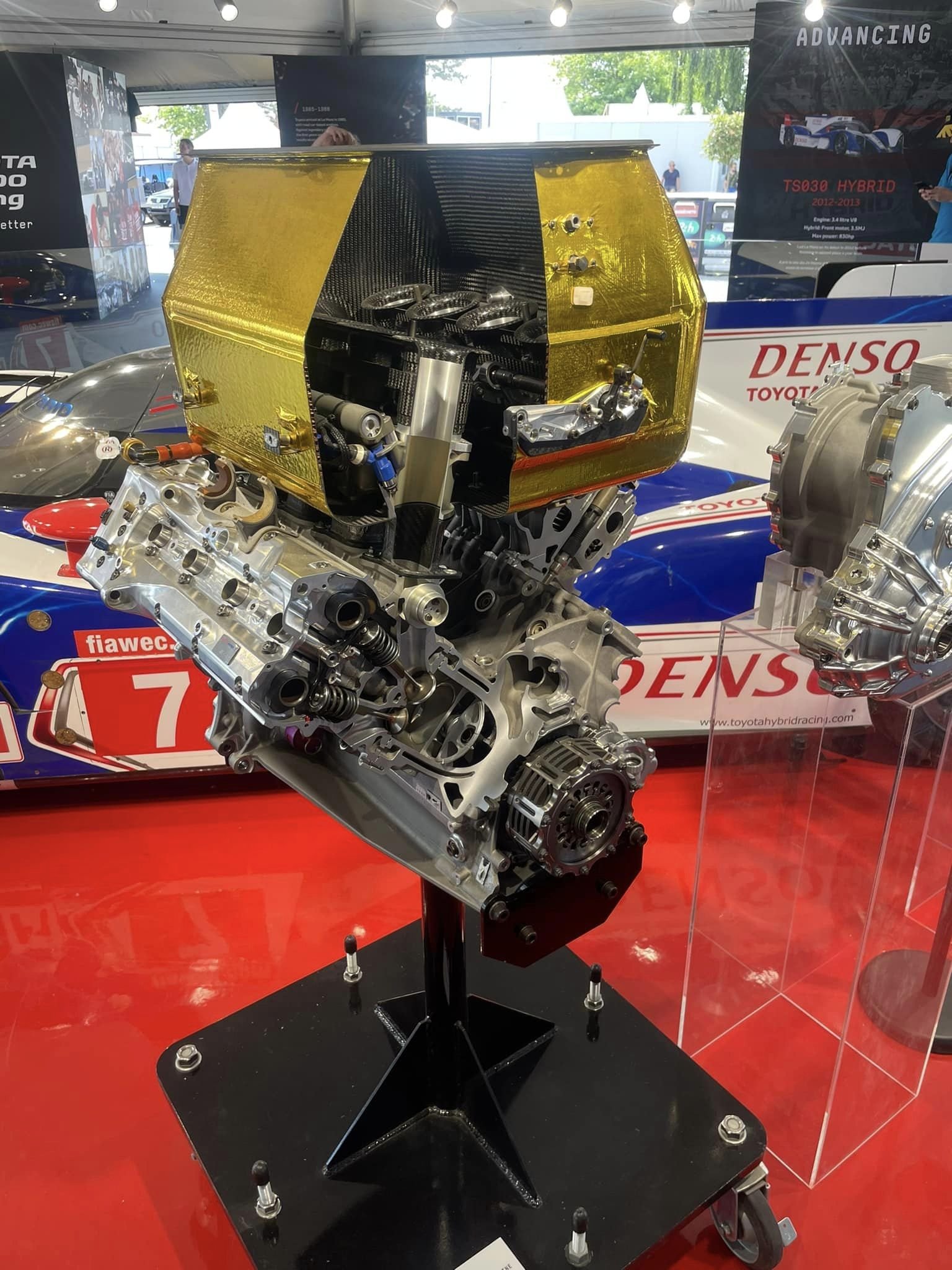
Hey, thanks for following up! I cant remember the exact details or where I saw it. But I remember someone put a car on the dyno where they could hold the load steady. So they ran a butterfly throttle setup, then took the butterflies out and reran for zero difference (just controlling engine speed with dyno) Like has been evident from a lot of KPRs testing, there seems to be littler harm in just oversizing the intake diameter. Seems like the intake is most sensitive to changes at both ends (and length) but not much of the middle area seems to make too much difference, within reason. However - Barrels are still cool, nice and compact, and potentially easy enough to manufacture for a one off experiment. I found the picture of the barrel setup in the V8 race engine.
- 647 replies
-
- 11
-
-

Discuss here about Yoeddynz's little Imp project...
Roman replied to yoeddynz's topic in Project Discussion
I came for the motor updates, but stayed for the MSpaint diagram -
True, but Al's mum does this 4 times a week. Yeah I am now convinced that a lot of companies like ARP simply buy a factory head bolt, then remake it as a stud without any testing. With the 1NZFE (sorry to pollute with Toyota chat) if you buy the ARP head stud kit. Then the VVT solenoid doesnt fit anymore, and it breaks off the end of one of your fucken cams when you torque it up. Have heard similar reports from some other engines. This is an awesome build. It's awesome to see some RFB stuff done properly.
- 44 replies
-
- 12
-
-
-

-
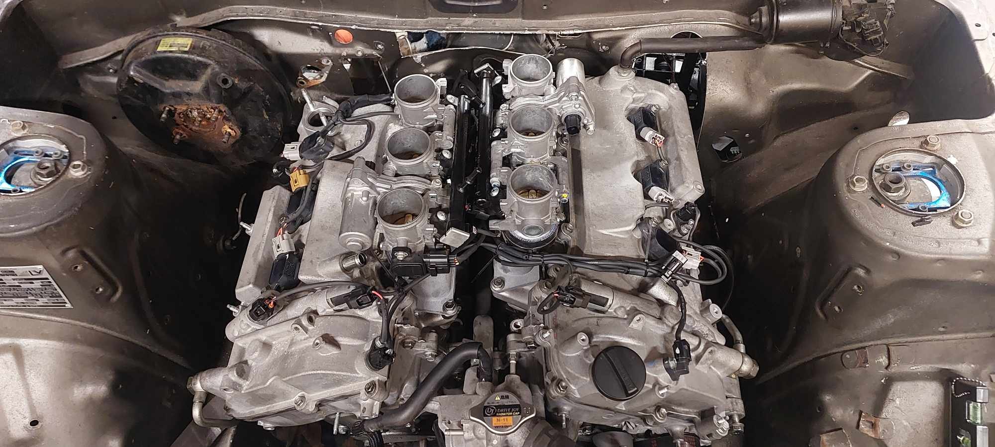
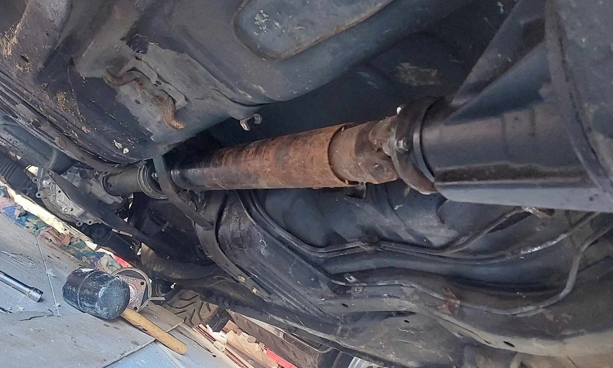
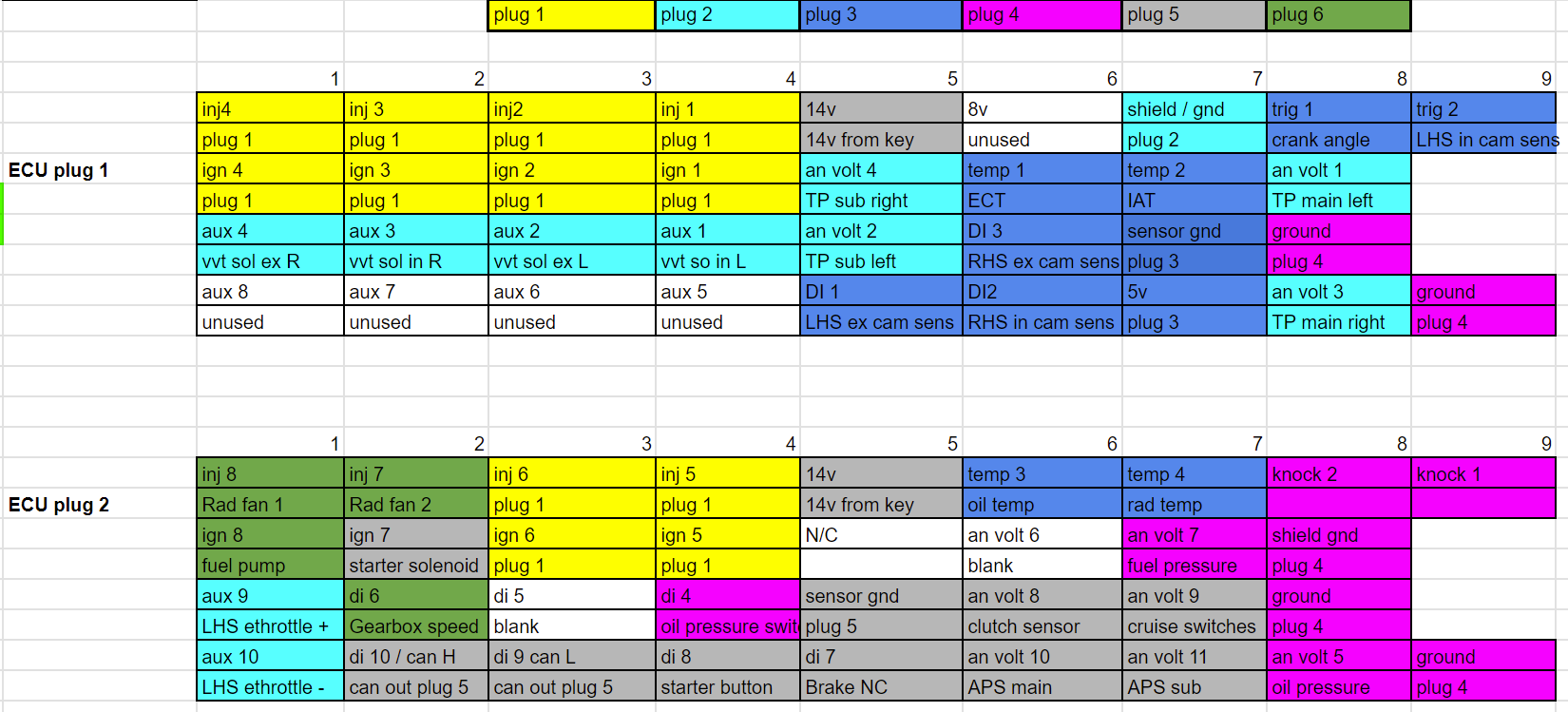
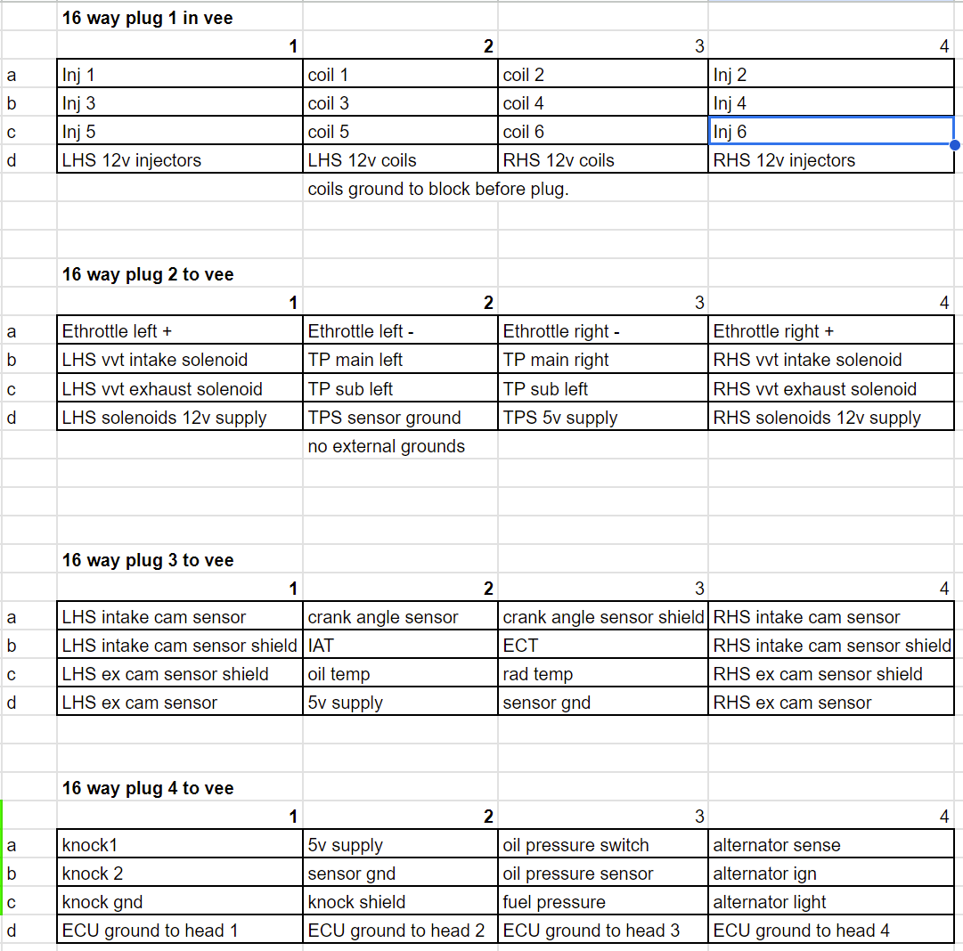
I managed to get the radiator sitting a little lower, so I actually think it will be okay even when engine sits down a bit more. I had a mix and match of various driveshaft pieces, and have managed to put something together that is the right length. Sweet! The UJs seem okay but I should probably get them rebuilt so I dont have another incident. breaking the front UJ at ~80kph was scary. I've started on the loom. I'm gonna have 4x 16 way connectors that live in the vee of the engine, like this: then 2x 12 way plugs on the cabin side that connect the ECU to other stuff. What I found on the last loom that I made for the echo. Was that although I tried to make things tidy, the plugs into the ECU were messy because things unnecessarily crossed over a lot. So for starters, just trying to allocate everything to the 4x plugs. In a way that makes sense for position in engine bay. And keep the higher voltage stuff away against shielded signal wires or whatever. Then I've just allocated everything fairly randomly to relevant pins on the ECU and see how it lays out. Then reorder things so everything is grouped together as much as possible, so the plugs dont become a god forsaken mess like every other time. This has paid dividends as it made it easy to see that if I just swap around input 1 for input 5 (or whatever) then the grouping improves considerably. Also, it's made it way way way easier to actually make the loom - Firstly because it's broken down into 4x sub looms and each of these are smaller, less intimidating tasks. Then secondly the main branch of the ECU into the engine bay is just a straight run ending in 4x plugs. Rather than branching out to everything. So it's way easier to test and trace the individual sections. I've already finished the first sub loom, for injectors and coilpacks. Fairly quickly because it's so much easier when you're working to a plan. Maybe this is why wiring diagrams exist? Who can say? Injector wiring looks fairly discrete which is good. The coilpack wiring is a bit more obvious, (waiting on some more terminals to finish it) but should hopefully still look nice and tidy. These days I prefer to just stay with more thinner branches rather than trying to incorporate everything into one. Partially because I always end up chopping and changing my looms around. But also 4x smaller branches end up considerably more flexible and easy to position. As I'm not using tefzel wire that easily slides against itself to make super flexible motorsport spec looms. (TXL is a cheaper automotive spec alternative) Hopefully I'll get most of this smashed out fairly quick once some extra terminals turn up.
- 74 replies
-
- 35
-
-
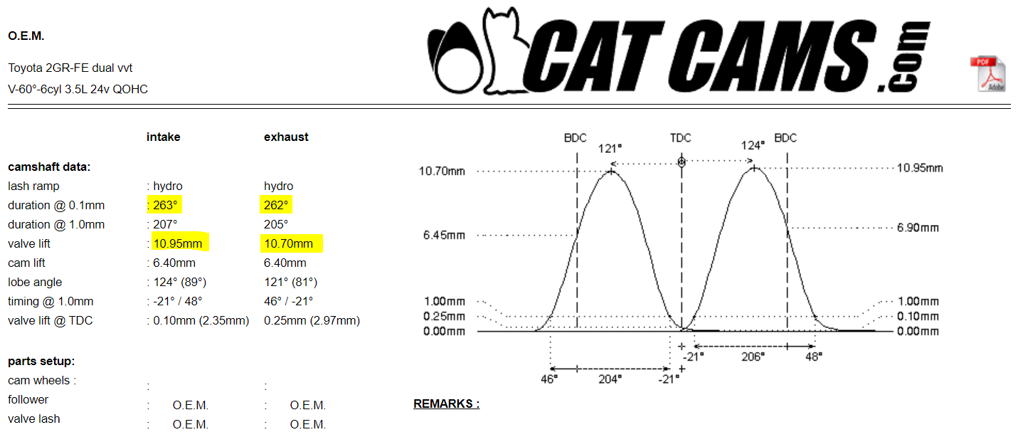
Yeah thats interesting! Like if there was a measurement for "Duration at 70% or greater lift" the numbers would be way different between those two. Although, probably dont need to make things even more complicated haha.
-
Cam duration specs are definitely interesting (by which I mean, confusing!) So I thought Kelford makes the biggest duration cams, they list a 280 deg with 12.7mm lift. However Cat Cams do a 295 deg, with 13mm lift. Sounds great! Well, comparing the lift at 1mm is interesting because they're near identical on the intake side, and the Kelford exhaust side has more duration. Which is likely what would be good for these tiny exhaust valves/ports. Despite 15 more degrees at 0.1mm, there's only 3 degrees difference at 1mm (which realistically, you're not flowing anything before that) So I guess the 295s would ramp down onto the seat nicer, but, effectively the same apart from 0.7mm extra lift. Which is nothing to sneeze at, but I think the cat cams are reduced base circle regrinds. With some mixed reviews on the net. Kelfords might be too, I'm not sure. But if they're cost neutral I'd rather go with Kelford option.
-
DABUZZ'z 1971 Mazda Capella RE + New 74 RX4
Roman replied to dabuzz's topic in Projects and Build Ups
Hey look so I might have done some bad wiring ages ago, but I'm better now! Just putting finishing touches on this new loom.- 107 replies
-
- 15
-
-
-
Actually, I dont know. It doesnt say on their website at all. that would make sense though.
-
I found somewhere that listed the specs for the factory cams. For context, for the Echo, I bought the largest cams available - 264 deg, 9.5mm lift. Compared to the factory intake cam on the 2GR is 263 deg, 10.95mm lift. So this might run better than expected even with standard cams to begin with.


.jpg.912bb3040822a564b02b2569c7cd2d47.jpg)