Flash
-
Posts
1614 -
Joined
-
Last visited
-
Days Won
2
Everything posted by Flash
-
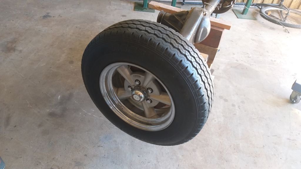
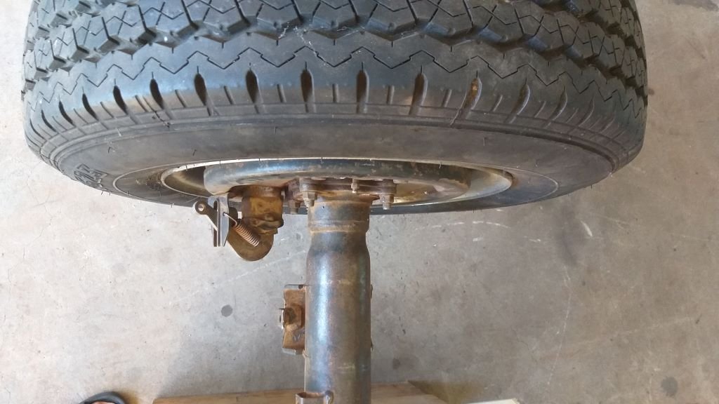
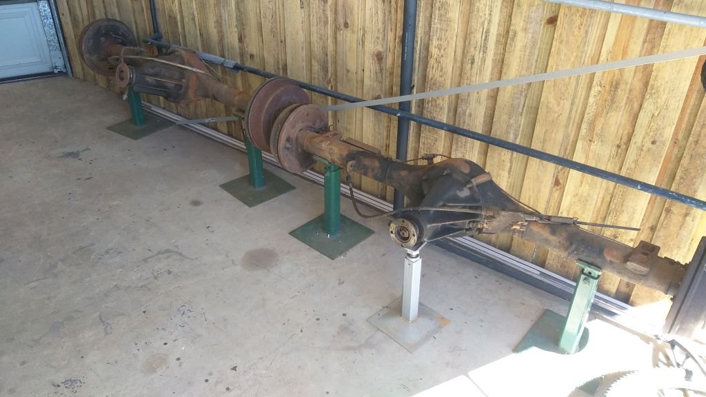
Rear axle alignment – Chapter 1 I previously mentioned that my mock up rear axle was a bit skew on its mounts, so I need to come up with another way to get the alignment spot on. Apart from the fact that I am a total noob when it comes to swapping in different rear axles, I’m thinking that the fact that I don't have a perfectly level welding bench or similar working surface is causing a wee bit of a challenge. When I did the mock-up, I recall battling to find reference points on the axle that I could work off as nothing seemed to be perfectly uniform. What I need for my next attempt is a different approach, so I’ve come up with the idea of using the wheel mounting face on the brake drum as my reference point on each side. My cunning plan is to bolt a wheel on and then use an appropriately wide straight edge across the back of the wheel to determine the position of each spring perch. So, started off by bolting on one of my mag wheels. Instant fail. The bloody wheel doesn’t have enough back space.

-
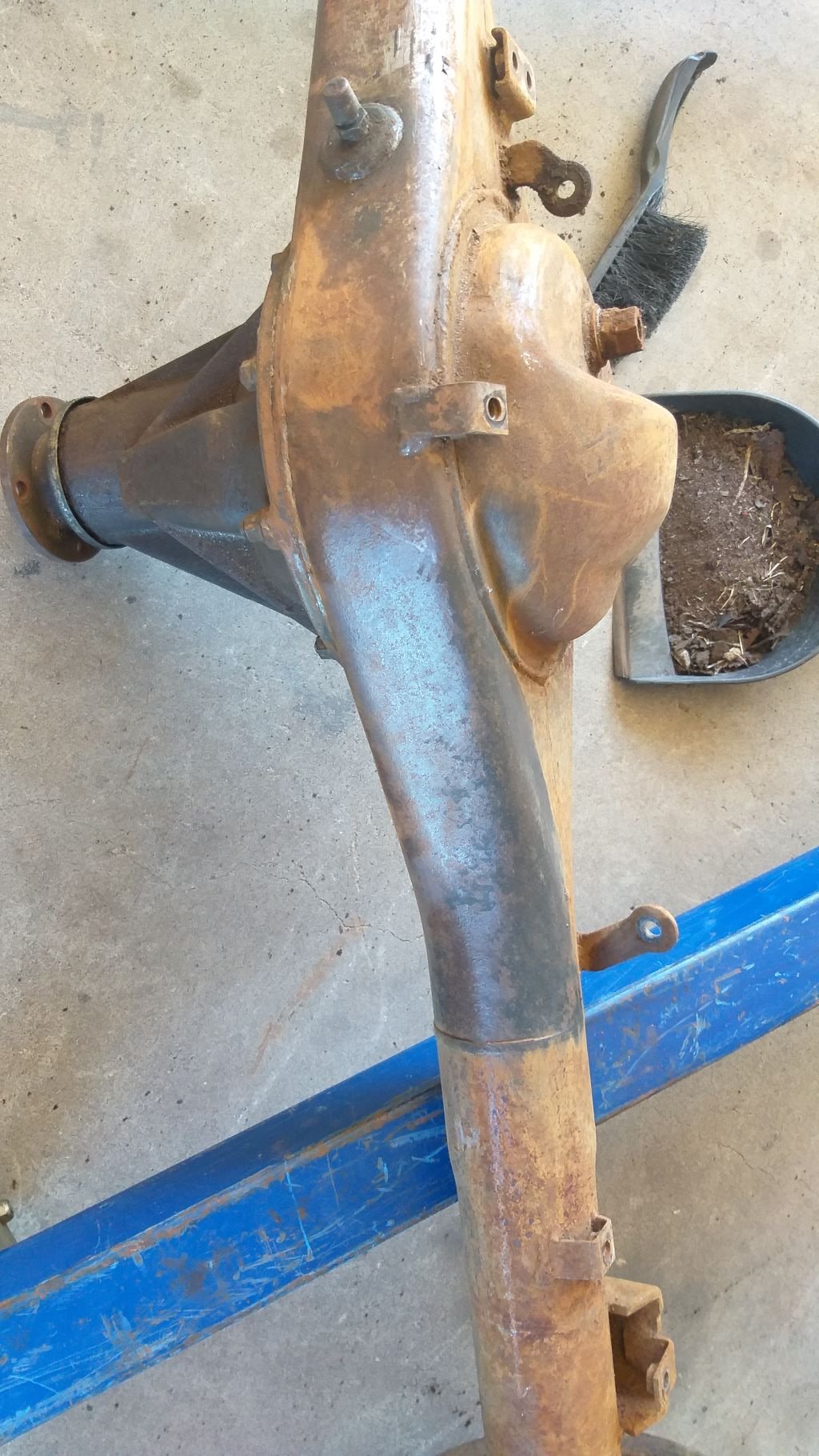
Spent a few hours scraping 40 odd years' worth of crap off the Toyota rear axle. Then made a start on giving the whole thing a once over with my small wire wheel. More of the same planned for tomorrow.
- 715 replies
-
- 10
-

-
And in other news, it took me the whole morning to carve out a pathway through all of the crap in my shed to get to my original Thames and the spare Toyota rear axle. These are now languishing under the back carport. Plan is to swap the Thames spring perches across to the Toyota unit and again I'll give it a good clean and a paint before final assembly. Whilst the existing rear axle that is in the van is also a Toyota unit it was only fitted for mock up purposes and is slightly on the piss, so hopefully my second attempt will be spot on and I can then fix the alignment on the original so I have a spare.
- 715 replies
-
- 11
-
-
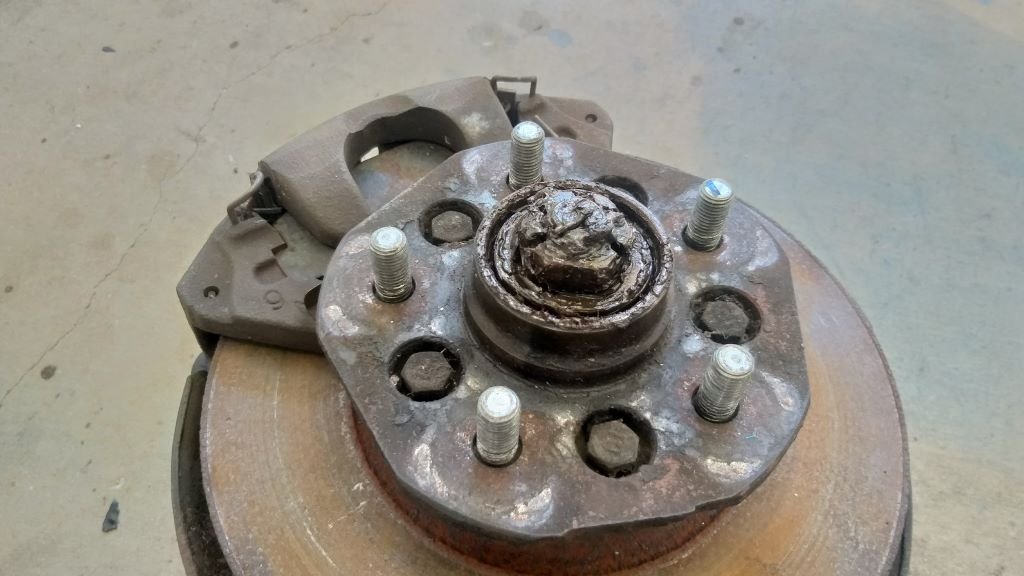
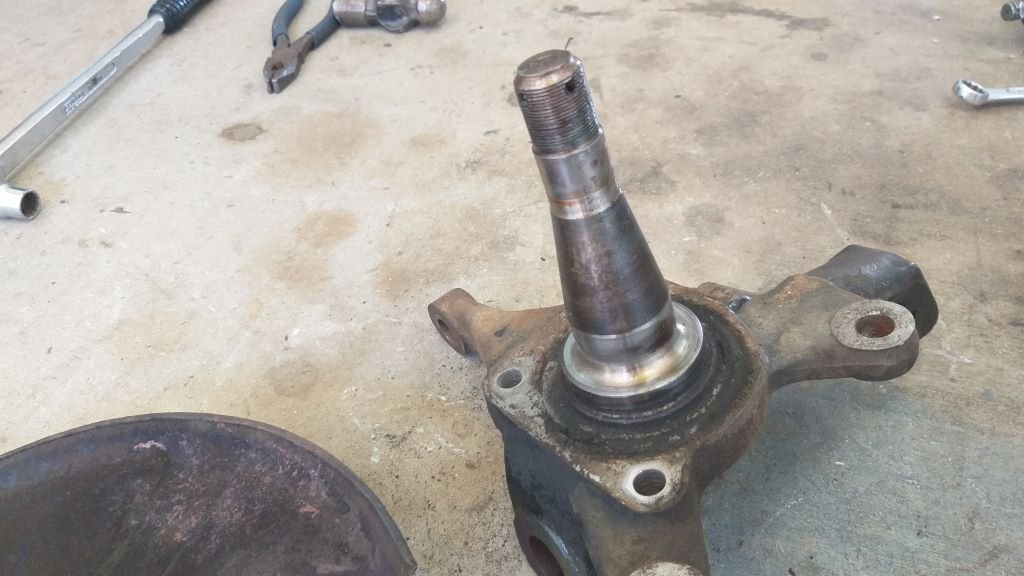
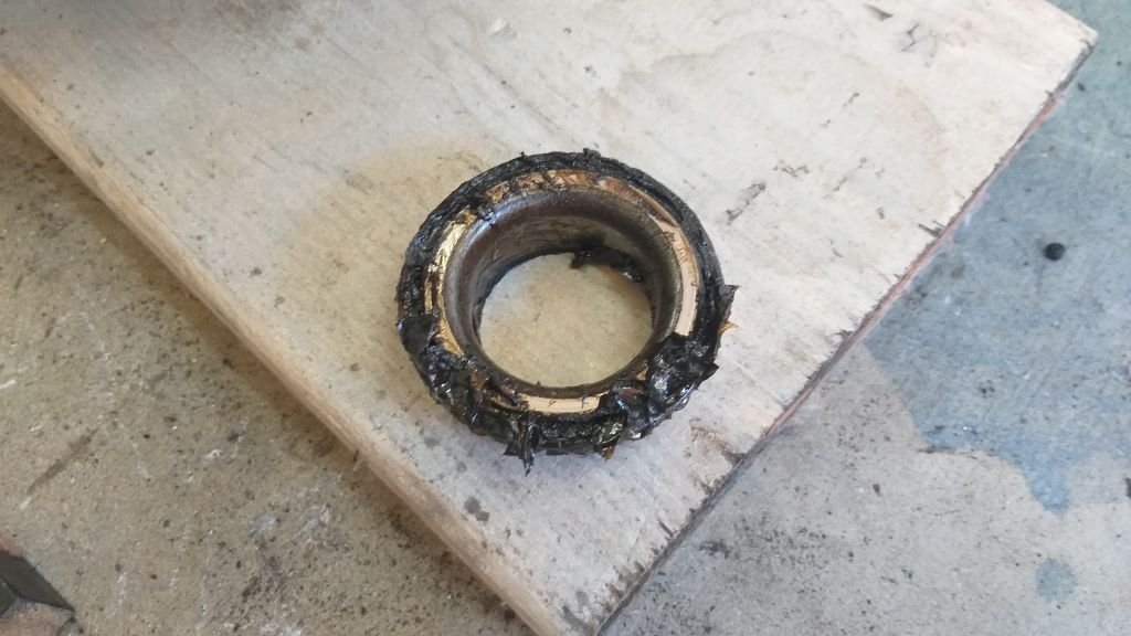
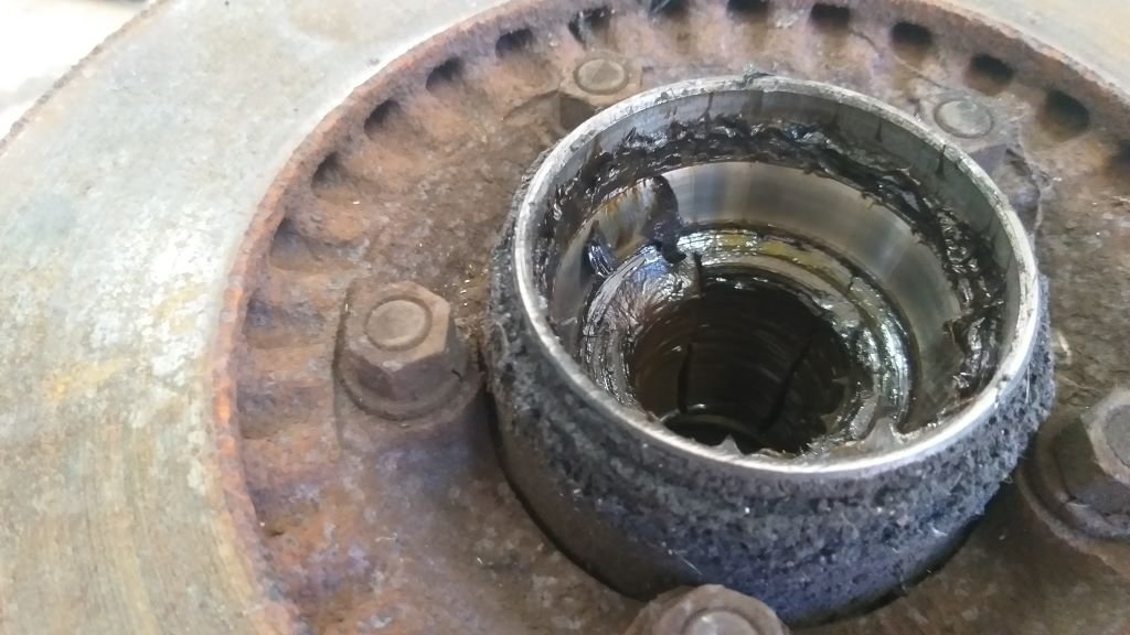
I've started giving the front and rear axles a bit of loving. First job was to strip down the front stub axles and brake assemblies. Popped the first dust cover off the first of the L300 stub axles and there are definite signs of a lack of regular maintenance. Dirty looking grease and a few "hot spots" visible on the stub axle. I can't do much about the hot spots so I'm just going to have to hope that a freshly greased set of new wheel bearings will delay any further damage. There is a 1mm lip on the disks, but I may as well chuck on a fresh set with new pads while I'm about it. Will give everything a good degrease and a quick spritz of satin black before I re-assemble.
-
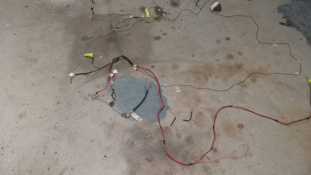
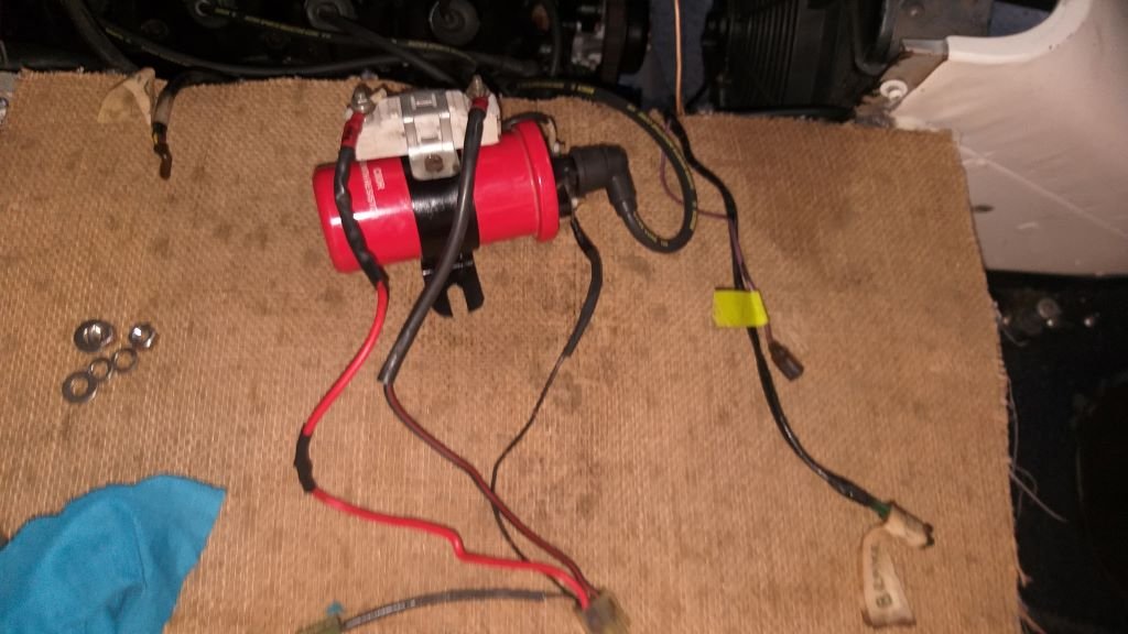
Well, it's been a week full of mundane jobs on the Thames, but I'm slowly moving towards engine fire up day. Today I started grafting in some of the HiAce engine bay wiring, mainly the stuff for the coil and its ballast resistor and the carby related wiring. The jury is still out on whether I'm going to keep the factory Aisan carby with its electric choke and all of its emission control equipment, but I'll keep that wiring intact for now. My cert guy says all that is needed is a PCV valve and a charcoal canister on my fuel tank vent, so I'm thinking about upgrading to a 32/36 Weber further down the track. Some photos of the extra spaghetti being added to the pot:
-
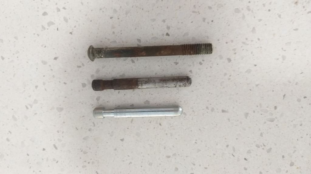
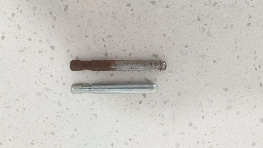
Clutch woes - Chapter 3 Grabbed the crusty looking original slave cylinder push rod and slapped it in place. Gave the pedal a push and I could feel a slight bit of resistance just before the pedal hit the floor, but clutch still wouldn't engage. Feeling pretty confident that I was moving in the right direction I rummaged around in my parts bin and uncovered an old brake push rod. Not sure where it came from but it's about 10mm longer than the crusty original. Slapped it in and called Mrs Flash out to do the pedal thing while I manned the pry bar and .... success! And the pedal feel is amazing. What a bloody relief. Comparison photo of the three rods with the longest and crustiest one now being the weapon of choice. I'll give the pushrod a few tweaks and a clean before calling it done Thanks for reading.
- 715 replies
-
- 15
-
-
Clutch woes - Chapter 2 Just to recap I'm running a Hillman Imp master cylinder with a HiAce slave cylinder. I'd previously worked out fluid volumes to come up with this combination, so my first thoughts were that maybe I had cocked up my measurements somewhere along the line. So, I moseyed on over to my shed and dug around until I found the original Toyota clutch master and slave cylinders. Stripped the originals down to re-check my measurements, but my calcs are spot on. Now something that I had noticed when I assembled the clutch was that there was quite a bit of play on the slave cylinder push rod. While I had the original push rod handy, I thought I'd compare it to the new one that came with my replacement slave cylinder and ..... The new one is 9mm shorter than the old one. WTF.
-
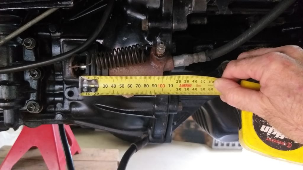
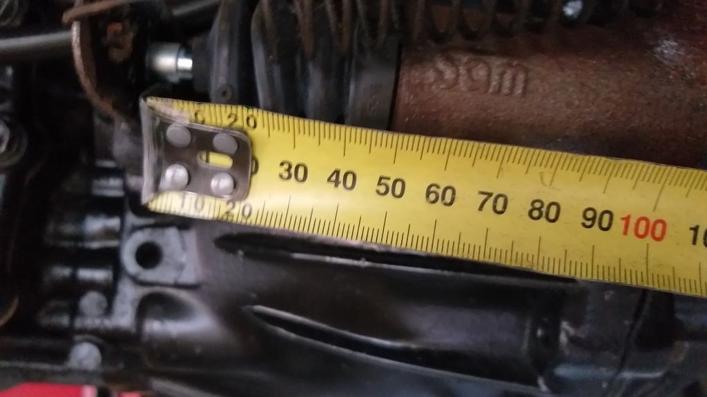
Clutch woes - Chapter 1 Had one of those "oh no" moments earlier this morning, but luckily I managed to avert a crisis. With the engine and gearbox now bolted back in, I thought I'd put my new clutch setup through its paces before going any further. Quickly fitted the hydraulic line and gave the system a bit of a bleed. No leaks so that was a relief, but the pedal felt a bit iffy. Threw the drive shaft in and slapped the gearbox into gear, then with my pry bar on the main crankshaft bolt I got Mrs Flash to depress the clutch pedal, my hope being that the crankshaft would rotate once the clutch engaged. Instant fail. Bugger. Gave the pedal a try myself and it felt really soft. Gave the system another bleed but no air was present, so that's not the issue. Sat down for a bit of a think. Then grabbed a measuring tape to check how much throw I was getting on the slave cylinder push rod. Turns out I'm getting 13mm of clutch fork travel when pedal is fully depressed. Seemed a bit short to me, but what do I know. So I ended up posting a quick question under general chat to see if anyone could confirm.
-
After morning smoko, I was itching to get the engine and gearbox back in. So, this happened:
- 715 replies
-
- 11
-
-
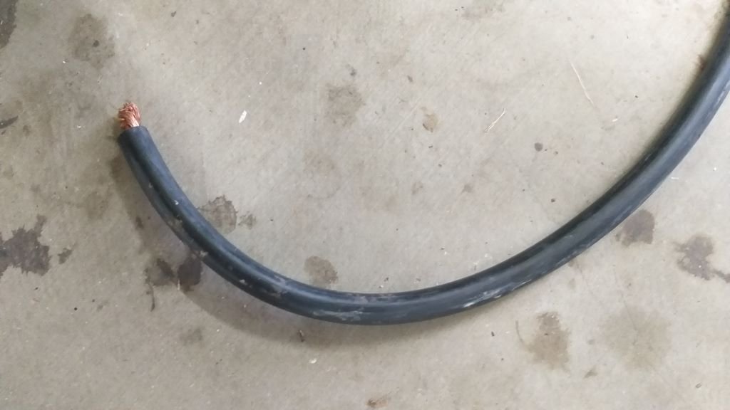
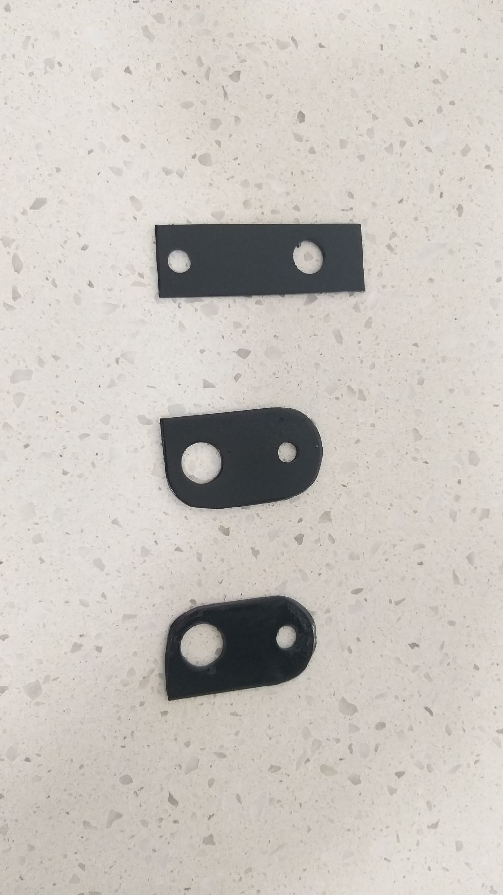
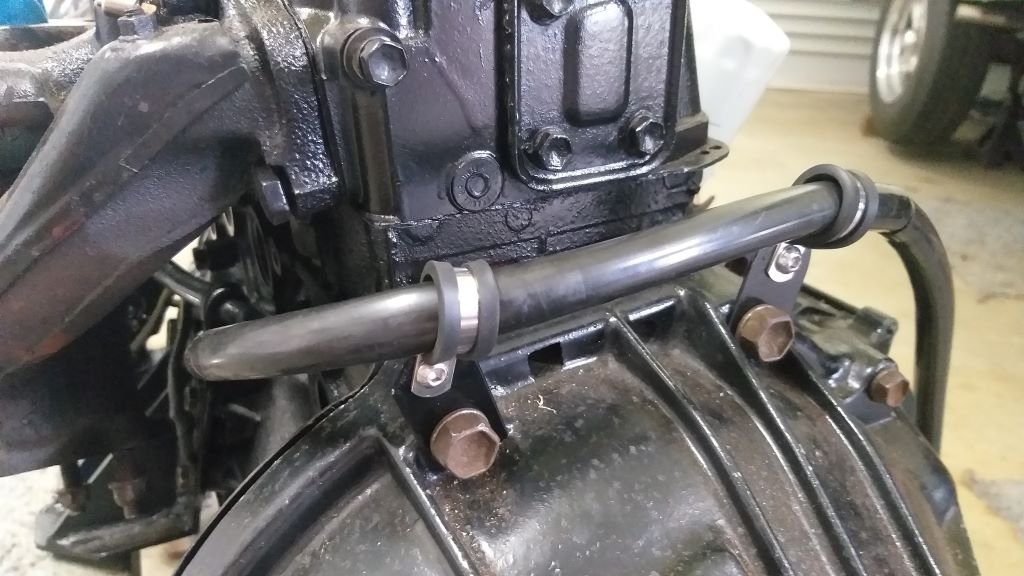
I'd previously harvested a beefy battery cable from my Starwagon donor van that will work nicely on the Thames. The main cable has to traverse the engine as the battery is located behind the driver's seat and I wanted to make sure that it wasn't running too close to the exhaust manifold. Scratched my head for a few minutes then fabricated a few small holding brackets that should keep the cable safe. The bigger bracket bolts up to one of the engine mount bolts and holds the cable midway between the engine block and exhaust manifold and the two smaller brackets attach to the uppermost bellhousing bolts so that the cable loops over the gearbox before coming up through the floor just behind the seat. Mounted the holding brackets then attached the battery cable to the back of the alternator. Fitted a short earth strap too while I was about it. And that's another small job ticked off the list.
-
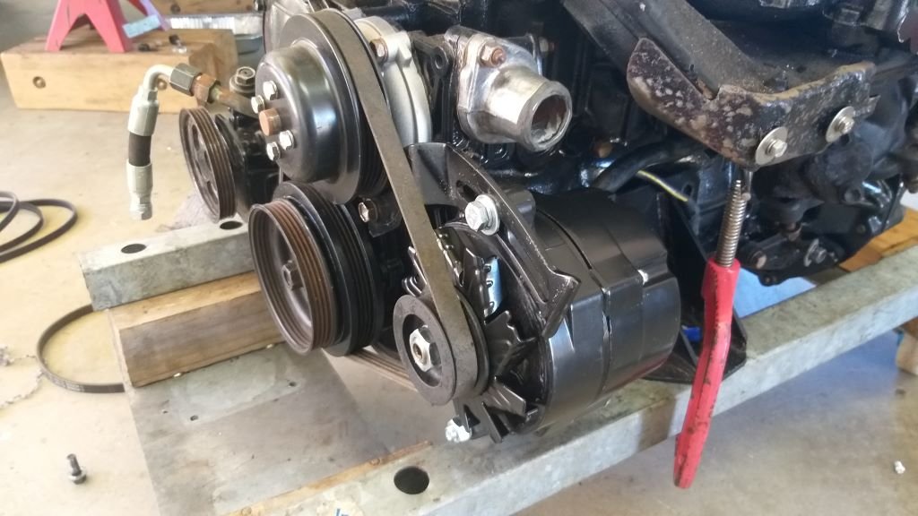
Alternator upgrade - Step 3 Next step was to bolt the alternator into position. I had to muck around with a few spacers to get the belt perfectly aligned, but its looking good now. Just need to chuck a few wires on this puppy and I'll call it done.
-
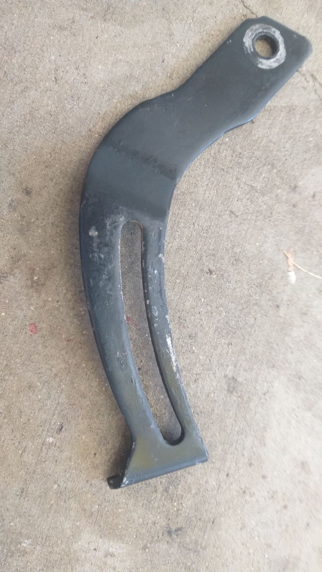
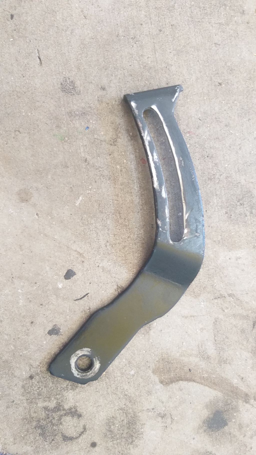
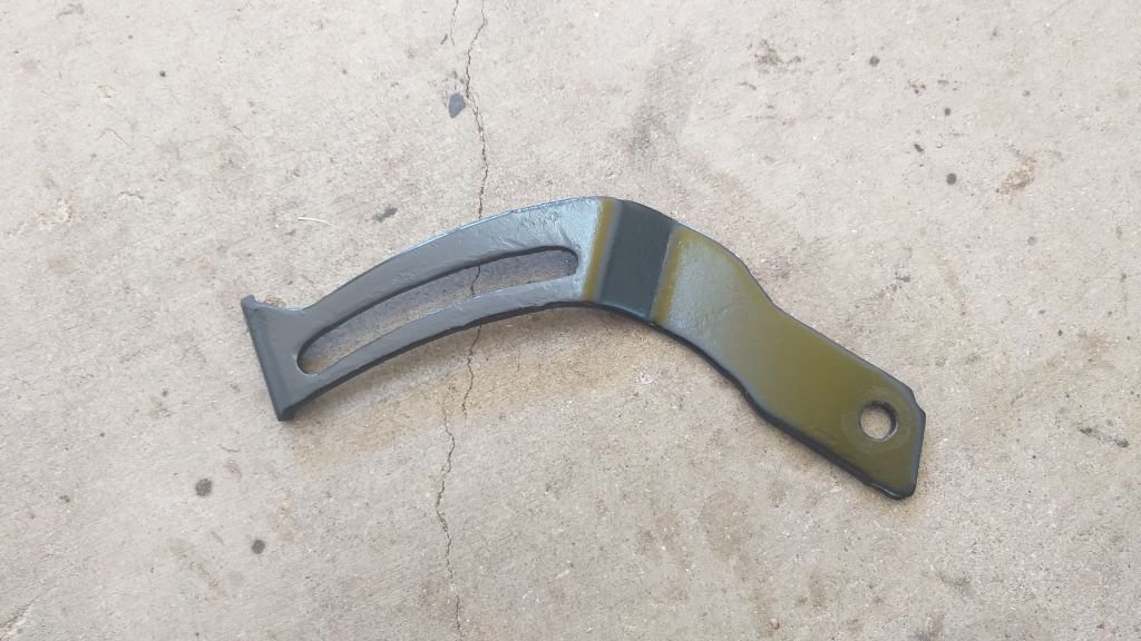
Alternator upgrade - Step 2 Next step was to widen the curved groove in the adjustment arm as the fixing bolt on the Ford alternator is a bigger diameter than the original Toyota one. Gave it a tickle with my dremel and then quickly slapped on a bit of satin black to disguise my butchery.
-
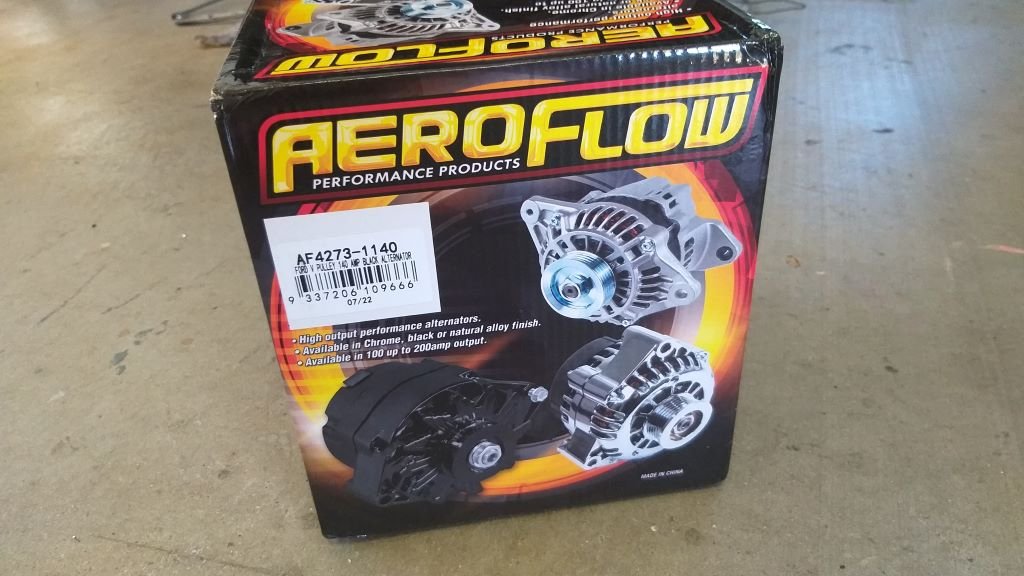
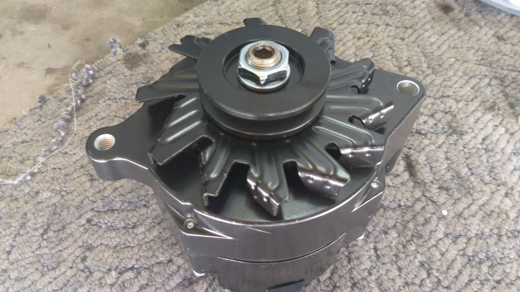
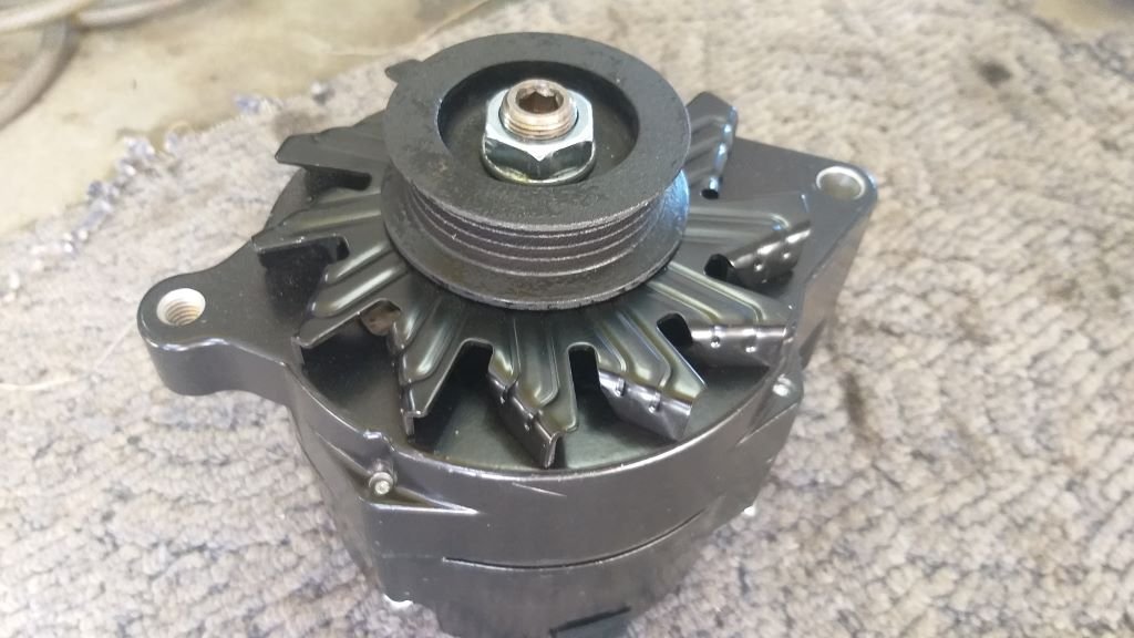
Alternator upgrade - Step 1 Earlier this week my 140-amp alternator pitched up which is pretty exciting as fitting this is the last step before the engine and gearbox go back in. First step was to swap out the single V pulley for the multi-v that I harvested from the standard Toyota alternator earlier in the piece.
-
Thanks for the suggestion. My engine is pretty stock apart from a 282 cam, so I'm probably not getting any real benefit from the current tri Ys either.
-
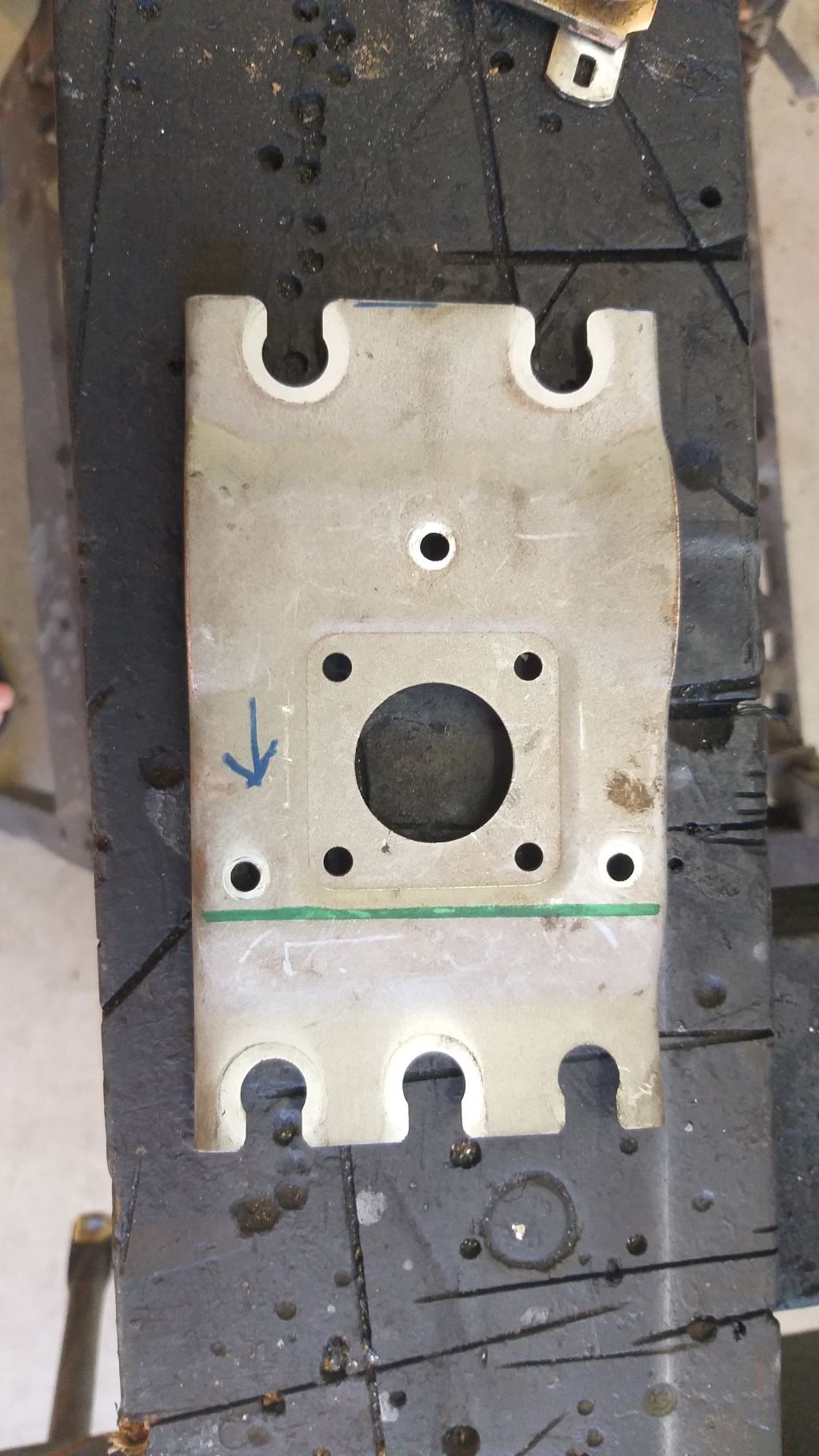
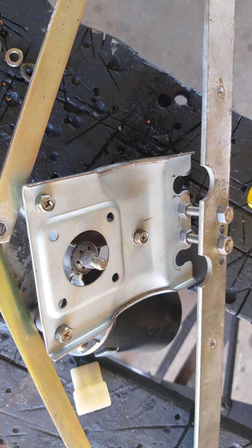
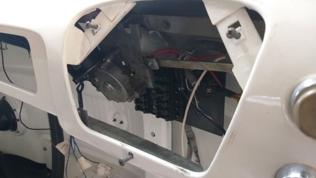
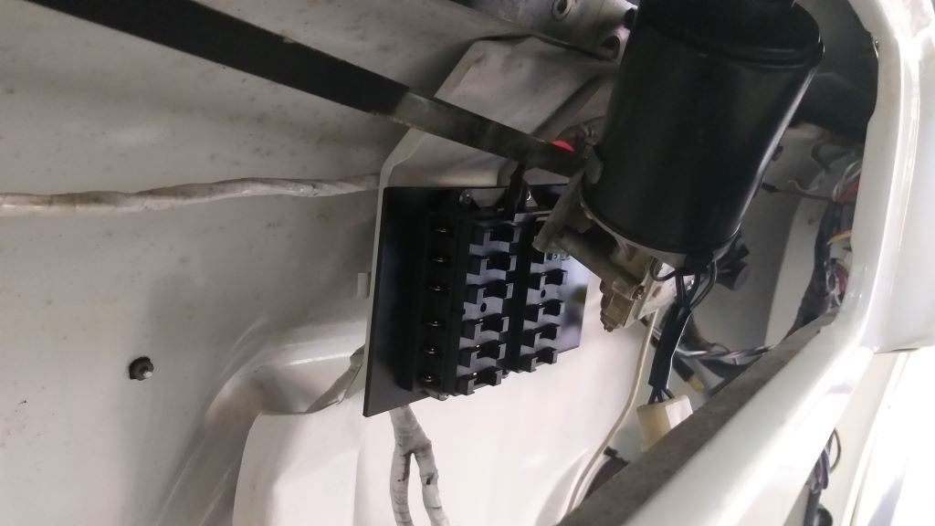
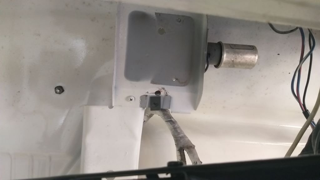
Wipers - Chapter 6 Thought I'd perform a little "proof of concept" with my harvested wiper bits. First order of business was to mate the Thames pivot arm to the L300 one. The centre to centre measurement provided by Sandy is 24.5mm. First challenge was the bend in the L300 arm which happens to be right where the Thames pivot pin needs to be located, so I ended up bending up a L300 replacement pivot arm with an offset bend. Figured I'd use aluminium for the test as it was soft enough to cut its own little spline to match the motor's output shaft. Then I reversed the Thames arm and temporarily bolted the two arms together. Last step was to modify the L300 wiper motor mounting plate and bolt it to the Thames mechanism. It took a bit of fine tuning to get the position perfect. The trick is not to overdrive either of the end swivels otherwise you get a jamb up. Used some extra nuts on the bolts to get the spacing between the output shaft and the mechanism spot on. Bolted the whole lot back into the van, chucked the wiper arms on and gave it a whirl. Sweep angles are spot on, instrument cluster fits perfectly and for the extra bonus I'm able to retain my recently fabricated fuse boxes. Only snag is the glove box inner which needs the uppermost corner tweaked to clear the wiper motor, but the jury is still out on whether I plan to retain the factory glove box, so I'm not too fussed about that. Next step is to try to figure out how I wire up the wiper park feature, but I'll ask Uncle Google to help me with that one. A few photos for your viewing pleasure:
- 715 replies
-
- 12
-
-
I'm keen to hear how you get on with sorting out your header leaks @Geeas I'm still battling with mine. I'm about ready to chuck the buggers in the bin. Apart from leaking the right hand one is almost hard up against the starter motor and although I have massaged it a bit and wrapped the starter it still soaks up enough heat to get "lazy" when hot starting. The left one is also dangerously close to the power steer hoses - as you recently discovered too. As you know they are an absolute bitch to pull off as there is hardly any room between them and the shock towers. I'm thinking about going back to a set of cast HiPo manifolds. My usual supplier stocks the aftermarket ones and rates them. I've put it on the back burner for now as the logistics of getting the car to a muffler place to modify the exhausts to fit the manifolds just seems too hard at this stage. But I've got to say that I'm getting pretty tired of breathing in exhaust fumes. Kinda dilutes the fun of cruising around in the old girl.
-
Wipers - Chapter 5 Sandy pointed out to me that the mounting angle for the new wiper motor is critical. Straight down and the wiper motor sticks out below the dash line. Too far angled one way and the glove box inner will no longer fit. Too far angled the other way and the wiper motor clashes with the back of the instrument cluster. It's going to take a bit of working out. Pity I hadn't thought of doing this before I reinstalled the steering column and handbrake mechanism earlier this week. Anyhoo, onward and upward so I set about stripping everything out one more time, including the instrument cluster. Oh, and just to add insult to injury it looks like my newly fabricated fuse and relay panel will also be in the way...... ho humm...... so that came out too. Blank canvas once again:
- 715 replies
-
- 11
-
-
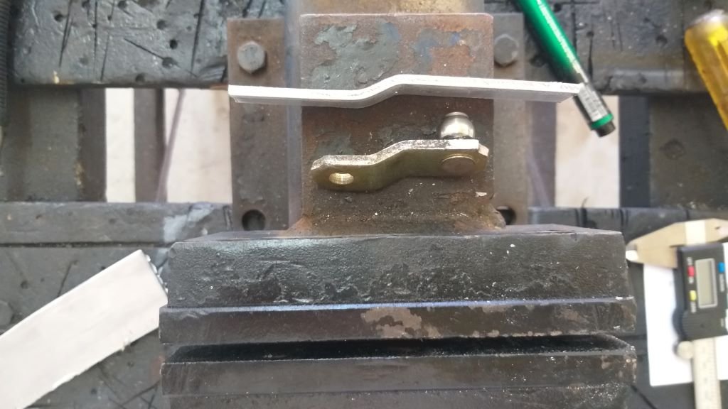
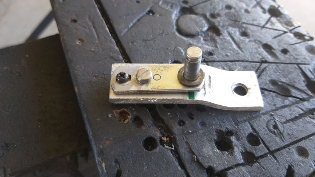
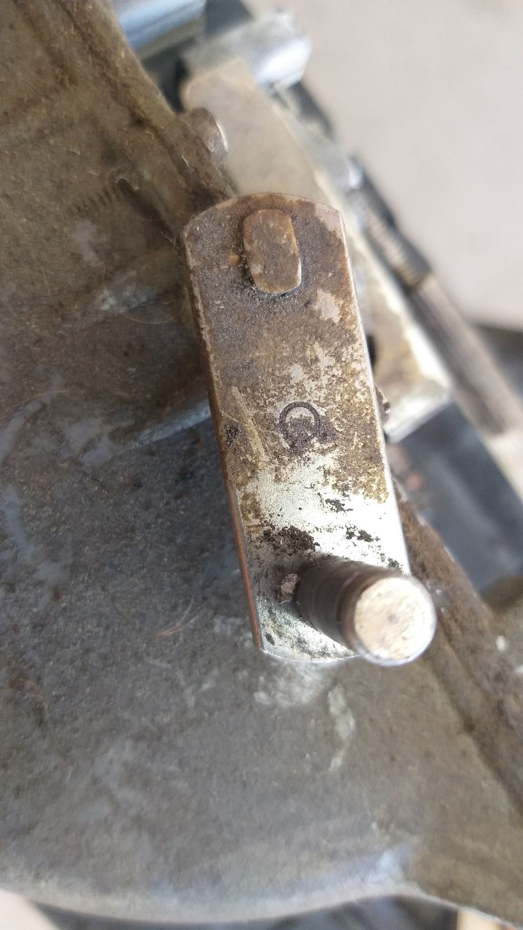
Wipers - Chapter 4 Next step was to remove the pivot arm from the L300 wiper motor as the ball joint is no longer required. This was a lot easier as it sits on a spline so just loosen the holding nut and hey presto:
-
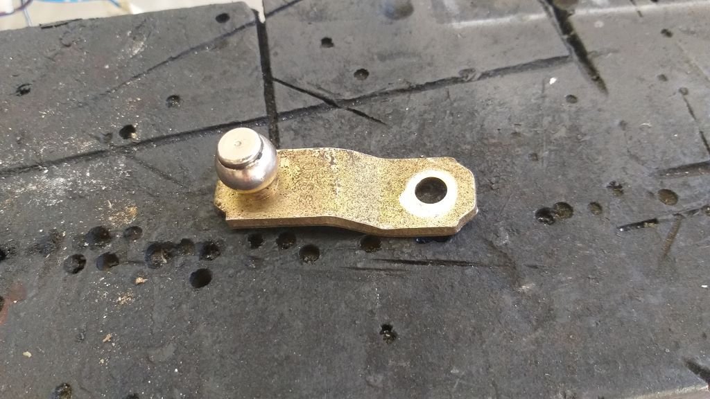
Wipers - Chapter 3 With the L300 wiper motor now being the weapon of choice, I started to work through the detail of the conversion. And again, the information provided by Sandy has been absolute gold. Sandy usually harvests the little pivot arm off the original Thames motor as this matches the rest of the Thames wiper mechanism. According to Sandy this little arm measures 28.75mm from pivot centre to centre. I cuddled down with my vacuum wiper and vernier and sure enough Sandy is 100% correct. First order of business was to harvest this little pivot arm.
-
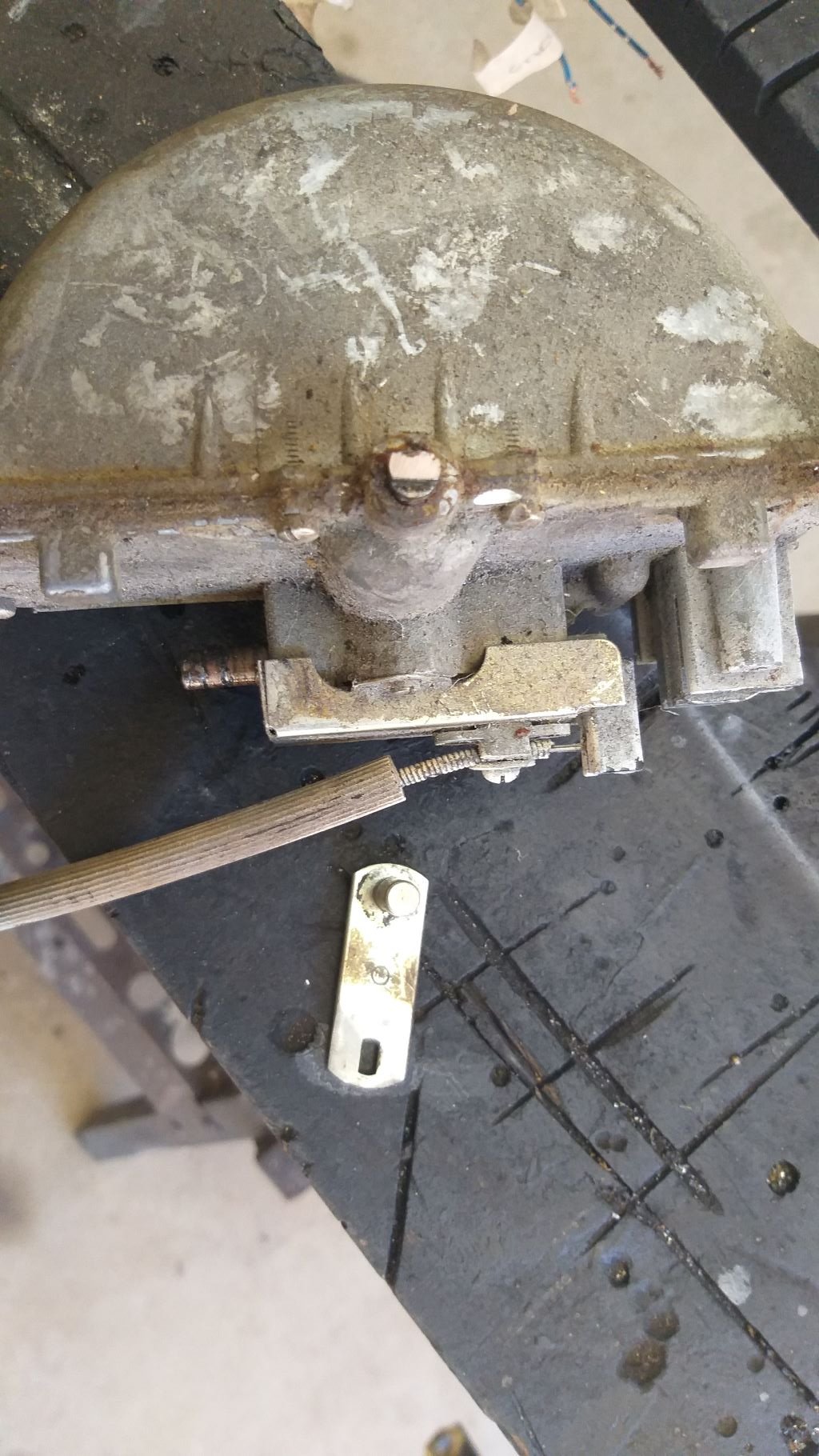
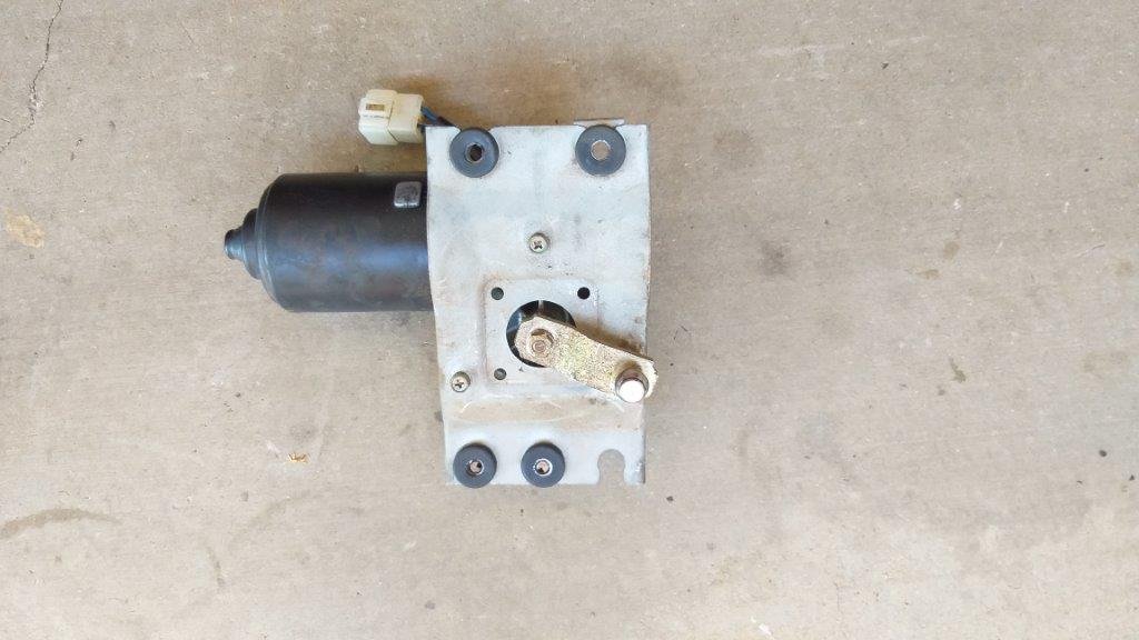
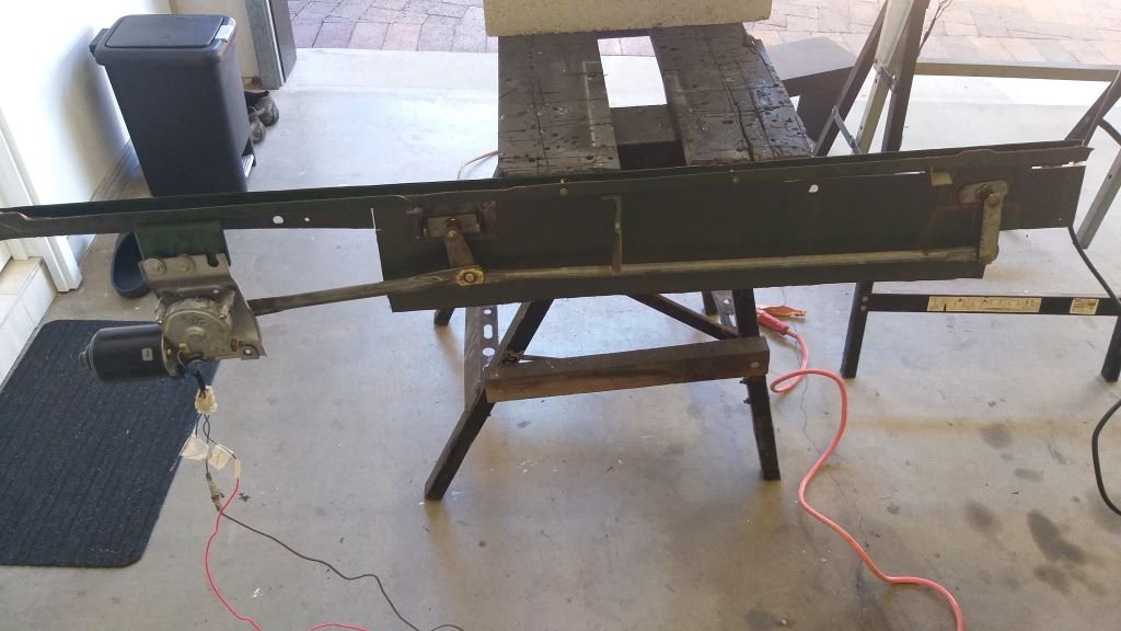
Wipers - Chapter 2 Sandy kindly offered to source a MK3 Capri wiper motor in the UK for me, but as you can imagine they are also starting to get thin on the ground and as a result prices have crept up considerably. I am also worried about finding a replacement in the future should the motor fail, so for now I'm going to attempt to replicate what Sandy has done using a more readily available wiper motor. I currently have two HiAce and one L300 wiper motors that I pulled from my donor vans, so I dusted them off for a quick look and I've set my sights on the L300 one as it is the more compact of the two. I still have the front panel that I cut from the L300 so it was easy enough to setup a little test bed with the L300 wiper motor and mechanism, just so that I could work out the wiring and it also gave me an opportunity to observe exactly how the L300 mechanism works. Reason for this is that the Thames vacuum unit only moves a total of around 170 degrees whilst modern electric wiper motors rotate a full 360 degrees and I needed to get my head around how this is achieved. Anyway, photo of the selected wiper motor below as well as a candid shot of the L300 front panel complete with wiper mechanism attached to my little test bench:
-
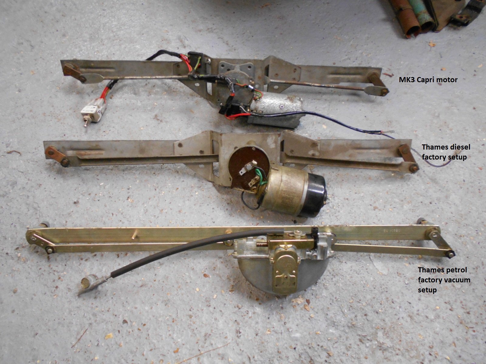
Wipers - Chapter 1 I've been procrastinating over the wiper setup for the Thames for a really long time. As I've previously mentioned the Thames came from factory with a vacuum operated wiper setup. For cert here in Straya the minimum requirement is a two-speed wiper system, so something needed to be done. Earlier this week I was swapping a few yarns with Sandy who up until recently headed up the Thames 400E Owners Club in the UK. Sandy has been restoring and modifying 400Es for over 40 years and is an absolute wealth of information. In passing I happened to mention that I was considering using the early Mini cable driven wiper setup on my van and was advised by Sandy that the wiper sweep angles would be wrong. It turns out that the right-hand wiper on a Thames sweeps around 90 degrees whilst the left-hand wiper sweeps around 120 degrees. This is achieved through the length of the pivot arm on each wiper spindle being different, something that can't easily be adjusted on the Mini setup. So it was at this point that I realised I needed to address the elephant in the room. Now it just so happens that Sandy has done countless wiper conversions over the years. In the early days it was easy enough to source the wiper mechanism out of a diesel powered 400E as these were factory equipped with electrical wipers, but as you can imagine in later years these setups became as common as rocking horse poo, so Sandy started adapting MK3 Capri wiper motors to fit the existing Thames mechanisms. The marked up photo below (kindly provided by Sandy) compares the 3 setups:
-
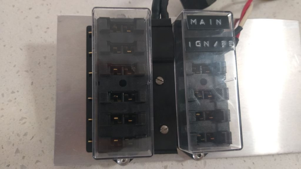
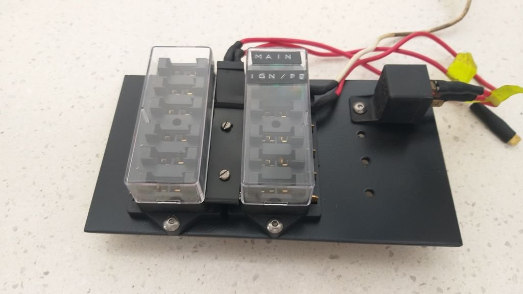
Carved up a little aluminium backing plate for the fuse boxes that bolts over where the voltage regulator used to live. Slapped a bit of satin black on it and made a little cover for the power bus strip out of a piece of black plastic. The relay will feed the ignition powered fuse box with the relay trigger wire being activated by the ignition switch. Doesn't look too bad.
-
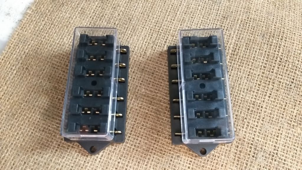
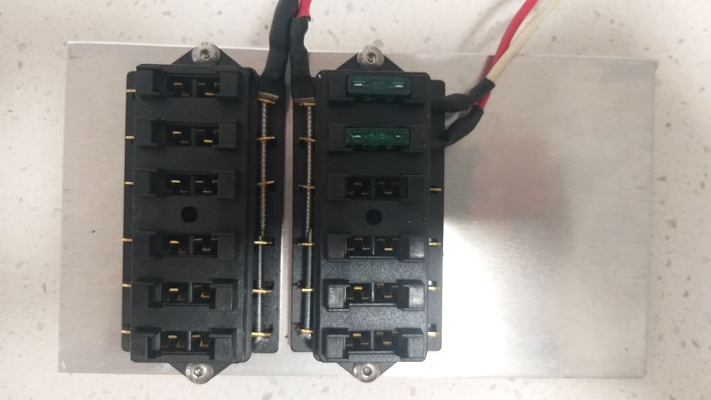
Okay, so back on to the electrical system. There isn't heaps of real estate under the Thames dash, but I decided to fill the little space where I'd previously removed the defunct voltage regulator with a fuse box or two. From factory the Thames comes with only a single inline fuse which is less than ideal if you are planning to add a few modern creature comforts. I have two new slimline 6-way fuse boxes in stock, but I really hate this style as they don't have a common input pole so you end up having to loop the input wire from one fuse to the next. Looks bloody ugly. So after a bit of head scratching, I decided to try an alternative power feed method. Ended up opening up the existing holes in each terminal and threading through a pair of long self-tapping screws that create a common power bus. Looks like so:
-

SR2’s 1947 Vauxhall “Rigamortice” Discussion thread.
Flash replied to sr2's topic in Project Discussion
Sounds good mate ! -
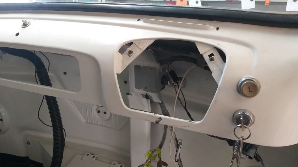
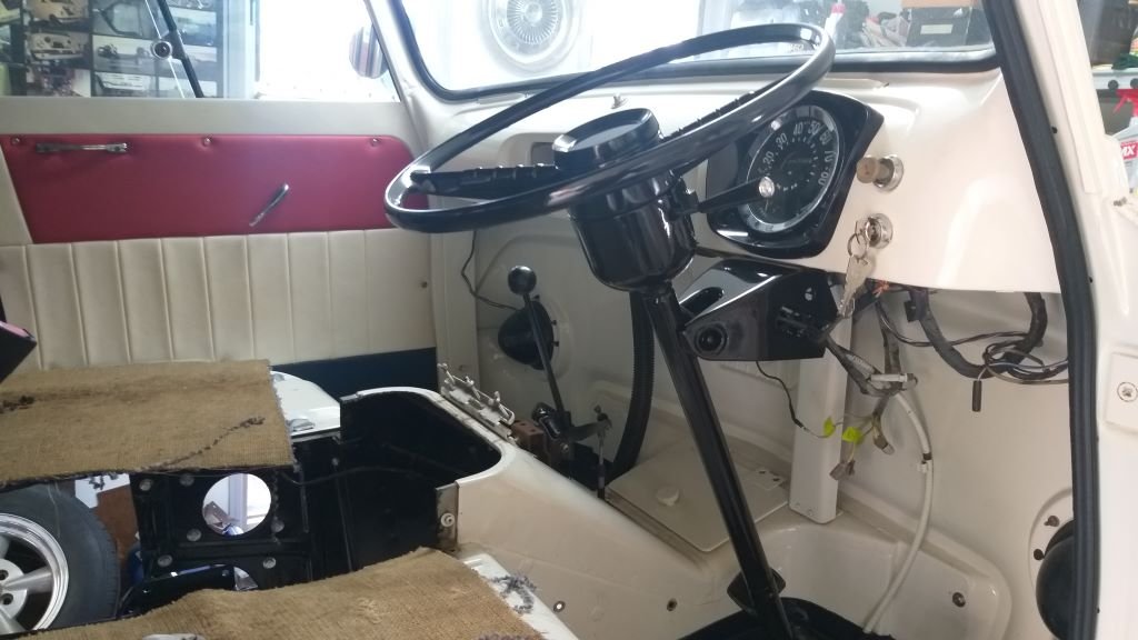
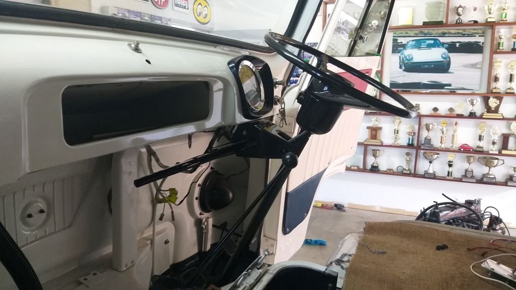
I spent the morning putting in the freshly painted steering column and wheel for the very last time. Fitted my NOS indicator mechanism at the same time so everything is nice and fresh. With the column firmly bolted in place I was finally able to connect up the handbrake mechanism and give it a go for the very first time. Works like an absolute charm which is a relief as it's a real mishmash of Thames and Toyota bits, so I had my doubts about it. Anyhoo, pictures of the fresh install looking rather bling:
- 715 replies
-
- 13
-