


Ja1lb8
-
Posts
242 -
Joined
-
Last visited
-
Days Won
2
Posts posted by Ja1lb8
-
-
Didnt even realize you could get diy kits. Got a bad chip in my screen done at Novus. Bout $50 from memory. The bloke said because it was quite bad it wouldn't be perfect. I'd say it's about a 95% job so I was happy with it. Still going strong a couple years on
-
My auto sr18 bluebird is farken gutless. Should think about servicing the trans me thinks. Gets about 9L/100kms usually 550-600kms a tank. At the sametime inlaws sr20 primera manual goes hard and better fuel economy
-
The one i saw was cut near the yoke so maybe just near the ends were that thick, or maybe it was off something completly different. No idea to be honest. Was pretty trick tho. Looked like the ends were just glued/resined in. Must have been some good shit
-
Have made few drive shafts up and had few different ones made. 1 and 2 piece for different reasons. Talking to the pro/old guy that made shit loads of them for ever. He showed me the graphs for resonent frequency, when the driveshaft gets it wobble on. Took into account length, diameter of tube and wall thickness. As well as it been balanced correctly and the ujoints needing to be aligned properly.
Showed me a carbonfibre dshaft out of a 350z I think? Definatly wasnt carbon for the weight saving. Was heavy as if not heavier then a steel one.wall thickness was about 12mm, used because its much stiffer and the resonant frequeny was much higher. So what I decovered is theres a whole lot of things to take into account when designing a driveshaft but Ive found most times ive just bodged something together its worked anyway
-
 Spotted this while at some Outback Pub along the Nullarbor Western Oz. 37 Chev? Made me sad cos its such a beautiful shape.
Do you know the name of nearest town where this is so I can find it on google maps. Such an awesome looking ute
-
 1
1
-
-
Had this exact problem. Think they were 720cc and was using a microtec which is shit and couldnt get it to idle. Put 370cc back in and was all good.I think it's more to do with difficulty in controlling super small pulsewidths?
As in, your ECU cannot control below 2% opening time. (for example)
That might be fine for 350cc injectors as 2.5% pulsewidth gives you correct idle.
But 560cc might need 1.5%, which your ECU cant do.
Or whatever.
-
Have had several sets of springs modded and made. Snells springs I think did them. Got some retempered so sits more flat. Drilled holes in some also for diff locating dowels which was pretty hard going. The spring guy reconed this fucks ths the surface tension of the spring and increases the risk of it failing but 10 years on still holding strong
-
Had a great day. Good meeting you guys. So many amazing cars there. Particularly enjoyed walking through the workshops out back and seeing all the yet to be restored cars they had stashed away
-
Could be keen to bring my old datsun super six down. Be good to meet some if you guys. Have to see what works doing
-
2
-
-
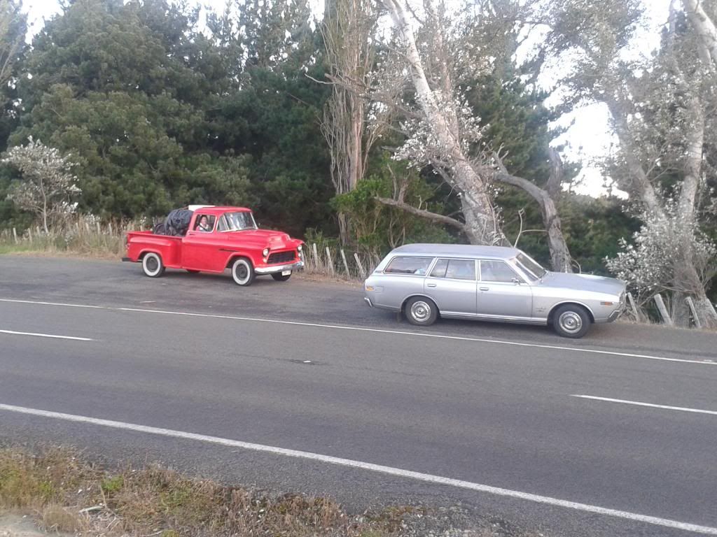
Saw a super sweet 260c wagon today heading toward Taupo from Rotorua.
Looked mint.
Which of you creeps was it?
Was Silver with whitewalls.
Otherwise stock as a rock!
Guilty... on a roady back from east coast to the naki]
-
Exactly what all torque said and yea I would think about .1mm would be the go. The replacement ball joint does have a grippy spline thing rolled into the contact face of it. Wonder if thats meant to sort of cut in as you press it in?
-
Assembling my new suspension arms and just checked the interferance between the balljoint and the hole it has to go into , .97mm, Seems excessive to me
I can just put it in a big press and itll stretch the outer ring thing and go in most probably but im a but scared it could split it also damaging the arm.
Anybody know how much interferance is standard on a ball joint , think lower hq holden or similar
-
- Popular Post
Front suspension MK3
Brought a nz hobby car manual that says what you can and cant do in regards to building a car in nz, should hve got one when I started this but im not usually one to do things the easy way,
So found the suspension arms I made wearnt up to spec, need to to be beefier and need to tig'd, not mig welded plus i didnt like the rod ends so heres the new ones with bushed rod , hopefully should be a bit nicer ride then the solid ones and not wear out like they tend to.
Threading the ends for the rod ends, 3/4únf
Made up some press tools to put the ball joints in and tryed using my bench vice but no chance so shot down to the local engineers and he let me use his big press
Final welding on bottom A arms, still need to make a mount and hole for the shock mount to and somewhere for a bump stop
Waiting on bushes and more rod ends to show up so I finish mount these ,
-
16
-
Have managed to get a bit done on this lately, feels like im going round in circles a but tho cause most of it involved cutting bits off I wasnt happy with and redoing them
Anyways...
Cut back of chassis off cause it looked shithouse and made up new chassis rails, also means I can get a decent sized fuel tank in there
Have mounted rear shocks and got all that working, still need to make up new rear arms but have most the bits I need now
-
1
-
-
Heres my old beater, ticks all the oldschool boxes, exposed gears, exposed belts and exposed chains, Surprisingly its pretty accurate, spent ages lining up the head and tail stock properly so it doesnt turn a taper, had to shim under the headstock to get the heights right. Its about 1.2m between centres and can get a 15" rim in it with the gap taken out of the bed
Used to be belt driven way back when but some clever buggers adapted a really old 3 speed car gearbox to it, think 1930s?
Looks like its had a bit of a hard time at some stage, check out all the braizing around the main spindle bearing and the gear thats been welded back together
-
6
-
-
Got a good days work in on my chassis today so heaps of little bits and pieces finished. Probably another solid days work and itl be ready to go to the sand blasters and get some paint on it
A while back someone commented that it looked real heavy with all that bracing in it, Since I had some load cells laying around and the readout was charged up (used for wieghing cows) I thought id chuck them under my chassis just out of interest, came in at 140kgs which I didnt think was to badat all. Will get maybe another 10kgs of bits and pieces welded to by the time its finished
I almost epect the weight to double by the time i add the suspension, brakes and wheels tho
-
3
-
-
In hindsight I should of just whacked a couple of singles on there and not had to battle with this plumbing nightmare but Im already balls deep so I best see it through now
-
Have spent the last couple of weeks working on the exhaust and finishing off bits on the chassis
Removed the body shell and set to work on the drivers side exhaust , Had to get it to clear the steering shafts and fit in between the chassis rails, Just waiting on some v band clamps to show up so I can finish weld it, otherwise all looks good
Next I moved onto the passengers side , had to modify the manifold so it faced the other way, easier said then done but its in there now, 3rd time lucky and appears to clear everything, Hoping the motor doesnt rock to much and make the exhaust hit the chassis
Like the other side im going to have to put heat shields around everything to try and stop things melting, starter engine mount etc
-
1
-
-
Yea man, worked a treat
-
So been fitting the rest of the steering shafts and universals
First problem I struck was needing a spline on the input shaft of the rack and pinion
Thought about it for a while and ended up making up a dividing plate out of an old torana disk brake and welding it to the spindle of my lathe, worked out way better then I thought it would and actually cut a pretty decent spline
Then had a few goes at different mounting positions for the support bearing , main problem being clearance around the exhaust
Its about as good as I can get it now but well have run heat sheilds around the centre ujoint and hope it doesnt boil all the grease out of it and wreck it
Well finish up all the bracing for the support bearing when the body comes off and engine out next
-
2
-
-
Package arrived today with steering components in it so thought I best mount the column and fingers crossed itl all work
The U joints and shaft appear to be pretty good quality but the rod ends pretty shit and well probably end up getting another one
Got this tilt column for cheap off trademe, was told its out of some old chev , Im thinking late 60s early 70s but not really sure
Made the top mount and will pretty it up a bit by making some sort of cover that merges into the bottom of the gauge cluster
Next Im going to mount the bottom of the column and cut a hole in the firewall, hope i measured it all up properly and itl clear all the turbo piping and exhaust
Note crappy steering wheel is just so I could mock it up and make sure I was happy with where it sat
-
Have fitted the gauge cluster, still need to weld in some mounting tabs for the screws and fill in around the bottom of the v part of the chrome, going to incorporate it into the steering column mount somehow
Not sure what to do with rest of the dash tho, might just fill in all the holes although some of that old chrome stuff that came on it does look pretty cool
-
just cause you got me worried I thought I best actually put a 17 on a see what it looks like instead of just measuring it and hoping for the best
should be all good
-
1
-
-
Thanks Thomas , You have any luck with those tarpolins?


Importing a V12 Toyota Century
in General Car Chat
Posted
Did you end up getting one of these? I have all the panels and lots of other interior parts available if you require any of them?