
Leaderboard


Popular Content
Showing content with the highest reputation on 08/08/22 in all areas
-
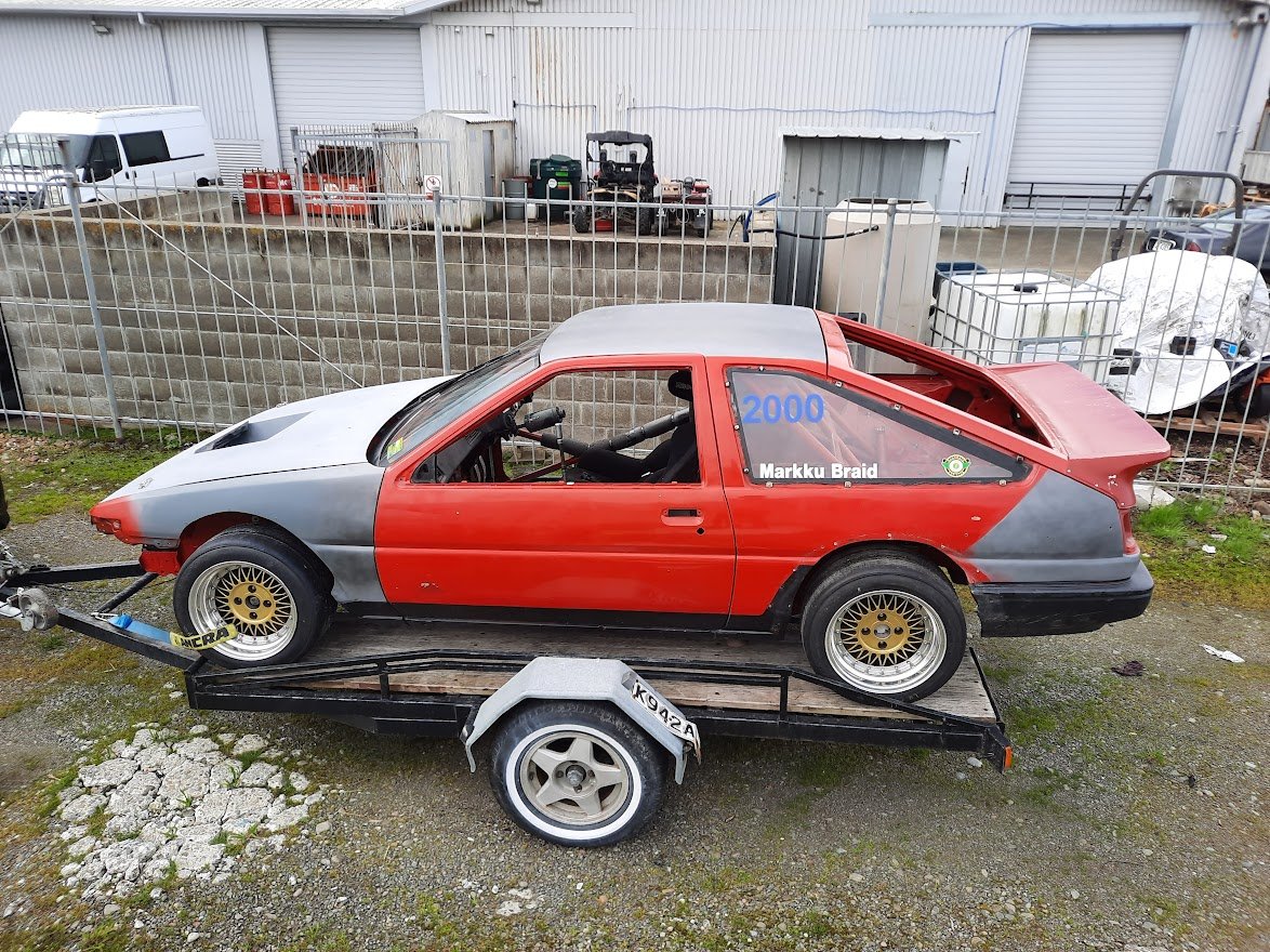
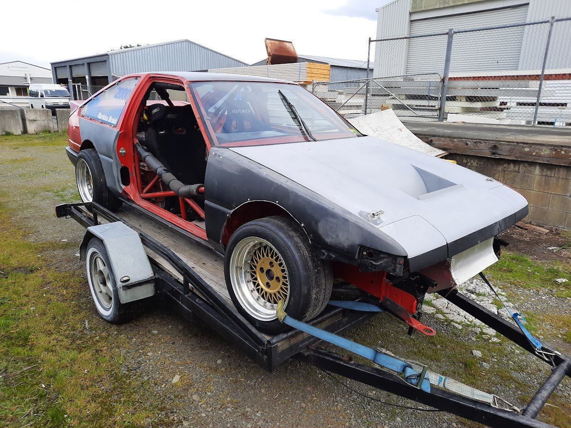
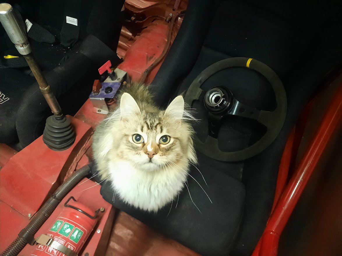
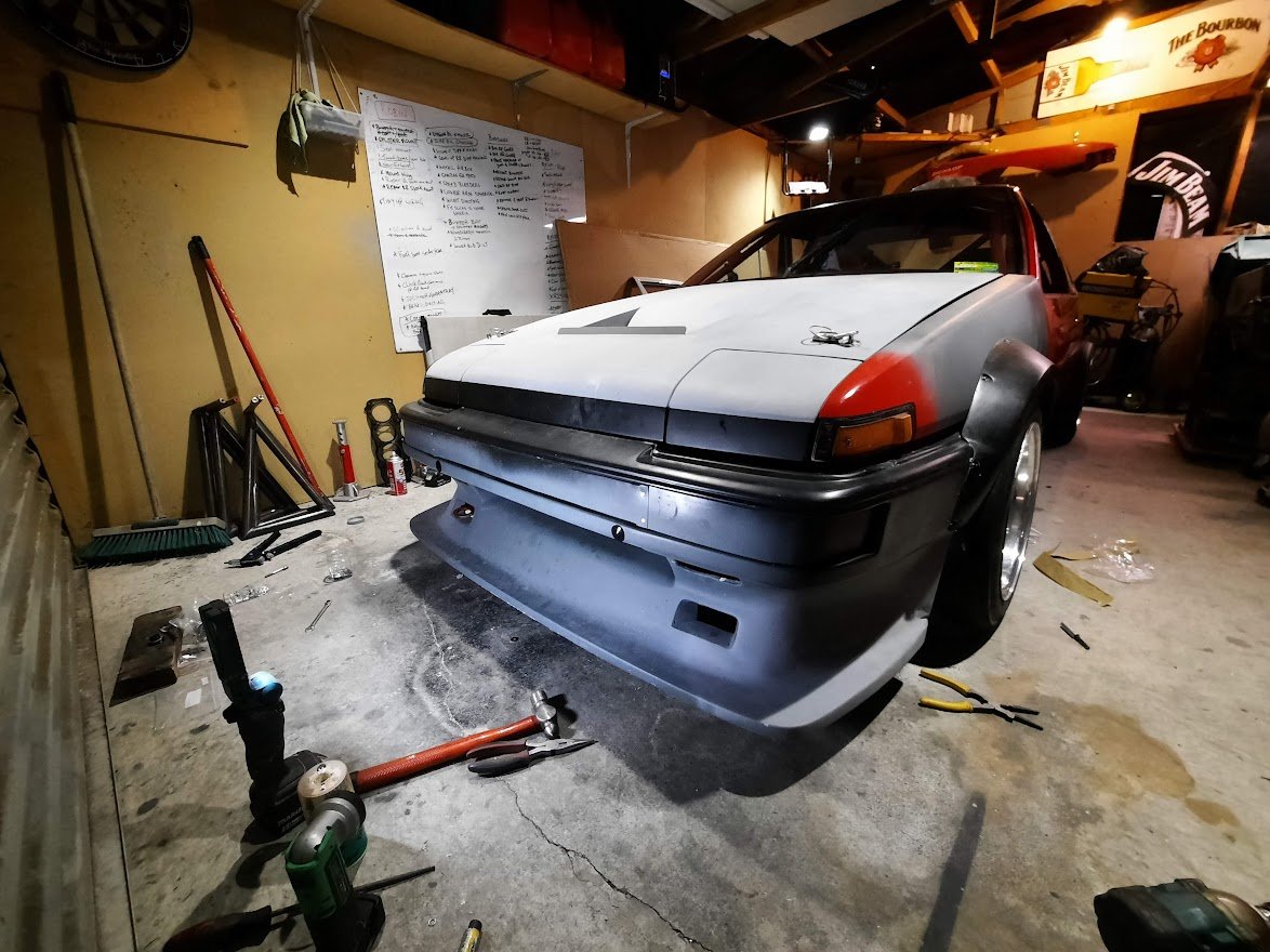
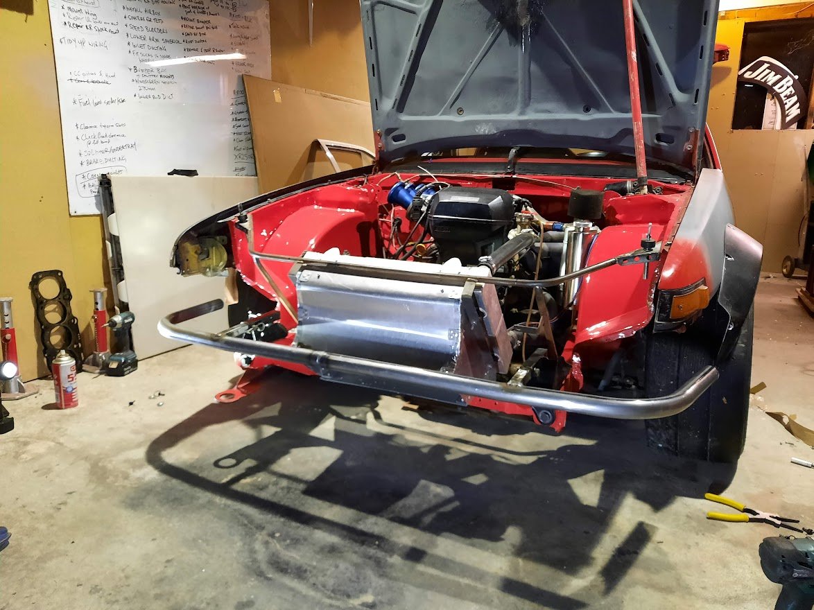
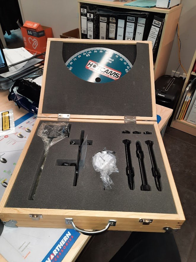
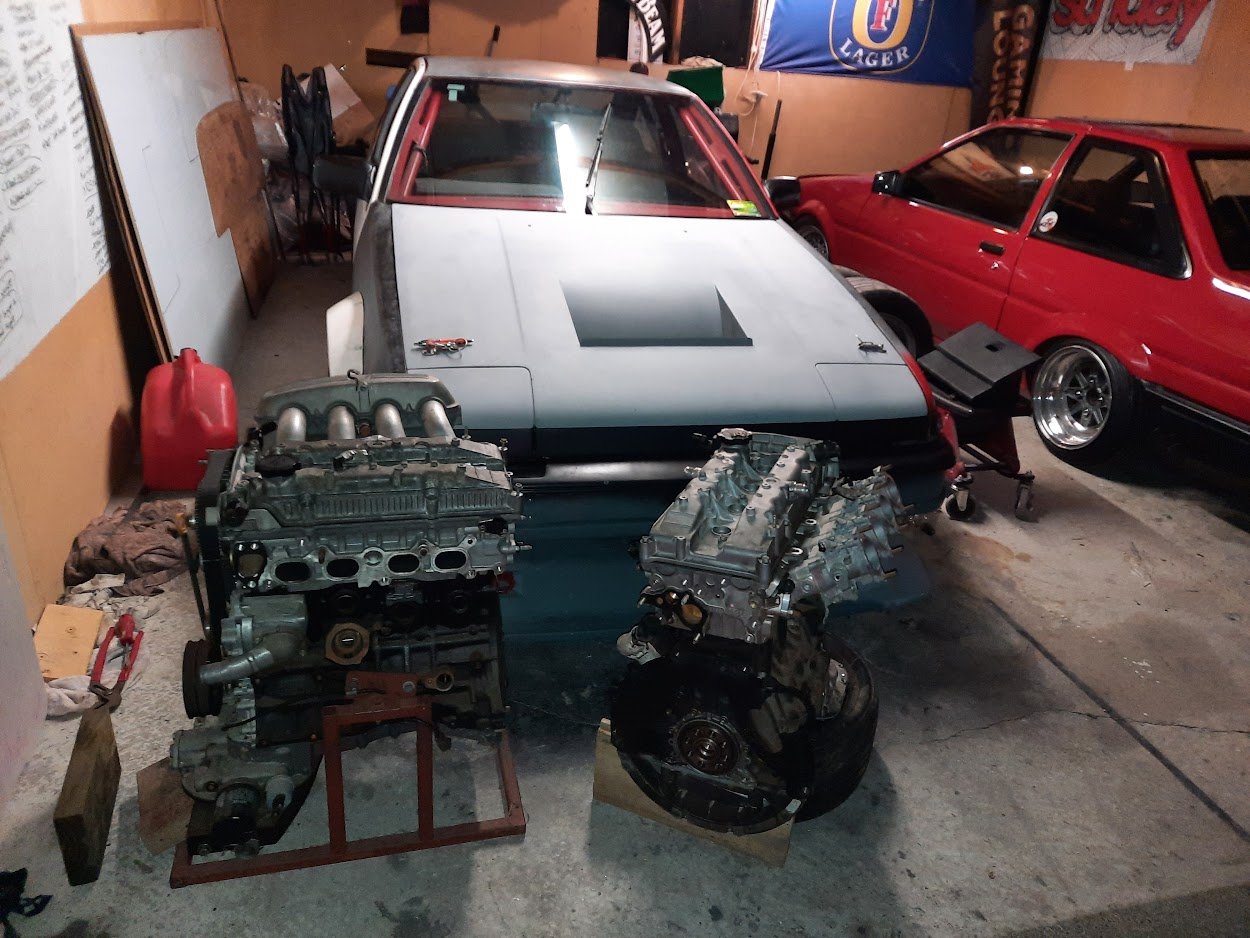
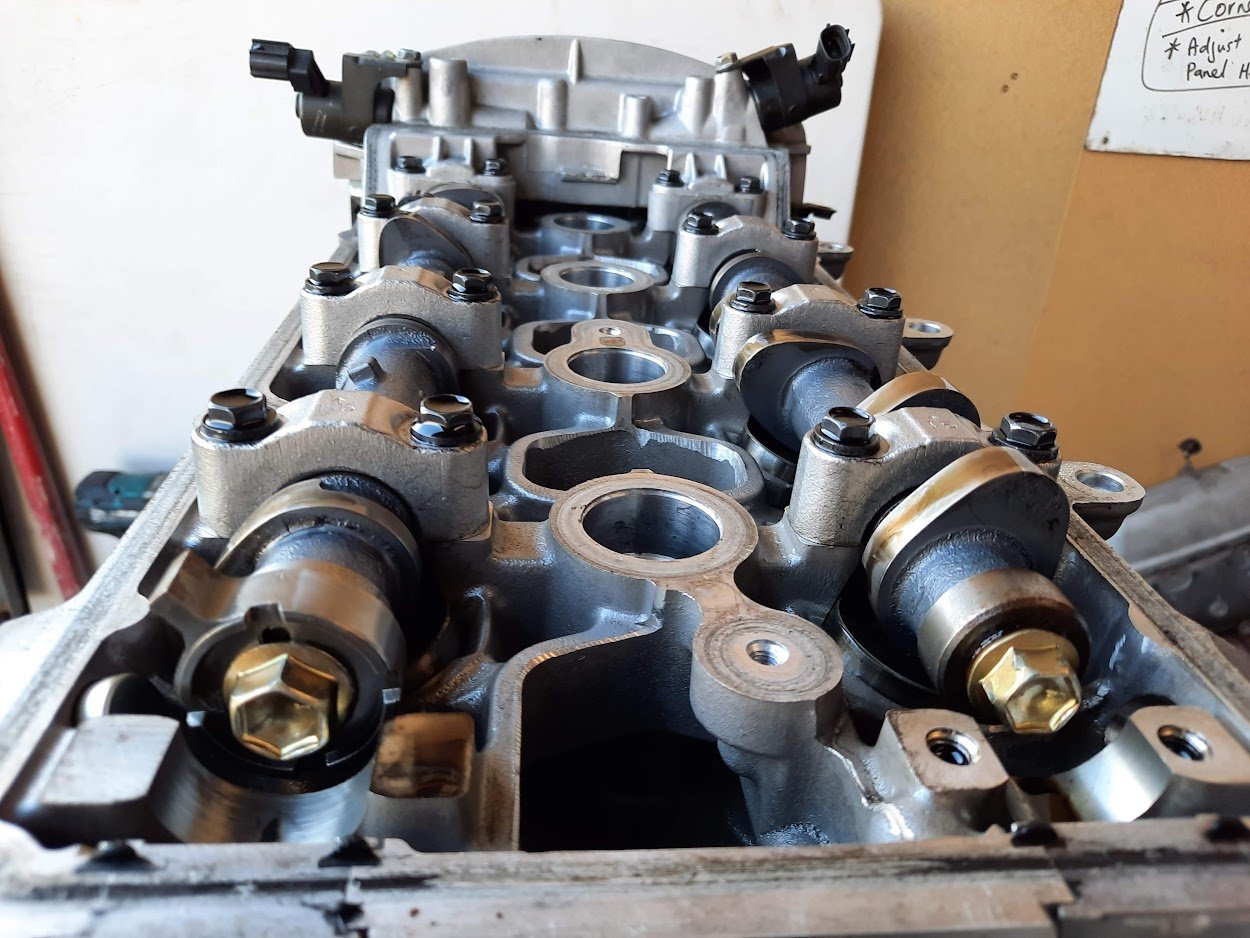
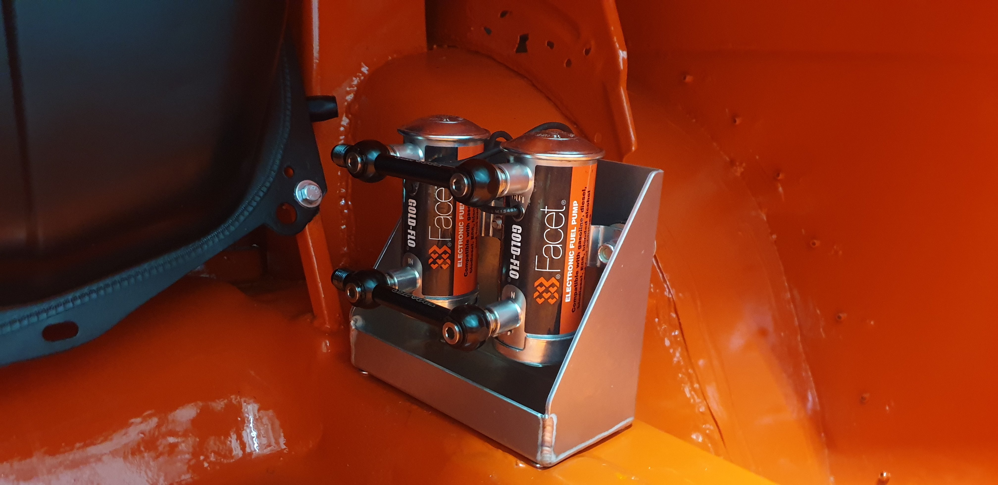
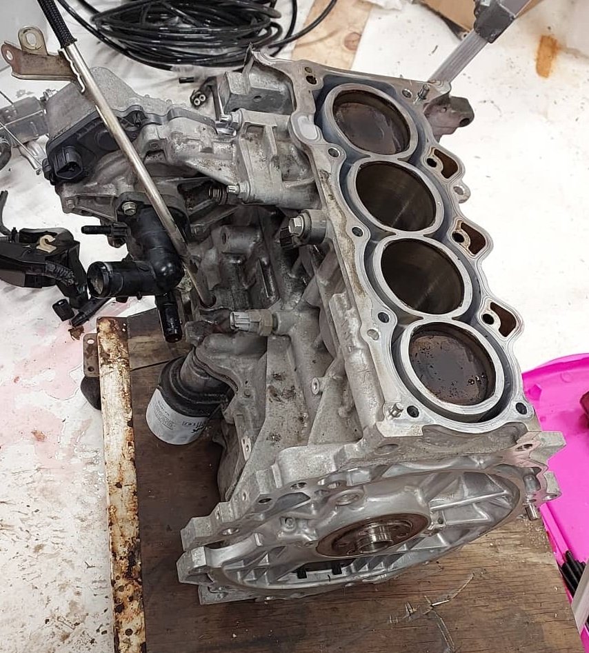
One job I've been wanting to do for a long time is update the bumper mount to make it quicker and easier to fit. It needs to be removed every time it goes on the trailer, so my requirements were that it needed to be strong and tool-less to install. Nick at SAFEngineering bent up a bar out of offcuts for me and I've used quick latches to attach the bumper to the bar. The flares connect with little 1/4 turn motorbike fairing fasteners. I've also picked up a couple of modified engines to get my engine upgrades moving. One is from a TRD NZ Altezza touring car that ran in the NZ Touring Car series in 2001/2. They had limitations on cam lift and compression, so it's not an all out race build, but should work nicely for what I want to do and still allow full use of VVTi. The cams definitely have some lump to them: I bought a cam setup kit to measure everything up and be able to re-set the timing if the VVTi can't be used for some reason. This allowed us to work out the cam specs, which is around 264º at .050" and 313º at .010" (advertised duration). @CXGPWR is helping me out with the engine project. Thanks John! Now it's off to the panel beaters for a final bit of bodywork and some fresh red . I'm looking forward to seeing it in colour again! And I'm sure Taco's keen to spread his fur all over the seats when it gets back.
 20 points
 -
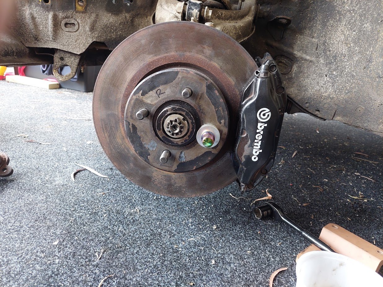
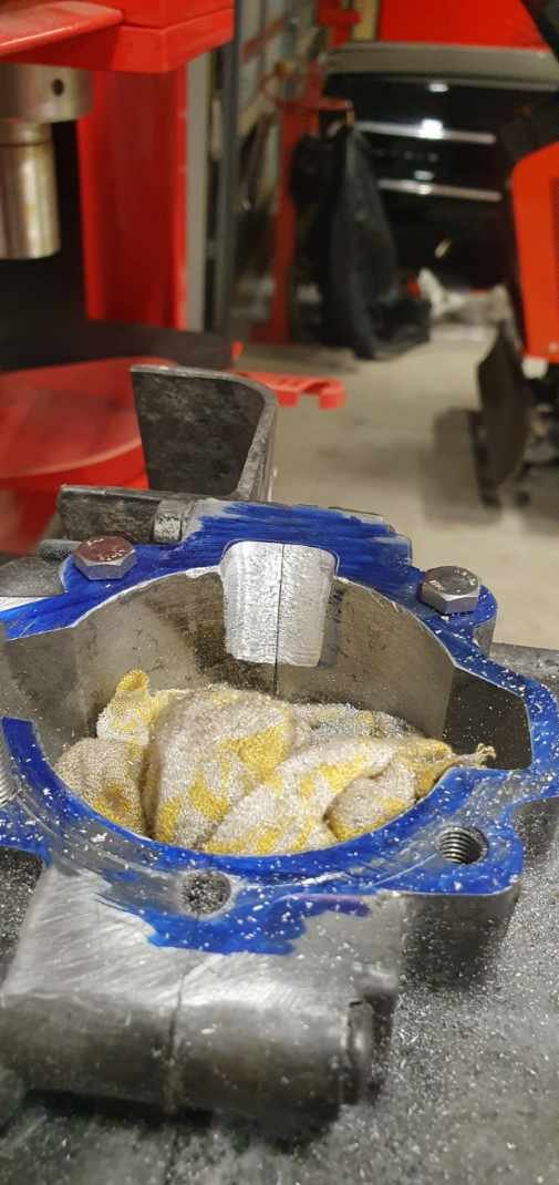
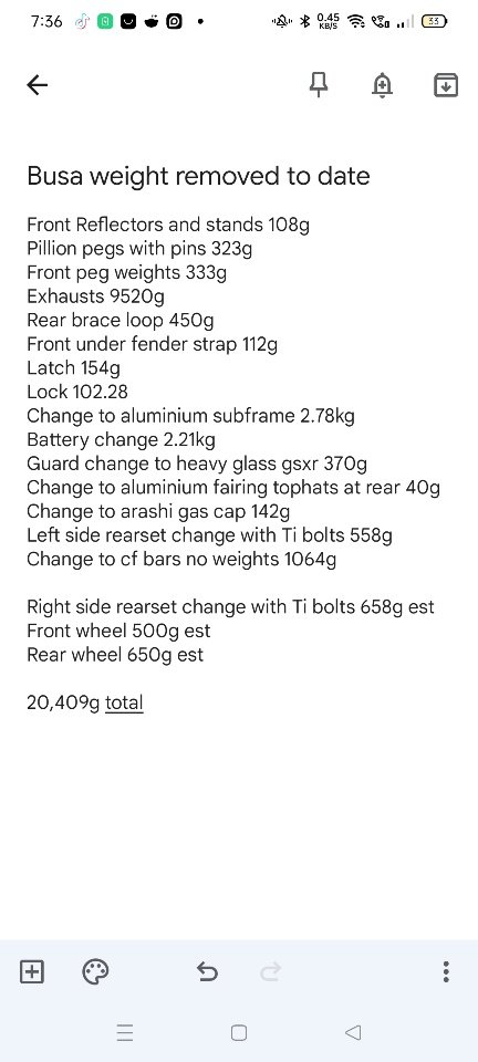
I've been putting off touching the rear hubs because they've been unkind to me. The axle nut is torqued down to stupid foot-libs and I was really struggling to get it off. Max send on impact wrench, the pair of us with crowbar and breaker bar in various strange configurations and our full body weights, I even drilled four holes into the bench to slot the hub into which wasn't useful. For some reason I waited till the end to try the vise, but when I did it worked second try. Even then I had to find the right angle as the breaker bar threatened to tear the bench down (and I don't trust the person that engineered it). Then I put my little gear puller into use once again, followed up by a rubber mallet at full send when it reached its max travel (manual says "tap it out", yeah right). There's what I now know is a "blind" bearing that has no purchase on any side of it. The manual says to use a blind bearing puller, which involves using a special tool to punch into the bearings then each lever in the puller is inserted then turned 90 degrees to pull against the outer and inner races simultaneously. It costs $1500. So I instead went to the internet for advice. Someone managed by removing the bearing retainer then smooshing all balls against one side to be able to knock the outer race free, then cut the inner race off. They also said "good luck" if that retainer was metal and not the more modern plastic style. Feck. But it was a good start so I somewhat carefully just took to the bearing with a variety of chisels, punches, drill bits and screwdrivers in an attempt to mangle the race free. In hindsight I had no chance of succeeding but no harm done. What worked: I took a dremel to the outer race. The geometry didn't let me cut all the way through it but some more "experimentation" with a chisel revealed that the remainder of the race split very easily with a few taps! I dremel'd the other side, and a single tap opened it up. The retainer and balls then slid/fell right out. Again the dremel geometry wasn't favourable to completely cutting the inner race but I was hopeful. I cut as much as I could without risking cutting into the permanent bits. This time instead of splitting entirely, the cut made a perfect purchase point for the chisel to work the inner race free such that I could just slide it off by hand. Yay! What was hours of faff turned into minutes for the second hub now that I knew what I was doing. Then I clawed all the grease out of the hubs like Pooh with a honey pot and gave it all a solid parts wash, ready to mask up once it dries. Phew!10 points
-
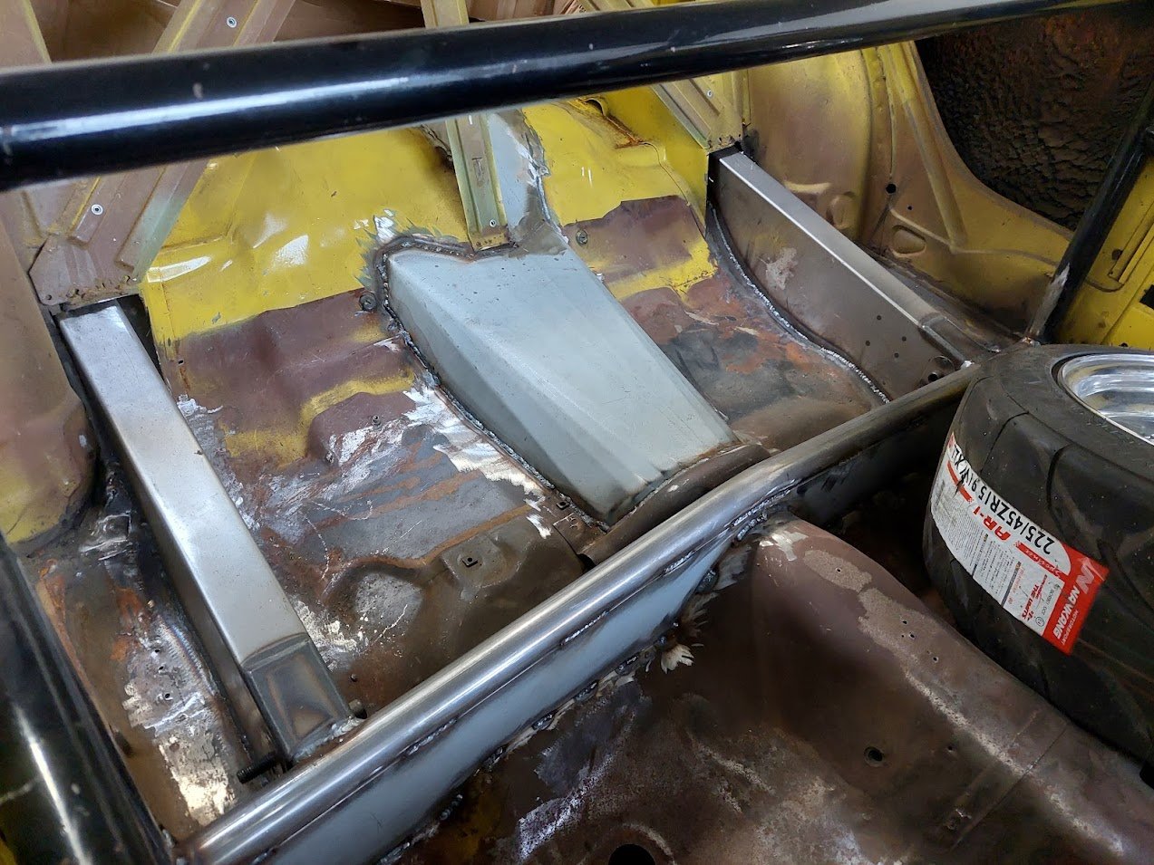
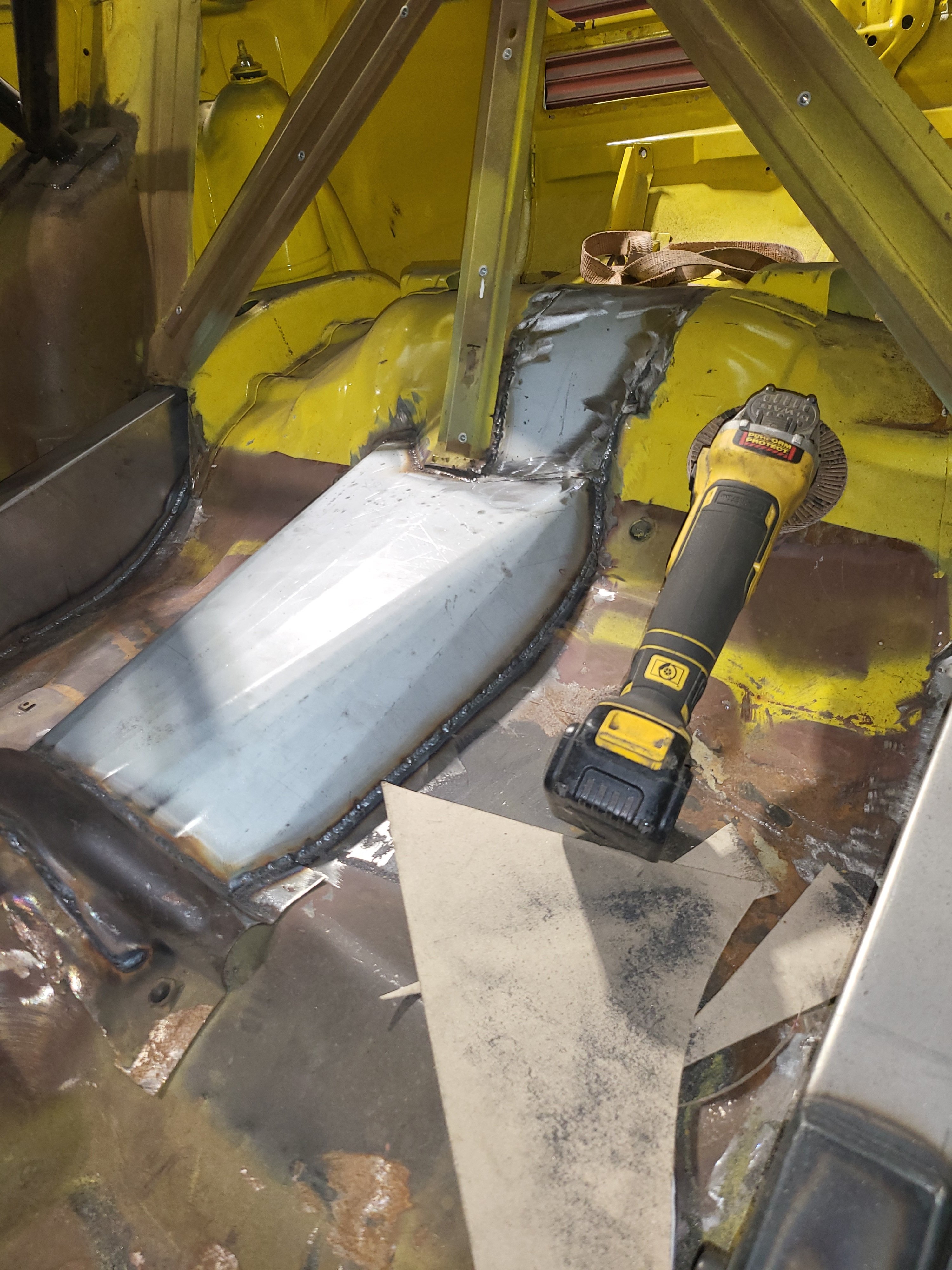
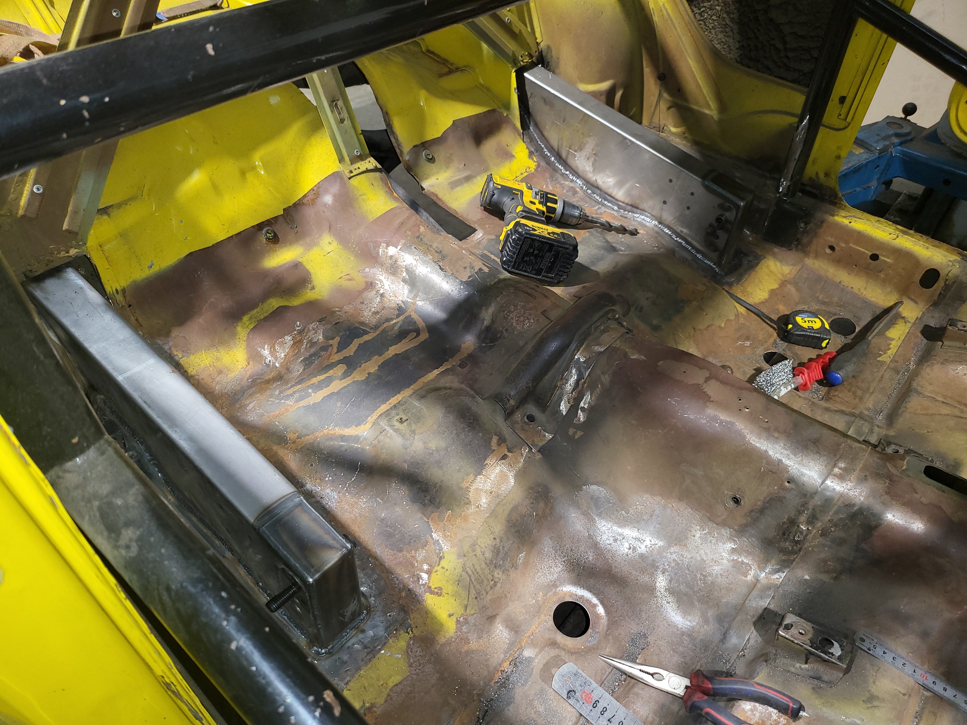
The car is back home now. The brackets and tunnel are done. Next bit to do is buy some coilovers for the rear and mount them up nice and neat. I've decided to swap the upper rear mounts from single stud to and eye, for ease of buying the coilovers as well as strength.
10 points
-
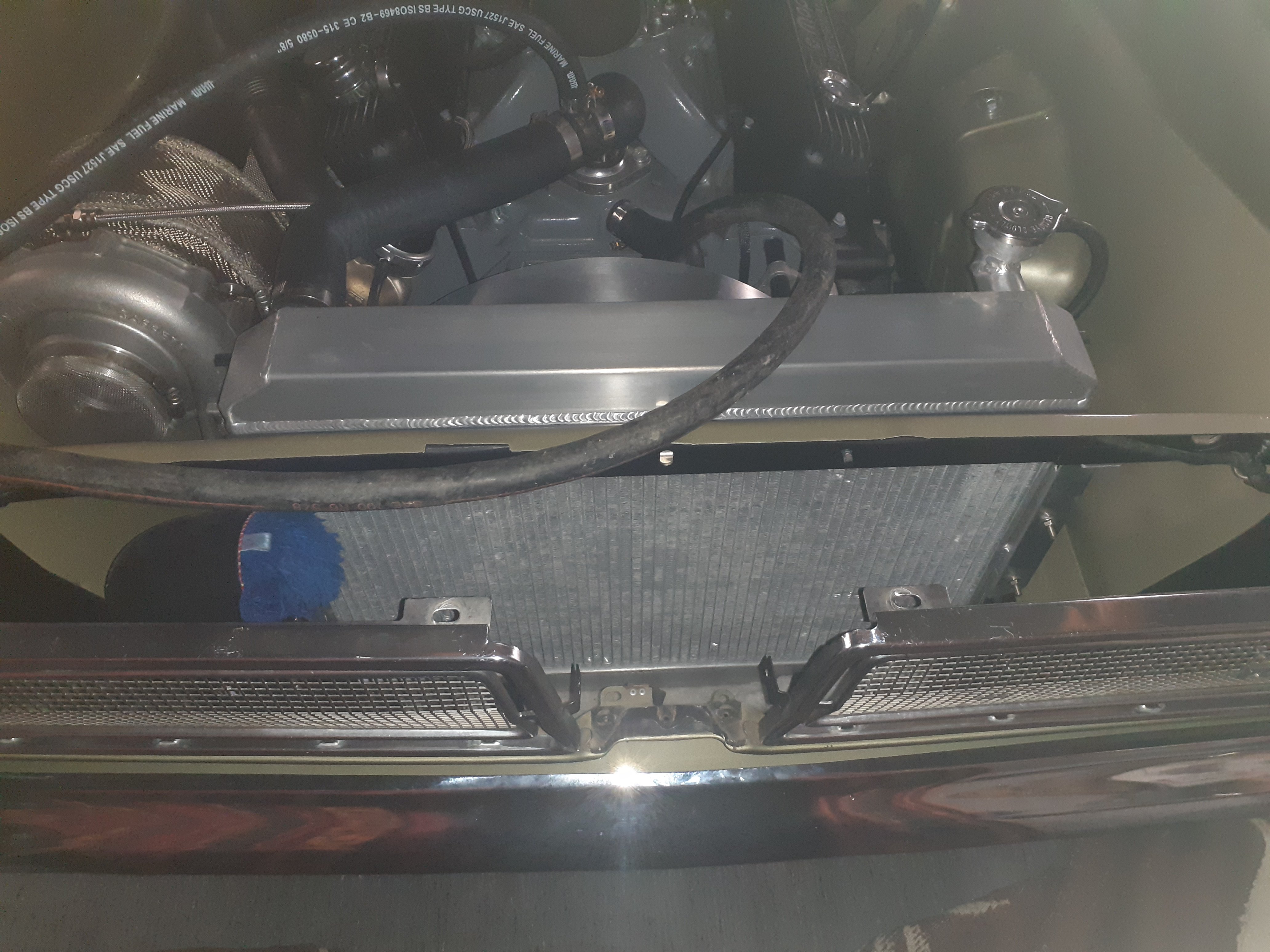
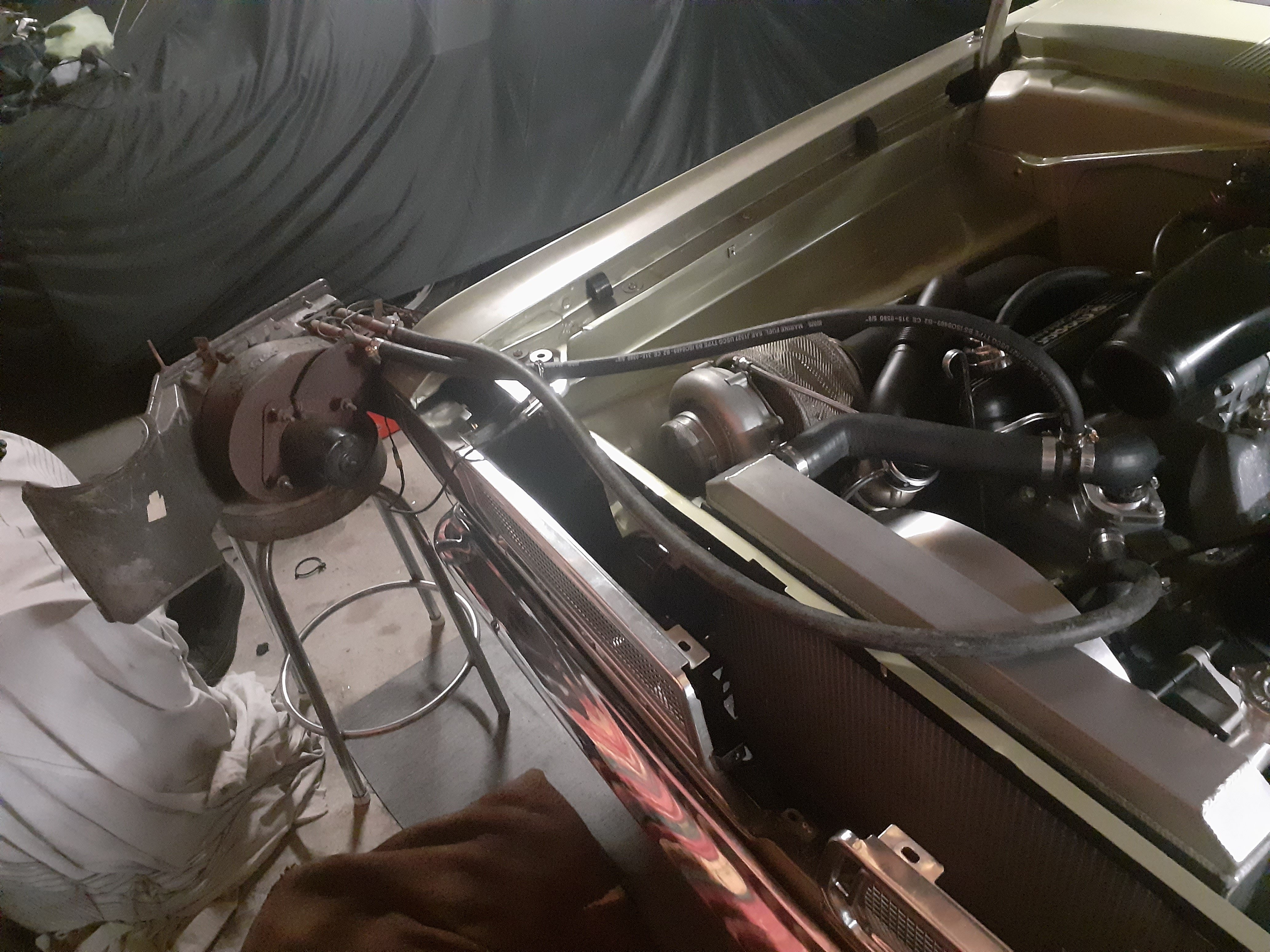
Can also add to the list of "probably slowed the overheating but did not stop it" Heater core auxiliary cooler, this showed an 18degree difference in hose temps between hot and cold side Removal of intercooler. Side note at idle there is a warm breeze of 54 degrees coming out of the turbo
7 points
-
I've heard that the auto starion has a different diff ratio to normal so while I had it open I measured it - 3.909. I also dragged the old one out and got it open, but it's also 3.909. I dunno, maybe the new LSD is from an auto too... but I'm glad I don't have to think too hard about what effects the swap will have! As there are negative quantities of new gaskets for starions out there, and the interwebs seems fine with just gasket maker for this application, I decided to go that route. Break cleaner'd all the gasket surfaces and waited to dry. Applied a smooth continuous bead of permatex ultra black that would make any professional cry with joy (or just cry). Gently lower onto the diff and hand tighten a bunch of crappily passivated bolts (I'll post about my electroplating efforts later... still nailing it down!). After an hour, twerked down in a chris fix pattern. I also schmoo'd a bead around the breather and attached it. The breather used to have a little ring that is meant to be lubed up and pushed through to hold it from the other side, but that tore off in moments... so it's just the gasket maker holding it in right now. I've given it a few solid tugs and it seems okay but I can try again with the old diff's breather if I have to in the future. And hey while I'm here... greased up the splines on the torque tube and its bolts and connected it all up. I also torqued up the drain bolt because I know I'd forget. There's not enough purchase on the diff right now to be able to torque it down easily so I just left future Tom a note. That's one more complete thing I can store and ignore!6 points
-
Brakes are on!!!!! hoses and lines connected. have ordered some pads from palmside for “fast road car/high performance “. once they arrive I can fit them and bleed it all up. Check for leaks, apply electrical tape and cable ties, walk away. also altered the gear stick angle for a more rearward position. Easier to reach 1st now. post cert I will get new carpets fitted. next on the list to do: shifter hole cover and boot, adjust rear brake shoes, bolt check. Wait for engine to be built. Add in the extra resonator I have. Modify the centre console for the new shifter hole shitchea!!!
5 points
-
Okay.. last post about these rear sets. Finally all installed with torqued and loctited Ti hardware (cheaper to buy it in silver and just dip them yourself and it's only a few seconds, plus the color matches) The left side with Ti hoop was a BASTARD to color because the act of heating the Ti to do the riveting creates a layer of oxide that must first be removed. It's a patchy gold/red/purple now which doesn't match the other side, but for now it will do. (Occured to me this morning that I might need to visit @Kimjon for a Hoon on his sand blaster then immediately anodise to fix the problem) Extremely happy with how it's all come out ☺️.
5 points
-
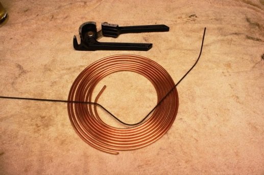
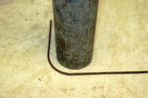
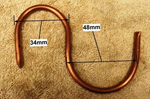
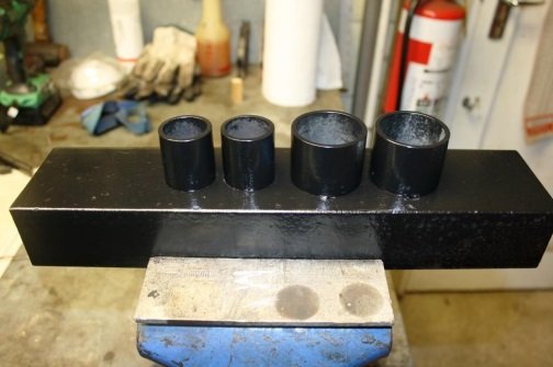
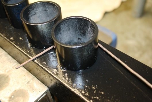
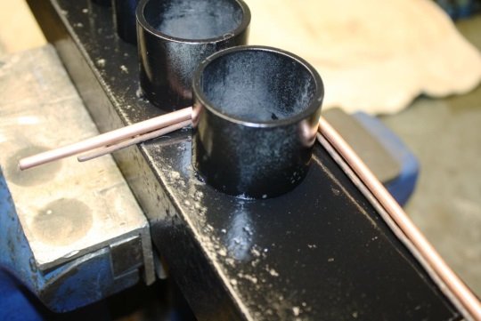
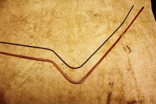
Brake line bending 101 Hi guys; more semi-incoherent, sanctimonious musings from the Universally Renowned sr2 man-cave University of Beer, Bullshit and Bad Manners. As always feel free to comment, disagree or just sling random insults. https://oldschool.co.nz/index.php?/topic/49843-sr2%E2%80%99s-1947-vauxhall-%E2%80%9Crigamortice%E2%80%9D-discussion-thread/ Just finished a brake & booster upgrade on a friends MBG GT and thought I’d share my brake pipe fabrication technique. For what it’s worth this is how I do it. In the late 70’s and early 80’s copper tube was commonly used and we produced some very pretty hand bent installs. In its defence despite copper being soft and susceptible to work hardening we had no failures due to the material used. These days with higher pressure/less displacement systems copper is frowned upon and after a brief flirtation with steel Bundy tubing (bloody awful stuff) most of the industry has settled on copper nickel tubing. It’s malleable, looks the part and is a joy to work with. Traditionally I’d make a pattern using 2.5 mm welding wire and then attempted to replicate it with my trusty bender. Problem was replicating handmade wire bends with a set radius bender at best produced an average result. After a rare Wild Turkey inspired flash of inspiration (i.e. a rush of shit to the brains) I tried using a piece of scrap pipe of the correct diameter (i.e. 48mm as per my tube bender) to bend the wire pattern. Things got a lot easier but it was still challenging to get the length of tube between the bends consistent with the pattern. I had a little play and discovered that with copper nickel I could ditch the bender and just wrap the tubing around my pipe former and better than that I could even manage a smaller 34 mm radius bend without distorting or collapsing the tube. Next step was to knock up a 34/48 mm bending former out of scrap. I use the bending former to bend the wire pattern… And then line the tube up to make the same bend in the same position. Easy as… Bottom line is if you use the same bending former for both the wire pattern and the brake tube you save yourself a lot of grief.
5 points
-
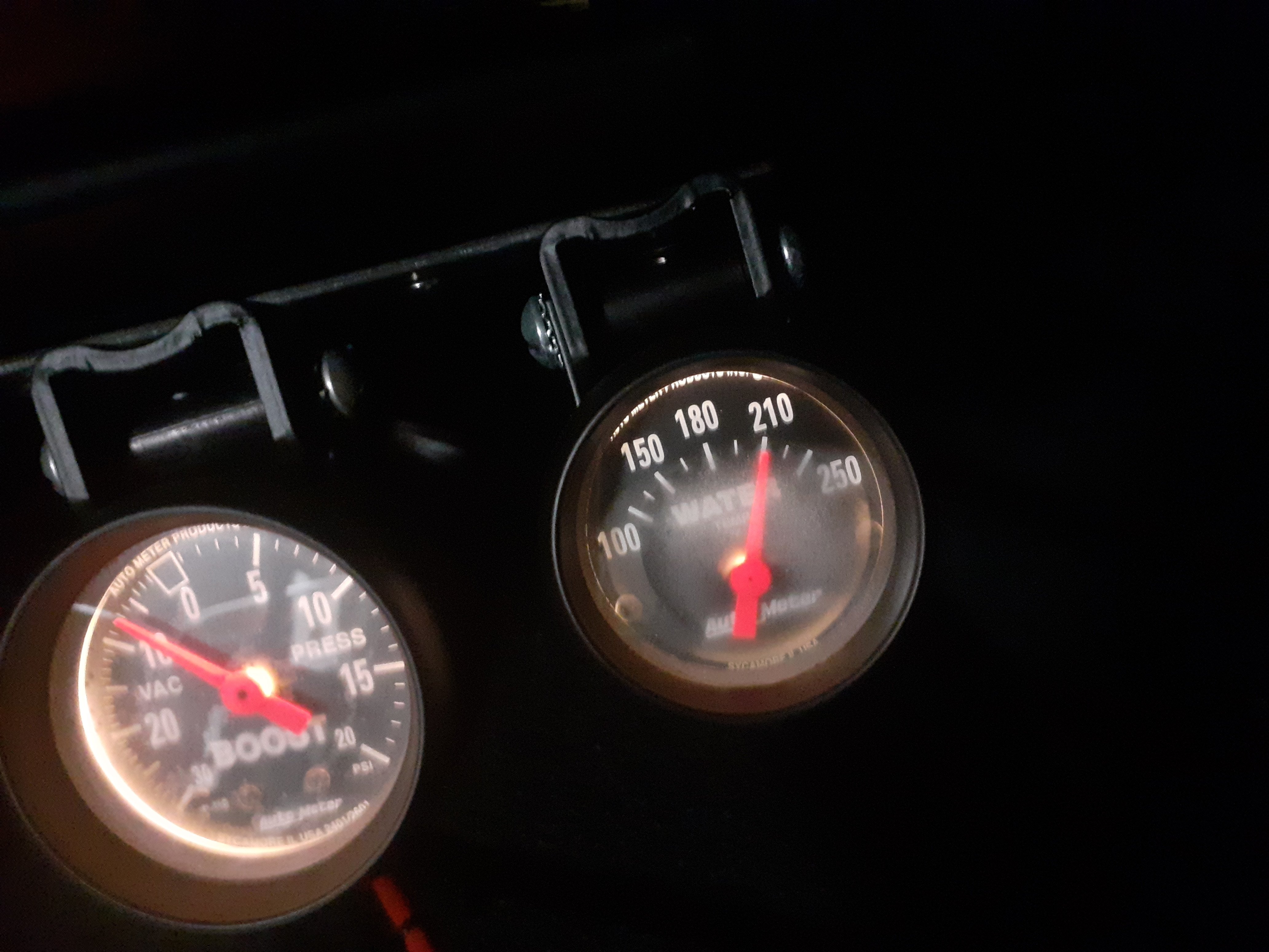
My new water pump controller arrived Saturday, props to Davies Craig for sorting it quickly. I plugged it in and everything looked good. I gave it a test today and ran it for about 30 mins. Temp limit was set to 85 degrees so when it hit 88 the fan came on and within 30 seconds the temp had come down to 85 again, pretty happy with that. I let it do this a few times and it seems to be working well. Only issue remaining is the time it takes to warmup, I suspect they'll recommend a thermostat with some extra bleed holes in it but I'll run it past the manufacturer and see what they recommend.5 points
-
New shiity bike acquired for this year. Also keen to jump in on accommodation if any going or someone hasn't booked
4 points
-
9New direction, I was taking the fog lights off when I remembered I had a box of lights that might work. So now I have DRL's instead, dekatora running lamps. I have some spare if anyone is keen.3 points
-
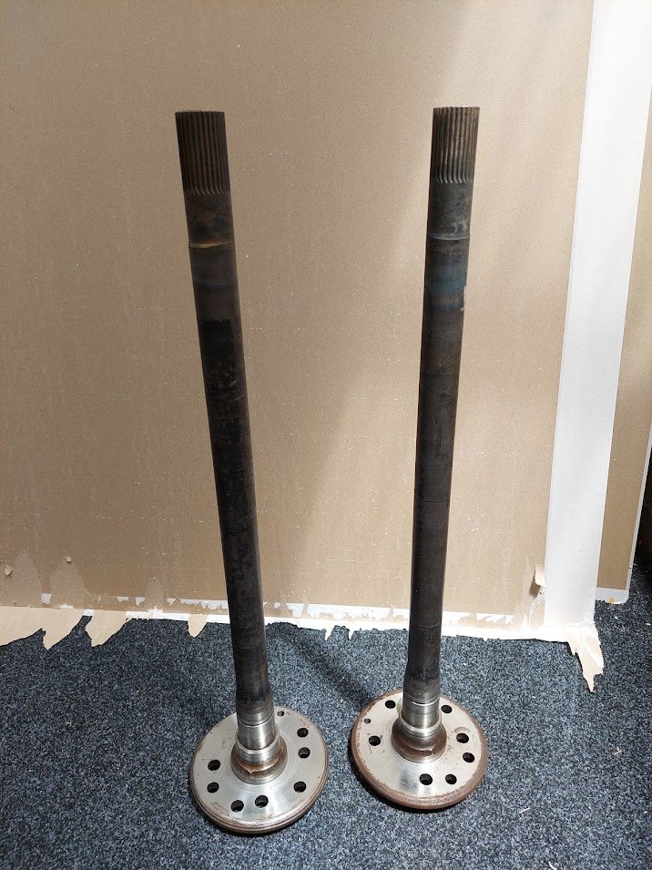
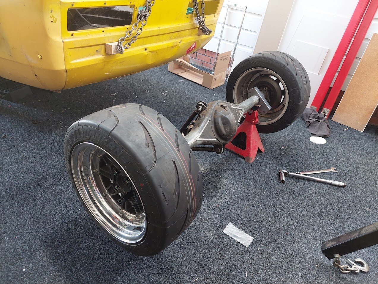
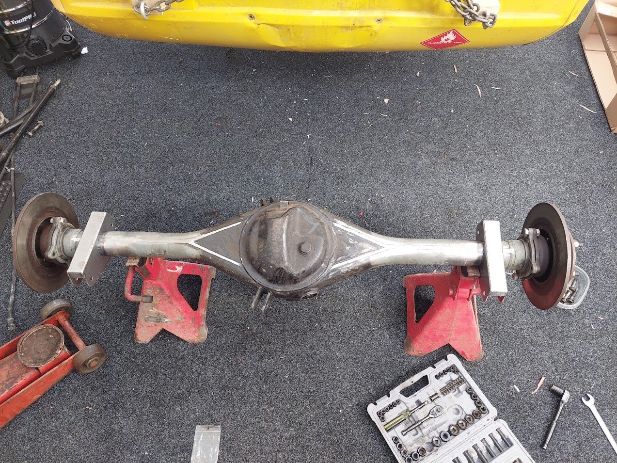
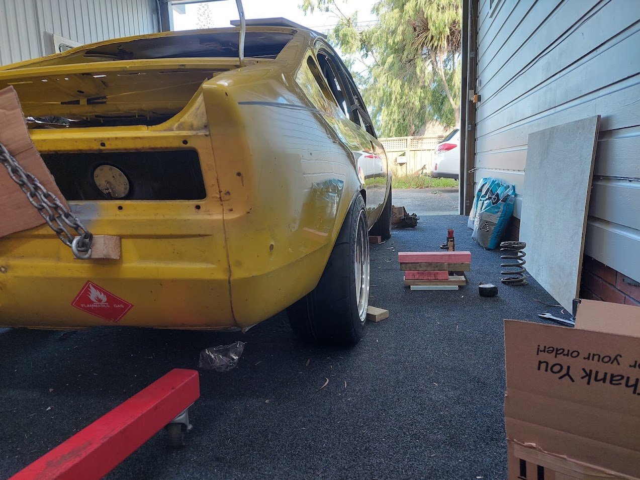
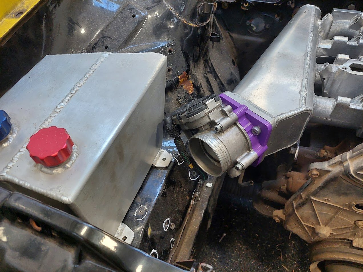
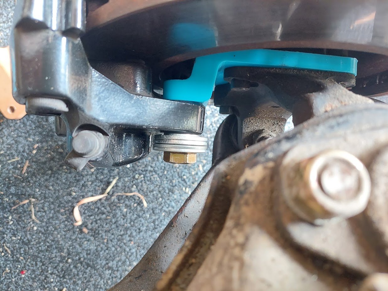
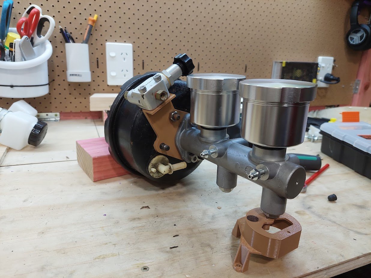
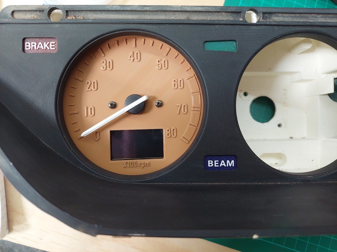
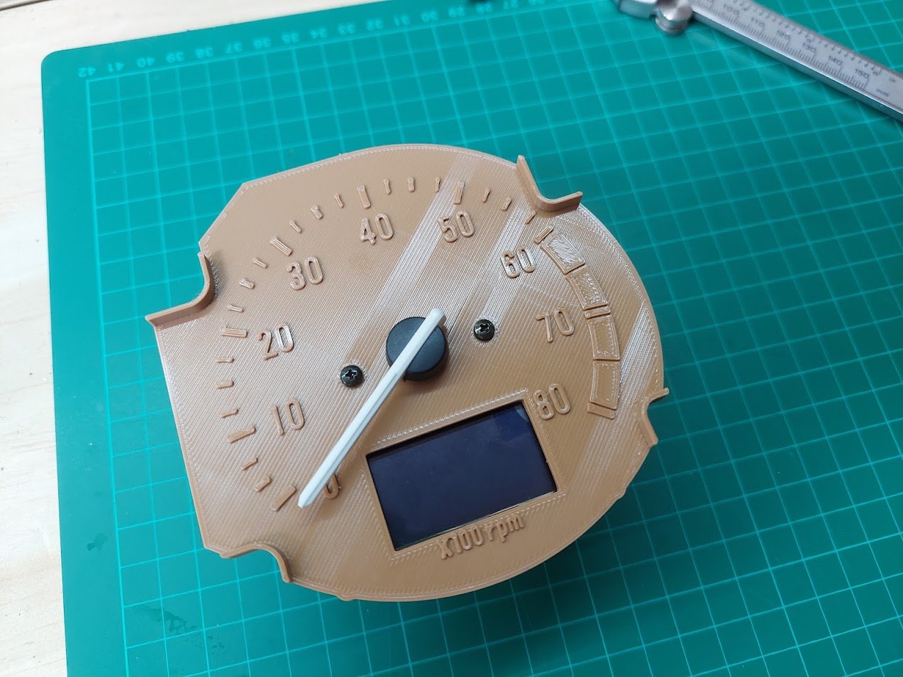
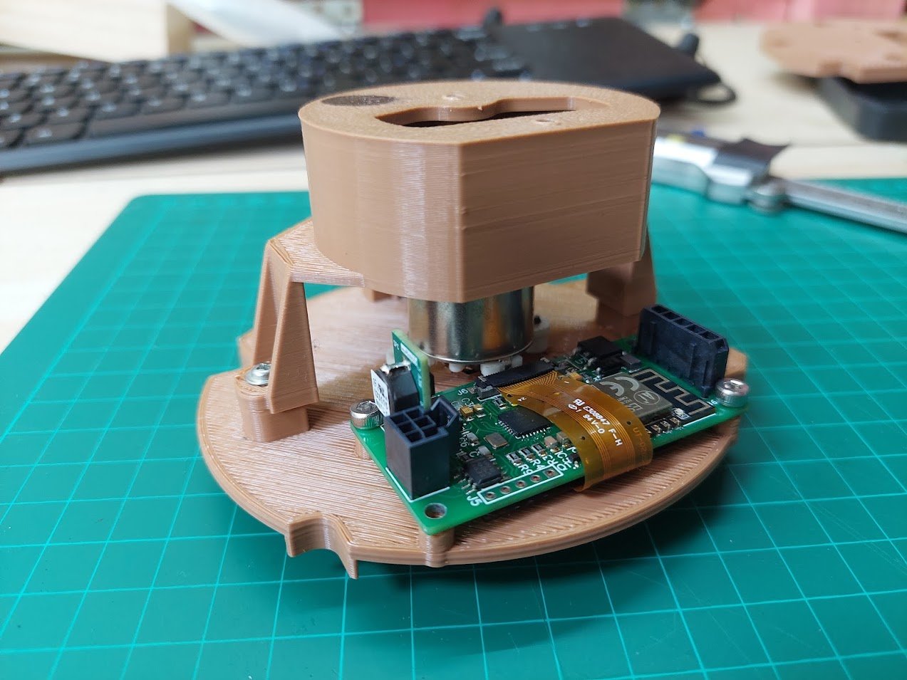
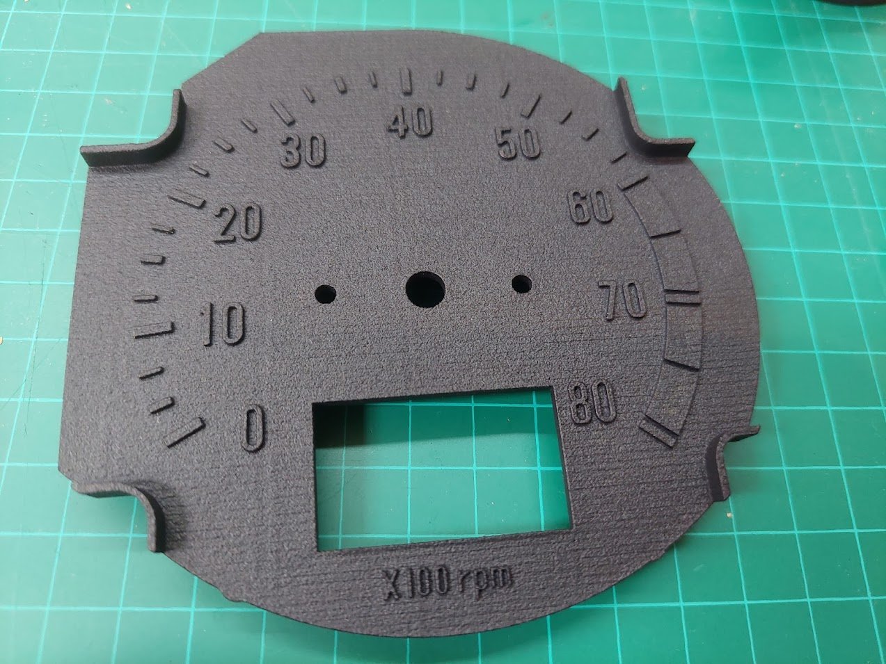
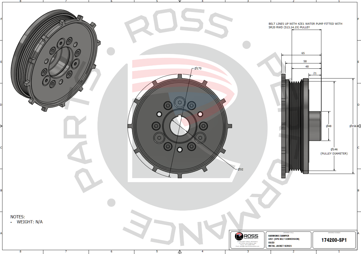
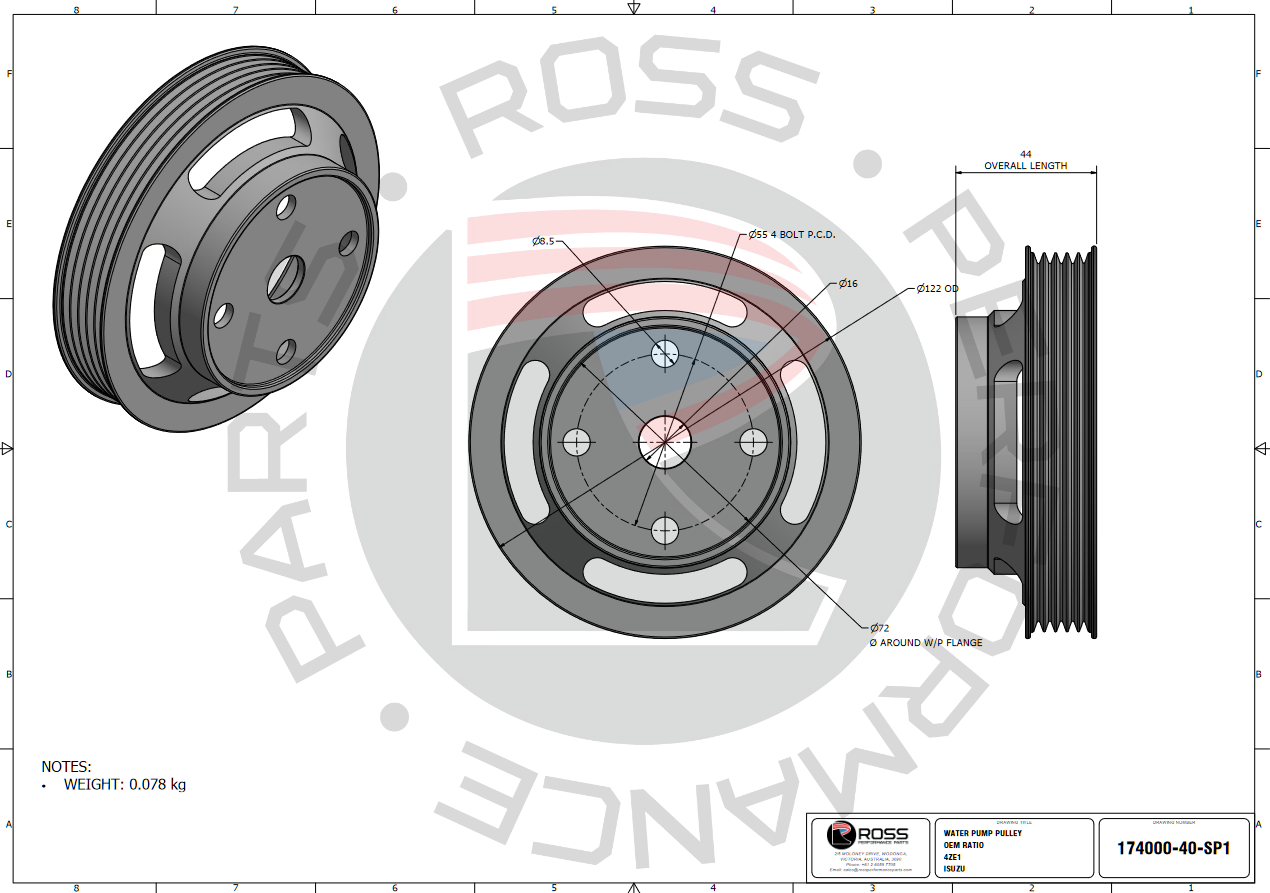
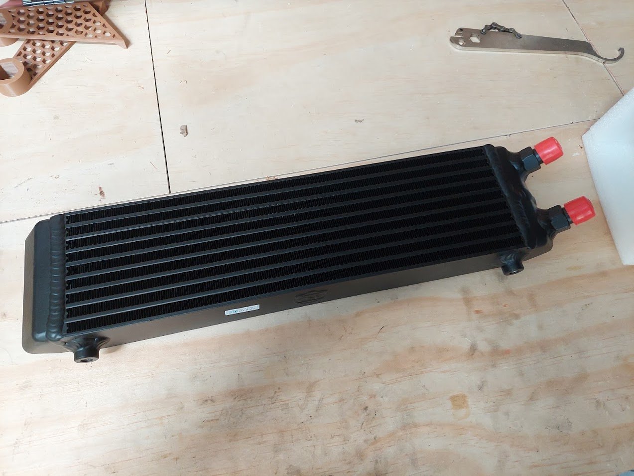
Wow! I really haven't updated this in a while. There's been a bit of progress in the last 7 months, but not a heck of a lot. I've been mucking around with brakes, dashes, diffs and cooling. In the end, I decided that shortening my axles the "build up and machine down" way was going to be okay, so I sent them to Howat Engineering and had 35mm lopped off and the splines cut back on. I then took the housing to Tin Tricks where it had the Gemini mounts cut off, was shortened and had the 4-link brackets slid on. I left the ladder bar mounts on so it still had a way to mount to the car when I had to move it. Turns out I was spot on with my measurements. The wheels just sit inside the arches - will need some work done to get unobstructed bump - and I have about 15-20mm clearance on the inside. So pretty happy. I've also spent a bunch of time prototyping up some parts with the 3D printer. Throttle body adapter: Brake caliper adapter: Master cylinder adapter: And for those of you who recall ages ago I was trying to make a new tacho face for my dash, I've gone in too deep. I've designed and printed up an adapter which uses all the stock mounting points and screws, as well as a new face which has the cutout for my CAN screen: I then had it MJF printed in PA20 nylon. Unfortunately it warped so I need to have another go and add some ribs in to strengthen it. I was planning to paint it myself using modelling paints, but I'm not sure that I have the ability. I spoke with Charlie's Pinstriping out west who said they could do it. When I get around to fixing up and printing a new version I'll take it up. Last thing that I've been doing for quite a while is working with Ross Performance in Australia to develop a harmonic damper and water pulley for the Isuzu 4Z engines. They have pretty much finished, I'm just waiting on one or two people to test some 3D printed templates to make sure everything lines up. And lastly I have been talking with Skeleton Welding down south to build me a new radiator. It's been a bit of a packaging saga to try and fit the radiator, intercooler and oil cooler up front. But I think with a bit of ingenuity I'll be able to make it work. Speaking of the oil cooler, I got this "cool" one from CSF: The car is now in at Shores NZ having the 4-link boxes welded in and the rear turrets strengthened for coilovers. So progress is happening!
3 points
-
Finished bolting in the fishnet recaros this morning while waiting on materials to arrive. also picked up some wedge lock washers for the brake discs. I don’t know why, but the hunter brake hoses fit the escort calipers, even though the internet says Theyr different threads. So what if Theyr cross threaded right
2 points
-
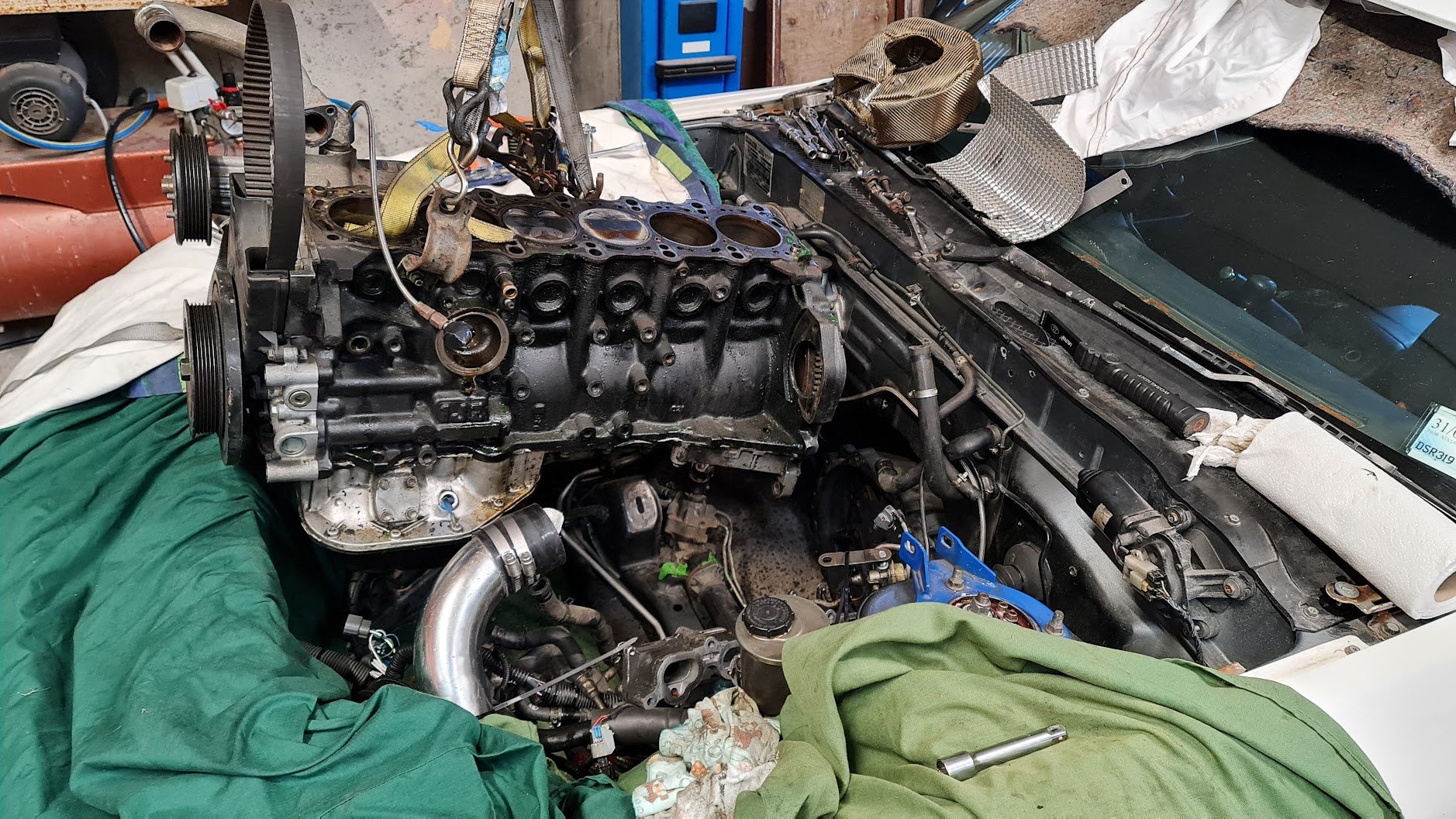
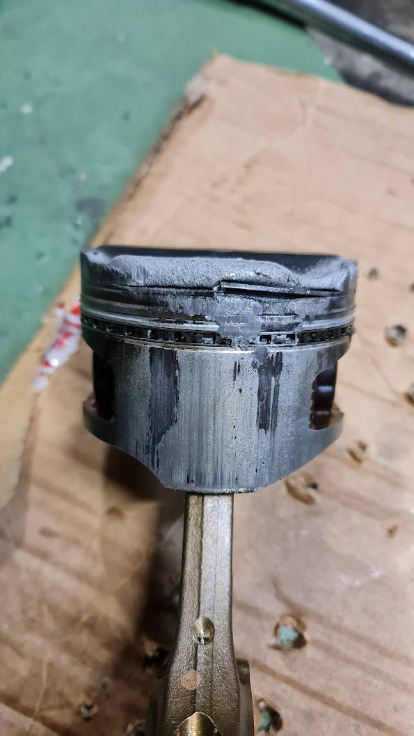
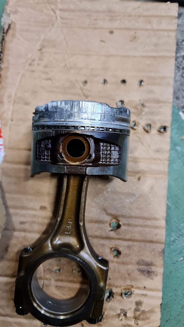
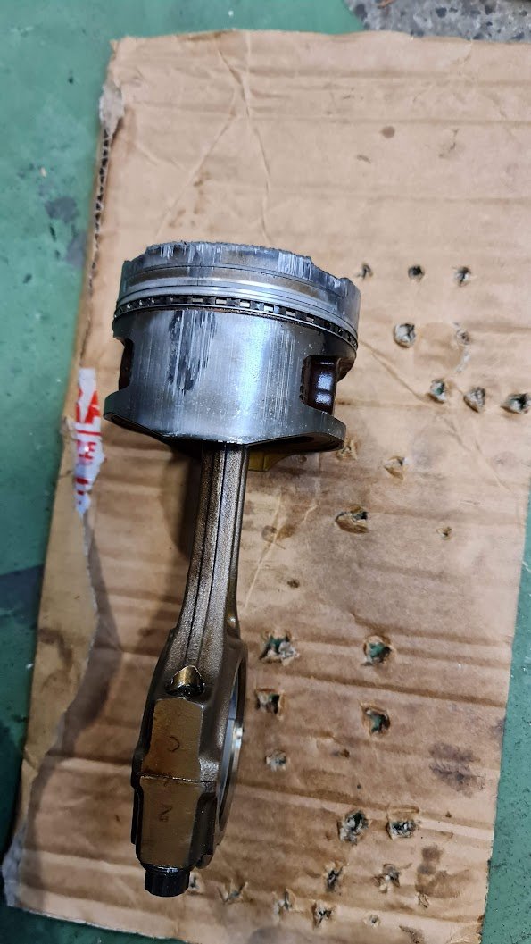
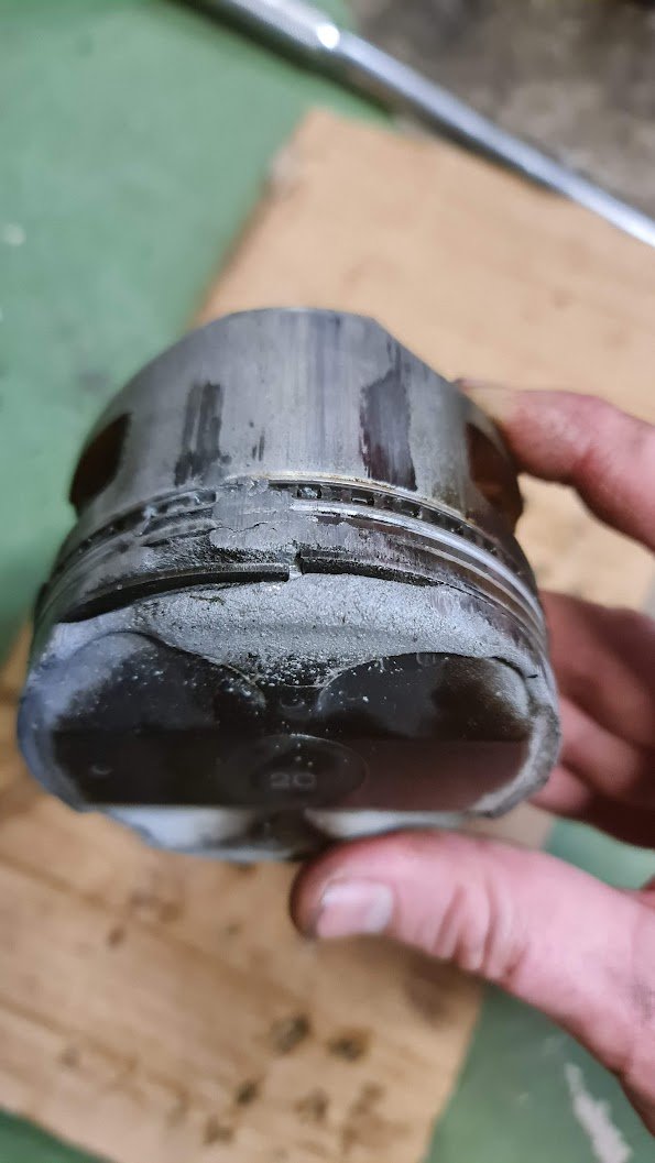
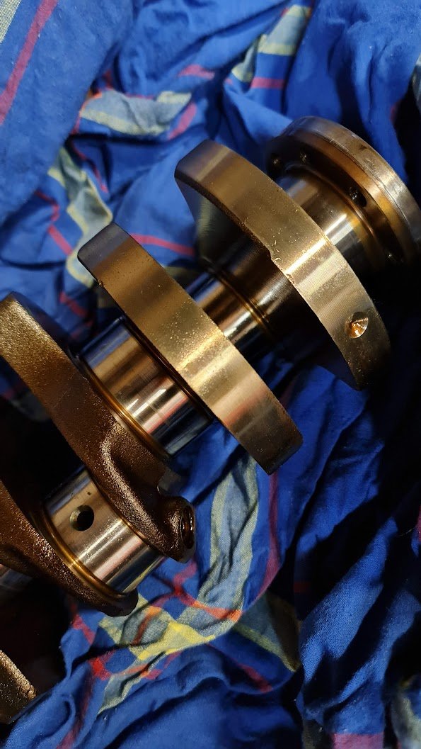
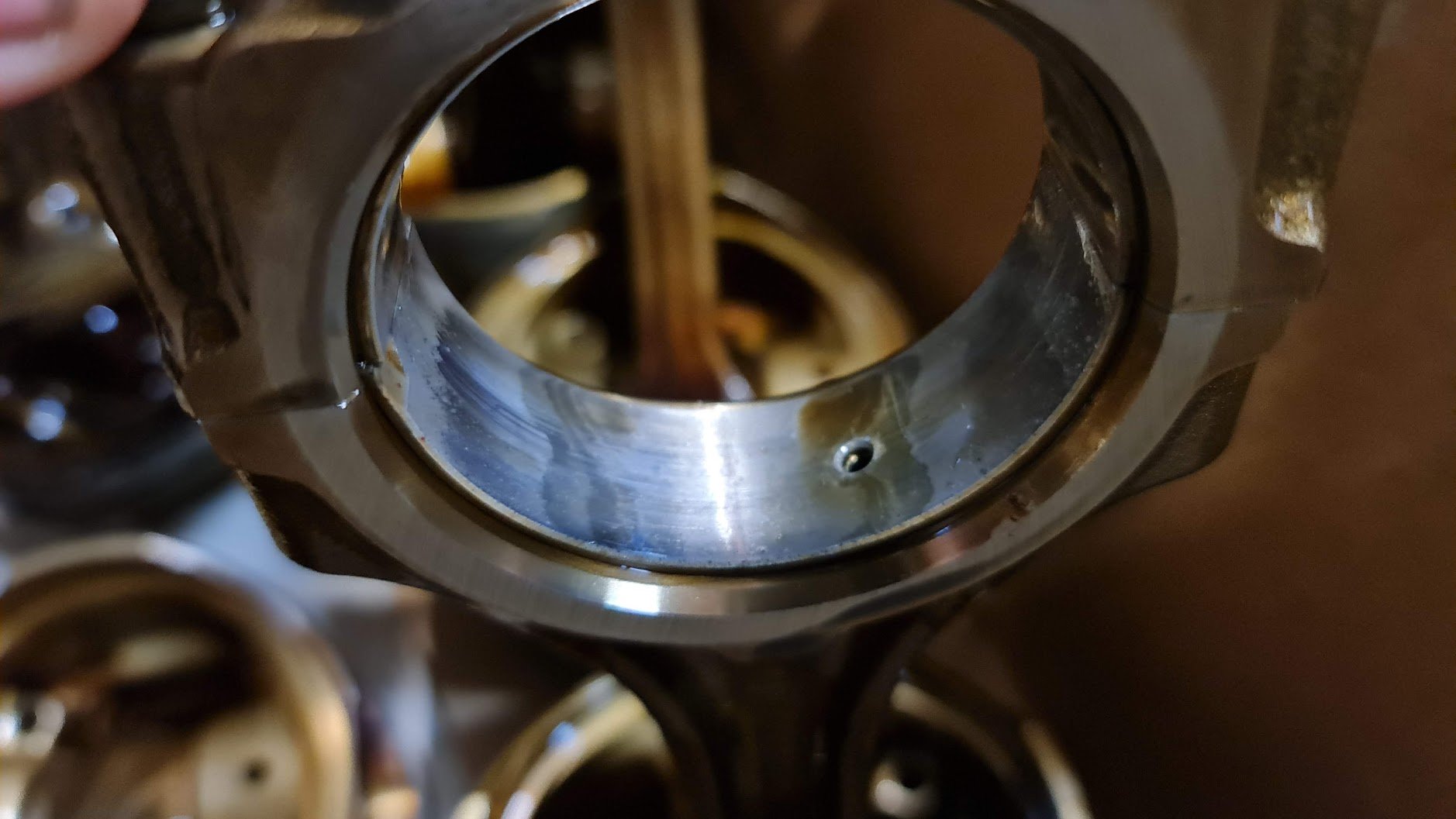
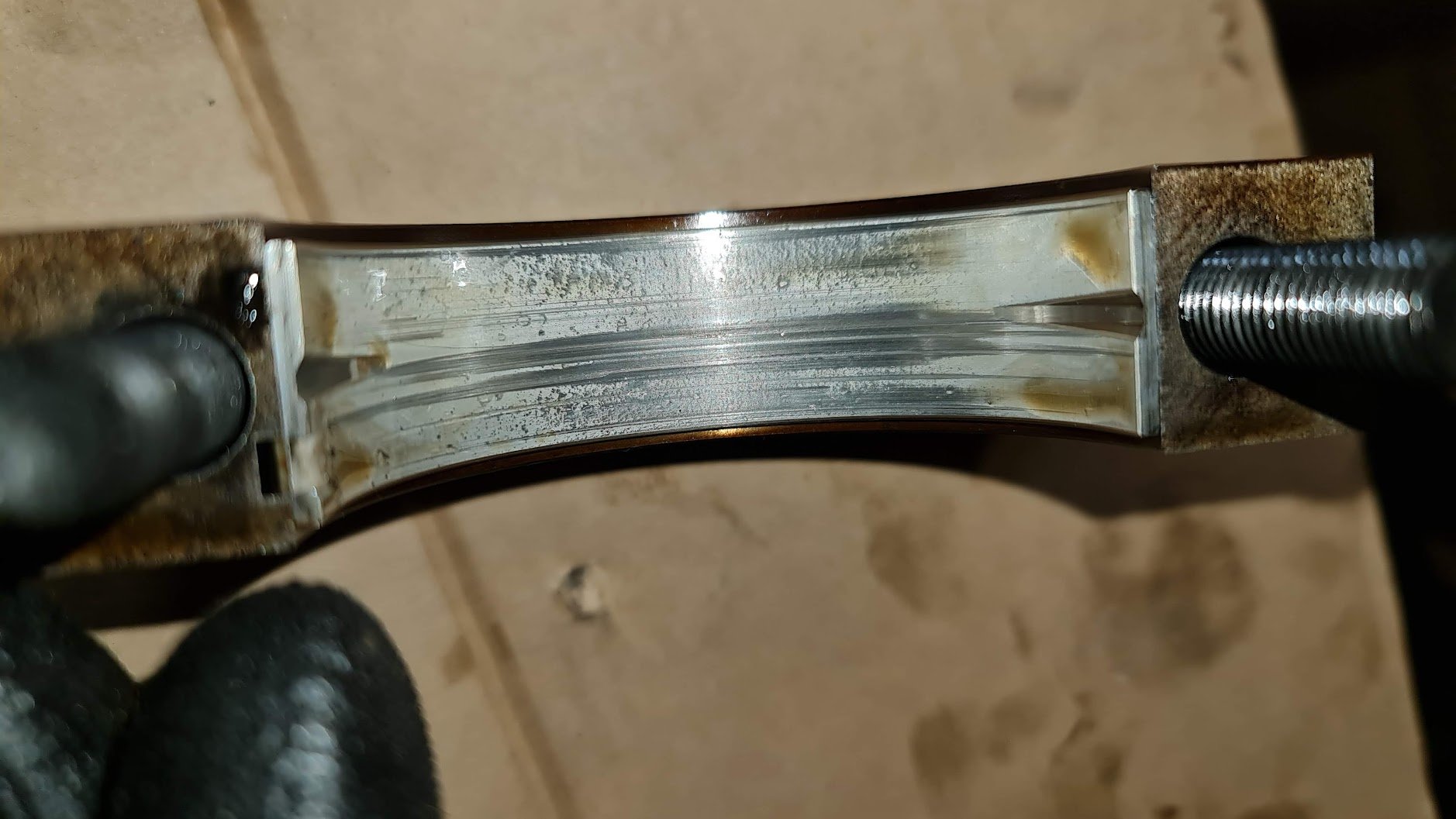
Automotive sadness ensues: The piston looks far worse than I expected. The ring lands look intact too. Another unexpected thing is number 2 had what looks like corrosion on the bearing? And some of the others have scoring which is maybe piston material going through the system since I can now see that the piston particles/melted bits worked their way below the rings. Everything went pretty smoothly with the disassembly except this one bastard allen bolt on one oil squirter. It was so tight that it rounded the inside of the allen head. I ended up having to chisel a groove into it to use an impact driver. No other damage though so just need a replacement bolt. Going to send the ECU off to Link to see if they can test the injector driver on number 4. Will contact to find out what can be done, even just paying to have it replaced just incase. Dropped the injectors themselves to be tested late last week.
2 points
-
2 points
-
last on the road 2007 ish. spent about 7 hours on it today.
2 points
-
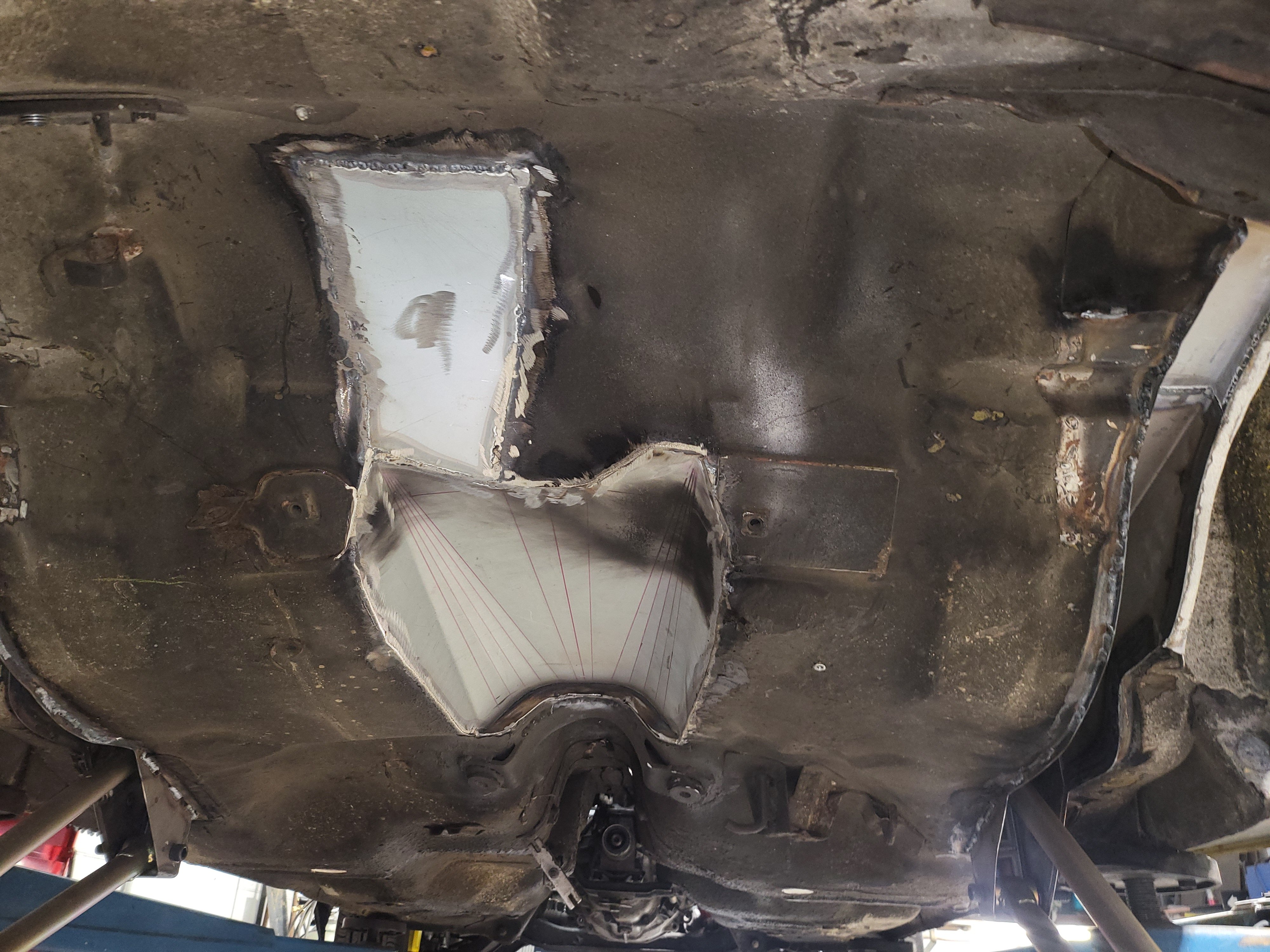
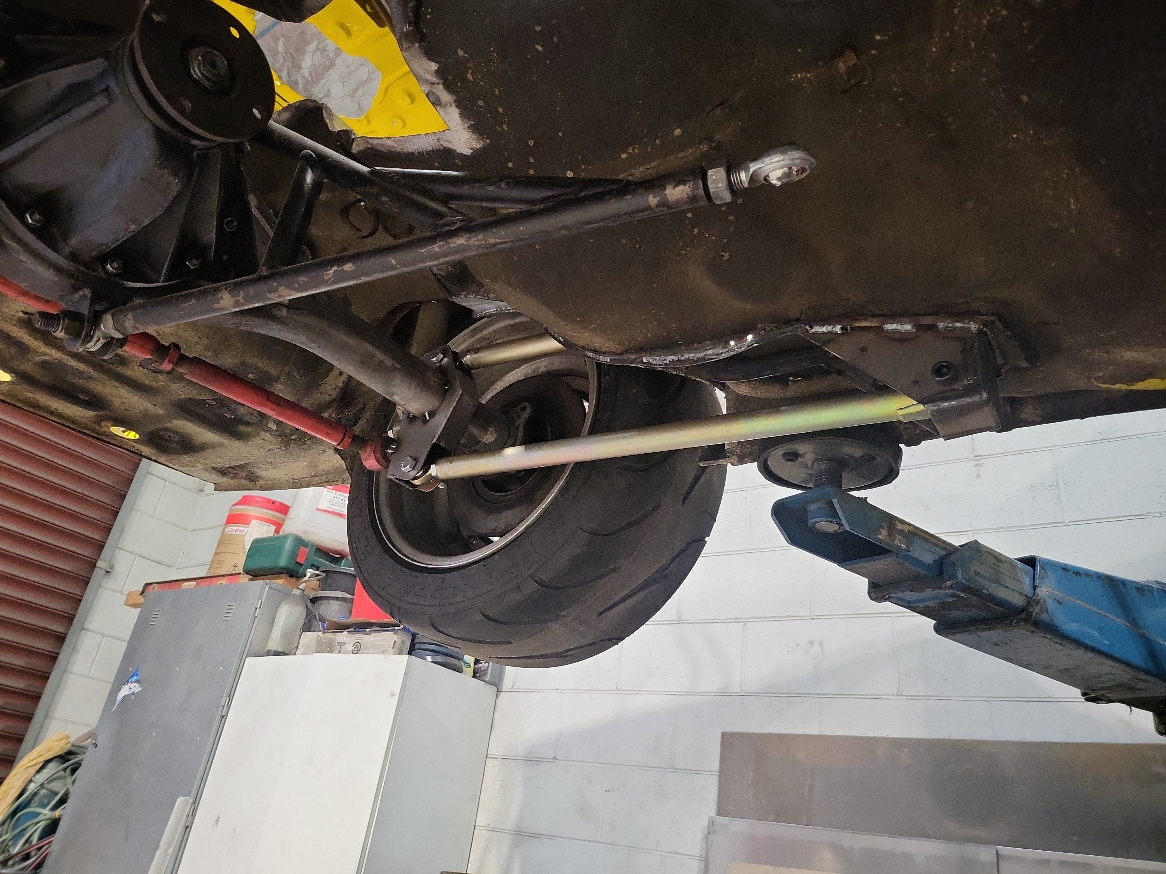
Almost done with the 4-linking. Tim has opened up the tunnel so nothing can hit at full bump, and closed up the channel that was cut for the old ladder bar.
2 points
-
brought this off trademe, picked it up on friday. mileage not really known speedo has been replaced at some stage. 1987, blake plate, on hold. painted the frame on saturday with a rattle can.1 point
-
Looking at the wiring diagram for the regulator, I haven't wired it up properly when i tested it. Will have a crack on wednesday and see if that helps. Wonder if the regulator has been damaged (either by me, or by previous owner). However, the fact it still doesnt generate enough voltage to require regulation has me scratching my head. A bit too late now to go and fire it up.1 point
-
weird texture on the bearings can be signs of knock. i assume number 4 big end bearing is a pretty beaten up? what do all the others look like?1 point
-
For a older traction control system it actually works alrite in the wet doesnt just kill the power,still end up turning it off for true fwd experience1 point
-
That usually required if there is zero voltage output and no shorts internally. I gave it a flash anyway, same diff. I flashed it the other way and it makes a negative voltage. So magnet is working correctly. Just output it low.1 point
-
Here you go, looks like it's still on special too https://nzairfilter.co.nz/davies-craig/8907.html1 point
-
My 351 Clevo had similar issues getting hot when idling for long time or slow traffic on hot days. Turned out to be the wrong thermostat for 351C in it so when hot and open the hot water still circulated through the heads to get even hotter. -May have had 351W thermostat in it? Swapping to correct thermostat helped heaps as bypass then properly blocks off to send hot water just to radiator. Now runs much cooler stationary on hot days and going up slow hills. I see you have already tried a couple of different thermostats, but not sure if your engine has similar set up where the thermostat could be mixed up?1 point
-
That the guide i've been using. Seems super useful. Although now my output readings are not in any of his lists. Looks like there are 3 options. No voltage output, 1-2voltage output, or working fine. Mine was 1-2volts first which pointed to armature. So now with new armature it somewhere between option 2 and 3. Its making voltage, but not the required output. So now i've got no idea what's wrong with it. After I put it all together, I popped 12v on it and it seemed to motor fine, in the correct direction too! I did the resistance checks, and i'm getting about 6ohm on the field and about 6 ohms through the output. So the resistances seem to check out fine... I'm just running unregulated for testing just to see the max voltage it can produce. If I connect it to the regulator I get about 2volts out of the regulator. Its one of these modern solid state regulators for dynamos. Wondering if this is poked also. Maybe it will work if I connect it all up how its meant to run etc. Will try that tonight. Im gonna rage quit on it for a bit now. I was really hoping this would fix it. Its not like it will be ridden at night. And now its got a mag, it doesn't need any charge to run. So perfect for sunday rides. I just really wanted everything on it to be all working properly.... maybe need to look for another dynamo for testing purposes.1 point
-
have a read of this if you haven't already. https://www.matchlessclueless.com/electrical/lucas/testing-lucas-dynamo/1 point
-
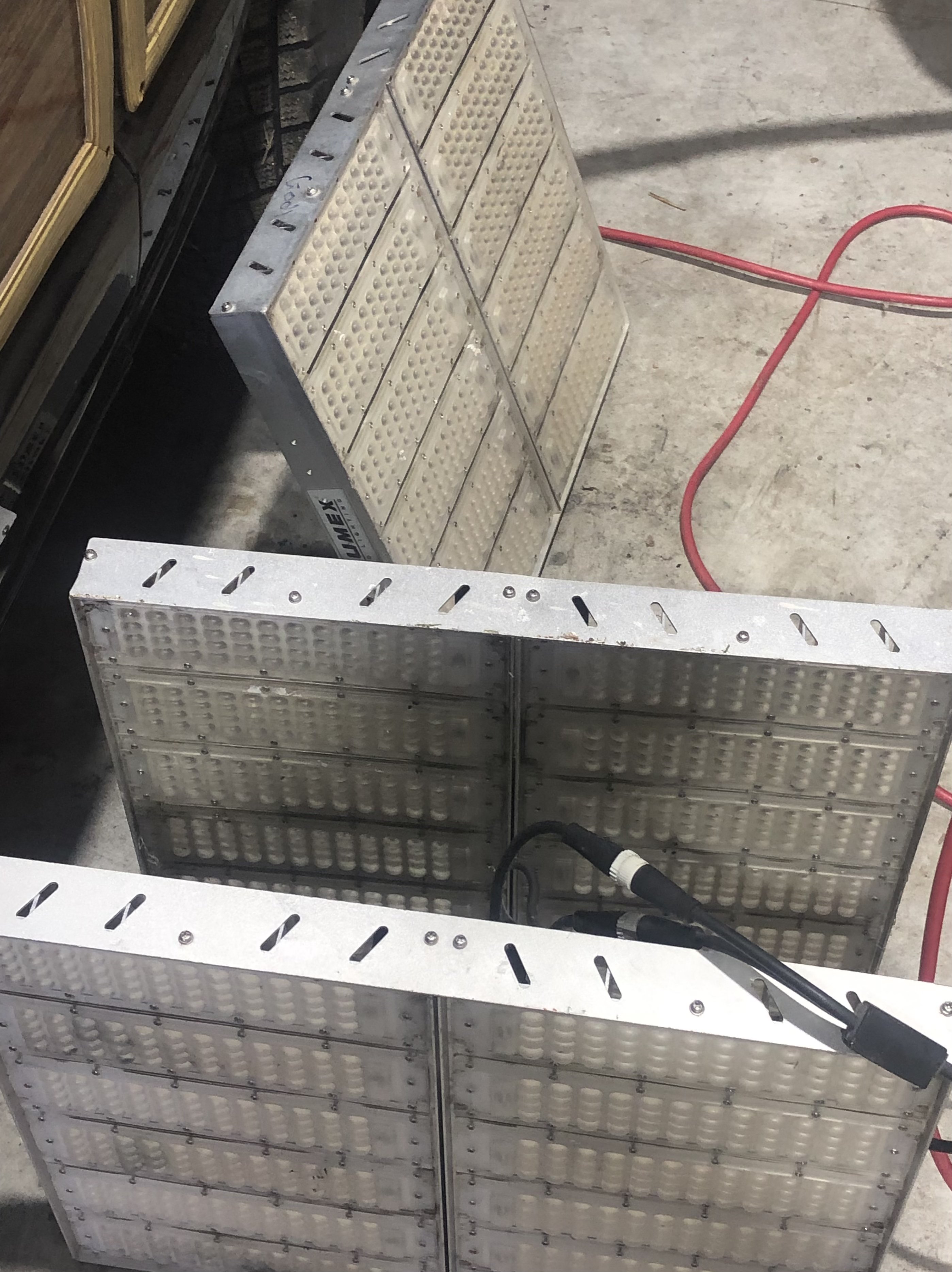
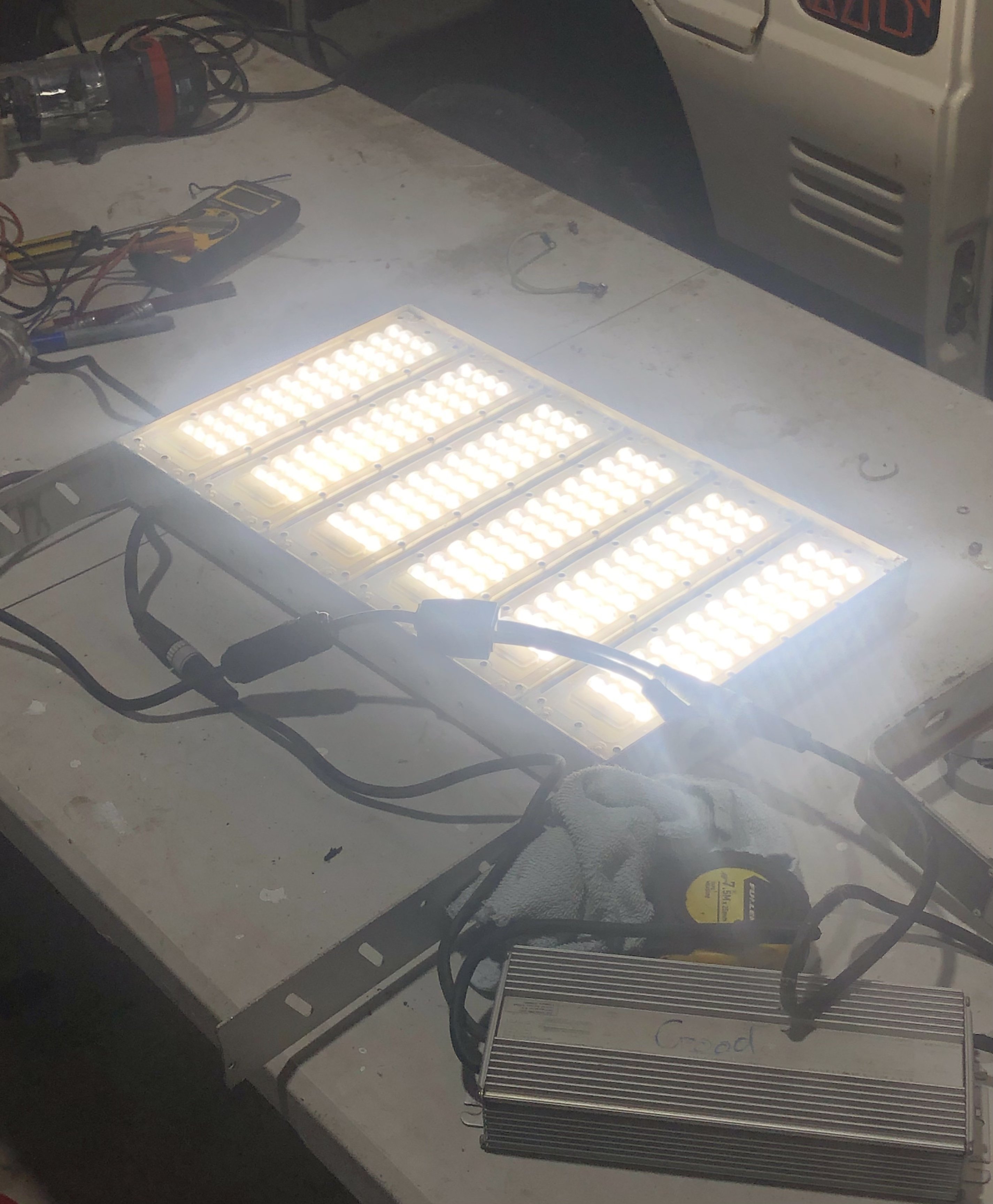
There are about 50ish of these going in the skip this week, ex stadium leds, however quite a few of the drivers have blown but the leds are mint, are they worth salvaging? The new drivers are over $300 on Ali. Each big panel has two lights and two drivers at a total of 600w. They go hard for what they are, will sling a few up around the shed
1 point
-
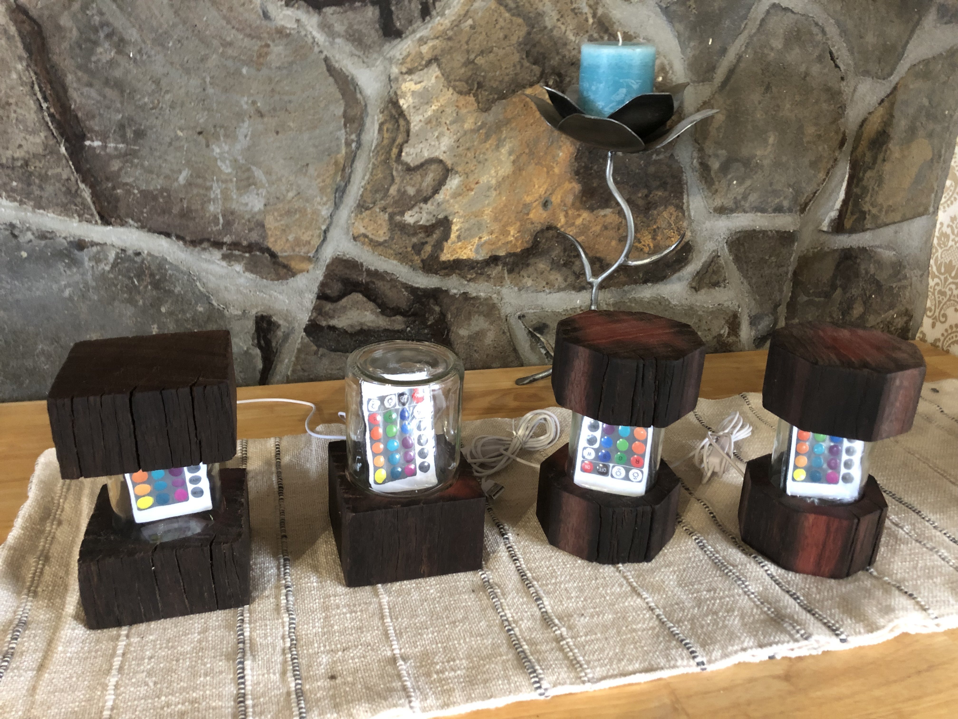
Ready to take to the local craft shop
1 point
-
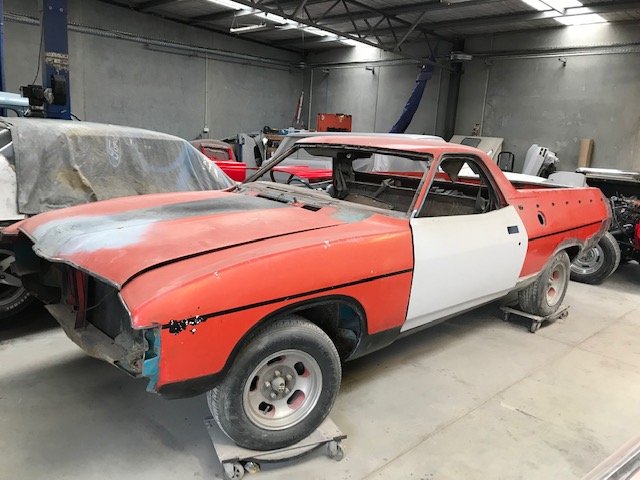
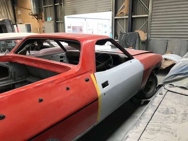
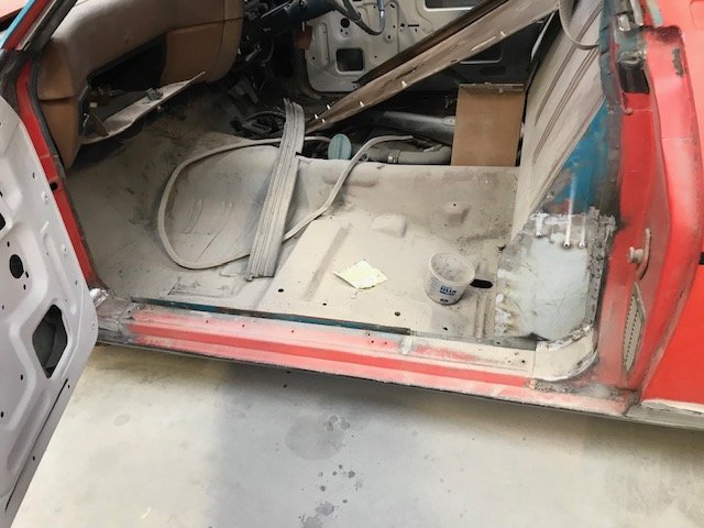
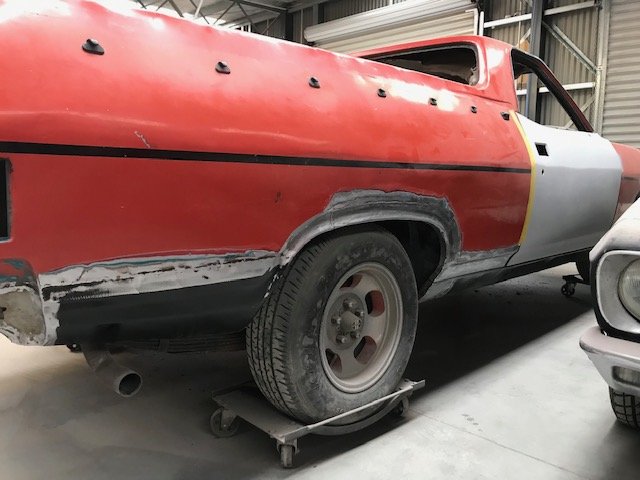
The photos so far are where things were left at Christmas, with the assumption that this would end up dismantled and forgotten in the shed. Was surprised to hear a month later it had been lined up as a downtime job at a local panelbeater and was dropped off shortly after. Got to see it a couple of weeks ago and there’s been decent progress: Replacement doors sourced: (For those following from the discussion thread -@Lord Gruntfuttock and @locost_bryan - think these were out of an XC coupe, and he’s deciding whether to tweak for XA handles or just going with the XC ones). Minor repairs to each door step: A tidy up of the quarter panels etc:
1 point
-
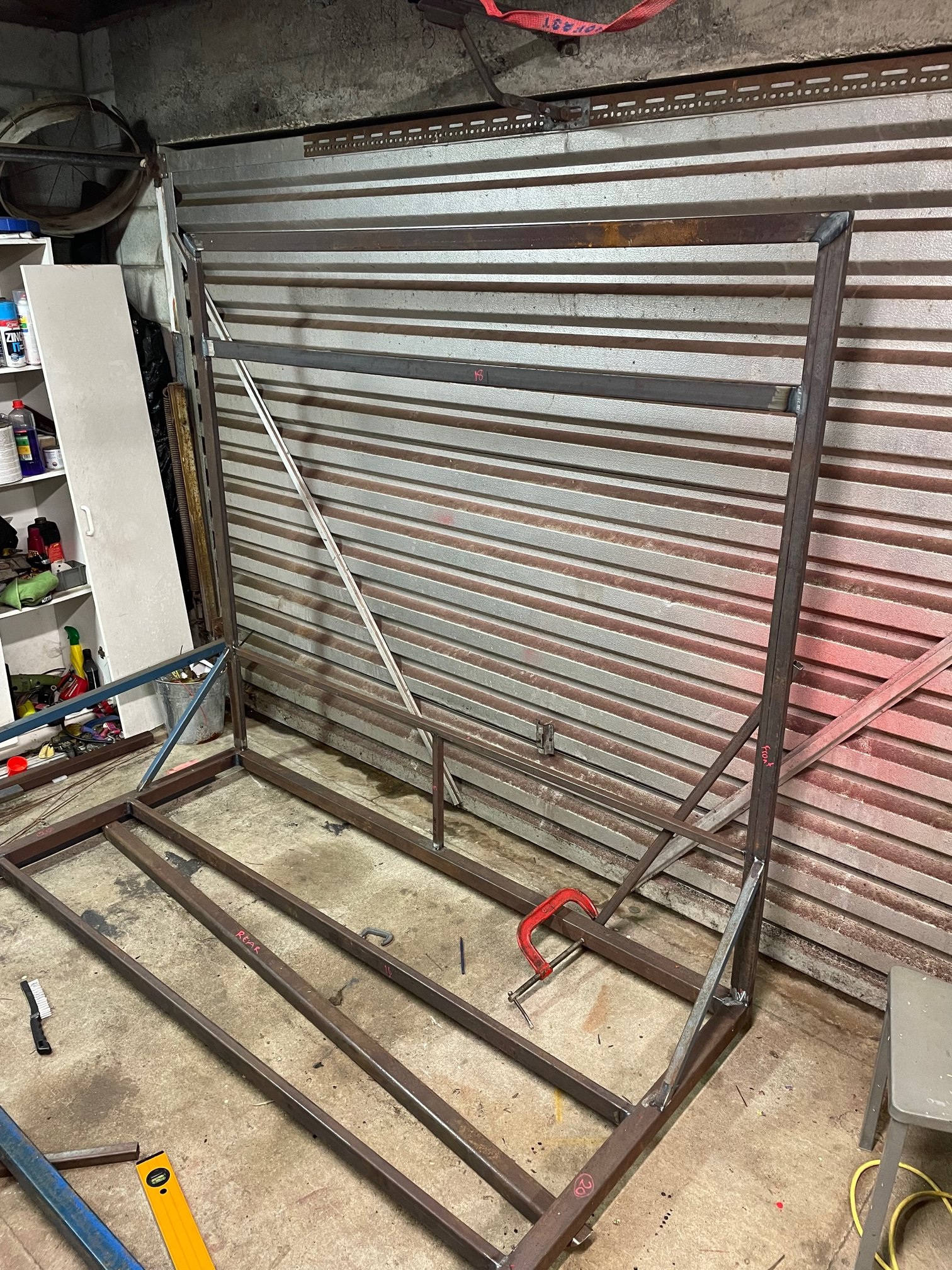
Got a wee bit more done last night. Tacked the other bars into the front section and welded out the top part. Thought it might be easier before the upper framework goes in. I didn’t want to start fully welding the bottom and bracing until the top is restrained. Also got the rear frame tacked up.
1 point
-
I can weld that no problems. Done heaps of shitty oil filled cast alloy stuff and it's fairly easy too. Probably be couple hours max in it. Good surface clean. Grind a big vee weld prep, go nuts here. You need a bit of room to get the tig torch to the bottom of the vee. Leave only 1-2 mm wall thickness at the bottom of the vee with the original break so it lines up perfectly. File the ground surfaces so it's clean, a grinder tends to rub and fold alloy over itself trapping crap in there. Good preheat to draw the shit out and final clean. With the tig tack it together. Here's where you need to take your time. Set the tig to a bit more cleaning than penetration. Strike the arc and puddle the torch around a big area. (Don't add filler yet. Castings are full of air bubbles and you don't want to try add filler wire on top of a bubble). Keep moving the torch around until the bubbles come to the top and the surface becomes smooth and shiny. Now you can add filler. Once all tacked in place, clean up any more oil that's come out. Then use the above technique to clean and weld the rest of the join. If crap keeps getting drawn through when trying to get a clean smooth surface then dial in a bit more cleaning on the balance control. Don't be tempted to chuck filler in there to cover it up, it goes pear shaped.1 point
-
And this one too: Skipped a bunch of steps...heaps of shit done to it. But long story short, it's a hybrid of old and new parts machined to fit and work together. Pretty stoked with outcome.
1 point
-
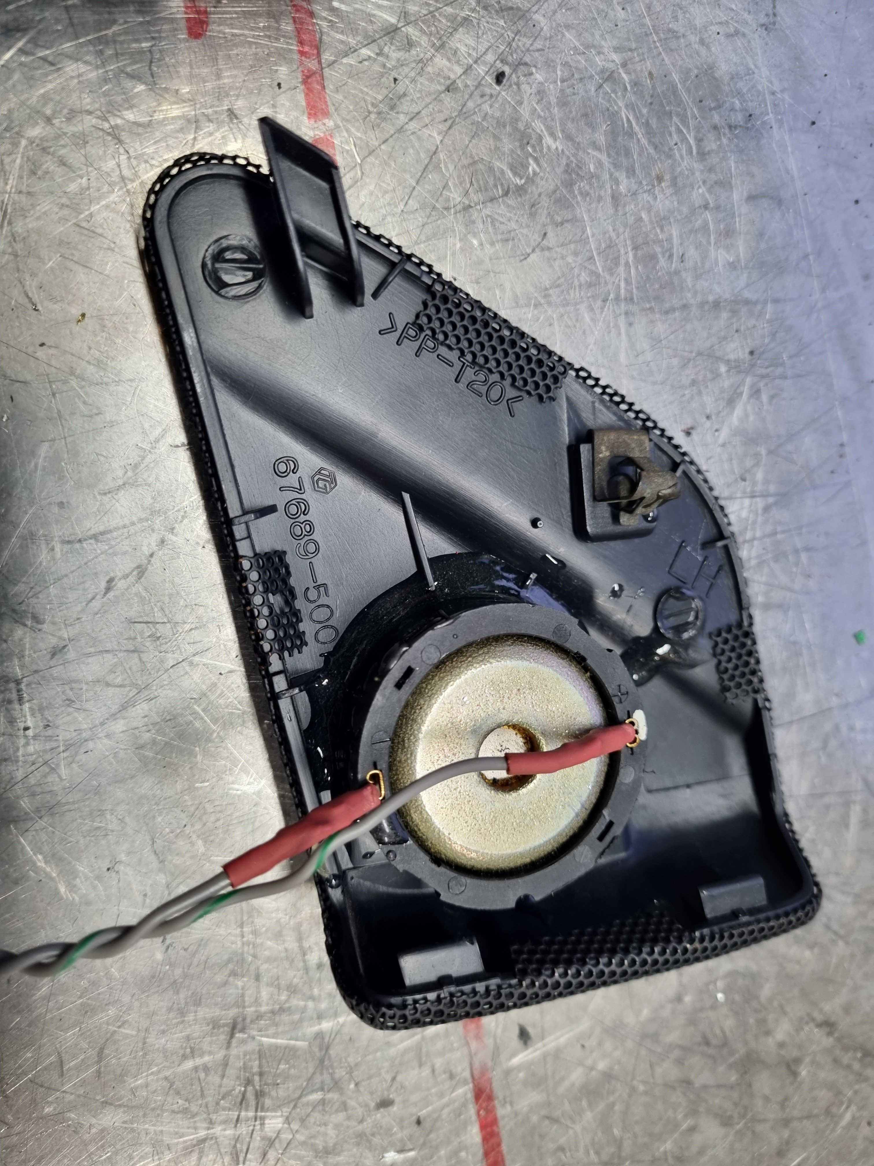
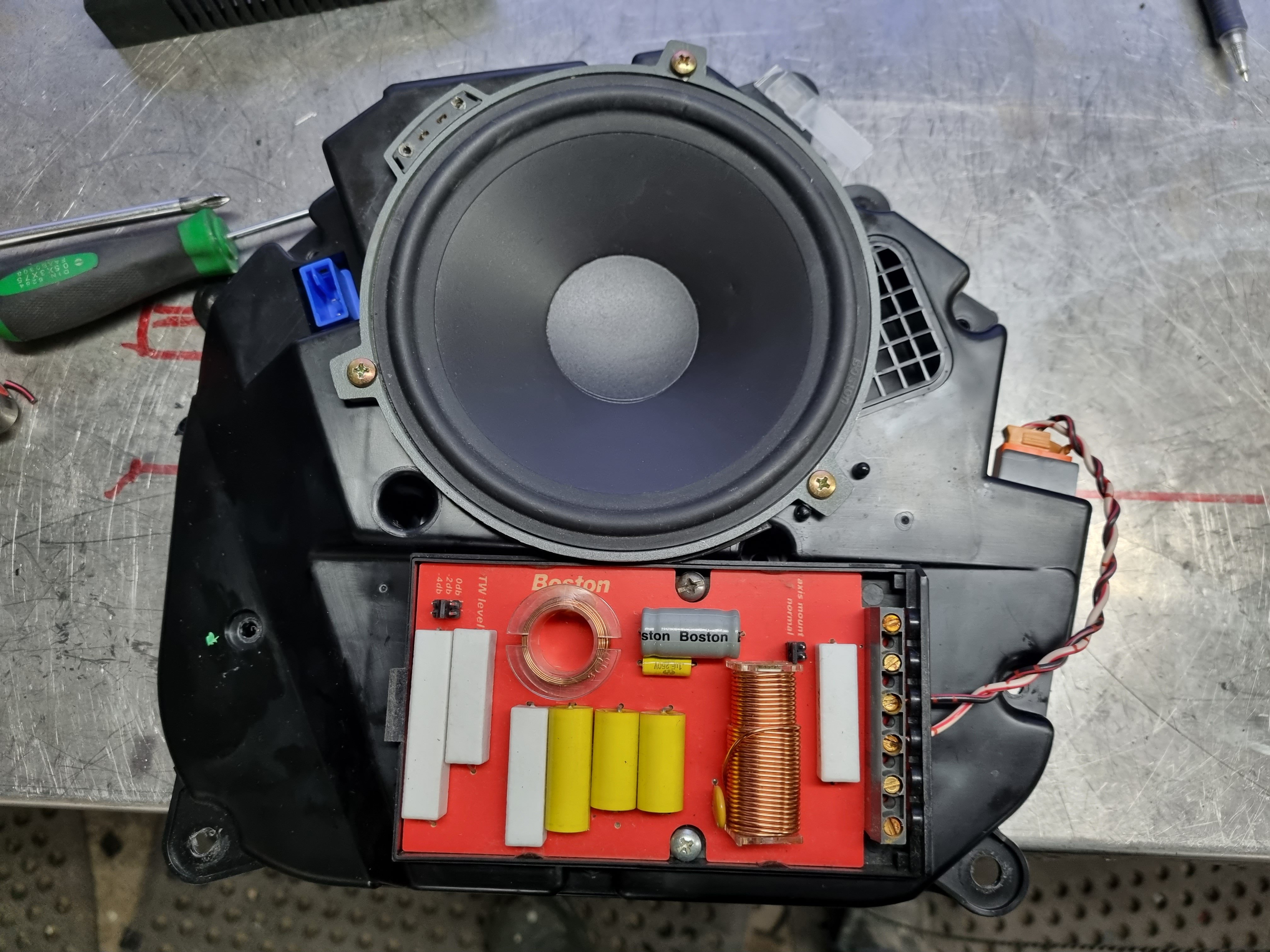
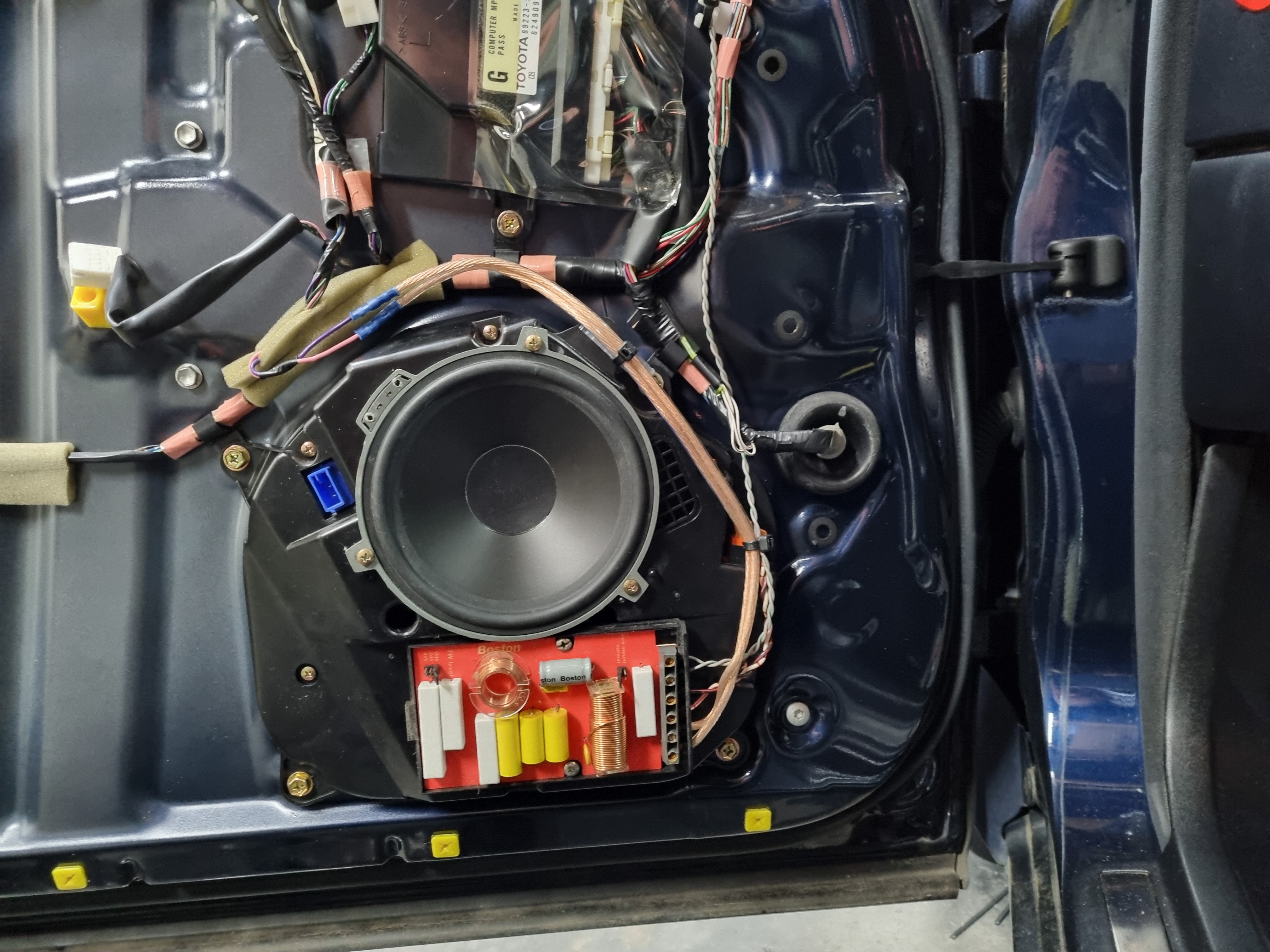
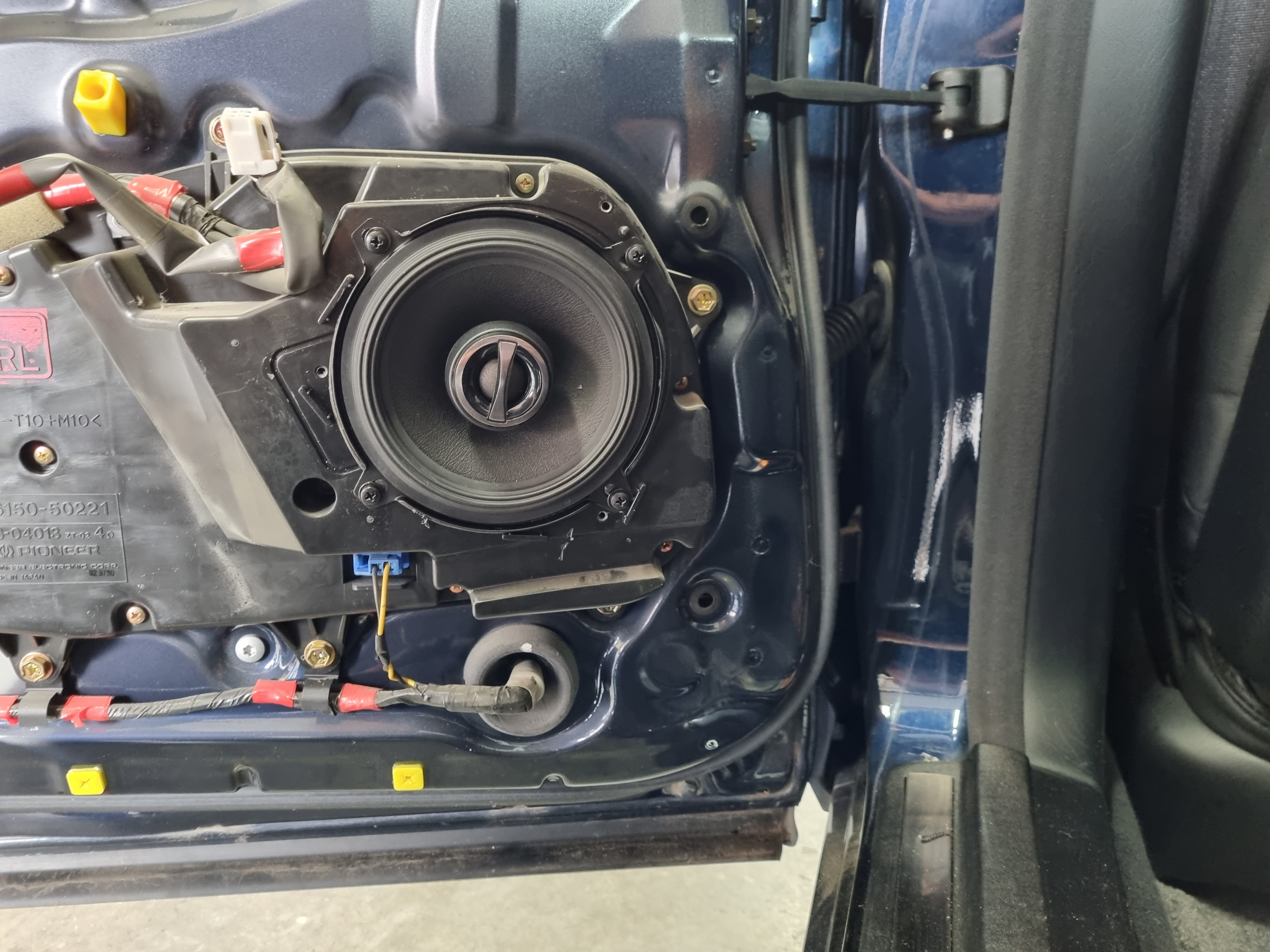
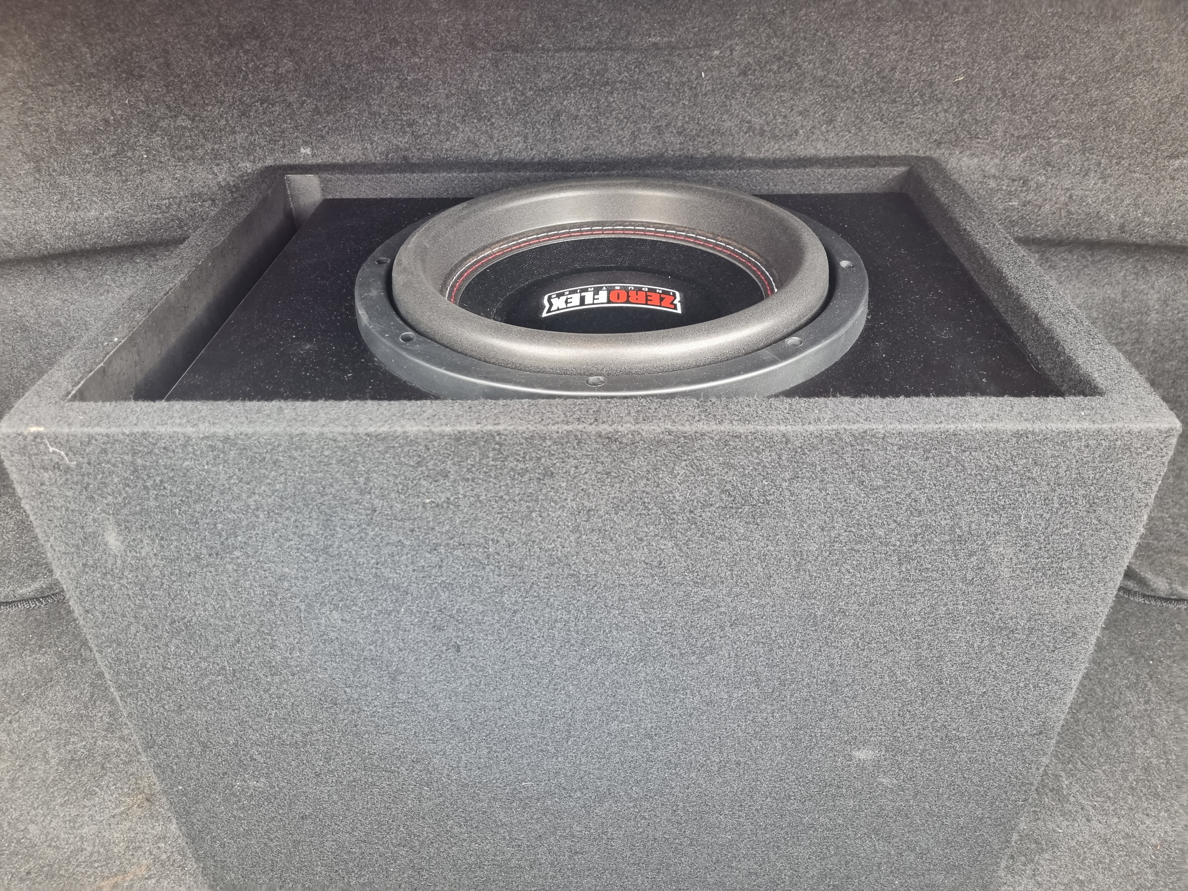
New stereo. Factory system was OK but no Bluetooth no hands free etc. So I replaced everything. Had to re route some of the factory loom and patch in a couple of wires but it was pretty easy. Running the power feeds under the car was the hardest bit, fuck I can't wait until I get a shed with a hoist. So anyway head unit is a kenwood one. It's got buttons and shit. There's a 100x4 amp under the drivers seat and a 600w amp running the sub. Front doors for a pair of boston 6.5LF pros that I've had for a while. Had to cut the hole or a bit to get them in but the rest was easy. Rear doors got some 5" alpine things that work great. Sub is a zero flex 10" which absolutely cranks. I'm still fucking with the steering wheel controls to see if I can get some basic functions working off the steering wheel, time will tell in that one.
1 point
-
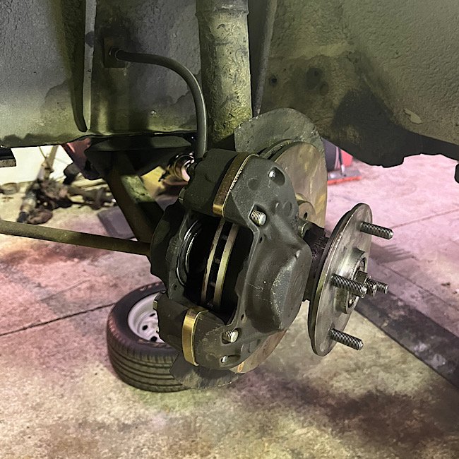
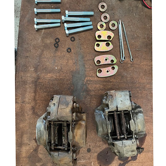
Have started on the front brake upgrade. first task was to fit a remote booster that would’ve come standard in these. id say the original had failed and was deleted on. so I salvaged one off a parts car I had. Got that fitted up. then sent my spare hubs and new capri vented discs off to Chris at suspension tech to get machined up. just need some wedge lock washers so I’m told. got a calliper spacer kit for the type16 escort calipers. these calipers are fugly, so have got a pair of rebuilt ones on the way. then lastly will need to get new hoses made up or an adaptor. Cert is booked in next month with Cletus, so should be plenty of time to get it back together.
1 point
-
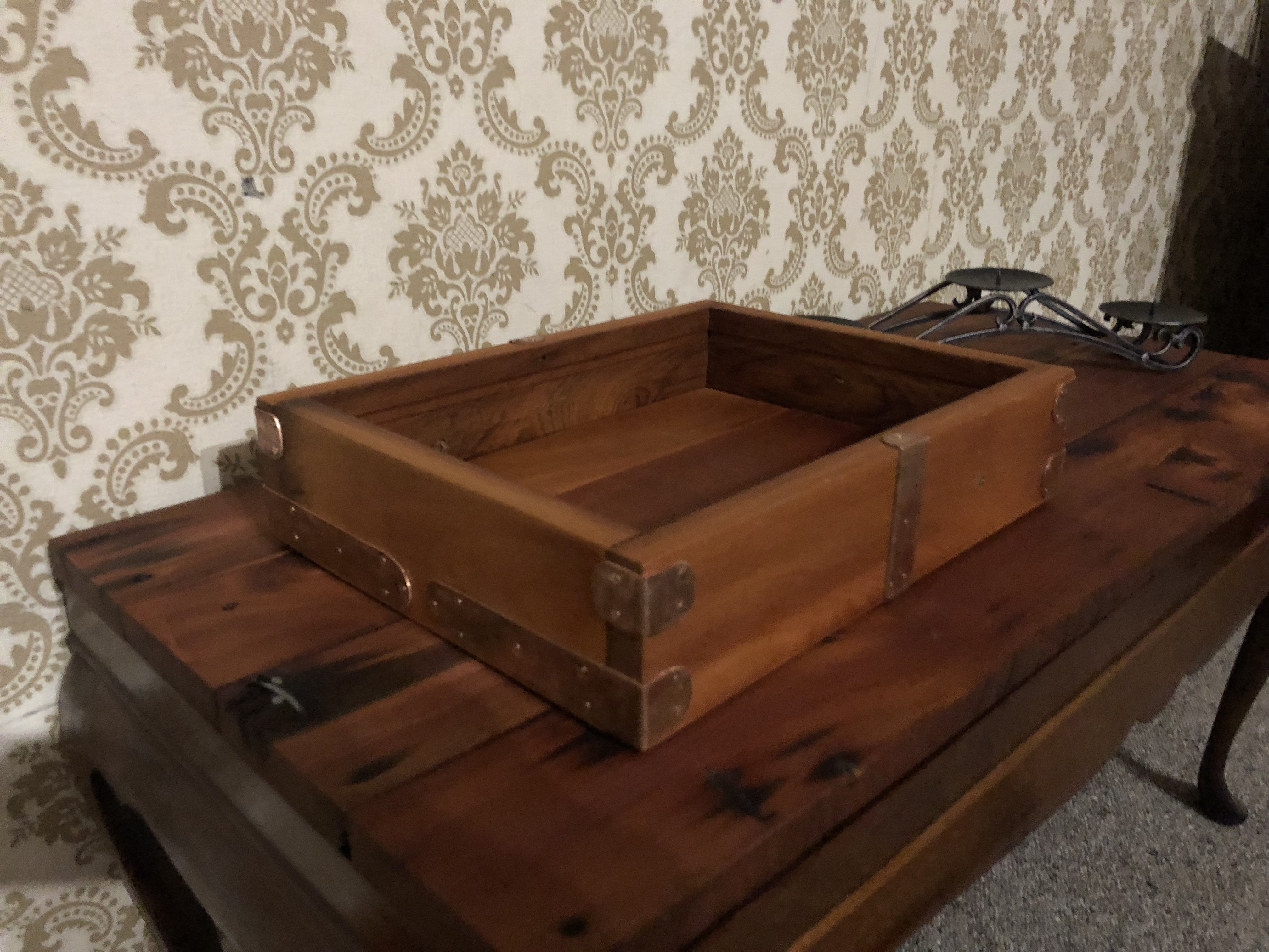
Made a little coffee table tray to put stuff in. I think the wood is Rimu and flattened some old copper pipe to cover the screws
1 point
-
About 9000rpm1 point
-
The water pump got pulled out in preparation for the electric one. It's a bit teeny understandably, impellor was about 50mm dia. Nice block off plate Don't worry, I got a new output shaft seal to put in. Then got a larger boss welded to the thermostat housing for the temp sensor. I got the electric water pump wired in but the screen was dead out of the box so now I'm following it up under warranty, boo. With that on hold I thought I'd have a play with some other shit. Fuck yeah accessories, got some fog lights and air horns hooked up. I got the horns tucked in nicely behind the plate. Then I was reminded how small this car is, the damn plate sticks out over the lights. Need a plate narrower than 320mm to miss them or find another spot for the lights to go.1 point
-
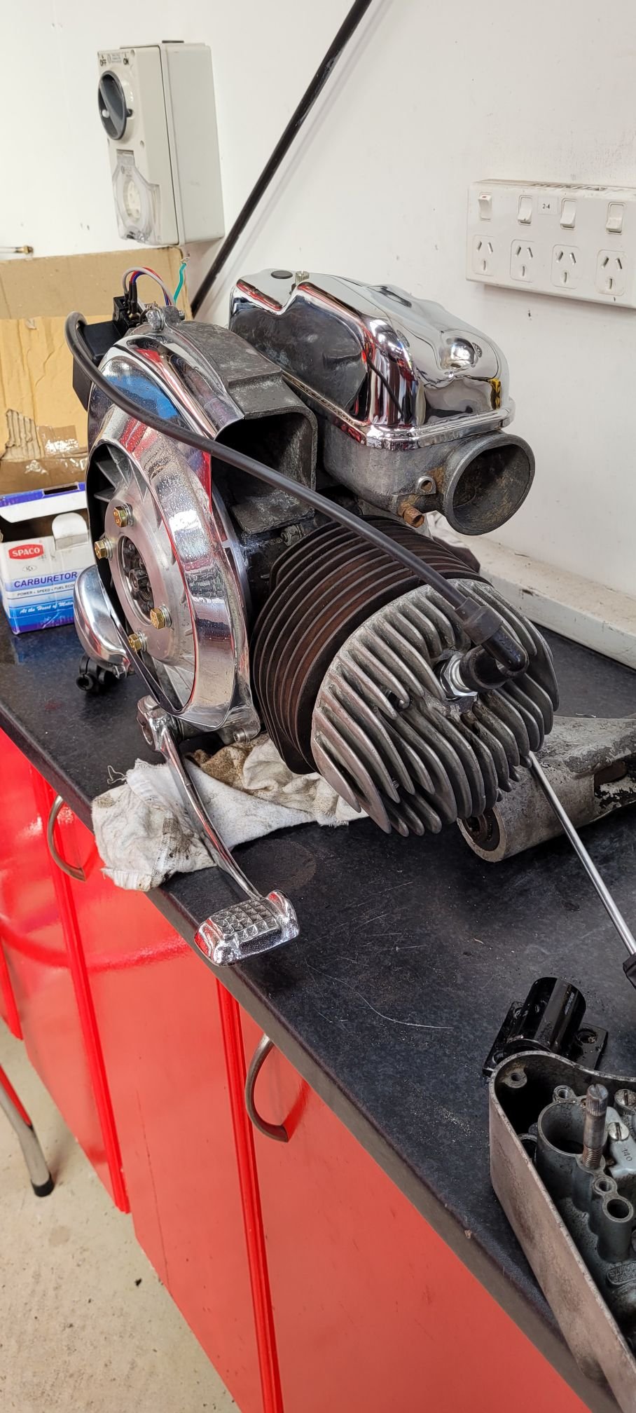
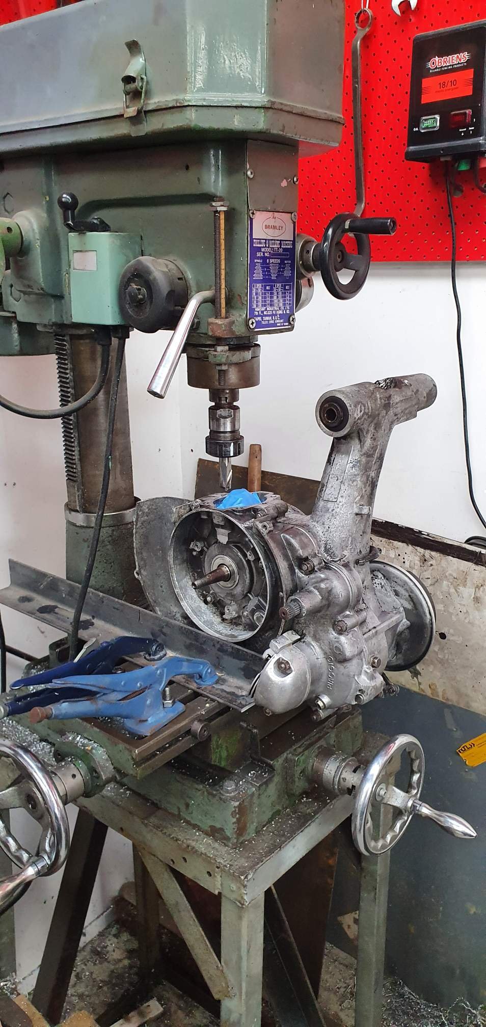
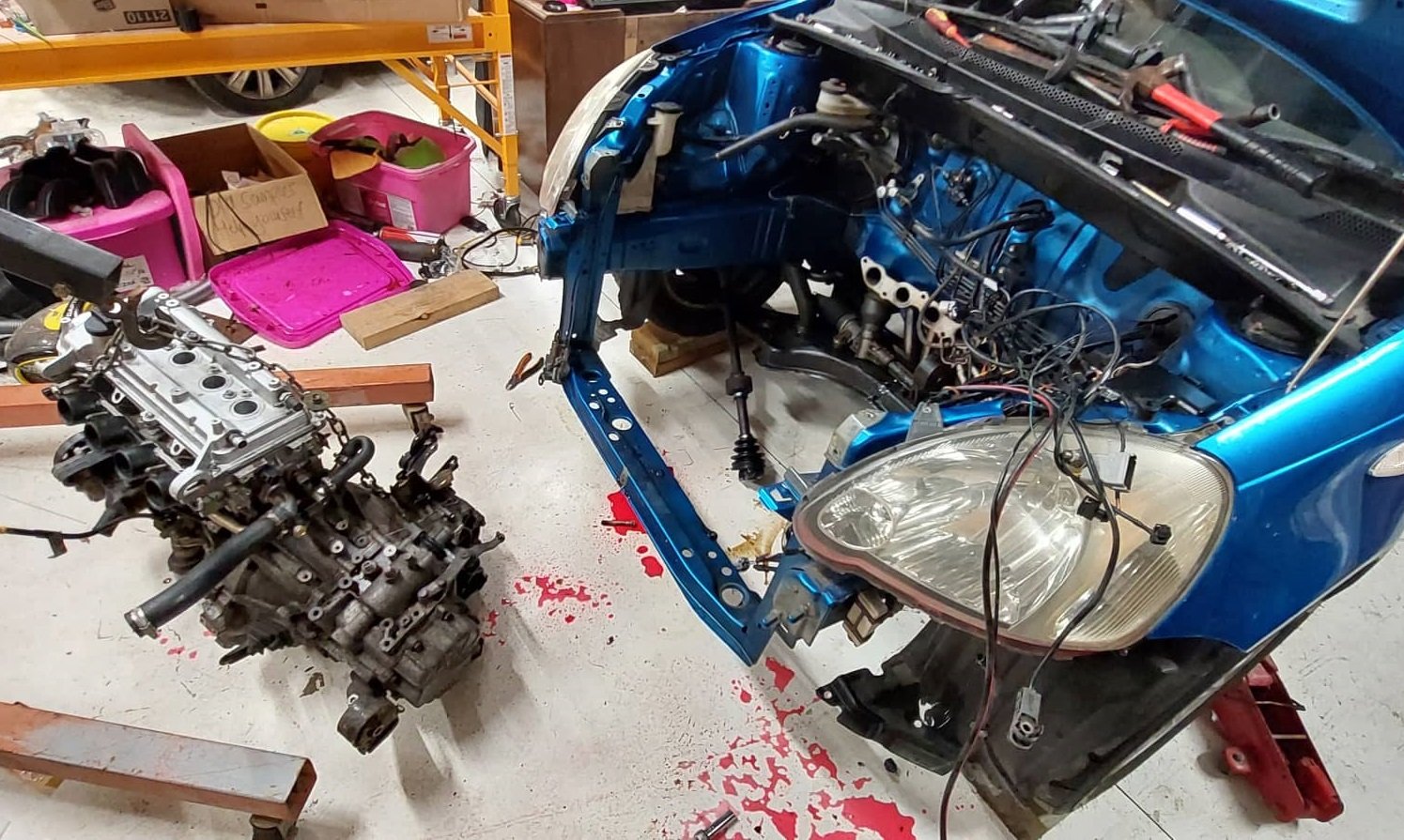
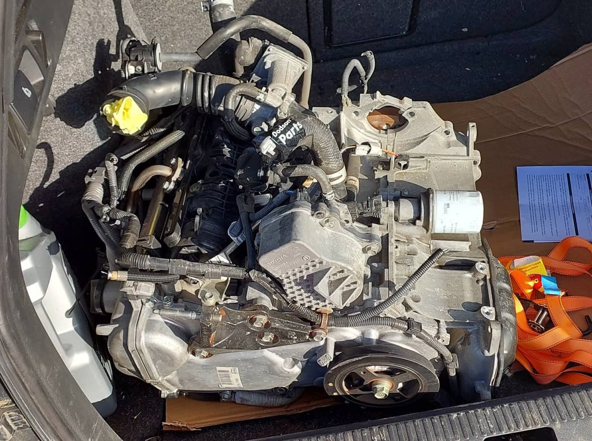
Picked new motor up! At risk of sounding like a broken record, thanks heaps to everyone that has helped. I am amazed and very grateful. So I stripped off all of the hybrid junk, and either way the head needed to come off. As I will either swap the other head onto it, or need to swap the valve springs and cams over. Then proceeded to get the 1300 motor out of there. I need to steal its sump to swap onto this motor. As I've done all these jobs previously it has been fairly smooth sailing this time around!
1 point
-
Definately. Plus the material itself is pricy. I justify it because I know if I don't pay someone else to do the hard stuff-i'll just never do it.1 point
-
Engine builder rang last night.. Any Rotor owner dreads the call from these guys.. "Hey mate, I pulled your engine down today..... And umm.................... " Gulp... waiting for the bad news that its a grenade... "It all looks good, ports are as rough as SH1, but the rest is mint".. This motor has also had its springs swapped out for rx8/fd springs, so they have more tension than a stock 12a stuff...will go well with the new unbreakable seals. So it turns out the porting is pretty average, so the plan he has for this is to turn it into a baby J port. Were going to swap the housings for the mint pair of RX2/3 housings I have on the shelf. Theyr already ported and notched. The ones that were in the motor will spin few triangles again, but have some peel.. do it once do it right ae.. I just have to drop my housings off, and flywheel so the whole rotating assembly can be balanced.. he wants me to run the lightened flywheel. Should go well.....poor fuel card1 point
-
Good idea blasting and powder-coating your cat, it looks good as new!1 point
-
Wow 4 injectors would buy me a k11!!! Also- lol at 731cc. One injector would be sufficient for more than the whole engines requirements I've been playing with some ideas and I'm already into a rail build. Update coming up fairly soon.1 point
-
One thing that i would check, is what happens when you try to change gear. As in, from 10,000rpm does the engine decellerate too quickly for next gear, or not enough? (Running g4x ecu? 1000hz Graphs plz) Adding a clutch switch and a gearbox speed sensor would allow you to setup flat shifting. This has a mode where as soon as you hit the clutch while at full throttle. It cuts ignition and or fuel instantly. So this cuts rpm quicker than waiting for throttles to ramp shut. As youre not relying on removing the air supply to drop rpm. So this might help if the motor isnt losing rpm quick enough. Then since it knows the next gear ratio it starts disengaging the cut as soon as you approach the right engine speed for what gearbox speed you need for that gear. The goal being to get the motor at the exact rpm needed. So it also helps if the motor is losing too many rpm. It dynamically adjusts the goal rpm, so even if vehicle speed rises or falls during the shift it gets to the right spot. Its fiddly to get the clutch point to the right spot. But it might help perhaps. Edit: thinking about it more I realize the above stuff might help your clutch but maybe not synchros while the clutch is disengaged. Hmmm. Might still be worth seeing if the rpm goes too high or too low during the shift period though.1 point
-
Things taking a little longer than I had hoped, but yesterday I got some good news. The 4-link boxes are in and I'll go and have look on Friday and figure out what the next steps are. I also heard from Skeleton Welding that my core has arrived, so should be getting that sorted to soon too! Pretty happy with the progress.
1 point
-
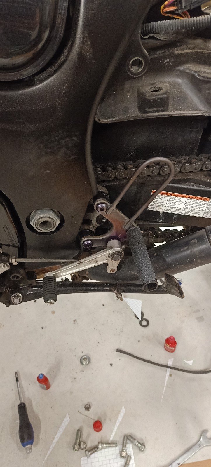
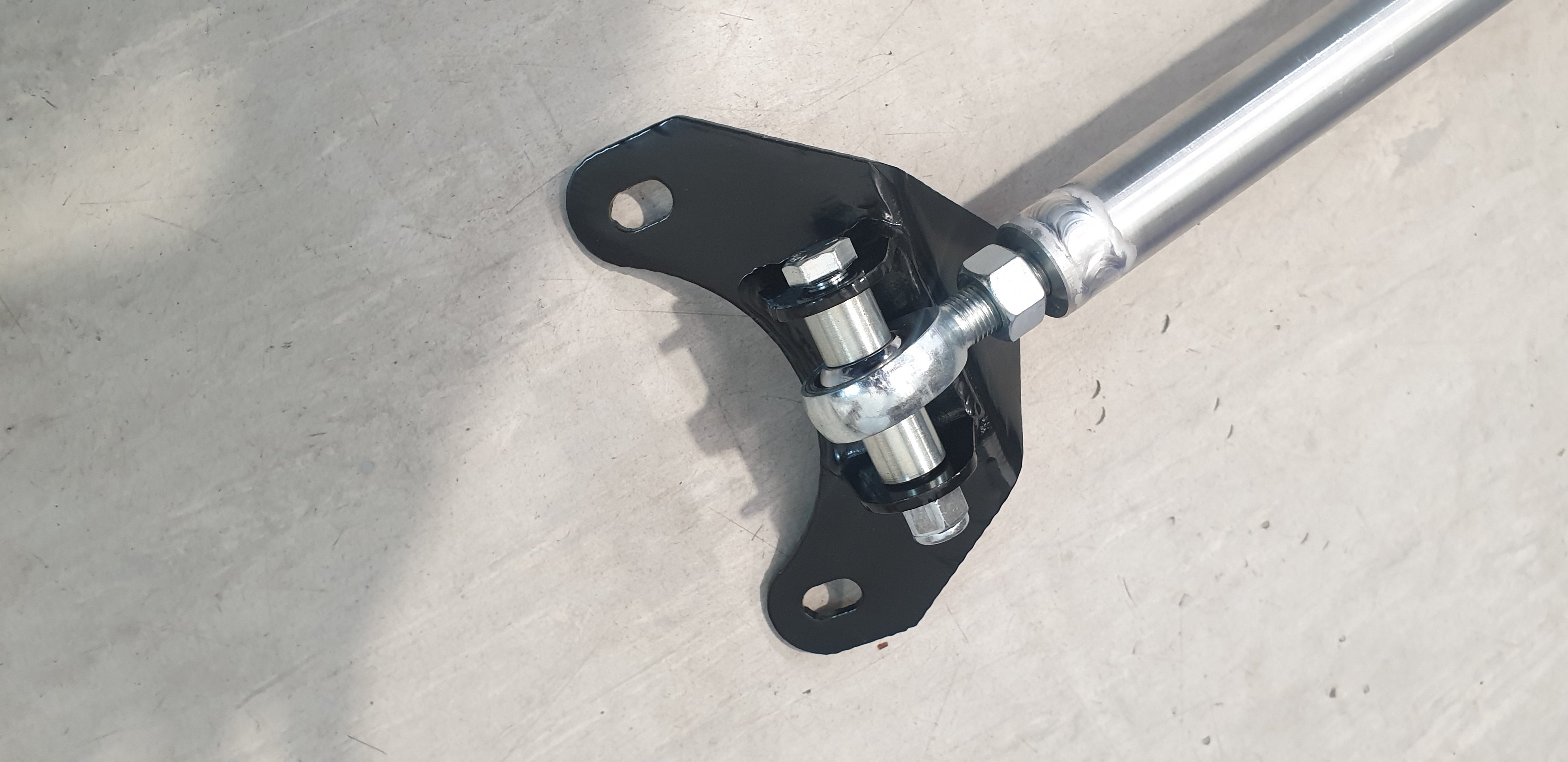
When I was picking up the aluminium bits from @Kimjon he says to me "how are you going to stop them being slippery" I say, "im going to get some skateboard grip tape" and he's like " brb" comes back with a roll. Such a good chap! Grip tape is not on the pegs yet in the images- I wanted to abuse them a bit first with a hammer and with protected legs jumping up and down...it passed He's also just machined up the steel pivot boss thing for my brake pedal. So dreamy.1 point
-
Ummm my friend said he couldnt wait so wanted me to show you this
1 point
-
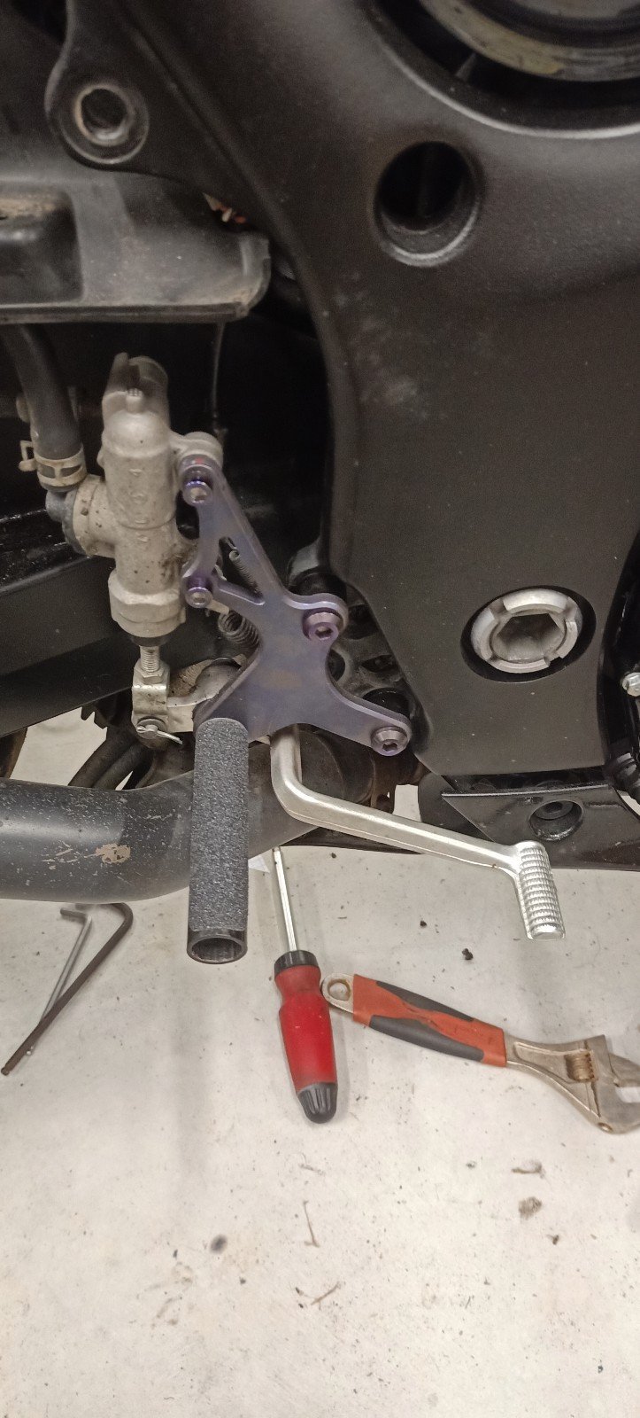
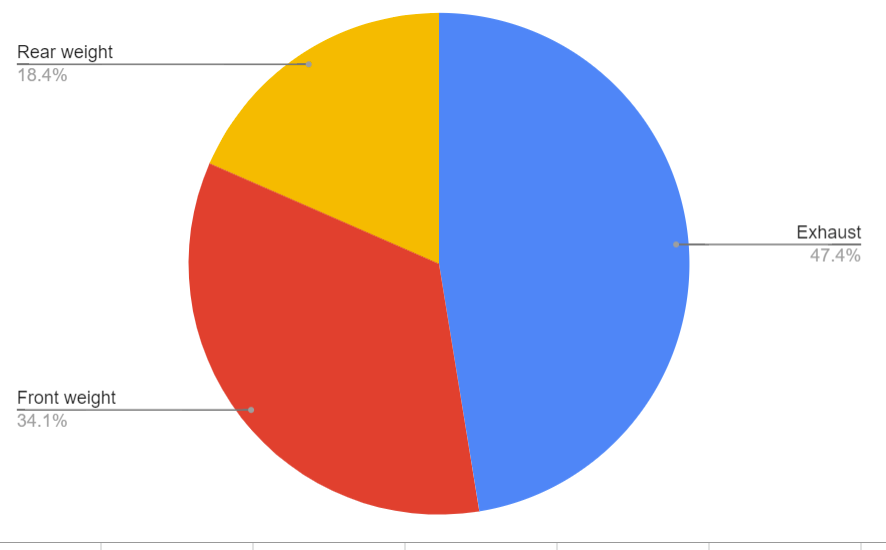
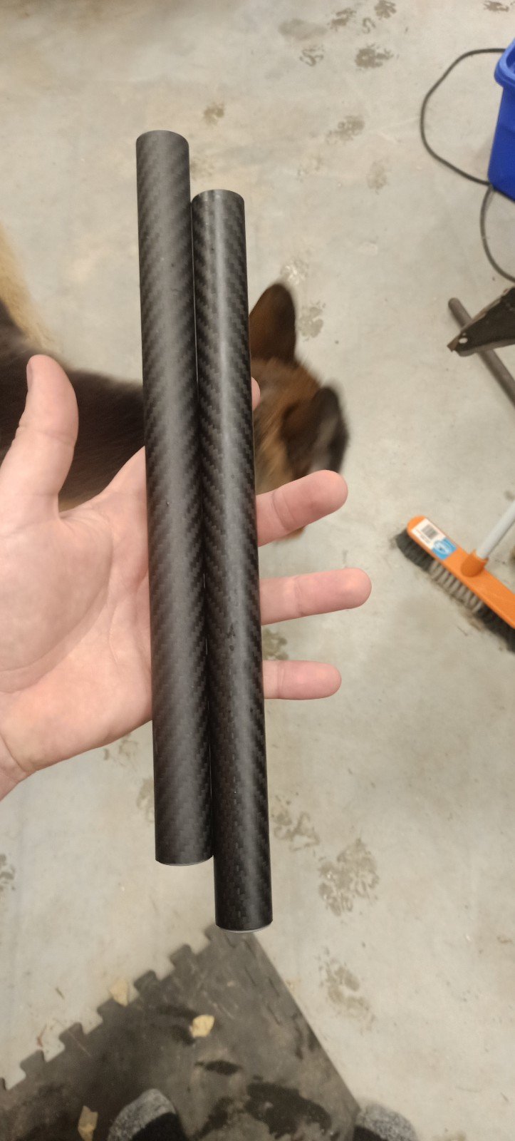
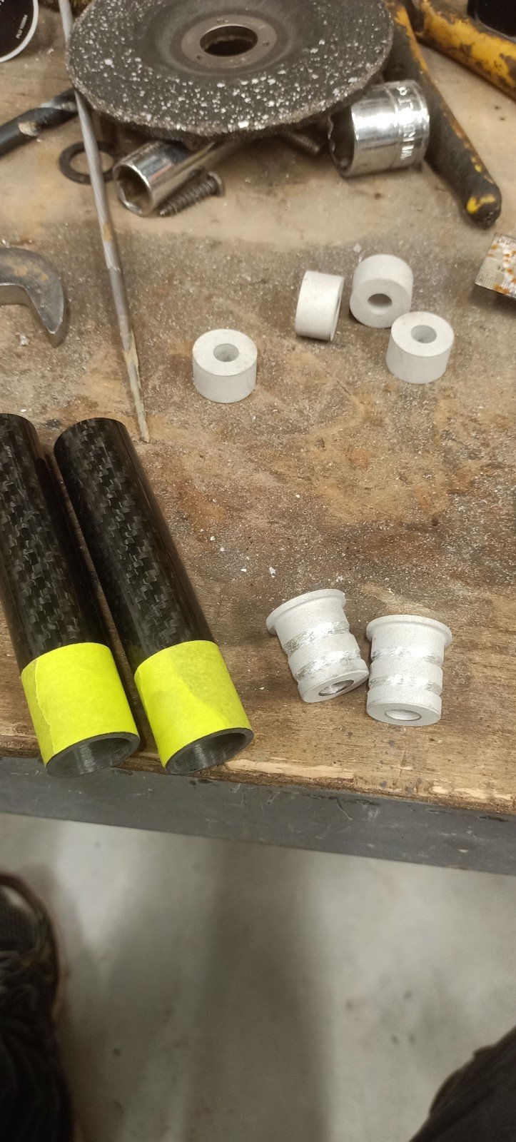
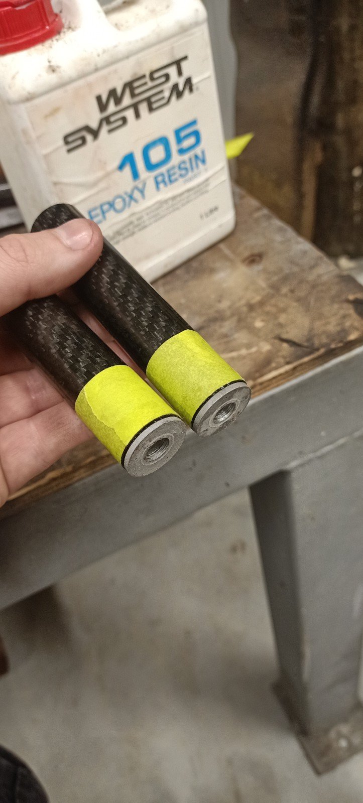
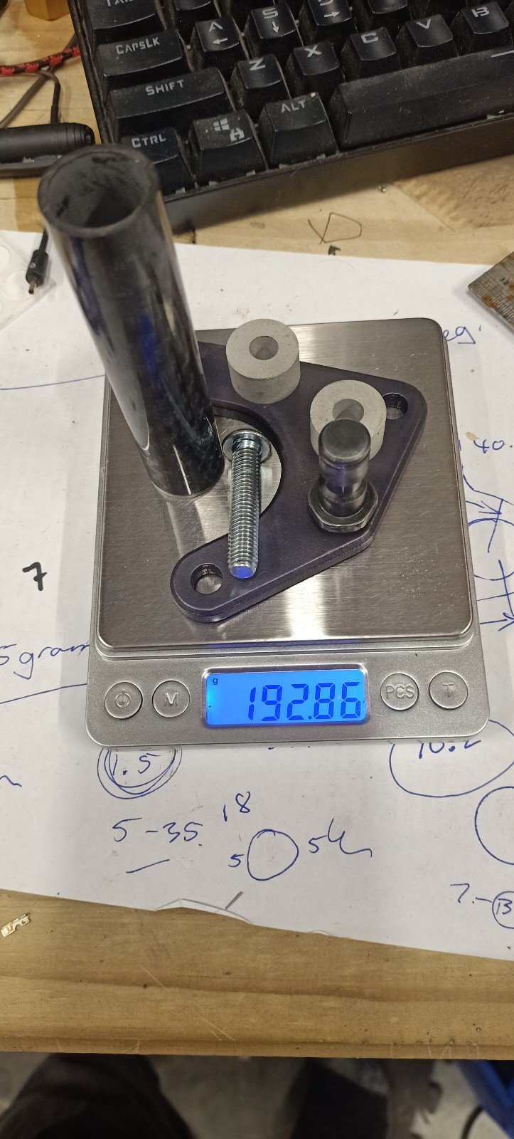
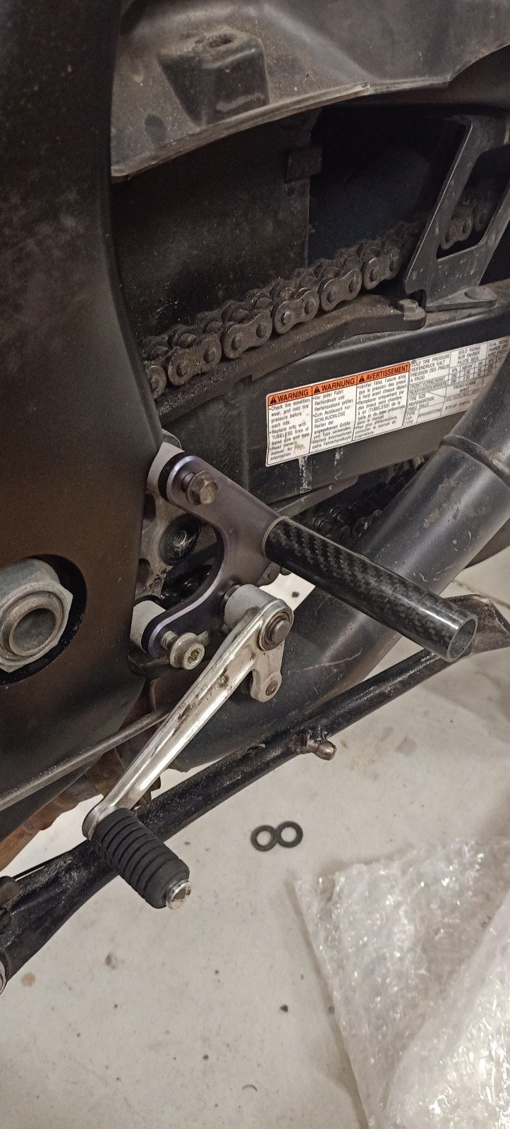
Left hand side peg assembly nearly complete. Carbon bars Titanium bolts Iv got some assembly to do once some fasteners etc arrive but on track to a 20kg reduction vs stock weight. Enough to be felt! Once assembled that will likely be the end of this project because any more weight removed becomes fairly expensive...unless I can be bothered trying to mold some fairings. Edit. Just spotted, total is already 333g too optimistic as have counted front weights twice.
1 point
-
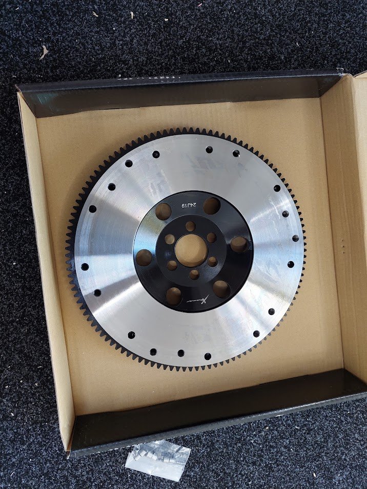
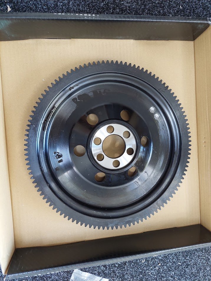
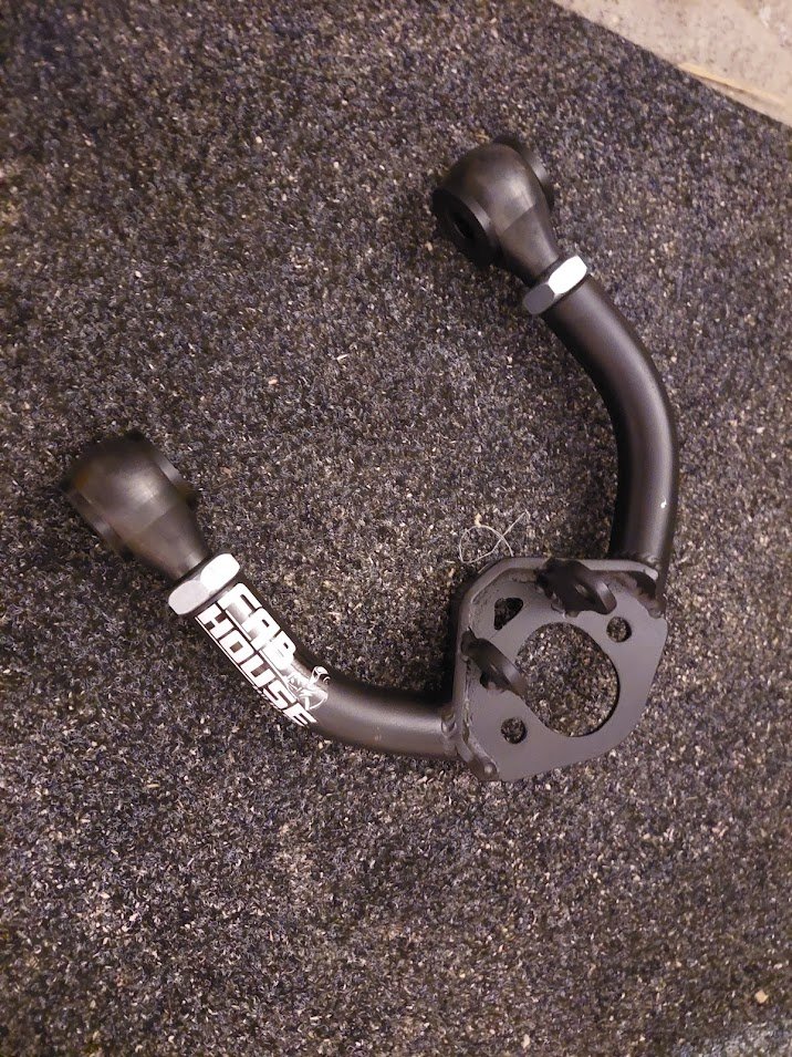
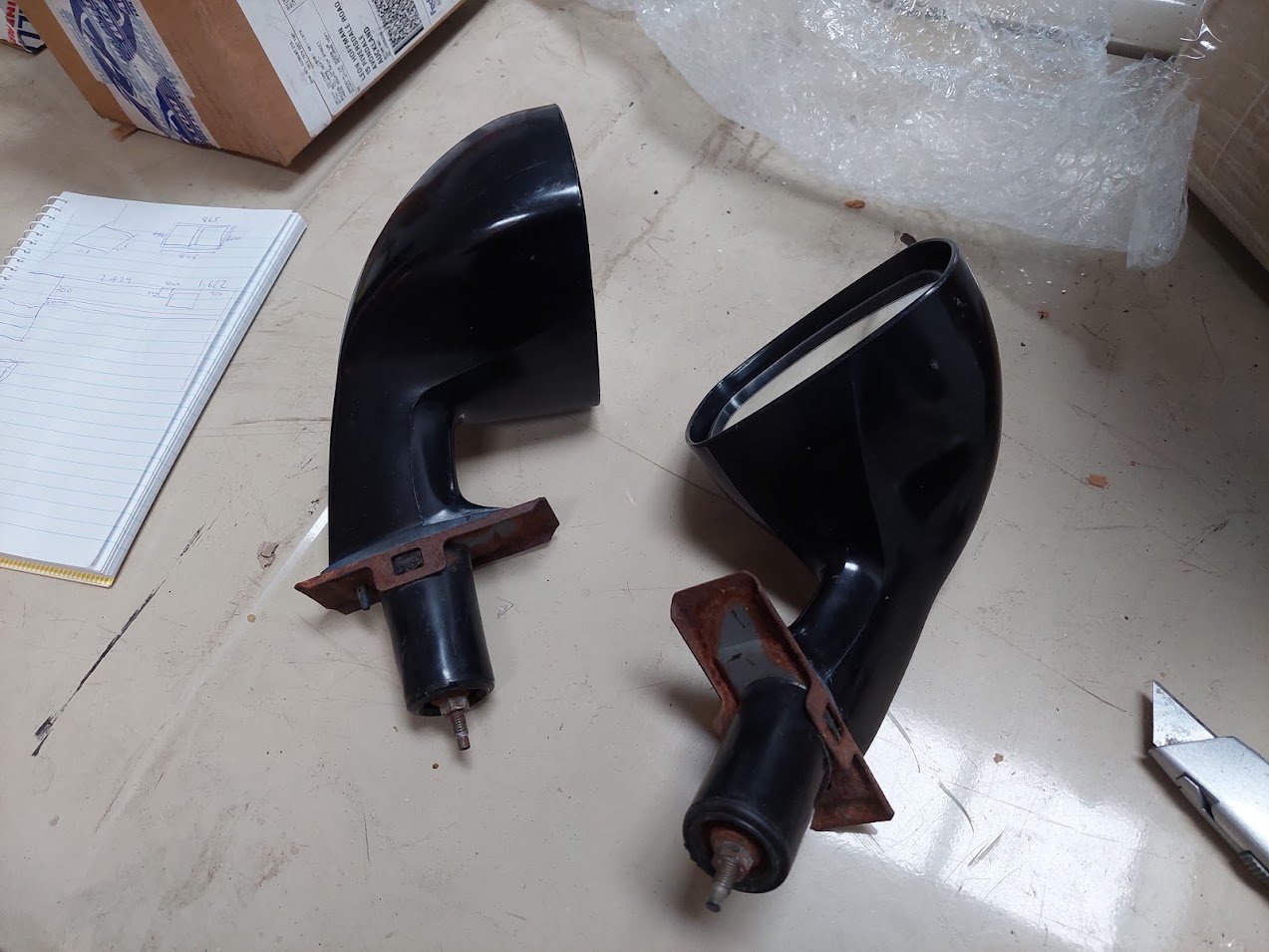
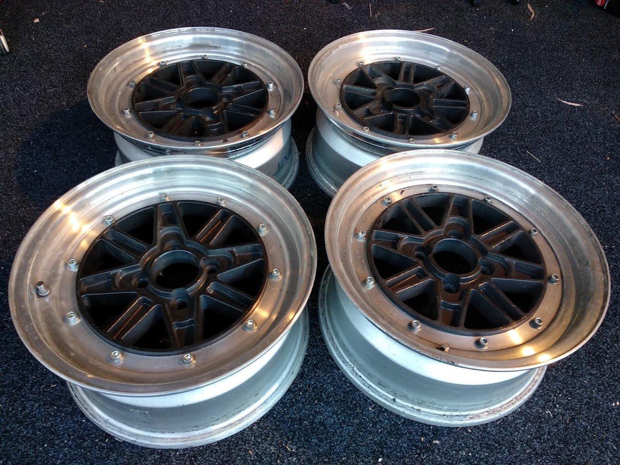
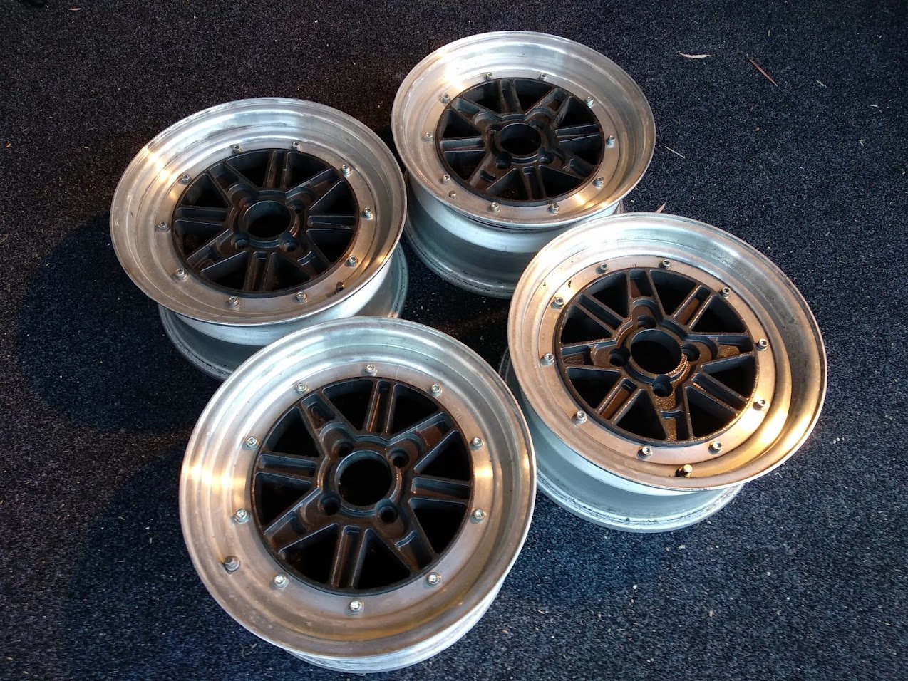
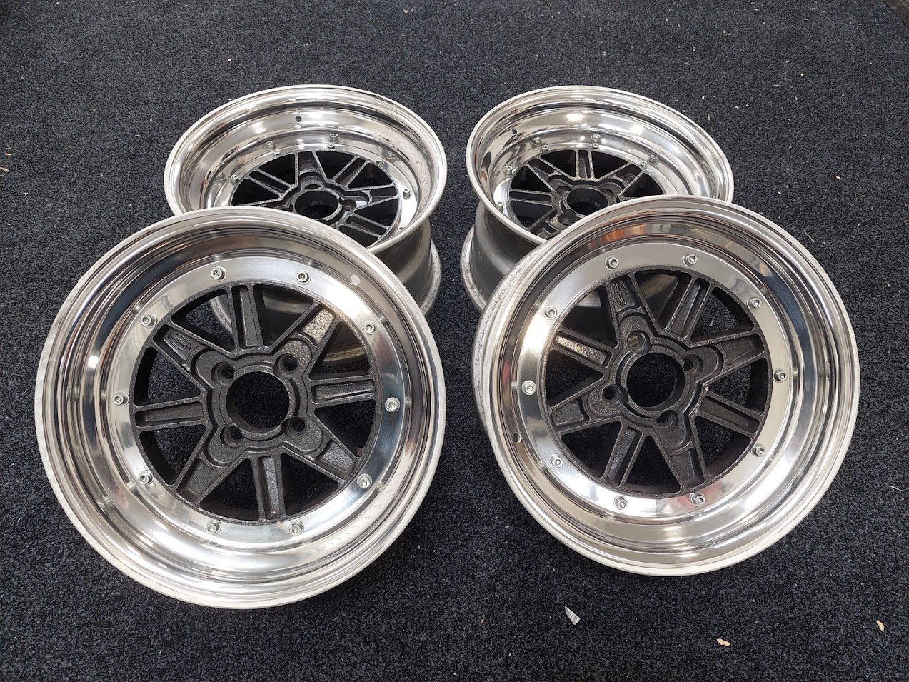
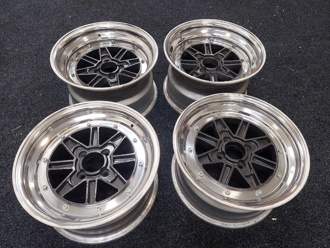
A few more additions to my reckless spending that may or may not be necessary. A post popped up on the Gemini Owners Facebook Group with a guy selling new, billet lightened flywheels for G200Z engines. Luckily the 4ZD1 uses the same 6 bolt flywheel (the E1 flywheel is slightly larger and uses an 8 bolt pattern). I jumped on this immediately and had one sent over. It's about 2.5kg lighter than stock and looks great: Next Next, another dude who runs a shop called FabHouse posted up that he was now selling tubular upper arms. The benefit of these is that they have a much larger platform to enable an adjustable ball joint to slide to its maximum camber. They are also adjustable where they mount to the cross member, meaning that I could pull them in for even more camber if necessary. I am not that clued up on wheel alignment stuff, so I'm not sure how this will also affect the toe in/out. I guess I just have to make sure they are both adjusted to exactly the same point? Bit of a potato-y photo. There are a few things I'm not sure about: the ball joint platform is not knurled and is powdercoated. The joints themselves have knurling on them, so I hope that is enough to stop them moving around. Also, the holes in the platform - the bolt holes and centre - appear to be hand drilled, and not exactly perfectly. They are not terrible but not perfectly round. I hope that none of these things are going to be a problem once it's all bolted up. I certainly hope that this is not going to affect the ability to cert them. Especially because the same shop will be making similar lower arms to enable the use of a coilover spring on a threaded insert, allowing height adjustment. My talks with @cletus have tentatively approved this type of suspension mod, but I guess in the end it will be determined on how well the parts are made. I guess the upside of being in NZ is that the x-member modification to allow the new spring seat to be inserted will need to be welded locally (as I'm not going to send a cross member to Aussie), so can be better watched over. The shop also said that the spring locator is also laser cut, so no hand drilling! Here's hoping. I've also managed to find some factory Isuzu fender mirrors out of Malaysia. Funnily enough, my car actually came with fender mirrors but they weren't cool when I was 18 so I pulled them off. I don't want to think that I got rid of them, but I have a haunting memory of throwing them in the bin. What an idiot. Anyway, I've got these replacement ones that are more proper than the ebay specials I had on there before. They definitely are not perfect so will need some cleaning up and I think I am going to have to 3d print a new mounting plastic part as one is chipped and finding a new one is basically impossible. . For now, last, but most definitely not least - ya'll remember my SSR MkIIIs that I bought off of @mikuni (ex his Piazza - trying finding this stuff in 4x100!) years ago and have had on the car for ever, well, here's them: Anyway, these were going to look way too Aussie drag-spec for my liking when trying to get 225s on them (they are 15x7 ET26). Me and old mate @EURON8 spent many evenings mucking around trying to figure out where I could find some rims that were going to be wide enough to suit the tires. I finally settled on some Minilites after looking around. However there were some issues. The first is that the they only come in 15x8 or 15x9. The cert rules said that 9" wide was out of bounds for a 225 tire. The other thing was that despite it being quite obvious that I was going to have a shorten my diff, the highest offset on the 15x9s, and even the 15x8s, was too low. I would have ended up having to really push my fenders out or run some flares in order to keep the brake calipers inside the wheel wells and from hitting the floor on full compression. It was a similar issue on the front, waaay too low of an offset, even despite the fact that I had decided that I was going to have to run a staggered setup to avoid similar issues on the front. Anyway, after much much mucking around, many nights with measuring tapes, and difficult emotions in leaving the SSRs behind, I decided to change tack. I spoke with my panel beater and he was certain that if the fenders needed to be pulled out, that he could do this without too much disturbance to the stock lines of the car. The one thing I was super anal about was ensuring that the the vertical section on the outside of the wheel arch (does this have a name? I've noticed on modern cars this has got really massive!) needed to stay intact. I am NOT a fan of those rolled up wheel arches which push the vertical section out and into a point, if that makes sense. Pretty common on "stance" and drift cars when they're trying to fit wider rims. Anyway, I digress, with this information from the panel beater I decided that I could go wider on both the front and back (still with a diff shortening) without an issue - I hope! So I boxed up the wheels and went to the post office. Then I waited, and waited and waited. Then these showed up!\ A huge thank you to Aidan at Pine Engineering for adding 0.5" to the fronts and 1.5" to the rears. So now I'm running 15x7.5 ET17 on the front and 15x8.5 ET4 on the rear. I'll be running 205/50 on the front and 225/45s on the rear, which are within a few mm of each other in terms of side wall. I'm so stoked with how these turned out! Annoyingly, perhaps, the tire to wheel width cert rule changed while they were down at Pine! The next step is to mount up the tires - Nankang semis - and see how they fit. Once I've done that I can determine how much diff I need to shorten on the rear, and whether or not I want to muck around with the brake setup on the front to reduce the track which is currently +10mm on each side due to the current brake upgrade. There are options to go back to stock track if I make some changes, but I also want to make sure that the fender pull is relatively even front and rear, so we'll see. The car is still at @EURON8's place and I can't go over because of lockdown. Covid's really wrecking progress here! Anyway, that's the gem update for today. As per usual, click on discuss coupe in my signature to let me know what you think. I'm keen to chat! Extra pics:
1 point


This leaderboard is set to Auckland/GMT+12:00