
Leaderboard


Popular Content
Showing content with the highest reputation on 09/30/21 in all areas
-
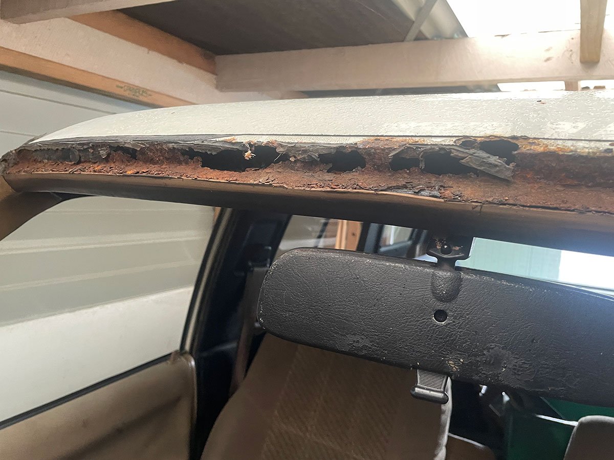
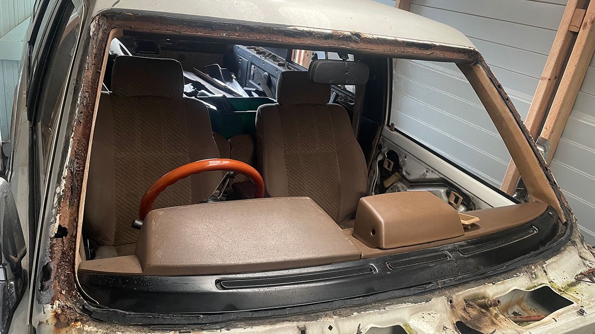
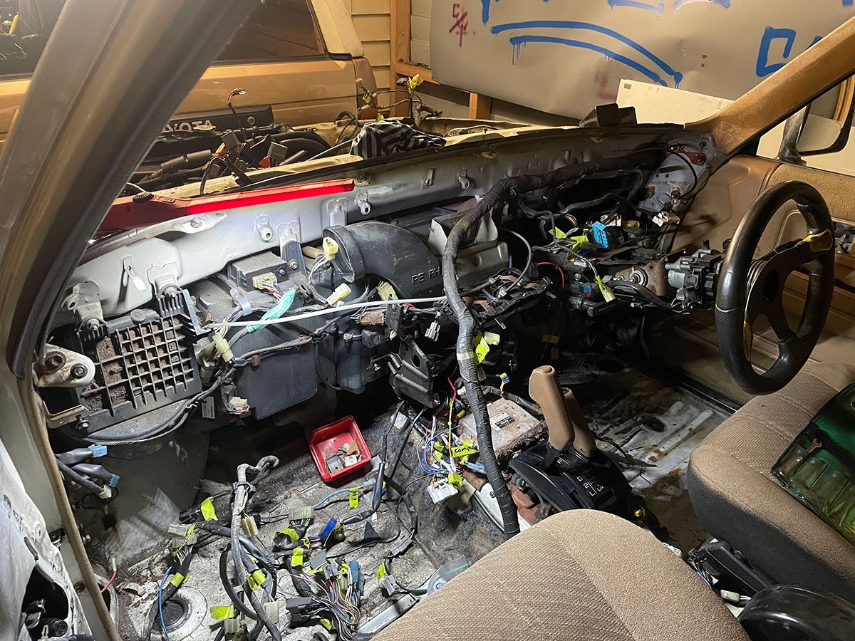
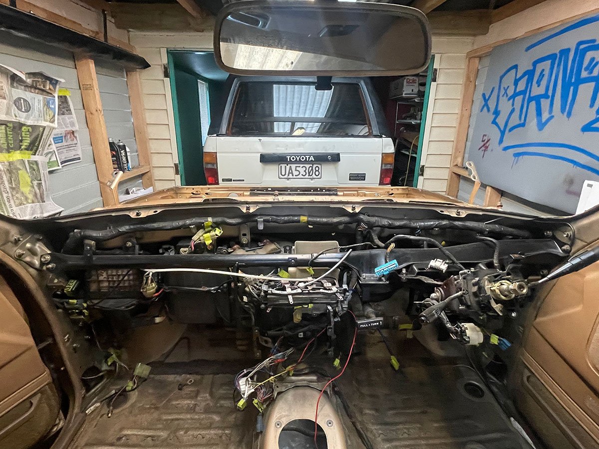
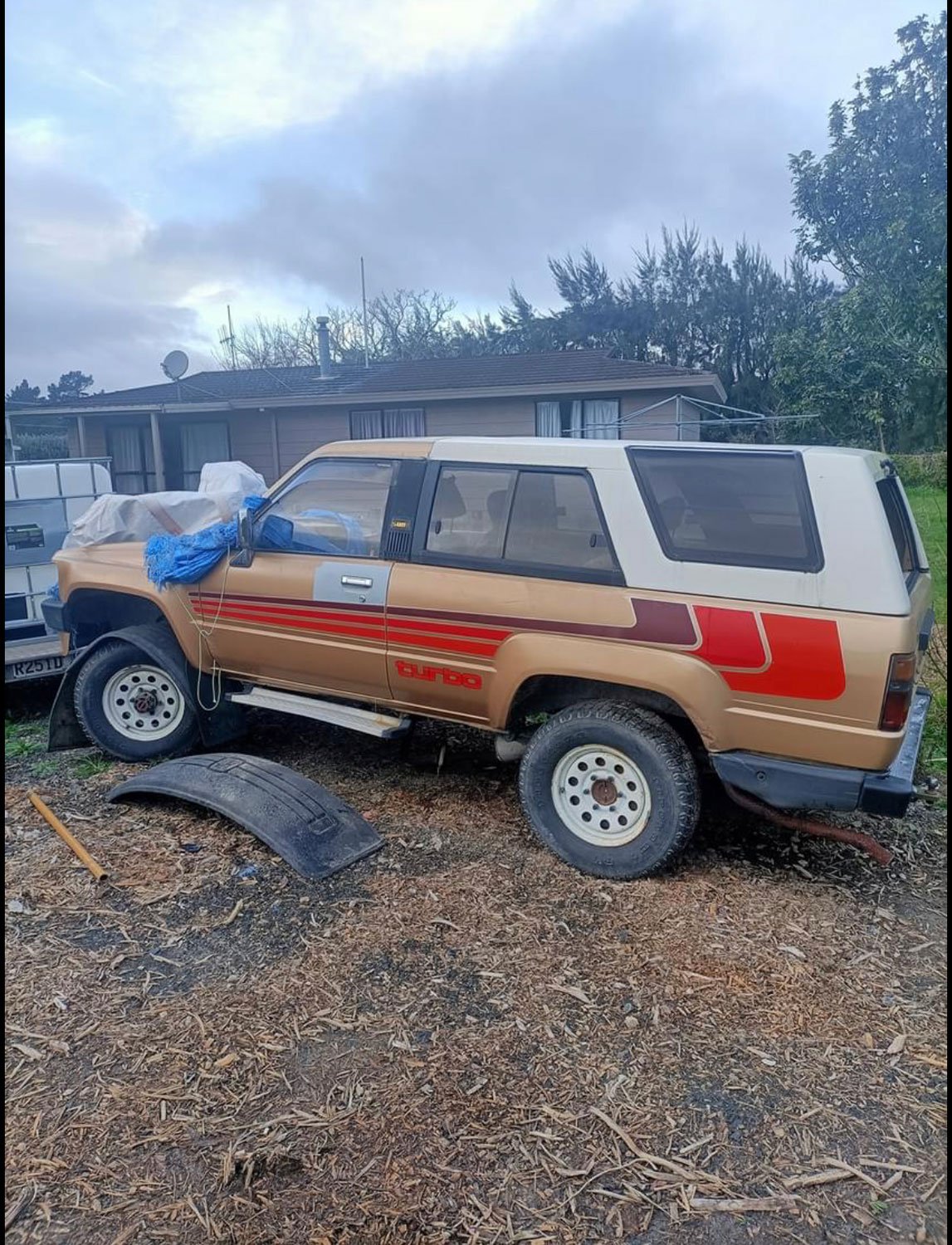
Had the front windscreen removed to make it easier to remove the loom and also because it needs to go into the gold body. She isn't pretty haha Then proceeded to remove loom and install into the gold body. Glad thats out of the way. So far there's 3 plugs that are different between the looms... The door light switches and the loom to the rear (tailgate, lights etc) nothing to major, hopefully thats all.
 9 points
 -
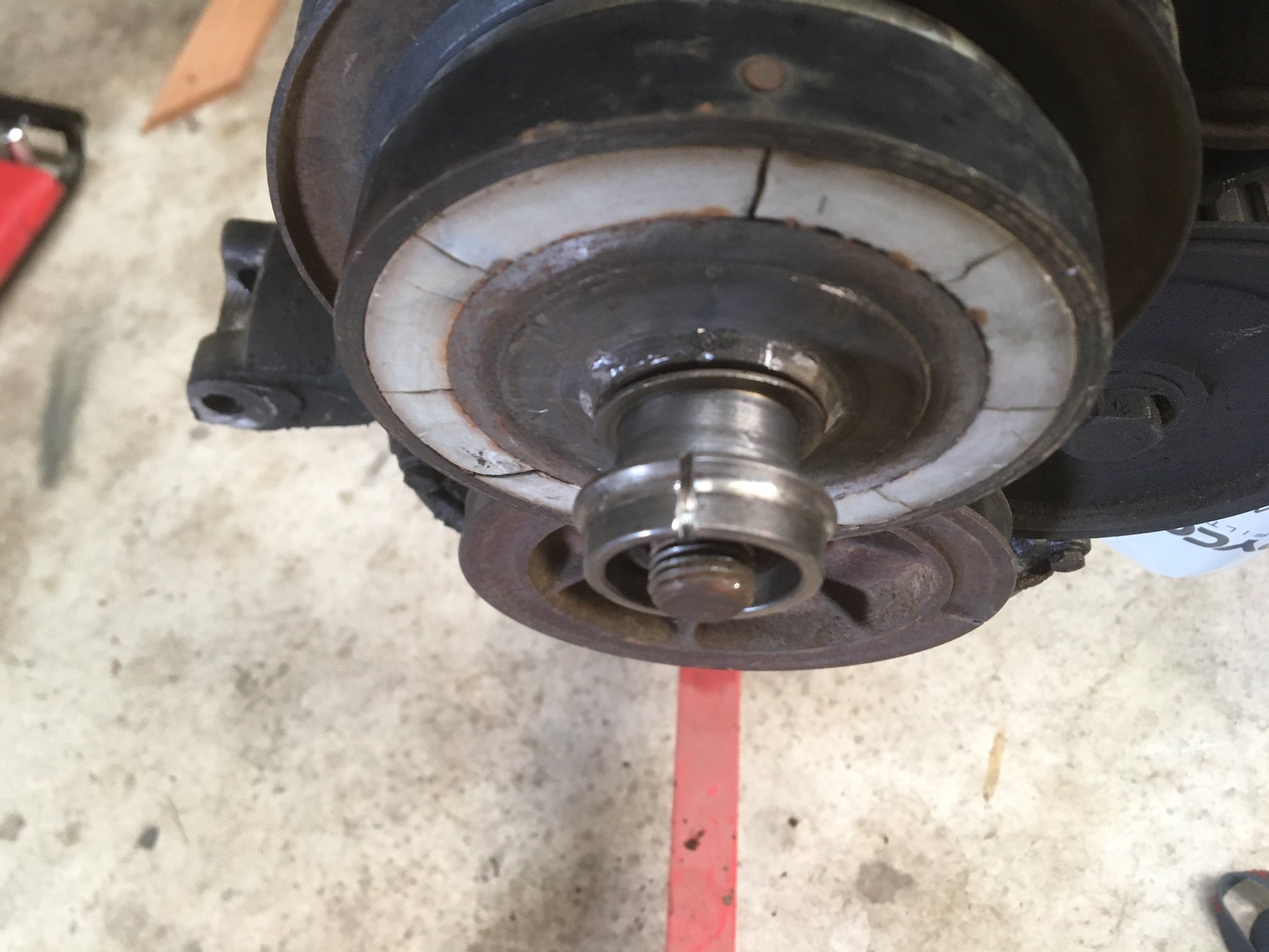
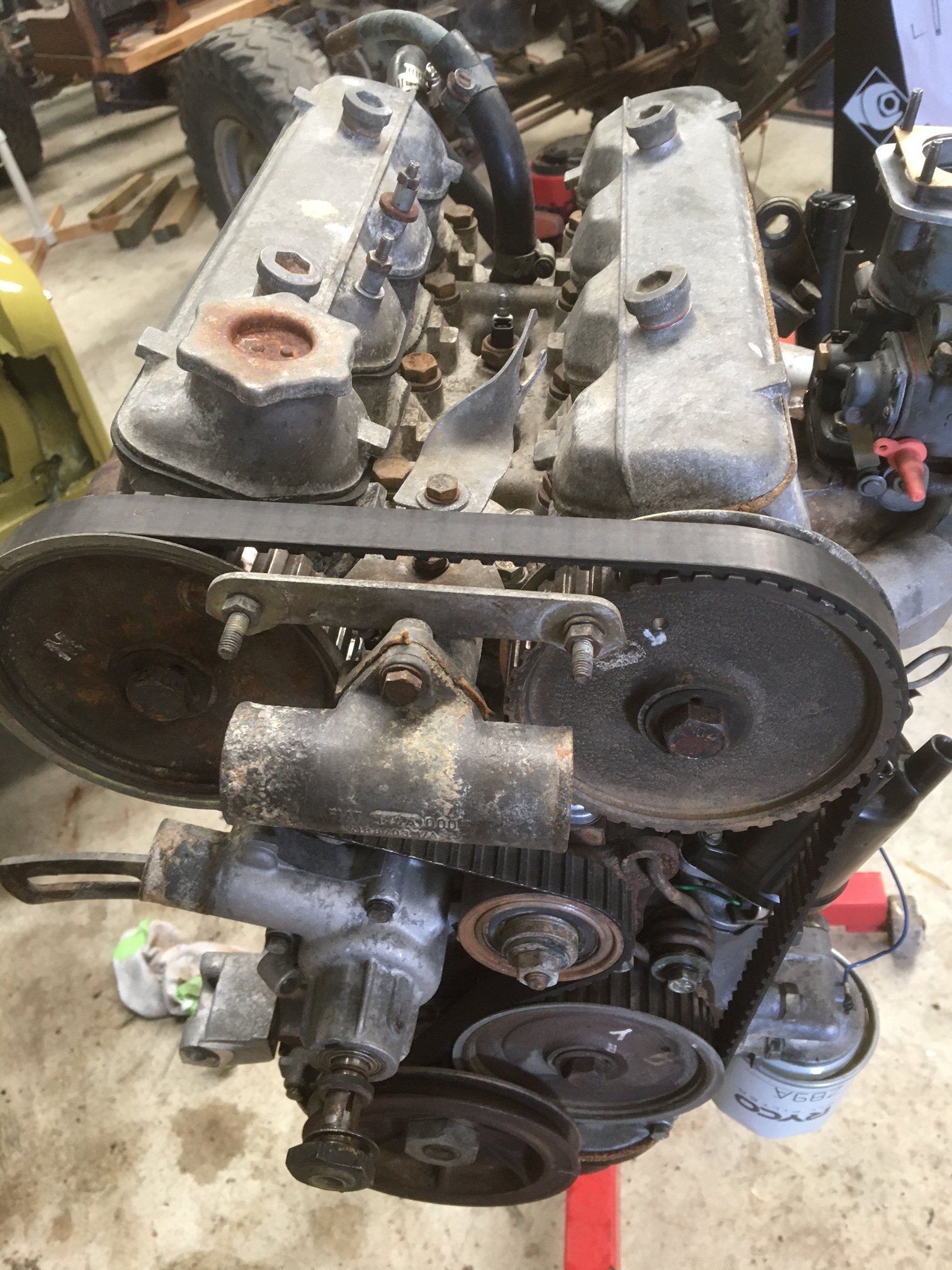
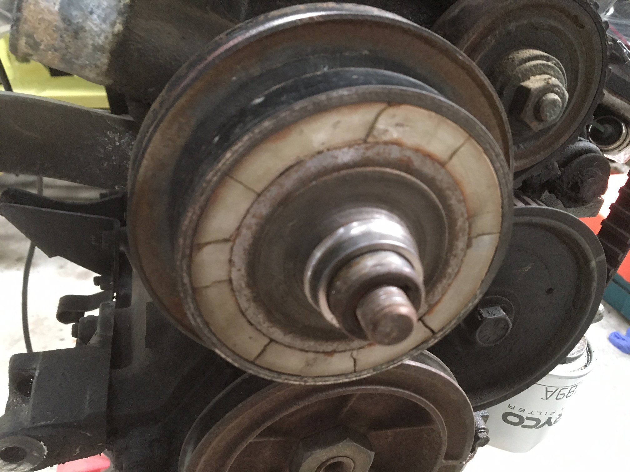
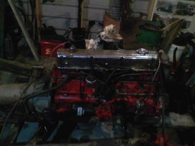
I had to cut the bearing race that was stuck to the water pump shaft. It was still hard work getting the pulley off the shaft and when it finally popped it’s obvious why. Rust! There was also something funky going on with the key. I popped the key out, cleaned the shaft and the bore of the pulley and slid it back on and what do you know…perfect alignment. The water pump feels ok, in fact it looks like a replacement, reinforced by the traces of silicone type sealer residue around the mounting face. It looks like what happened is a ham-fisted amateur, after replacing the water pump (with silicone gasket maker?!) got the key jammed on an angle which prevented the pulley from sliding all the way home and then just did the nut up gudntight anyway. This does not help the fact that the pulley itself is warped and has some crazy runout. Since the fan clutch is junk, and the pulley is riveted to the clutch I wonder if I need to get a water pump and pulley from a twin cam that doesn’t use a fan clutch like the 125. Anyway I thought it was time to clean the motor. I am planning on replacing all the seals and gaskets (not the head gasket because it’s not broken) and I hate working on filthy stuff. I can confirm being able to waterblast the engine upside down on the engine stand is great! I was shocked at how quickly the block flash rusted and also the alloy went powdery really quickly (within minutes) Clean motor:
8 points
-
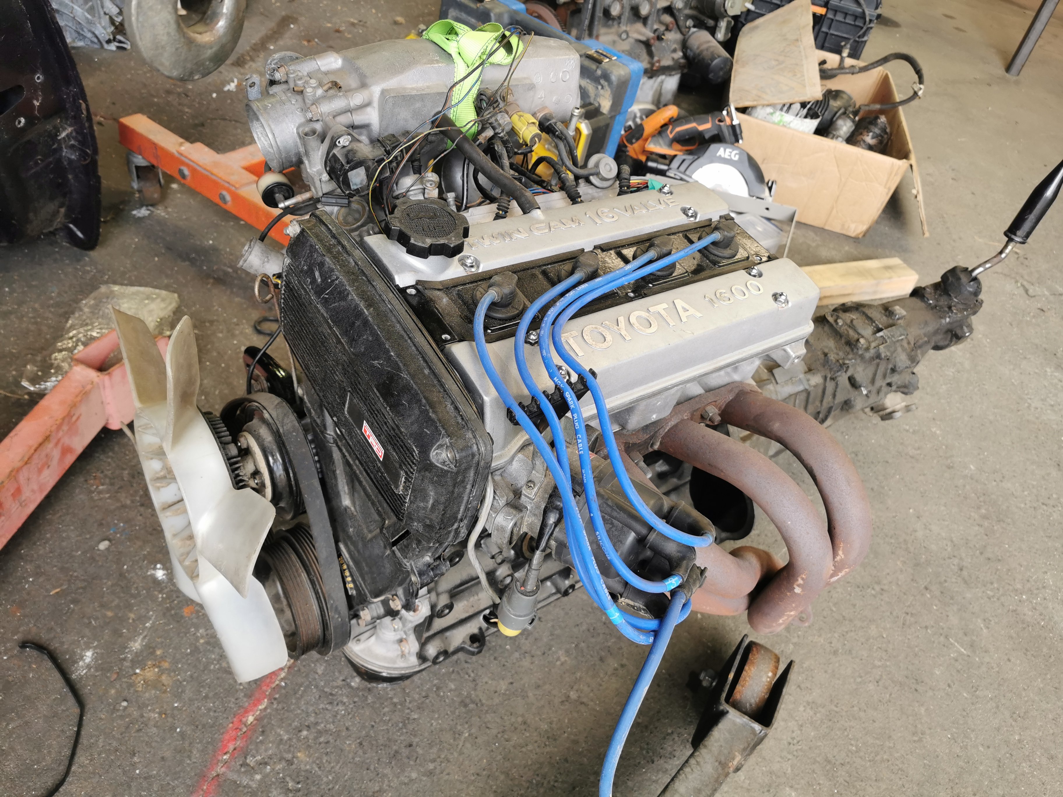
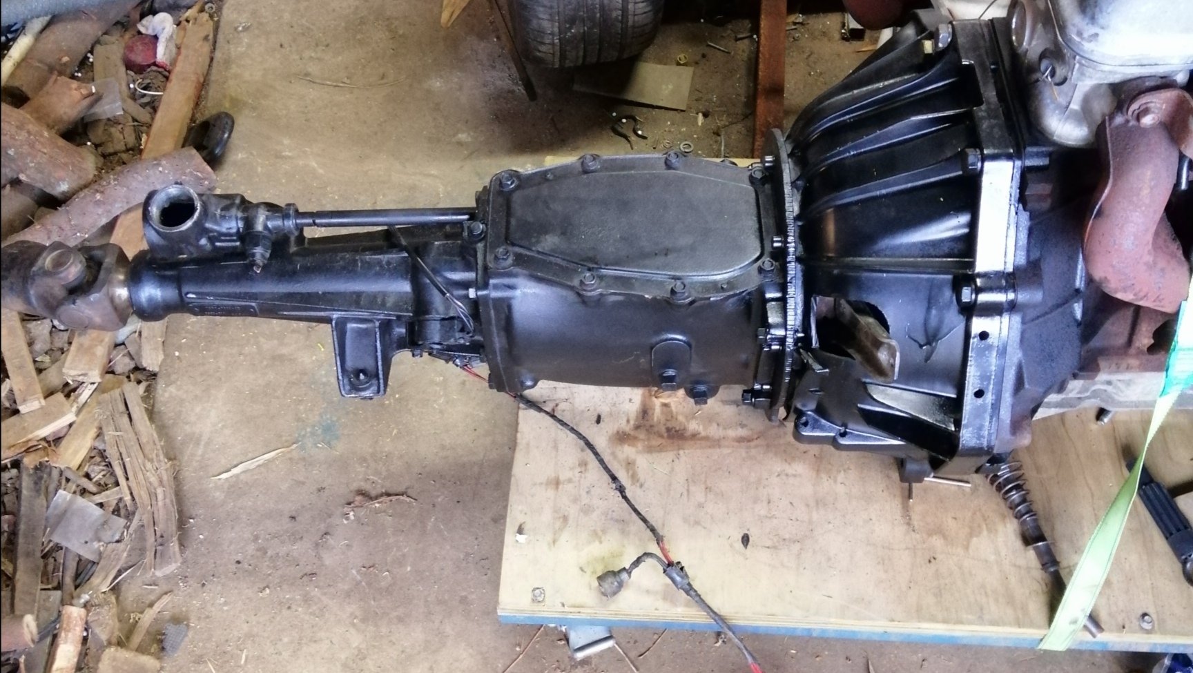
Oops, forgot to load up the engine details. So moving on from the 12a idea, I managed to snag up a rebuilt AE86 4age, stock spec (GER build). Then luckily got a complete T50 box for $500 which is unheard of these days. So I have a loom with it but it's a bit frightening to look at. I used to know someone that could do a loom conversion to have it set up as a 3 wire plug and play.. Contact details lost unfortunately. From what can tell, I will require the following : Clutch slave Yoke Clutch kit Engine mounts Loom work Speedo cable I have considered running it on carbs for simplicity. The cert tags cover a 4agze and T50. Should be a smarter option than a 12a tbh.
6 points
-
Dragged Hull home from work lockup where its been since March. Collected engine/fuel tanks/fishing gear from storage lockup. Life jackets out of the caravan (at same work lockup). Only thing I can't find is the anchor and rope. Currently impatiently waiting for Savebarn to open to buy rope and a grapple anchor. Workmate has given me an old sand anchor. Ran engine up last night once I remembered how to start it. Electrical check. Battery charged. Assemble anchor setup tonight Bring on next week. Here fishy fishy5 points
-
Right, the wallet hurts, but everything I need to rebuild the box is on the way (except a replacement diff, fingers crossed I don't need one). New bearings (steel cage where possible), seals, bolts, clutch, everything. Then once the box is done, I can start fixing the other issues with the car...5 points
-
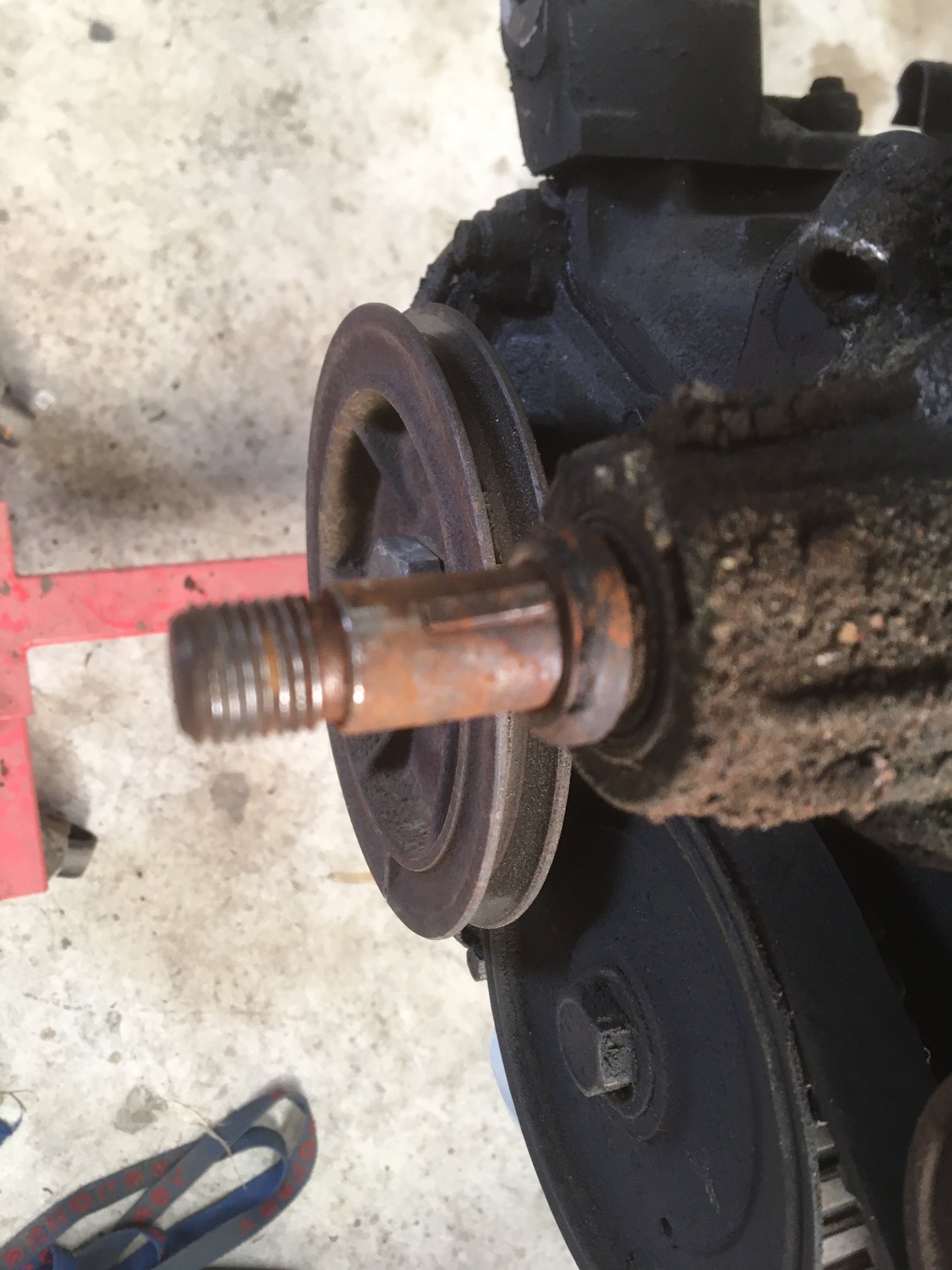
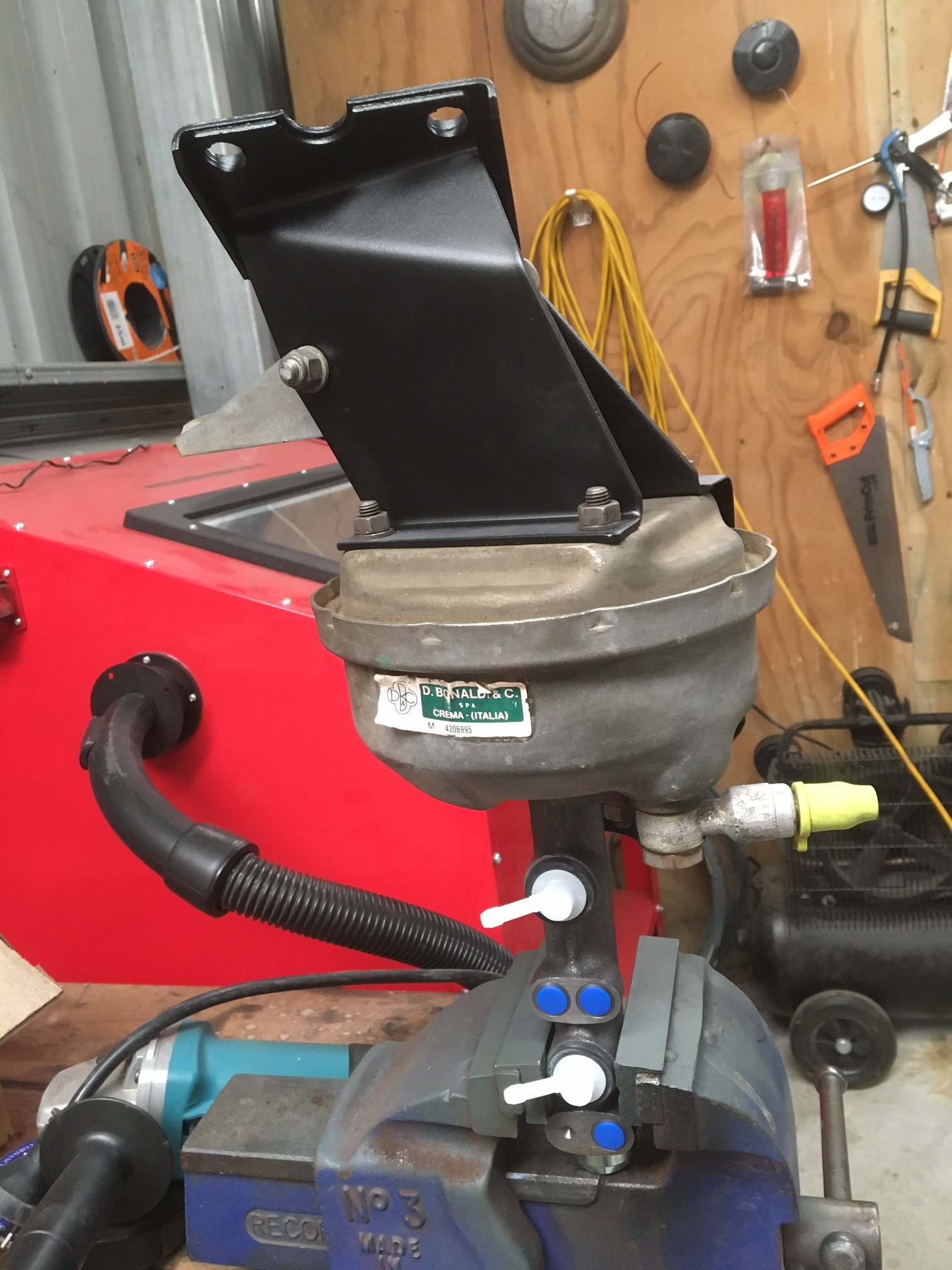
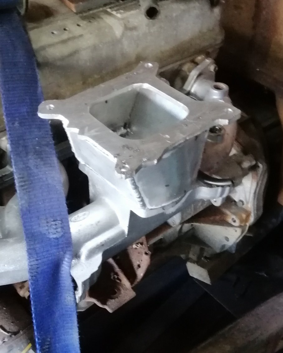
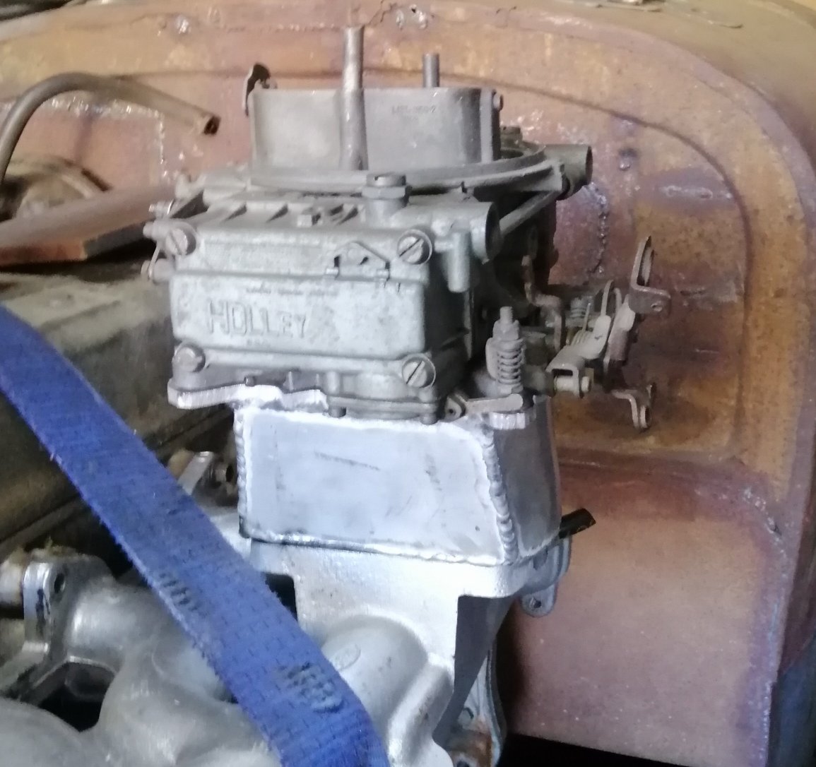
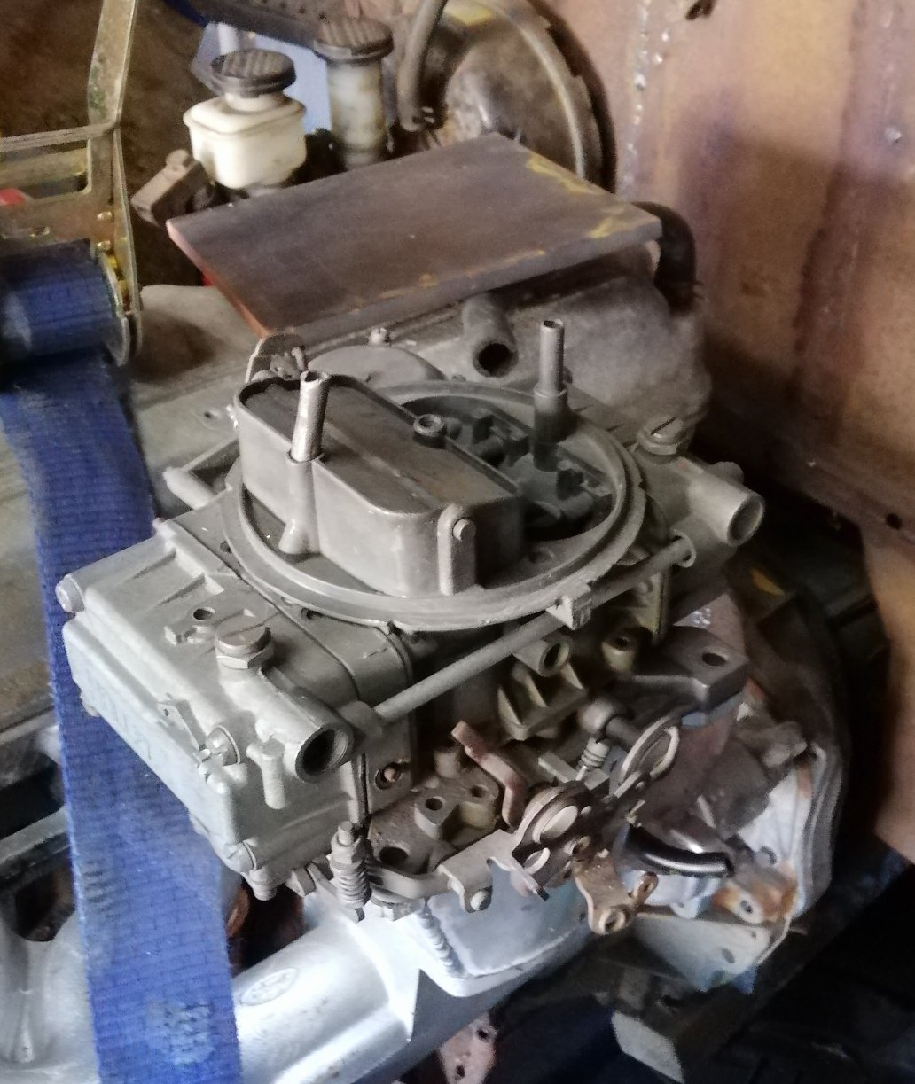
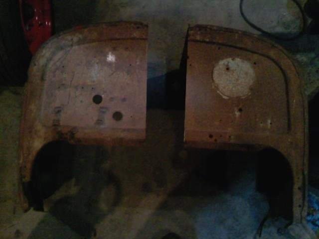
So what I actually did because I’m impatient, is mixed up some paint and brushed it on. It’s covered by the brake booster/mc bracket and it actually didn’t come out that gross. My attention now turns to the engine. I pulled the alternator off and then I wanted to pull the fan clutch off. Unfortunately, only half of it let go. Side A: Side B: I have another moderately annoying problem. The water pump pulley is bent AND it’s half a pulley width out of alignment with the crank and alternator pulleys. More will be revealed when I get the rest of that fan clutch off, I suppose. Anyway, the brake booster et al is ready to go back on the firewall when the time comes.
4 points
-
There shouldnt be any hate, that shit is cool. I have been pondering EV converting my townace ute for my next major project. Here is one i looked at a wee while ago, boy has done a super nice job.3 points
-
I've helped complete an EV in Australia and looked into it seriously in NZ. Whilst there are a few turn key companies in NZ that will help you out, you're on a hiding to nothing trying to get anything remotely cost effective out of them for the DIYer. You can look at importing from AU or USA but then you'll get stung at the border for whatever they feel like charging you that day as well as no easy warranty option. I'm still looking at another EV conversion but doing it for a vintage tractor. I can keep the volts low and use older DC forklift technology. Plus having battery weight in a tractor is good for me. To do a car in NZ either you need to look at getting a written off leaf and get chopping, or for a bespoke option with decent power and range you'll be closer to 100k than 50k.2 points
-
forgot to post these. first is R32 GTR intercooler core design. second is plazmaman core. 2021-09-28_06-56-17 by sheepers, on Flickr 2021-09-28_06-56-26 by sheepers, on Flickr2 points
-
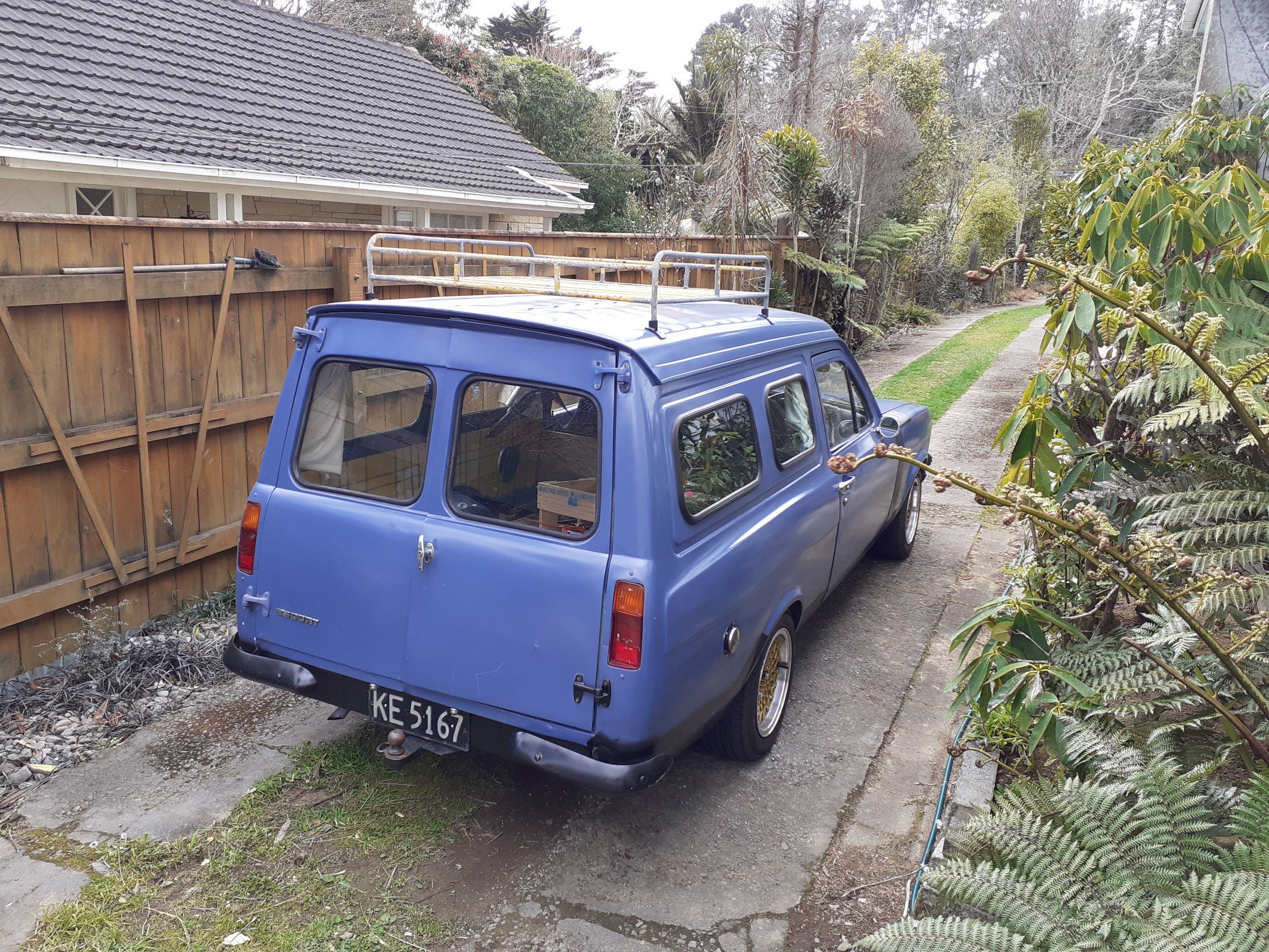
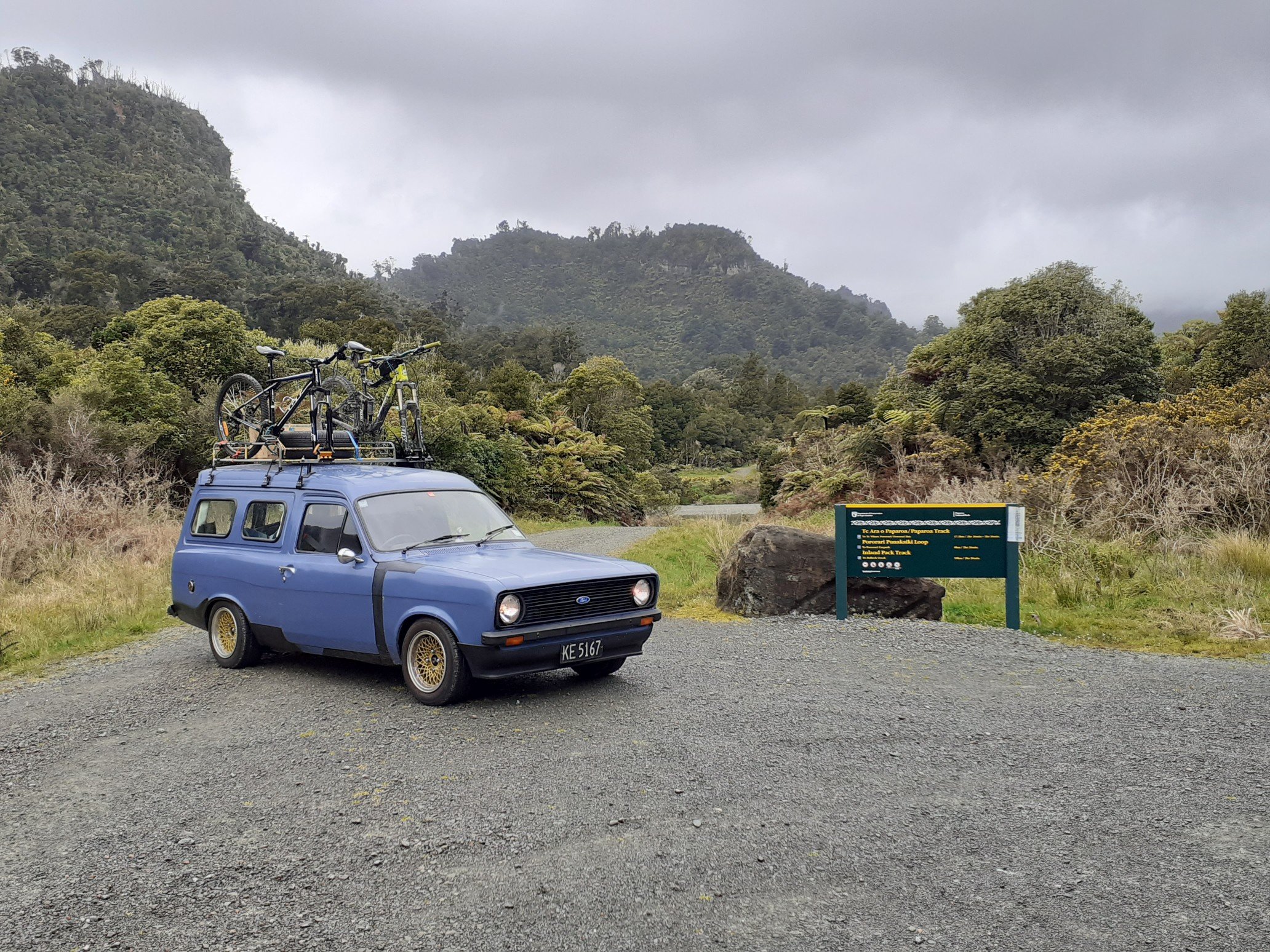
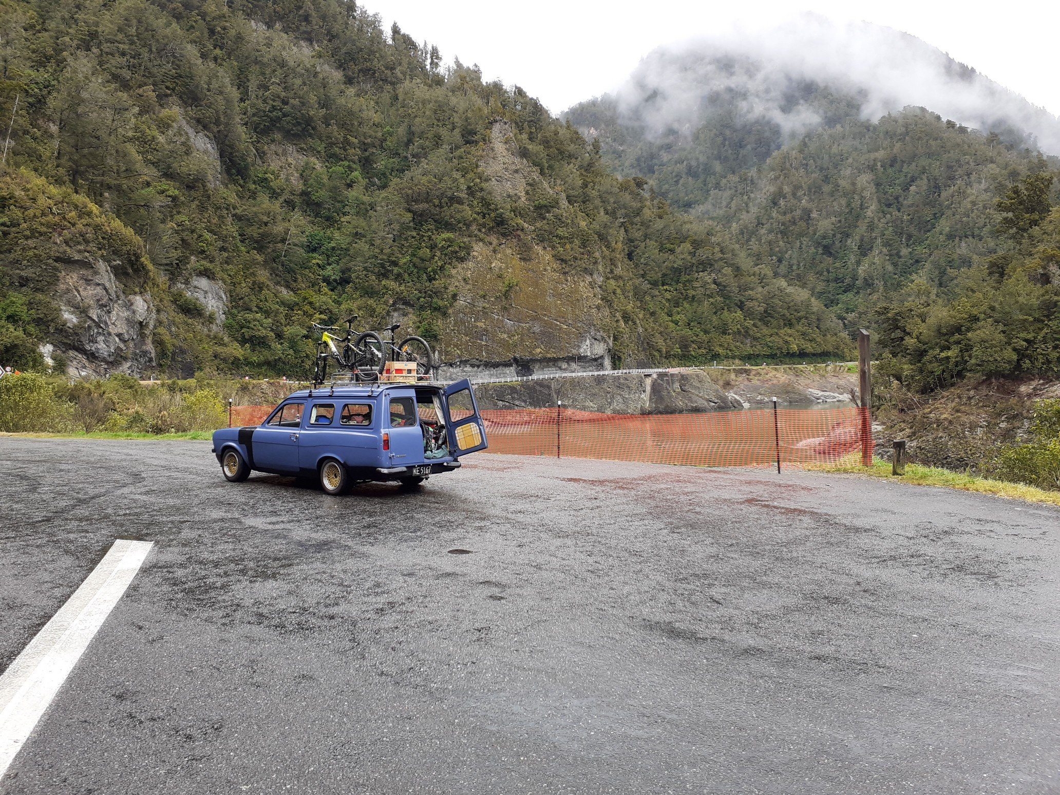
I put the bike carbs back on and ran it up to the palmy swapmeet but on the way back it developed a strange misfire/stutter at constant throttle. I checked a few things before admitting defeat and putting the standard carb on again. I took it all apart and gave it a good clean with a diy ultra sonic cleaner but the stutter was ever present but not as bad? I didn't have time to investigate it too much as I had a roadtrip booked with it down to the west coast for a bike ride. I wanted to mount my bike on the roof for a couple reasons. It would free up all the space in the back, plus it meant I wouldn't have to worry about dragging all the mud and crap in. Using a tow bar bike rack is OK but meant I would have to take the bike and rack off everything I needed to get into the rear. I couldn't find anything suitable for the roof so I was determined to make my own. A visit to grandad one day and he casually mentions his old roof rack is in his shed at home and had been for 40 odd years. A quick look in the exact spot and what do you know. Grandad had this rack years ago on his mk1 zephyr. Under all the new paint, there's the zephyr green which he painted to match. Fitted it up to to van and it was perfect. I made new feet and gutter mounts out of old folder dividers from a file cabinet (not pictured) to mount it. The rack was too short to fit my bike in so I made a front bar out of an old rusty piece of angle iron and used some tubing from an old exercycle to make a dummy axle to mount the forks too. Perfect for the parts bin van. The 1,300km west coast trip went well. The roof rack survived, even when I forgot about the bikes and took a branch off. Luckily it was at low speed and the tree was mostly dead. I lost one alternator bolt, a second came loose, front left suspension has decided to start knocking, discovered a couple of leaks under the dash and with all our gear we were riding bump stops some of the way. Success.
2 points
-
Buy 2 and put another motor in the back2 points
-
I've been researching it for ages, but like Cletus said, until the costs come down it's a bit of a pipedream - because it is pretty much a besoke job for every car it's going to stay costly unless you can find some modularity sort of thing, then costs might come down. For example EV West in the states do a lot of VW/Porsche repowers and released a bolt in SBC engine conversion last year. But still at the spendy end, and every car is going to need a bespoke battery set up. Unless we just creative commons the designs... https://www.autoblog.com/2020/10/02/ev-west-tesla-motor-conversion-chevy-ls-sbc-mount/2 points
-
Neat car but I think for conversions like that to become popular, the price of ev parts will have to come down a lot. 100kw, granted it would have heaps more torque, but a stock 4age has the same power? And it cost 30k The fact it costs less to run isn't really that much of a plus unless you do heaps of kms, as the higher initial build cost would take forever to gain back in fuel savings on a weekend only sort of car2 points
-
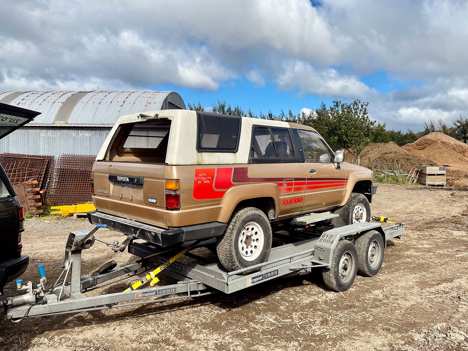
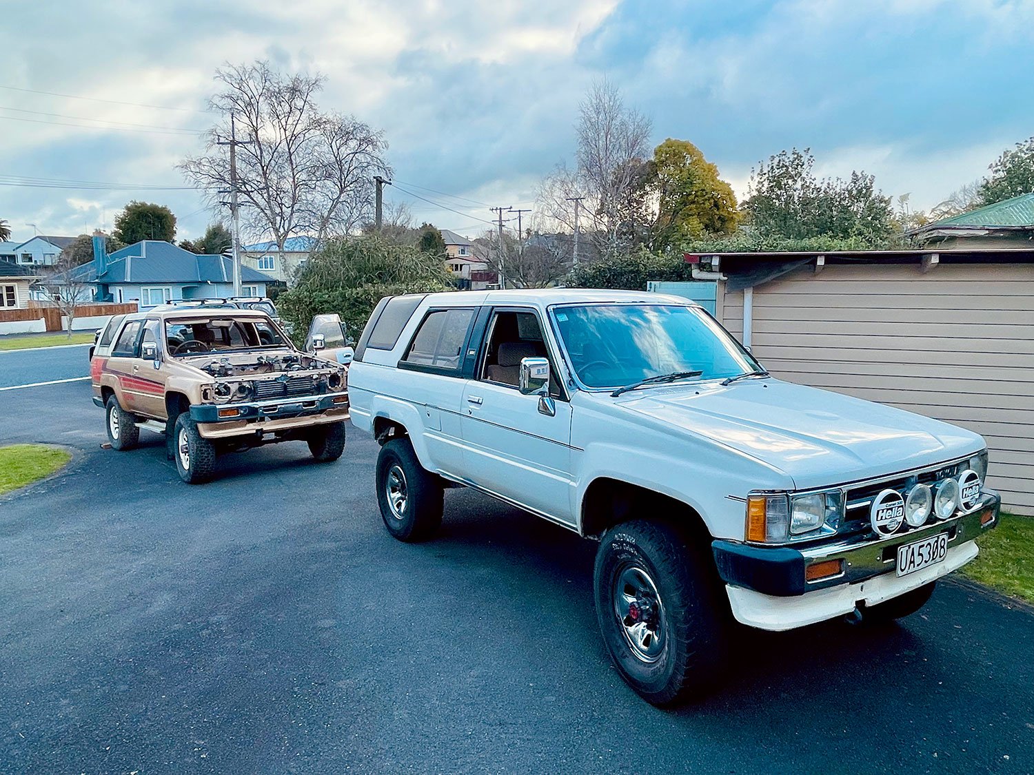
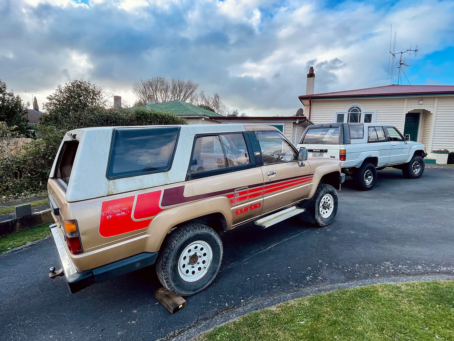
Always keeping watch on Market Place and Trademe for anything to pop up for these and came across this parts truck for a good price. Only 140 kms on the clock and solid. Story is the brakes needed rebuilding so the old boy took it to Pick-a-Part, It was mint apparently. Then the dude I bought it out of Pic-a Part after the running gear and some of the frontend had been taken. He didn't have time to do anything with it. Then along I come and swoop on it real quick. Its mint apart from whats been taken. Perfect for what I need to get mine sorted. This all happened the week before lockdown happened. Good timing really
2 points
-
Don't yell at me but anyone done this or is in the electric car field on here. I saw a mk1 Cortina that had been done last week and shit it was cool.1 point
-
Both keyways (cam and crank) should be at 12 o'clock. From memory. Is that the case?1 point
-
yeah pronounced Hamish1 point
-
Torco do a mtf compatable with honda boxes that's a fair bit cheaper than the genuine fluid. I got some from 1st auto parts(ex segedins) I assume they still stock it1 point
-
Well, that didn't take long. I knew I was on borrowed time with the gearbox but didn't expect it would come around this quickly. So, I had the new tyres fitted yesterday (Yoko AD08r in the correct Turbo size), fiddled with the old brake light switch (since the replacement is AWOL) to stop the brake lights from being on all the time, and then went out to bed the new brakes in. The car was running great, it ran smoothly and was responsive. The brakes have good feel, with no shudder and the gearbox was shifting great. A few hard stops and a KM or two later I pulled over to check the wheel nut torque (not going to take the risk of not checking them after a brake job again, after the wheels nearly coming off on the Corolla). Of course, the wheels were fine, so I pull back onto the road, gave it a bit of throttle, the turbo spins up, boost comes in and then suddenly It just free revs. It felt like it popped out of gear, so I clutch in, into neutral, into second, let the clutch out, and nothing, just revs. Oh no. I roll to a stop at the side of the road and try a few more gears, nothing, I can let the clutch out with it in gear and nothing happens, doesn't even stall. I can push the car forward when it's in reverse, which is not good. I fire off a quick text to let my Wife know I might be a while and call AA to arrange a tow. "Yes, I am about 1.6KM away from home" I confirm with the rep on the phone... At least it looks good, sitting there, waiting. Whilst I waited I took a quick walk back to where I stopped to check the wheel torque A quick sniff test confirmed that was a nice trail of my fresh, rather expensive, Honda MTF gear oil. There was also a small amount under the car where it sat. After a fairly short wait, a friendly chap with a truck arrived winched the old girl aboard and dropped me home again. The Tomcat repaid his help by leaving a large amount of gear oil on the truck bed, and on the road where the car was loaded and unloaded. So what went wrong then? I jacked the front of the car up, confirmed it had no drive to the wheels and slid under to find out why. That'll do it. The shiny bit the arrow is pointing to should be inside the gearbox and shouldn't be visible. It also explains why the gearbox weed everywhere as the seal was wide open without the shaft to seal it. I did some careful levering with a prybar and popped it back into place. I'd be very surprised if this is a new issue... I suspect I'm not the first one to lever that back into the gearbox. Whilst under there I had a good look around. Noticed a couple of minor coolant leaks I will need to attend to, but also noticed this rear engine mount completely missing its nut. I found a new pre-loved nyloc nut that fit, and wound that on nice and tight. Who knows, maybe that will fix some of the movement in the engine. The driveshaft has quite a lot of radial (up and down) play when inserted back into the gearbox, which confirms my suspicions, both about the condition of the box, and why it popped out; the gearbox bearings are stuffed. These gearboxes do not tolerate being neglected, and being over a litre of oil down when I got it, I suspect it's not had a good time. When Rover had these boxes built, they chose to use hi-tech ball bearings with plastic to retain the balls. This probably seemed like a good idea at the time, and they worked well for years, as long as the plastic didn't get old and the gear oil could keep them cool Above is an example of the bearings used in the PG1 gearbox; uprated steel cage bearing on the left and stock plastic cage on the top right. Unfortunately, the bearings Rover used seem to wear badly no matter what (they tend to get pitting in the races and go a bit grindy), but when coupled with low oil and high temps, the plastic can fail, causing the bearings to no longer be sufficiently retained, as per this extreme example where the plastic has broken and the balls have all converged on the lowest point. This sort of damage is what can also break the flange off the diff center. So I suspect mine has either started to break down the plastic, or the races have worn to the point there is excessive play. The popping out drive shaft is the usual giveaway of bearing failure. With the driveshaft back in place, I have drive to the wheels again, so once I refill the gearbox with the cheapest oil I can get, the car will be mobile enough to get out of the garage and into the drive, where it will sit in shame waiting for me to rebuild the gearbox. I will be stripping the gearbox, replacing all the bearings, and oil seals. Uprated metal caged bearings will be used everywhere they are available. Whilst I'm there I will also be doing the clutch. I'm hoping to keep the Type A torsen diff, but I will need to check it's in good condition once the gearbox is split; if not, I will need to increase the budget and add a Quaife to the list. After that, the gearbox should be damn near bulletproof. I was really hoping to get more than a couple of KM (literally, I've done sub-10KM since I got it) out of the car before it seriously broke, but that's the British car game I play. Every day is a gamble.1 point
-
Not an expert sorry, but I harbour secret thoughts of electrifying my Land Rover one day… I’m not into electric conversions for their own sake, but let’s face it, some cars aren’t about the engine so electricity can make them better. (Don’t hurt me please)1 point
-
Just run a drill and tap down it. Maybe drill slightly oversize so the tap doesn't work too hard1 point
-
Starter motor time. I had bought a Subaru leone 1.8 starter from the fella I'd got the gearboxes and 1.8 ring gear from. Made sense to use all the same bits. Only thing I'd have to do was move the mounting face for the starter forwards towards the engine to suit the new ring gear position on my home made flywheel... Easy as I thought and I had it all planned out. I shall start at dawn! However that's not what happened once I got a friendly query from a fella about the starter motor turning the engine the wrong way. Oh yeah. Bugger. Of course it will do that. Yay. So after a few ideas and suggestions from various folk I had a few options. My first option was to mount the Subaru starter on the front of the bellhousing adaptor, facing backwards. Essentially turn it 180 degrees and it would spin the Honda engine in the required anti-clockwise direction I needed. But would it fit? Yes it does... It wouldn't be too tricky to mount and on extension the pinion almost lined up perfectly with the ring gear. It sat down in place quite low too. So this solution was a strong contender. But it had a couple of weaknesses that meant it went to the back burner. One: the ring gear would need turning around so the leads shaped into the teeth faced the pinion. Turning it round and having the pinion strike it from the opposite side then meant that the step I had machined into the flywheel would have been on the wrong side and the gear could potentially work off over time. I was reluctant about the idea I could add a few welds, as some folk will do, because it adds stress risers, could affect the balance. I really didn't want to muck about with the ring gear. Two: having a fairly large ugly starter motor plonked right there on the top of the motor was something I never had in my minds pictures of how I wanted the engine bay to look. It would be right where I might want some linkages for the itbs, possibly a centrally mounted plenum between the itbs and there was also going to be some water pipes around that area too. So back to the other options- the main one being to look for a suitable Honda starter that's mounted from the gearbox side or a starter from any standard clockwise rotating engine that mounts from the front. The pinion had to have the same pitch and ideally the same tooth count. I did some research and it seemed that all the Japanese cars of this era all shared the same pinion pitch and were all around the 9 or 10 teeth. This was handy indeed. Off to the wreckers then... I went through the various shelves of starters, starting with Honda and found a possible candidate within a couple of minutes. Feeling pretty satisfied with my find I still double checked the other shelves just in case there was something even better but eventually I was spotted skipping out of the door happy with my Honda Civic/accord starter. Back home I looked at my booty. Subaru one is on the left... They were so close but not close enough. The Honda item has a smaller diameter 'locating spigot' that centralises it in the hole on the mounting face of the bell housing. This was a better turnout than it being bigger than the hole though! I would machine the hole in the plate to suit the new starter, which I was going to have to do for the original plan using the Subaru one anyway. The holes for the starter mounting bolts, that go through the bell housing into the engine, were 5mm closer at about 115mm and they were also offset to one side, not in line with the starters centreline. This was handy though because I could then have separate bolts holding the bell housing and room to turn the Honda starter about its axis, having the solenoid positioned in the least obstructive way. A plan was forming in my head. I took some measurements, did some scribbles and it all looked like it should work ok... I had already bought a hefty bit of 12mm plate for the Subaru starter repositioning and luckily it was still going to work with the new starter. I swapped the 4 jaw chuck onto the lathe and set it up. Drilled a big hole... Bored the hole out to suit the Honda starter spigot... Marked and drilled holes to suit... Recessed and spot faced one of the holes for the bellhousing to the engine bolts that just happened to slightly clash with a bit of the starter casting. So I now had a plate that the starter fitted neatly into, with not a hint of slop. The bolt holes lined up perfectly with the bellhousing bolt holes so lining the starter up the correct distance out from the ring gear. Now I need to move the face of this plate closer to the engine... So I cut a big lump of alloy from the bellhousing with a grinder and a hacksaw... This allowed me to move the plate closer and let the pinion fully engage with the ring gear... I tested the fit of the starter... The height was good but I wanted it to be perfectly parallel to the face of the flywheel so I really had to mill it. Luckily I was just able to squeeze the gearbox into a position on the mill that allowed me to face it perfectly... I must have some pretty honed hacksaw skills because I only needed to skim off about .75mm to get it flat. Sweet. Now I bolted the plate in place, then the starter and tested it... Oh I forgot to mention that once I had decided I was going to use a starter mounted in the original position I popped a hole through the adaptor plate in line with the starter pinion. This was to allow me to check the pinion mesh... I was super happy with the mesh so I marked the excess on the plate to be trimmed off and gave it a hair cut in the bandsaw... I also milled out the back of the plate where it just clashed with the rivets and pressings on the outer edge clutch pressure plate. Bolted it back in and welded it up, taking lots of care to avoid any chance of movement or warping. It went well.. Added some little filler plates to tie it in neatly and gave it a tickle with a flap disc... Bolted the starter back in, stood back and admired it all, really happy that one of the trickier jobs had been completed and that the starter was sitting in there very neatly and tucked away nicely, no higher than the top of the bellhousing... Next step was to make a cover for the 'front' of the engine, adding a connecting link between the oil filter outlet and the main oil way into the engine, a filling point for the sump, a dipstick and allocations for engine mounts to suit a cross member. Still lots of work to do but I'm getting closer...1 point
-
Phew- been busy. Lots done = update time. But to save my sanity I might do it in two lots. So as per @GregT bit of information above I looked into motorbike oil pump chains and yeah- bugger all have tensioners and they actually run quite loose. I then decided to scrap the idea of spring loaded tensioners because even with the ones I had they were still a bit awkward to fit and didn't quite work in the angle I would have wanted. So enter stage left my new adjustable tensioner device... which fits like this... The bolts that clamp it down are actually accessible from below with the sump plate removed so once the chains wear to a point that I'm not happy with I can tension them independently. The will be nyloc nuts replacing those normal nuts on the tensioner bolts when the final assembly takes place. So with that finally finished I moved on down. The sump cover. It has to be fairly beefy because it could see some hits plus the engine will rest on it when on the bench. It has to be alloy so It can be used as a useful heat sink to pull heat from the oil. It has to look cool for when the Barries look under the car. So some fins were in order. I bought a big lump of alloy from Ulrich aluminium. That hurt. I put it through the old table saw and did some rough cuts just to save on time milling... Into the mill and did milly things. It was going to take bloody ages thought so I made a new tool which I shall call the DDC. 'Dewalt drill control' ... It could always be an MDC. Makita drill control. My cunning design is adaptable. In action... Groovy man... Then the sides taken down... I stopped there. The bit that is left unslotted will be machined to suit a recessed sump plug. I wont do any more until I finish the front cover below the cambelts where I'll also be adding some engine mount points. Next up was to finish the adaptor plate that connects the engine to the gearbox bellhousing. I had machined a bunch of pedestals to an exact length I had worked out to suit the positioning of the spigot shaft on the end of the first motion shaft into the spigot bearing. These pedestals have been machined on the gearbox end to locate within the dowel like spot faced bolt holes on the bellhousing. This way there was no chance of any float in any direction - the box would always be perfectly concentric to the engines crank and the bolts are really just clamping it. I bolted it all up together... Then cut some strips of 4mm alloy plate and started bending them to suit. Connecting the pedestals... Once I was happy with the fit up of those filler strips I ran a marker pen around them and took it all apart. Then cut the plate back to the lines in the bandsaw. Well I did so for a while but due to several things including the bandsaw having a totally rooted bearing collapse in the saws gearbox so making blade run off the driving wheel. plus the only course pitch blade having some missing teeth I ended up using the jigsaw. Anyway- got there in the end. Pieced it back together and it looked like this... Now time to weld it all together. I knew this was going to be tricky because the whole lot is like one huge heatsink and our current power cable to the workshop and the subsequent circuit breakers I have installed as a safety net wont allow me to run the welder at enough amps for such a mass of alloy - sit on 150 amps for any longer then 20 secs and it would trip. If I had a big enough oven I'd heat the whole lot up together nice and slowly. But I don't. So I just had to be strategic about it and work fast because once I stopped welding the heat soon dispersed. Luckily the welds just have to be strong and functional because it would all be smoothed down with a flap disc for a more factory casting look I wanted. It turned out good and best of all it hadn't warped so the box still fitted correctly and neatly. I was happy with that and it was now time to move on to the next stage which was the starter motor fitment. That will be in the next exciting instalment1 point
-
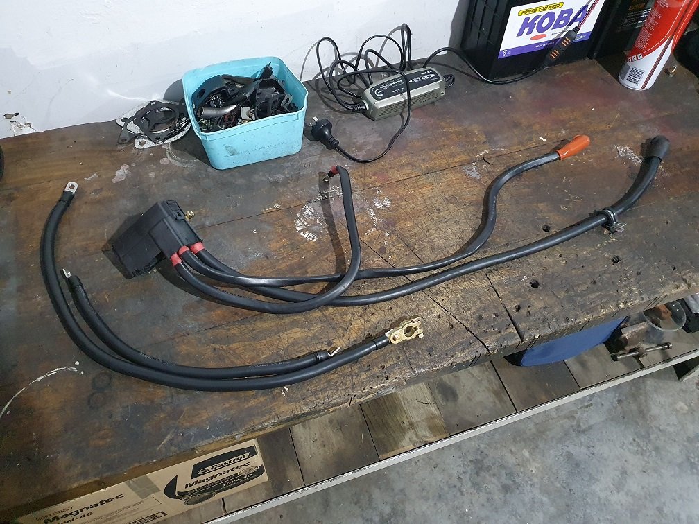
I got sick of waiting for the 'E' harness I bought off yahoo auctions to show up. This harness has all the starting, charging and power supply stuff in it, and not having one meant I couldn't power anything in the car up. I figured I was always going to end up rebuilding this harness, as the OEM ones are all pretty shot by now, but the one from japan was relatively cheap and I was hoping to use it to get things tested initially... I got busy and built the main supply and grounding wires. Everything is a bit larger than OEM (sorry Mazda lightweight engineers) as I wanted to use stuff I mostly already had. Still, nice beefy main battery cables wont hurt. I remember reading a Mazda TSB ages ago about moving the ground locations from the brackets they are originally bolted to, to the body and engine directly, so I built the new wiring to suit this. The positive battery terminal unit is the first power distribution point. There are a couple of connectors that go into the bottom of it that send power to various places via fusible links. There are three cables that bolt to it, one goes directly to the starter, and the others to the alternator output and second power distribution box via the main 120A fusible link. Now I could actually power up all the body stuff. Much to my surprise, most things worked pretty well! Power mirrors aren't giving any response, and the windows are a bit slow to go up and down, but probably just need some lubing. Most annoying was the passengers side headlight. It went up, but would not come down. Looking at the FSM to see how they work I suspected it was the wiper contact on the motor output. Got it out and on the bench and it didn't look too bad... But some attention with some 400grit, cleaning and re-greasing and I now have two pop up up and down headlights. I need to build a bit more of this harness section, as the alternator control wiring, starter signal, and a few other wires go through it. Not a major though. Then I need to build the main 'EM' harness, which is the actual engine control harness, and I should be able to start the thing! Waiting on parts for that, and freight times suck worldwide at the moment... But we're all struggling with that. No rush eh? ;-).
1 point
-
Thread dredge. Tonight I put the motor and box back in it, ratchet strapped it in tight. I won't be touching it in the next few months apart from going for a ride on a trailer.. Next few months are going to be interesting...... Watch this space1 point
-
Feels like it's taken forever but it's now a complete unit apart from master and slave cylinders
1 point
-
Clutch kit didn't arrive, oh well. Pulled the stick off, pretty bloody rusty. Cleaned that up and gave it a lube, and in typical fashion the bloody e clip went flying upon reassembly. Gave it a wash this morning and a wire wheel just now. I'll paint it on the weekend
1 point
-
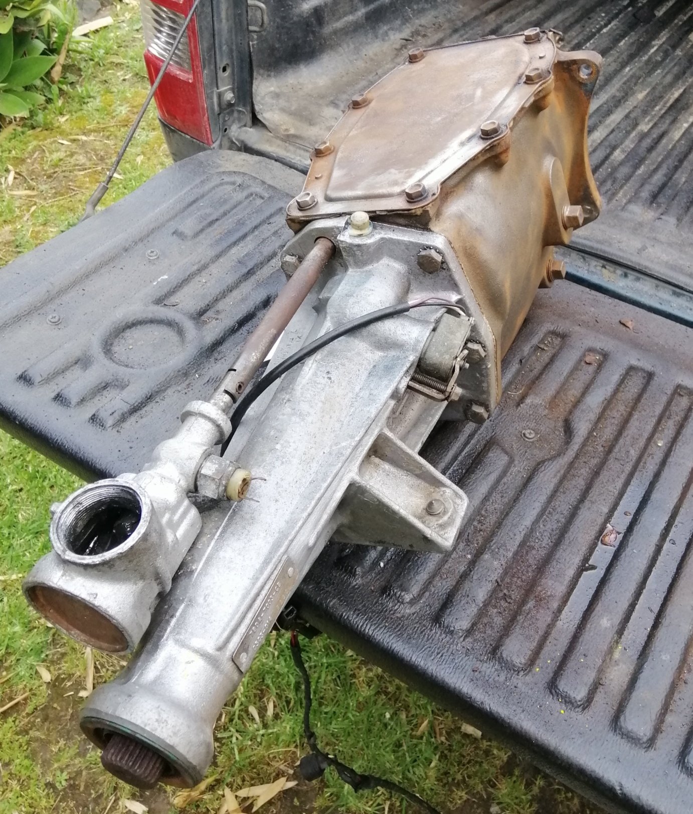
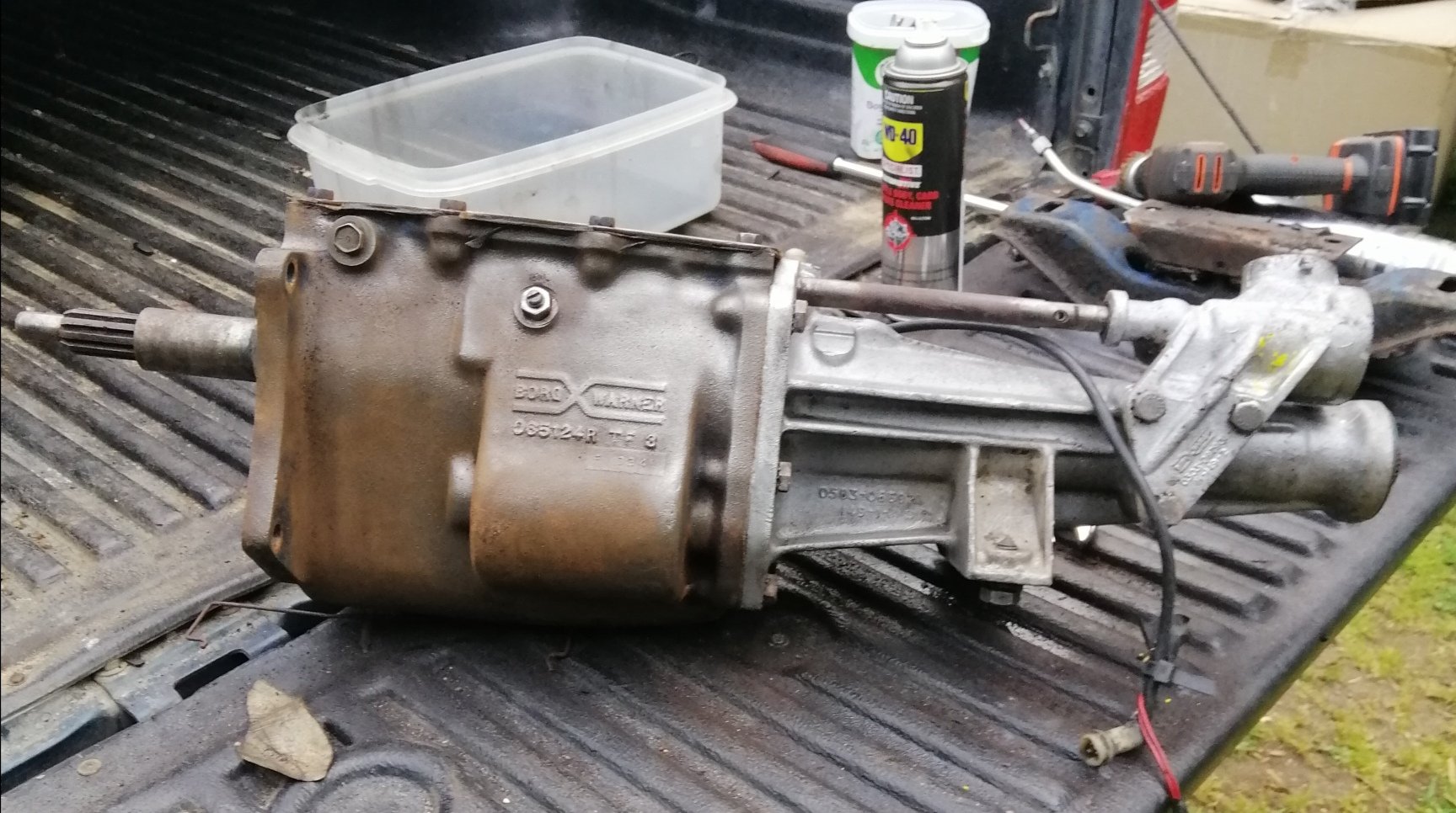
Received confirmation new gearbox is a Borg Warner single rail 4 speed, as to whether its a close or wide ratio box I will find out upon receival. Goon was supposed to deliver it to Old Boy yesterday at the track. Bah, wait another week or so.1 point
-
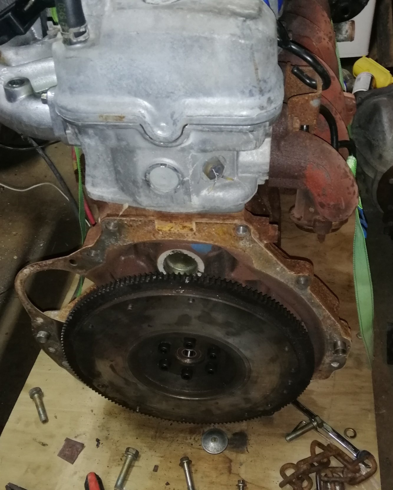
Had Miss13 as an assistant last night. First was punch in a spigot bearing. Part number 6003-2RS for future reference. Bit of hands on experience in the way of roughing up the flywheel. Fit flywheel, found 2 bolts don't line up! Quick call to Dad to confirm and he has struck it before. Also confirmed in Fordforums. Mark out the two offending holes and slight finesse with a file. Forgot to photograph this stage. I made a couple of tiny packers and put them in the voids to take up any play that may occur. In speedway circles it is common for guys to bore all 6 holes oversize, but this has a tenancy for the flywheel coming loose. This is a better alternative. Gave Miss13 the job of applying Loctite threadlocker to the M10x1.25x30 12.9 capscrews (quoted for future reference. Torque to 100nM, spec is 83nM, was recommended by Fordforums member as at 83nM he was finding flywheel coming loose. He used this method, (slightly longer capscrews, Loctite and a little more torque) and has had no further issues
1 point
-
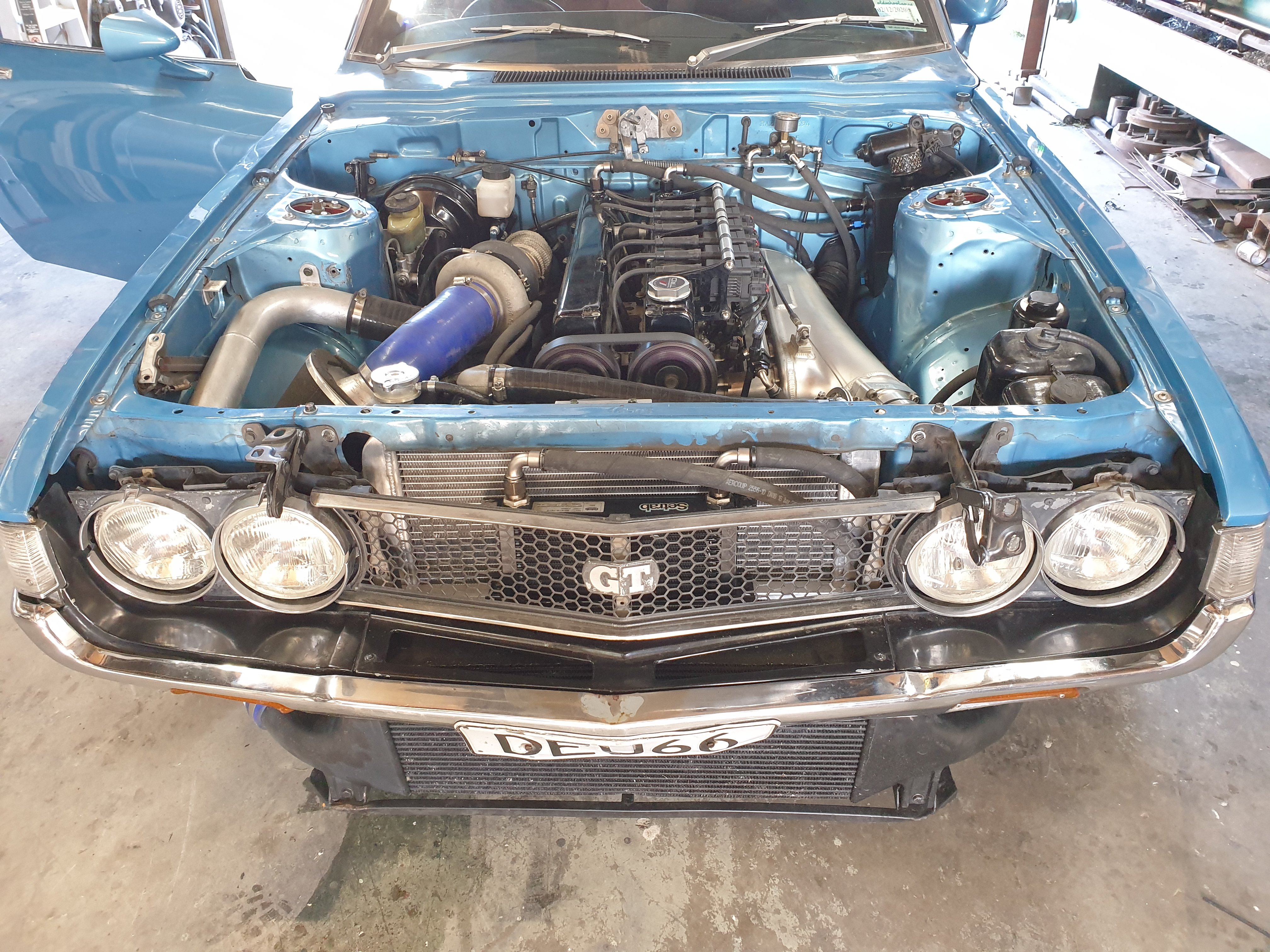
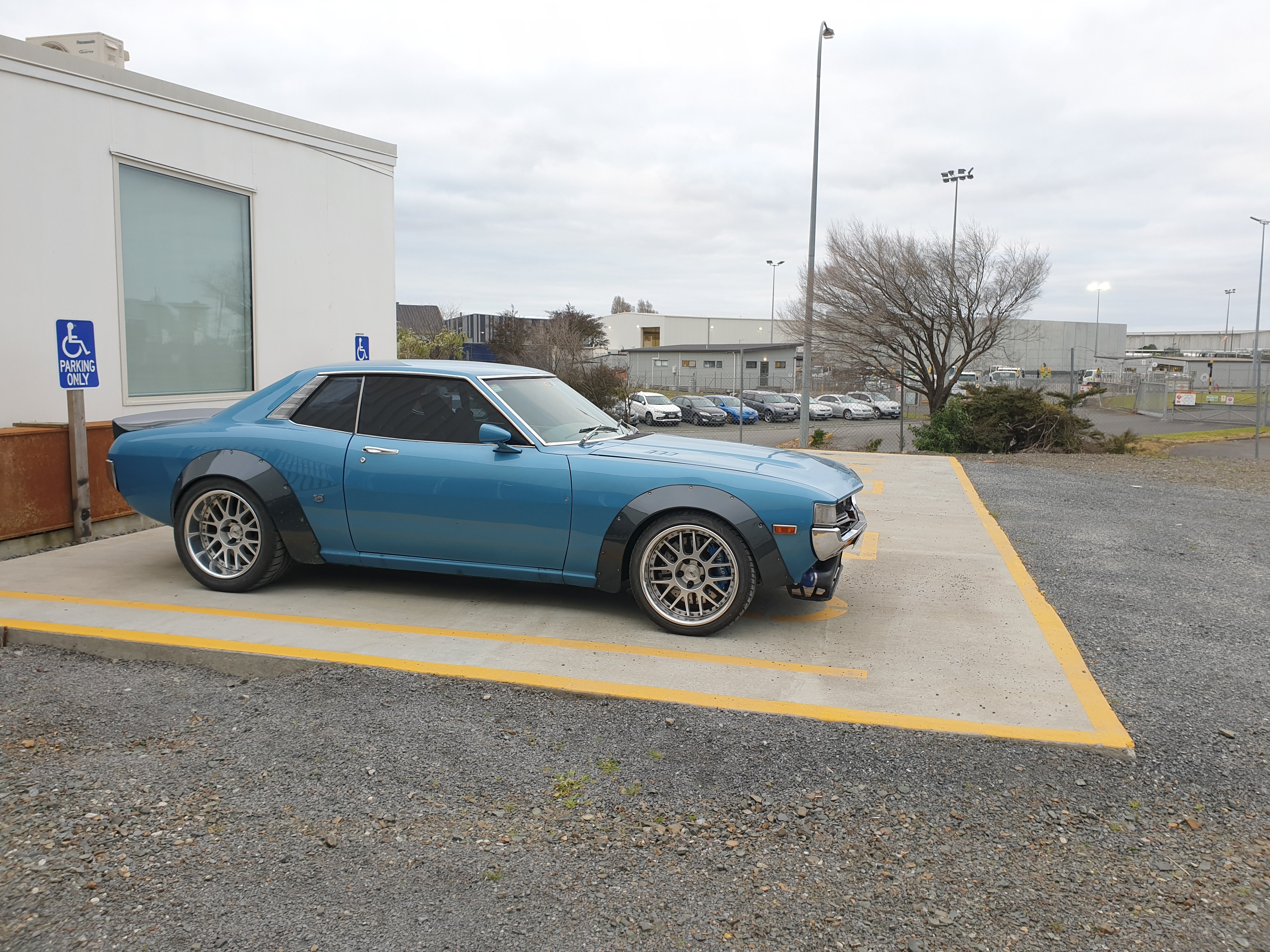
All back together now. Had a turbo shit off a time getting the heater hoses back on because some idiot stuffed a huge motor right in the way. New clutch (remember that, the reason we pulled it apart in the first place) is really good, it's a tiny bit grabby at take off but it's not really bedded in at all so I don't know if this will get better or worse. Also i have connected the boost control pipes around the wrong way so it's free boosting up to about 30psi. Easy fix that. I drove it to work.
1 point
-
Old mate @ruff kunt automotive aka RKA tigged it together today. Needs some minor cleaning up but I'm stoked with the result
1 point
-
Quick swap over this morning. Hasn't got a flywheel at the moment, at least I can mock up. Manual setup come out of a dirt car
1 point
-
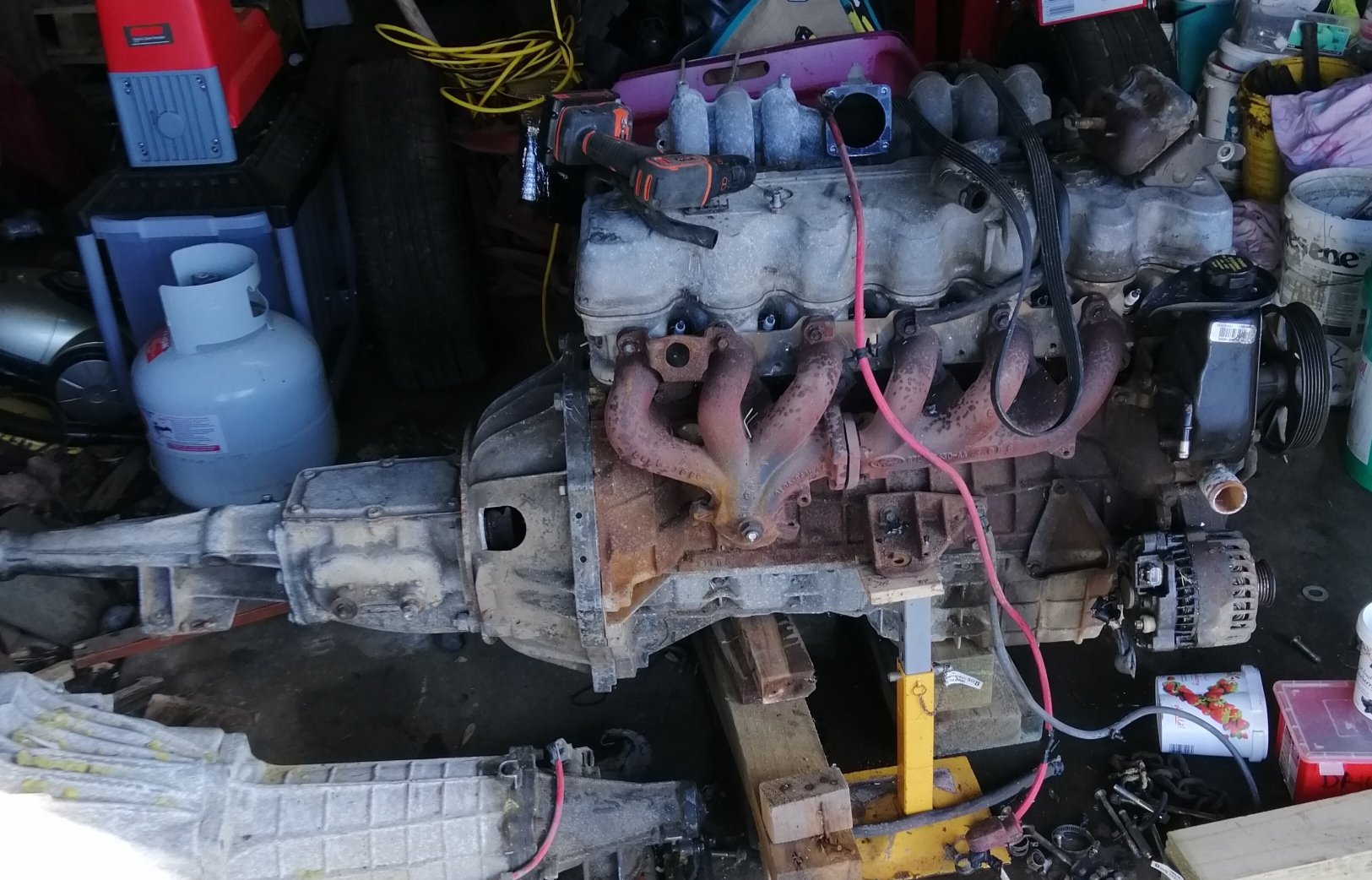
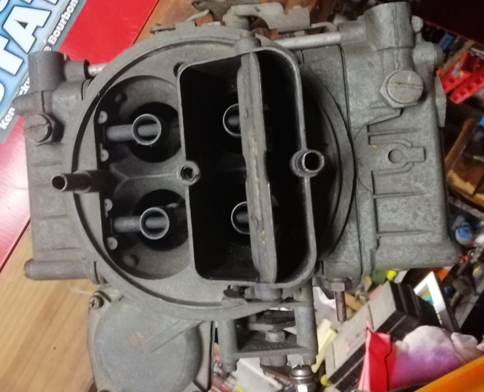
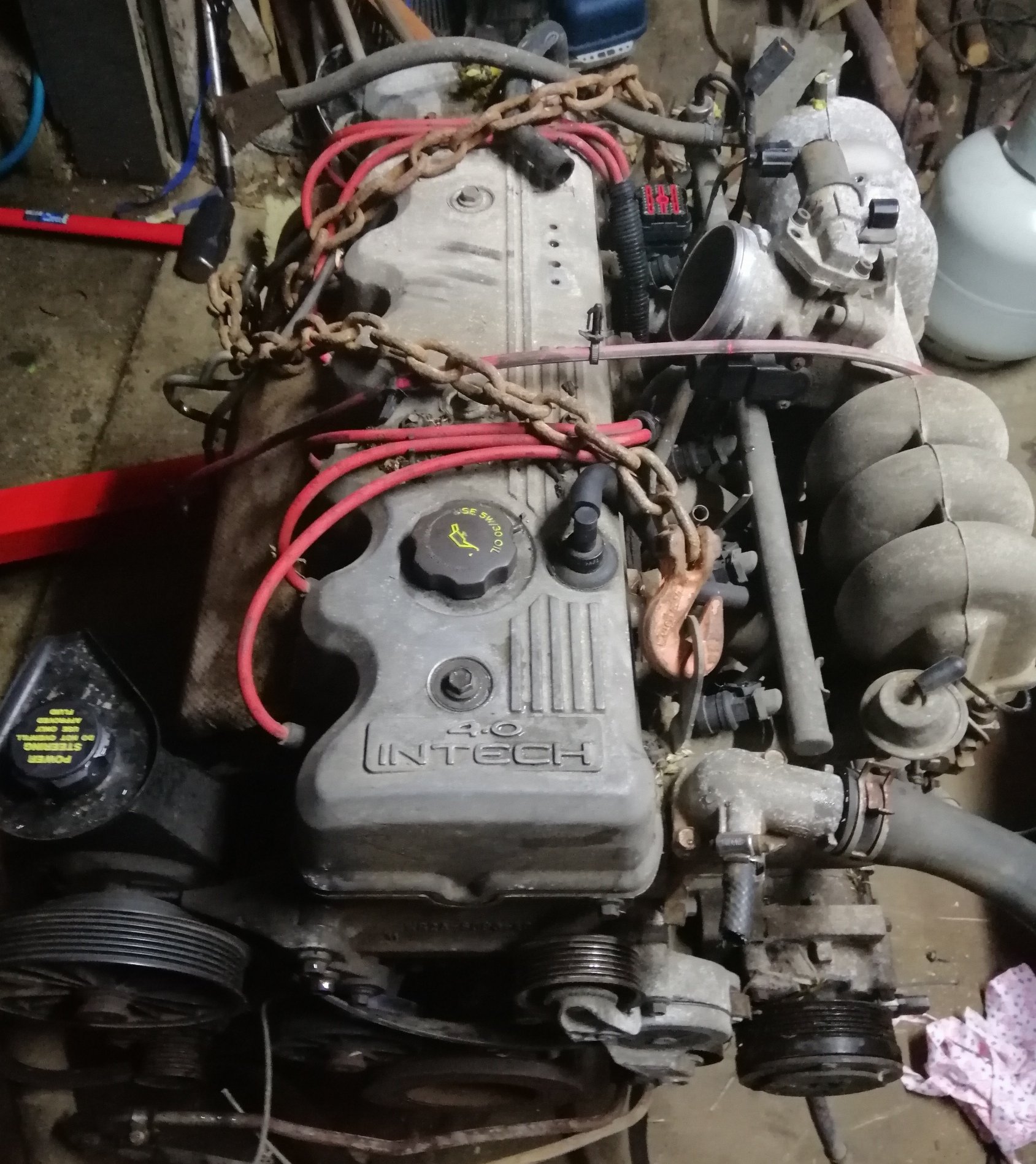
Here it it. 4.0l SOHC Falcon out of a AU3. Done a Derby. $50 Special. Also have a dirty Holley 4bbl and a turbo off something to go along with it. Have manual bellhousing and 3 speed up it's bum.
1 point
-
As mentioned in spam I'm tired of waiting. Thanks to old mate @rb drifter we are off to collect a specimen tomorrow. Certainly not Hemi cool, but I think what I have in mind for this should get the forums approval. Pictures tomorrow......1 point
-
Another pictureless update. Thought before I get àll skippy and build a seat I'd better check with lvvta the best way to proceed. As stated before the 4 seat idea has gone. Have had lengthy forum discussion as what this is classed as, and it is classed as scratch built. So I'm going to put 4 point harnesses in it, which means it requires headrests and apertures for the belts to go through. High back bench seat design is commencing....feel free to throw up ideas in the discussion thread if you got ideas, I'm struggling......cheers1 point
-
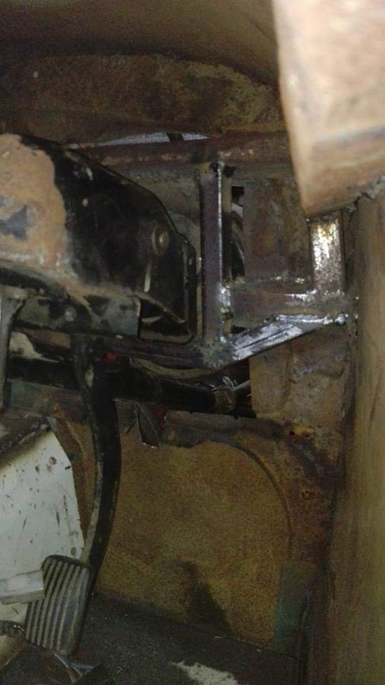
Haven't been around for a while. Work/life epically busy but I am back into it again. I fucked up due to lifting the cowl up. So what goes up must go down. Chop up the cowl and reinforcing and lower the pedalbox and steering column. Pics or it didn't happen Made a purchase of 50x50x3,more 25x25x3 box,100x3 and 50x3 flatbar today. About to start the seat and seatbelt anchorages (the tricky shit). I've given up on the idea of back seats, just way too much political shit to deal with, damn you lvvta....
1 point
-
Bolted sidies on for shits n giggles. foul on no6 header pipe, meh. they getting chopped anyway Ive cut n shut the back of the body And the back joins to the front, about to put a swag of bracing in and a zillion cuts out of the 25x25 box to achieve a curve for the "doors"
1 point
-
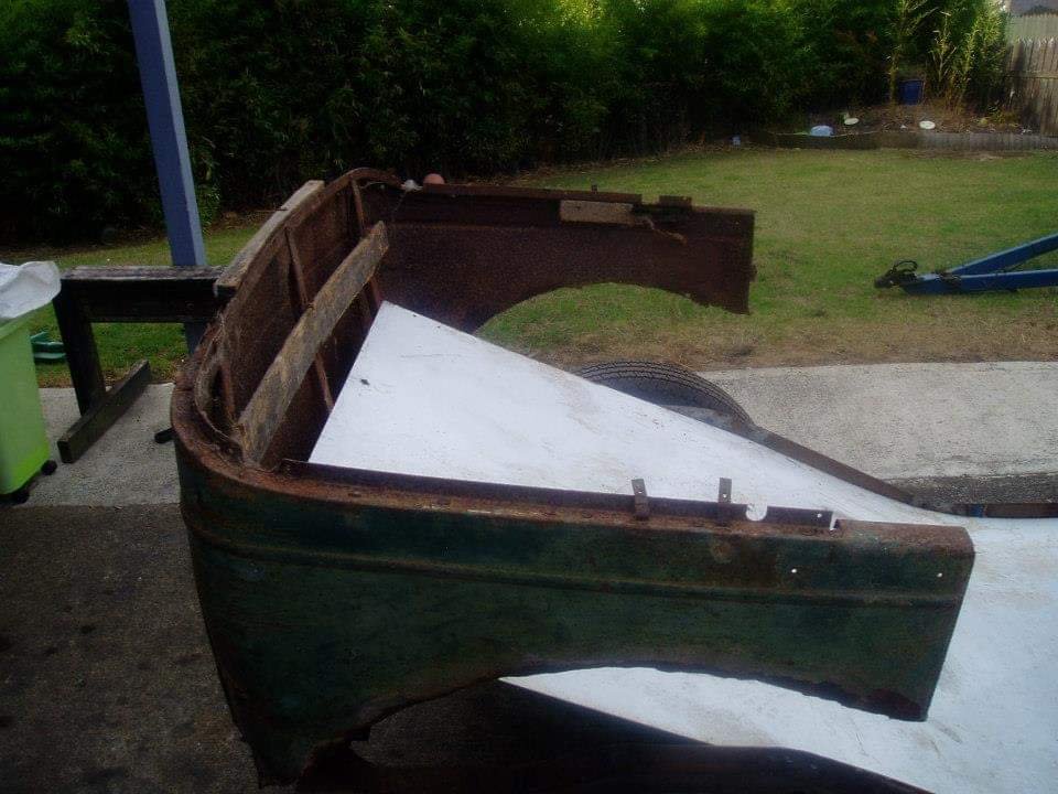
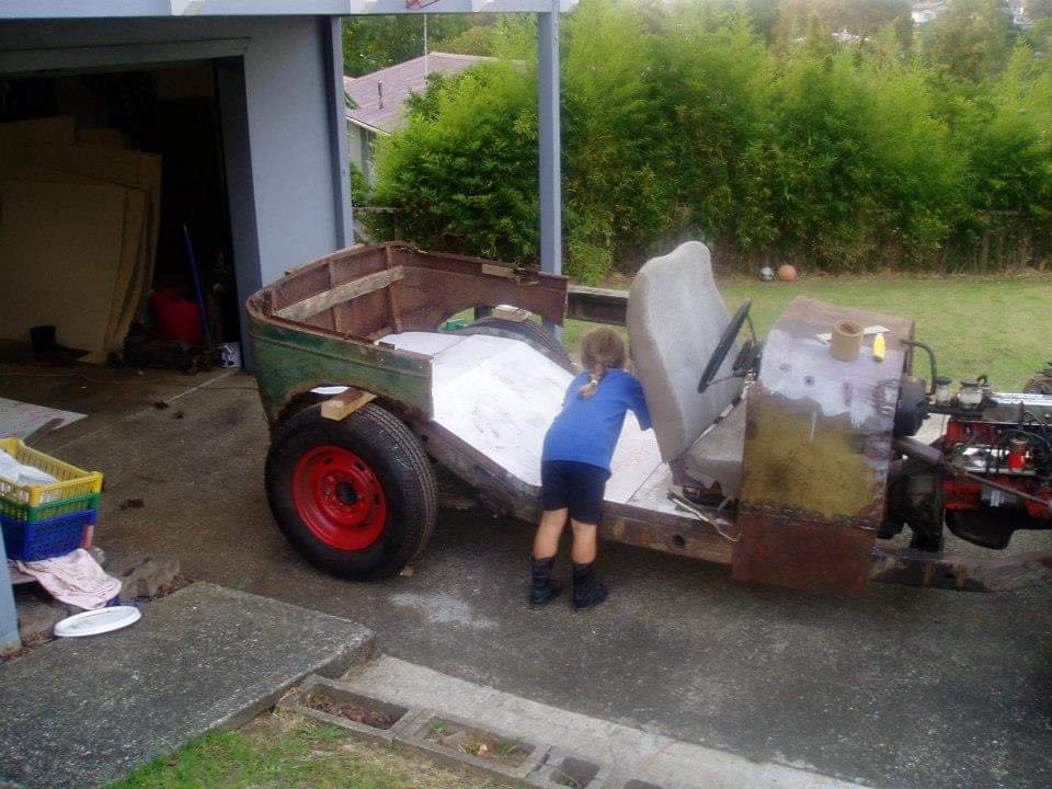
Productive night tonight. Fabricated a rear floor, freshly bent with trusty old Ford and Wood precision bender. Pretty pleased with the end result I also acquired this piece of antiquity, been told it is Model A Ford. Its in poor/fantastic condition for ratrod. Nothing the welder wont fix. Roughly in the right place, this section need to be narrowed by about 250mm to fit the bodybase correctly. This will save me hours in fabricating a rear section, but there still is hours of repairs to be done on it, which is just adding to its character And I scored some awesome help in floor decoration from my youngest Daughter Abbey
1 point
-
Did a little bit more last night. mainly the final cut of the rear of the chassis. in total there has been about 650 mm removed off the rear. Ive got a nervous 6 weeks ahead of me, big big changes, but not going to jinx it yet. If it goes ahead this will be on hold for quite a while......1 point
-
Got hanger position sorted! Still a bit more chassis to get whacked off. Commencement of building the body imminent!!!!!1 point
-
Got the springs back ($300) until we get load on them we dont know whether we need the 2nd spring. The new ones are the shorter of the two. Lost pic.... Removed the old shackle mounts and cleaned em up nice Lost pic.. Old boys into the crossmember with the gas axe!!! Lost pic... General mockup of the new hanger position, more grinding of chassis required1 point
-
Todays effort was to remove springs to find bushes absolutely shot. Taking springpack to local springmaker on Monday to see what he can do, ideally 200mm shorter would be awesome but 100-120mm will suffice. Going to get reversed eyes too to help with height issue. Also hoping we can do it with a single parabolic spring,depends on what the man says. Removed the mount. This section of chassis is going to be cut off then the spring shackle mount is to be reused after careful grinding to remove excess metal, the crossmember in the background is also going to get replaced by a more presentable boxsection one So yeah, all this craps gotta be done prior to starting the body.....piss me off.... One step forward 10 backward....1 point
-
Last nights mission was a brainstorm and figure out night. Decided to stay with the Mitsi diff, and use a 750/15 12ply truck tyre, which by some formula counterer thingee on the enet gives us a final drive pretty close to an HQs 3.55..... Also made cardboard templates for the engine mounts that will be made out of sculpted 75x3mm flatbar. Front half of the driveshaft is almost ready to go to the engineer to be welded, Not going to balance it because it is a total of 365mm from centre of universal to yoke spline... see if old boy is keen to do some work tonight.... edit, which didnt happen....1 point
-
Bullshit update. Reversed the crossmember under the gearbox by cutting the bottom off and welding it back on the top, looks choice. Took couple of hours to get that right, mission of a job.1 point
-
Cowl now (almost) welded together (inside and out) and started filling random drilled holes with weld. Havent ground the welds yet. Have made pact that this is having no bog whatsoever to any part of the body, all warps from welding are staying, no weld is to be ground flat completely,1 point
-
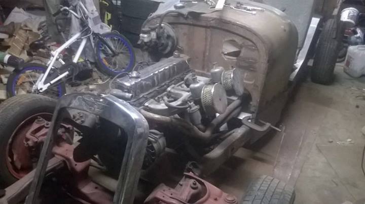
Few pics from last night, phone battery died prior to photo of tacked together widened cowl. Pretty nerve wracking taking a zipdisc to an 89yr old part, did NOT want to fuck it up. Engine in its approximate place, need to figure body height, seating etc first to decide its final position.
1 point
-
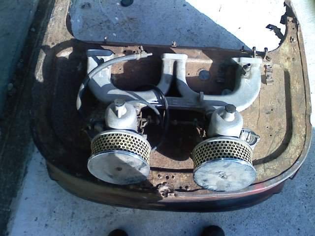
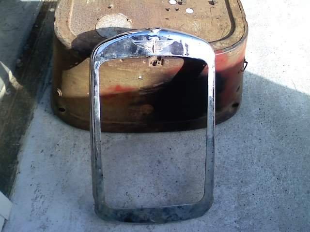
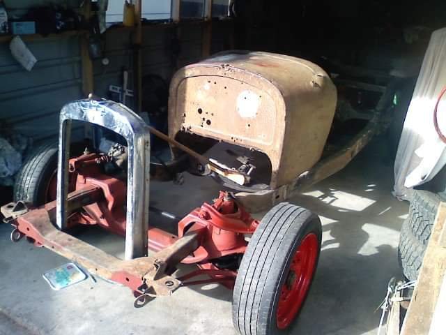
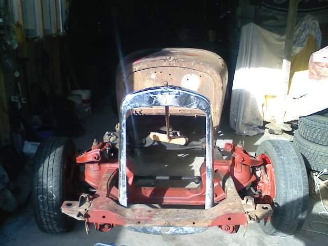
A few random pics of my pile of bits Chassis front Carbs and Manifold Grille surround Quick mock up Dodgy cell pics sorry
1 point
-
Well no joy yet with a flexplate, bugger it all, but on brighter note scored a meke patina'd to fuck (ie rusty) chrome rocker cover, keen to source similar rusty stz chrome sideplates. Will look so rat it will leave rodent crap everywhere......ps still waiting for data cable by dude assures me he will have it for me tomorrow. TUI Yeah right.......1 point
-
Well still no data cable dammit.... Anyway boring update, due to infliction of pain to groin region, the chassis got abbreviated from just behind the spring hanger!!!!! (Hurt too!!!) and removed the original gearbox crossmember for modification (ie sustantial chop lower and reinstall) and have finished grinding up the leftovers of the cabmounts. Easter, well, no work will be done on this old girl, consumption of malty alcoholic substances for 3 days are beckoning. Over and out.1 point
-
Cut the cab mounts off today and ground flush. One needs finishing touches but ran out of sunlight. Shed Im building it in(Dads) has no power connected yet. Hes off to reterieve his engine hoist sometime during the week so we can elevate the motor to change the sumps over. Then dangle the engine in approximate position for relevant measurements to make the engine mounts. Edit Ill throw some pics up when I get a data cable....1 point


This leaderboard is set to Auckland/GMT+12:00