
Leaderboard


Popular Content
Showing content with the highest reputation on 07/13/21 in all areas
-
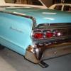
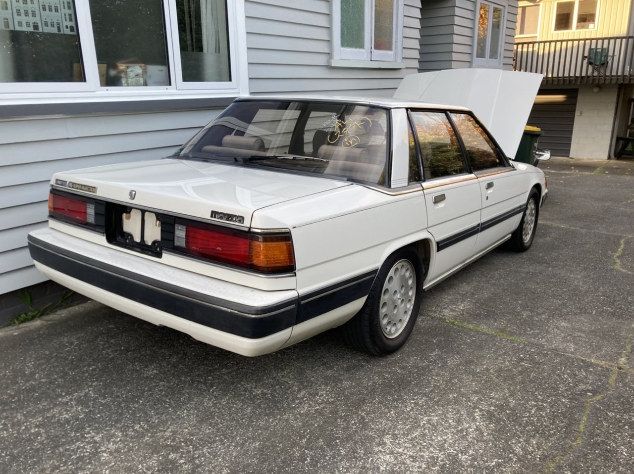
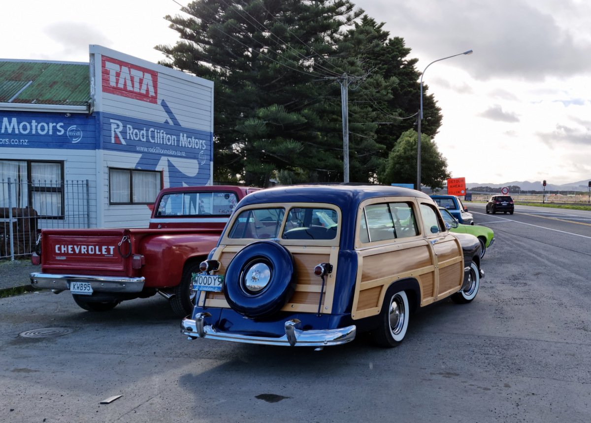
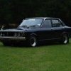
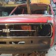
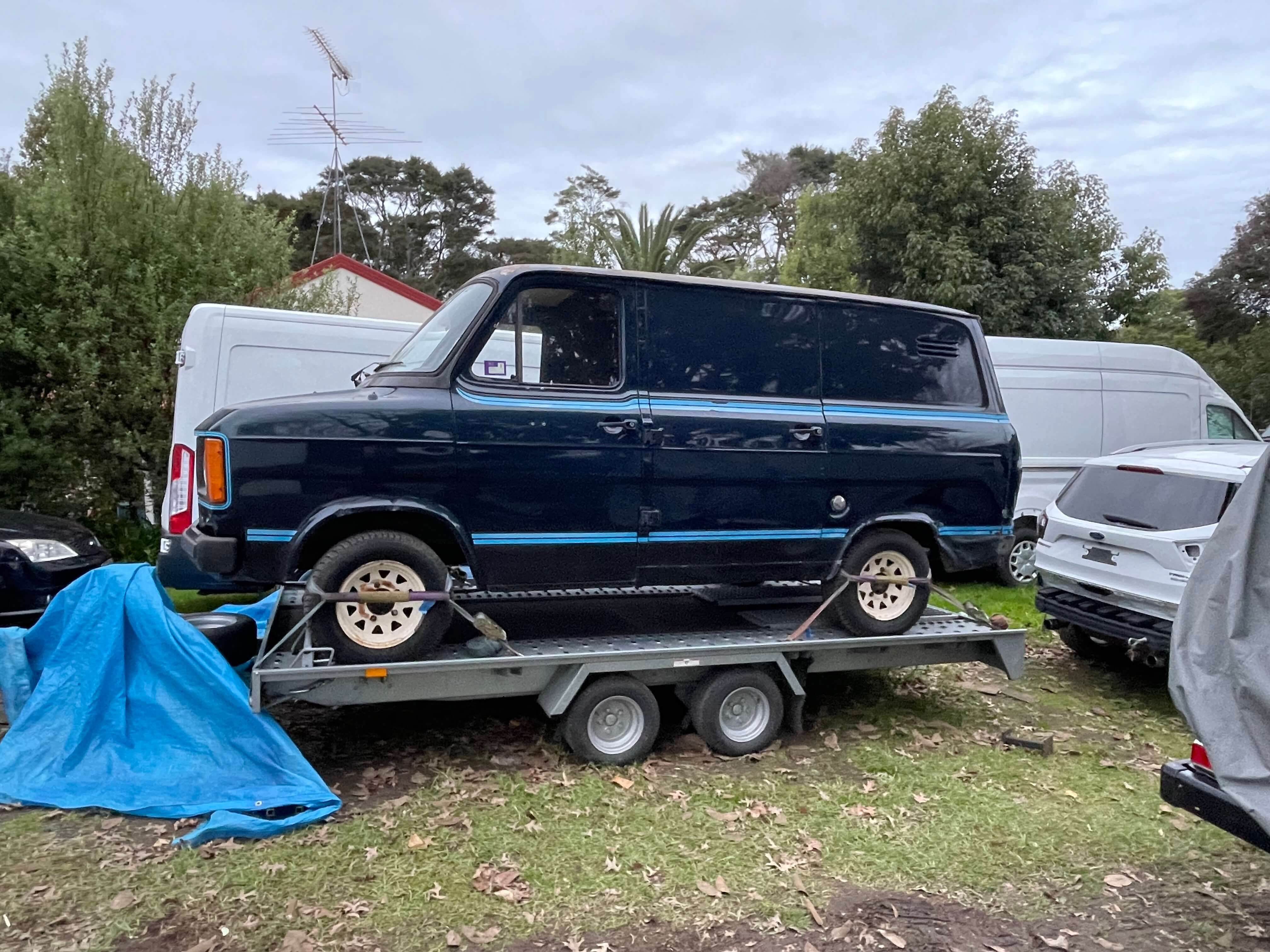
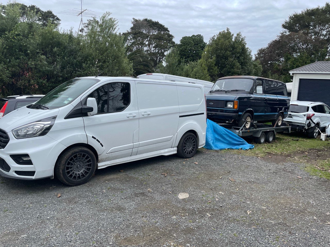
This showed up at home today - pretty happy with how tidy it is, certainly not mint, but I would have been shocked if it was. Flat battery, no engine coolant and a little exhaust leak will be the first little jobs to do, along with oil change and filters too. Chatted to a local compliance place that will do a pre compliance check over and point out any likely repairs needed, before doing a full on compliance inspection so will try get it to them in the next week or two
 24 points
 -
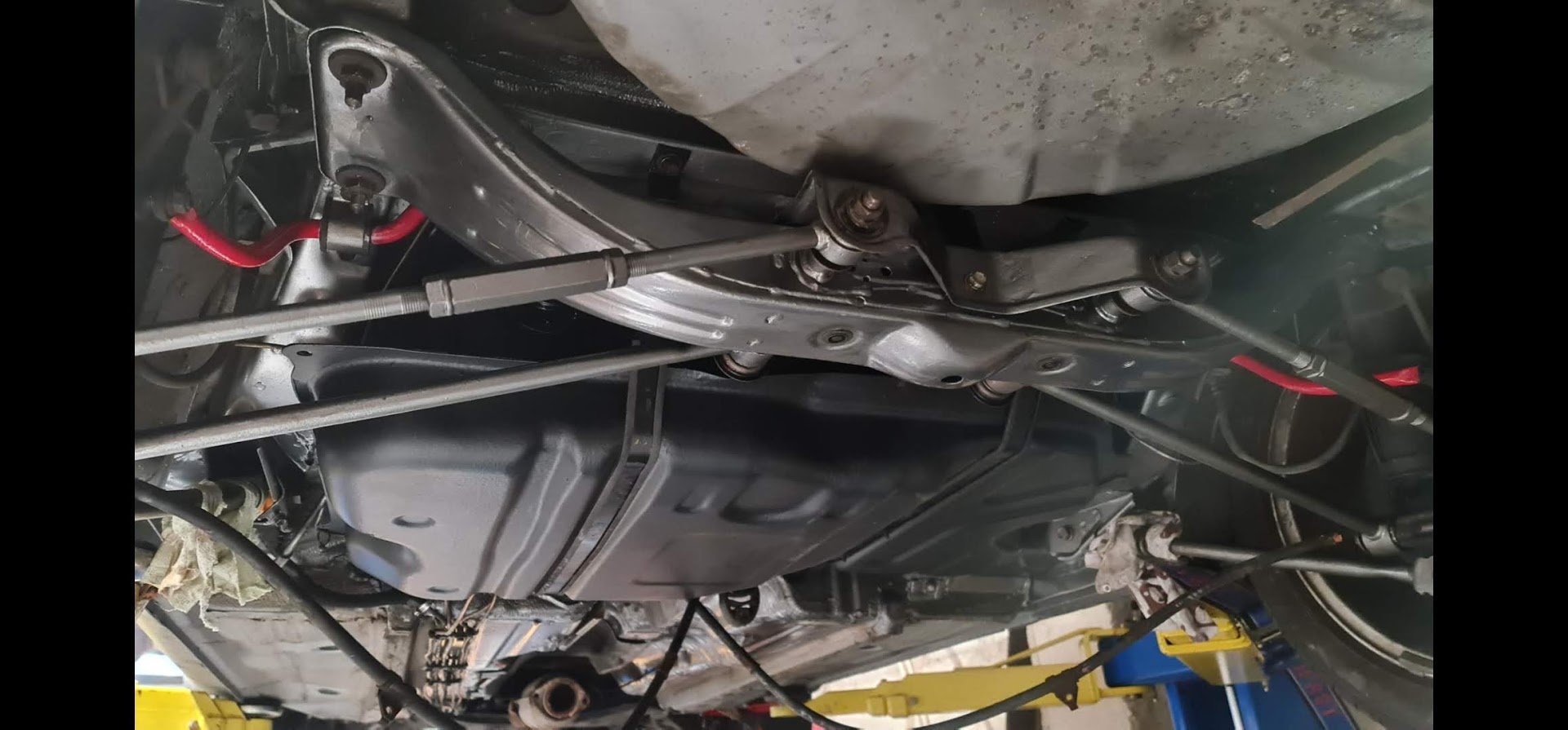
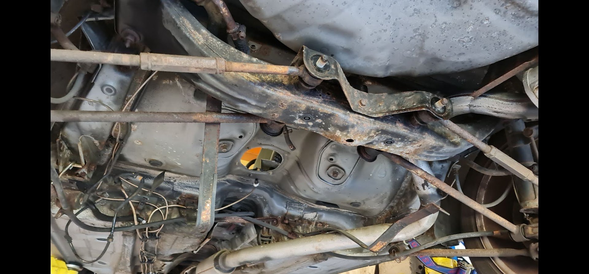
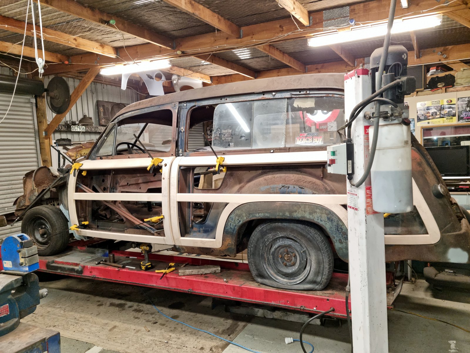
So a long overdue update. Put car on a rotisserie for inspection, and not great news... Surprisingly for an EA coon there was some rust issues and the certed roll cage was, well, junk... Bends all had deformation/wrinkles, welding was sub par, and wall thickness was pretty thin... So this happened. ED? body shell bought locally for around 3 hundy. Bloke wanted to keep the engine so we yeeted that out for him, so easy with workshop crane... And front suspension was bent so new mounts etc need fabricated. Rally car block is in the engine shop but bloke there had a fucked Clevo block we used for a mock up. Apparently have exactly the same mounting dimensions as the windsor, which makes sense... So we lifted that in place to find the optimum position... And will make up mount modification blocks to suit... Body is actually in really good nick, and new roll cage is well under way... Proper steel, properly bent, properly mounted, and properly welded (not by me, obvs)... Owner looked at using a long crank/shorter pistons for rally torque, but got too hard with supply issues atm (even Summit couldn't find right parts) so he's ordered some pistons from Aus. Also new diff being built in Ch'ch after some bits were found to be missing... Think the axles are being modified too for rally use. So things are coming together, he's looking fwd to bolting the engine together and putting things back in the painted shell when that's done. Financially the initial purchase has not proved great, given all the gear being swapped, but he's philosophical bout that as it's given him an interest/something to work on. Old car life eh...13 points
-
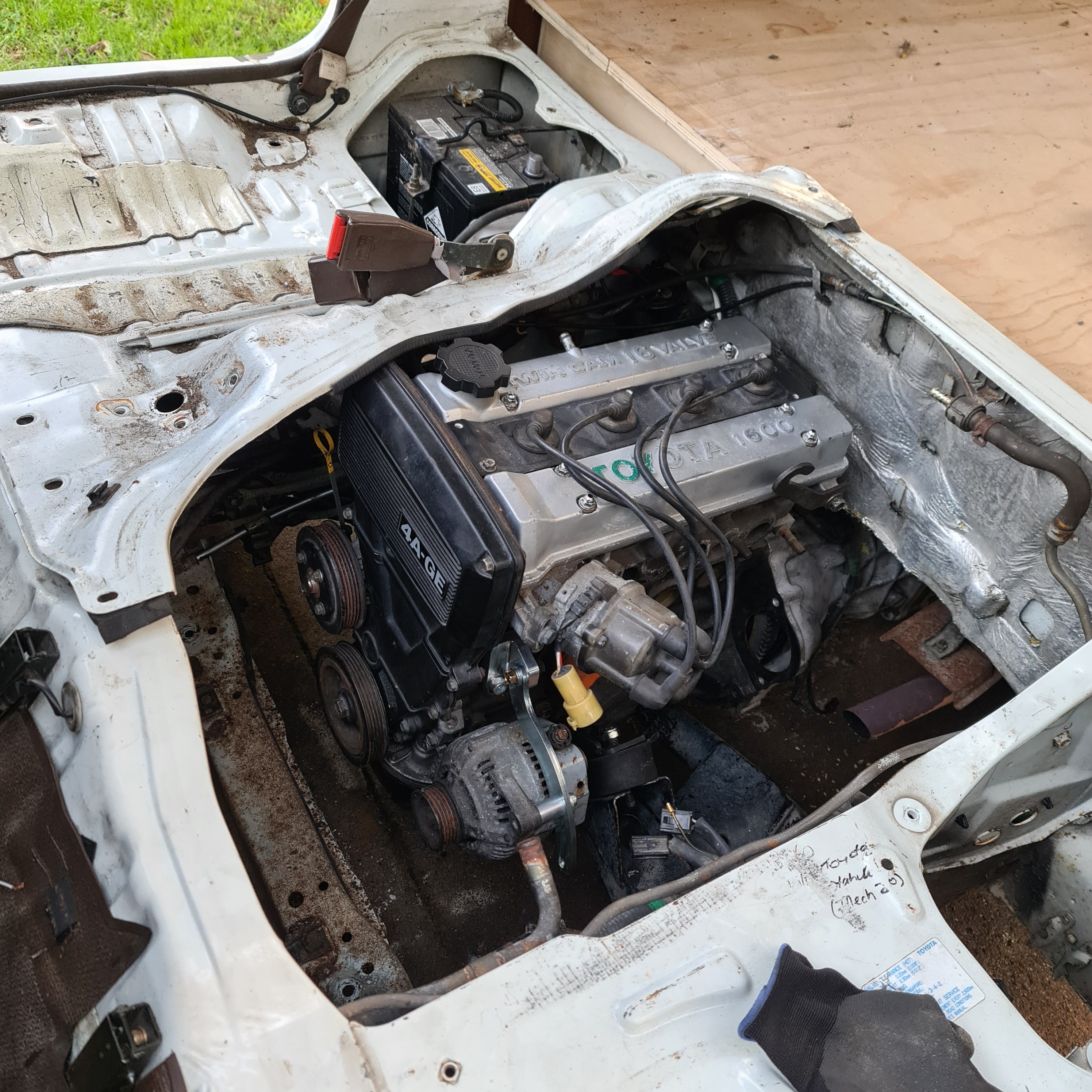
Fire in the hole four bolts half wound in from bellhousing side and rest onto mounts. you can just see in photo sump is fouling on the removable stone guard which is holding engine up. Test fit of drivers half of bonnet shows its fouling by hopefully the same amount it needs to drop down. the untrained eye says the carbs will fit. fingers crossed
13 points
-
It’s still progress even if it’s to cold to do physical work on it right? Ah shit, wet mangled box phew not rooted! Some damage to the tulip/deck filler/Dutchman panel but easy fix. even included a bonus fancy Honda trans mount with an electrical sensor some poor sap will be waiting for on a 2day service! This only took a week to arrive!9 points
-
Another hour fiddling this afternoon. Dropped the stone shield and the motor dropped down. Test fit drivers half bonnet and it's still fouling. Might try @BlownCoronasuggestion of offset and maybe thinner engine mount to get it. 20mm drop would be perfect. Carbs look like they will go also, might relocate the coil to passenger (maybe not since exhaust?) If I can sort the drivers half of bonnet passengers side will definitely work as its raised again
5 points
-
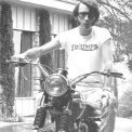
Yeah I'm pretty sure the CT had a sticking rear brake that entire ride sorry. Has new reflector and straightened number plate now . Might even fix the exhaust leak for whomever is lucky enough to pilot it this year. That bikes been an attendee every year now.4 points
-
It's still not 100% but I'm not gonna lie I'm stoked with how this is going to end up looking (Wont be white for final version)
3 points
-
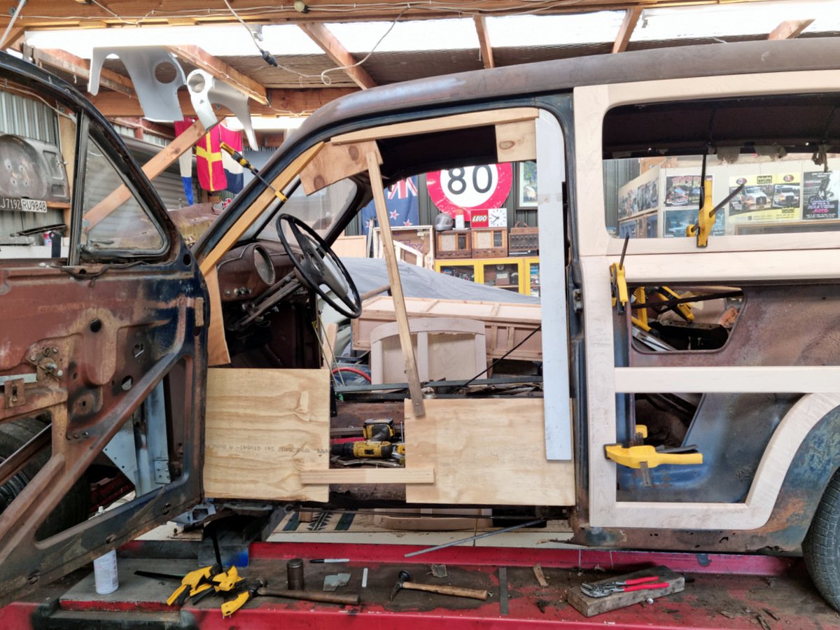
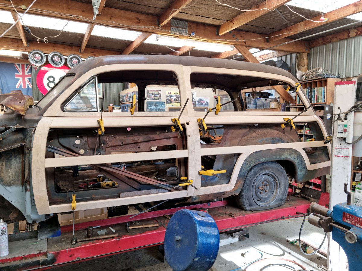
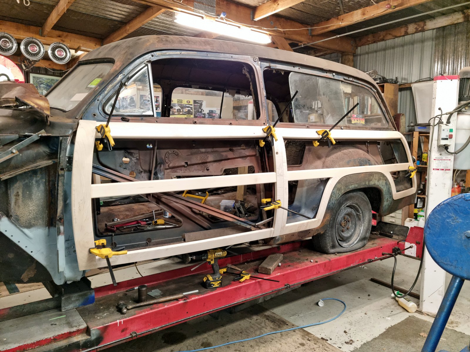
Made up a door template from the good car. Fits 'OK' in the project for a start. I added the upper parts too to check the vertical positioning. I sent some pics to the wood man and he said it's not the worst he's seen so I suppose that's good? Also took the new one out for a breakfast run and tour of some of Rod Clifton's tractor patch.
3 points
-
Theres some big climbs to battle to stay on pipe this year too With the bonus of being gravel2 points
-
That's the section where I nearly melted the TS100 last year having it absolutely singing not realizing the carburetor had fallen off2 points
-
Easy does it lots of lifting van, repositioning scissor jack holding gearbag and again with axle stand for missing wheel. Rest on seat frame to reposition again
2 points
-
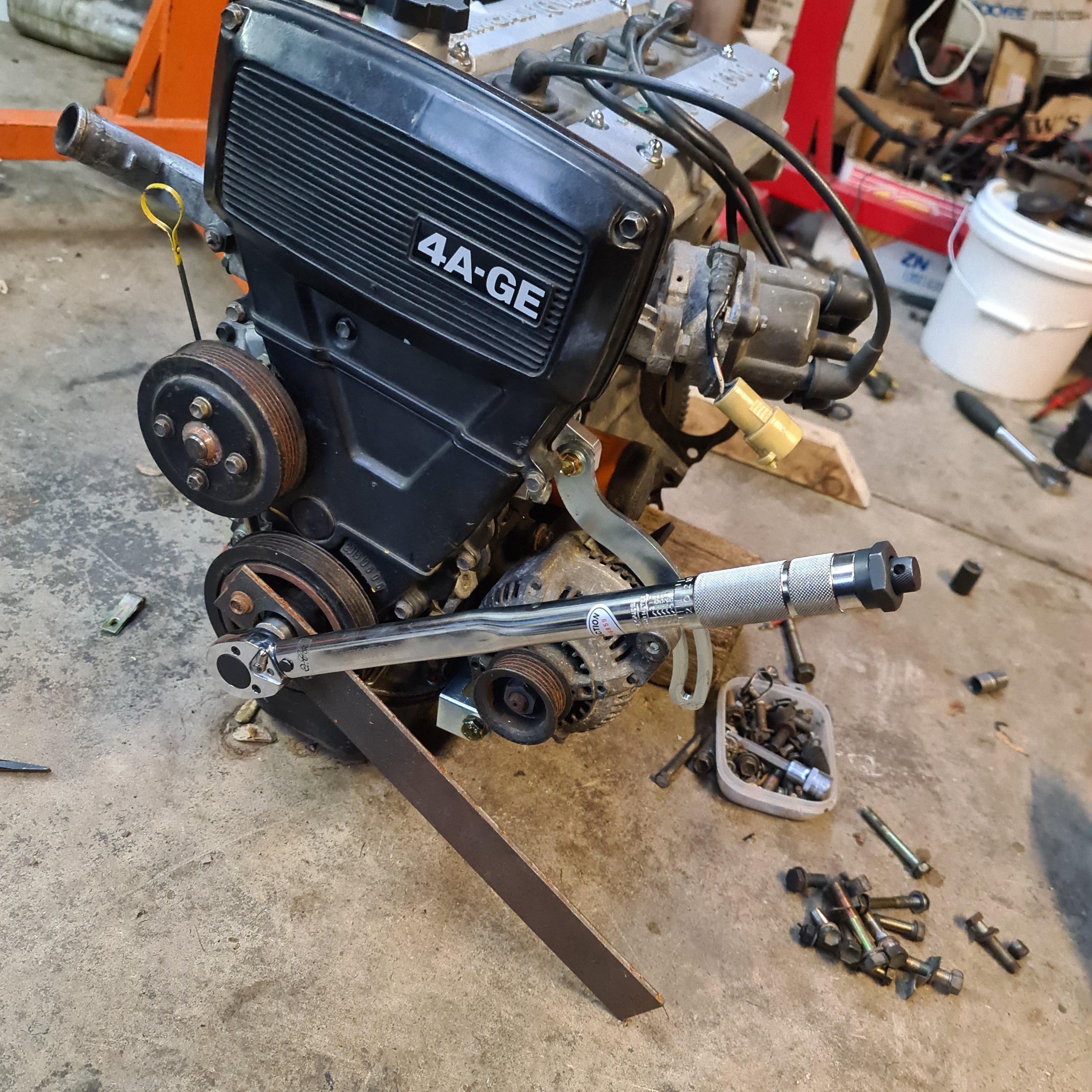
Left over toyota SST from my 1gge fiddling for holding crank while I torque pulley
2 points
-
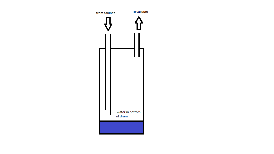
I use a drum with some water in the bottom as a pre filter, the inlet from the cabinet goes down almost to the water level with the idea being the dust gets caught in the water as it flies down into the vessel out of the inlet pipe. seems to work ok my free vacuum hasnt died yet and almost no dust comes out of the vacuum outlet which I pipe to outside.
2 points
-
@Kassis helping me build this. Old Honda C110 frame from the early 60's. Front end (forks and wheel) + the swing arm/rear wheel are from a 2008 Honda CBR125. Will attempt to retain the monoshock for the rear. Tank is from a 70's? Honda CB100. Engine will hopefully be a 5 speed DOHC FX125 engine. It's a lot of work and we're barely started but it would be the ultimate off road pest machine for me. I was super excited about my alloy mags till I saw what happened to Aaron Card's wheel on molesworth, but just gonna send it. These are Honda branded Enkei's which is pretty cool for what was an entry level learner bike at the time. Disc front and rear will be absolutely lush. I have a fat 5.10x17 Shinko dual sport coming for the rear. I managed to get the original CT125 handle bars and switch blocks from Aaron's new CT125 he's chopped. Saw the Vietnamese dudes in Ho chi Minh using modern Honda switch blocks on old Dax's and Chalys and it looked kinda cool. Anyway, enough writing about it. Time to go and build it. *seat is from one of those old low rider chopper bicycles and was just for lol's.2 points
-
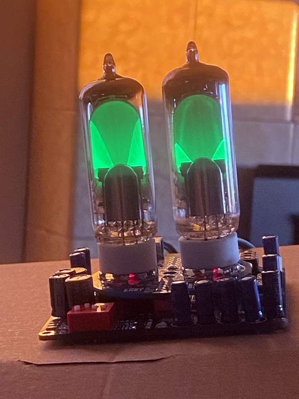
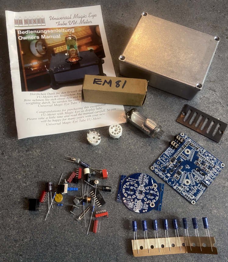
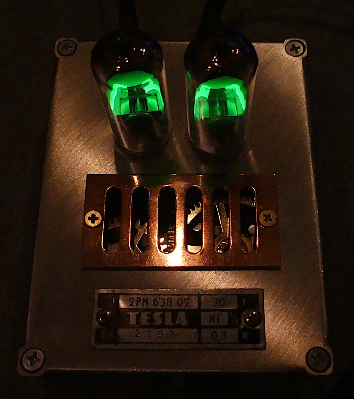
My magic eye VU meter parts arrived! Magic eye tubes were used as signal strength indicators on old valve radios, to help show you when you'd tuned the station accurately. Fast forward 90 years and this kitset just makes the tube displays dance to the music. I went for a pricier kit, but made up for it by getting the tubes on TradeMe and supplying my own case. Here's the kit assembled: I set about installing it in the project box and started to freak out that it would look like a monster face - the box for the head, tubes for eyes and a grille for a mouth. I added a Tesla nameplate below the grille to try to minimise that, but from some angles.... Anyway. Here's a video. Behold the pointlessness!
2 points
-
Just putting this up to keep track of things. Mate bought an old EA rally car last week after pining for an AU. Essentially he knew this one was out there, rang the owner and did a deal. It's an EA, converted to V8 mustang, 5 speed, all roll cage certed etc. Picked her up Sat morning in gay old Gore and drove it onto trailer... And a snug enough fit for the drive home... First mission was a good hot steam clean inside and out, lichen on the body and lots of oil on the engine, it is a detuned 86 5.0 donk, that somehow manages to strangle itself to give 150kW... Bogan VB bought specially for the occasion, did like the old badge... And all clean, pouring water out the speed holes. A new paint scheme will be forthcoming...1 point
-
Added entrants to first post. Is there anything I'm missing? How is everyone getting on for accommodation?1 point
-
C u's thurr1 point
-
Yep yip, axle retention works, got it. Makes sense. Maybe a HD bearing retainer set up with a spacer or something to preload the seal even more than stock. Cool. Ta man. Cool diffs them Borgies.1 point
-
Fuck yeah booooooiii!1 point
-
Sounds good, I can make it to two in a row, what a treat1 point
-
Mmmmmmm, RIBS! I’ll be there. +11 point
-
Apparently it's something to stop them hitting the seals under rally stresses? Standard they are ok on roads but I think they put a stop/flange/something on axles to stop them hitting seals and coming loose. I'm too mechanically derp to understand, was relayed to me as recommended to owner by diff specialist. Can find out if you're really interested...1 point
-
My interpretation would be if it bolts to existing points ie the shock mounts then no cert required, but if you have to drill holes= cert1 point
-
Compared to the liftback it flexes like a wet paper towel. Creaks going up curbs and things. Fitting a rear brace to a legacy wagon made a huge difference in feel, so I'm hoping for the same with the Carib, but the design of the strut tops makes mounting a brace in the normal way a bit shit (and there are zero off the shelf options for the wagon as it's different to the coupe/sedan).1 point
-
FYI there are such things as engine mounts with offset bolts that would make your current setup bolt in. when we put the sr20det in dads s11, we had i think 35mm difference between mount and crossmember, had a google and came up with a volvo mount that had the same offset and everything bolted in sweet with off the shelf parts.1 point
-
It was so hard to get it on the pipe and keep it there up those big hills. This video makes me think I should get a new clutch for this year...1 point
-
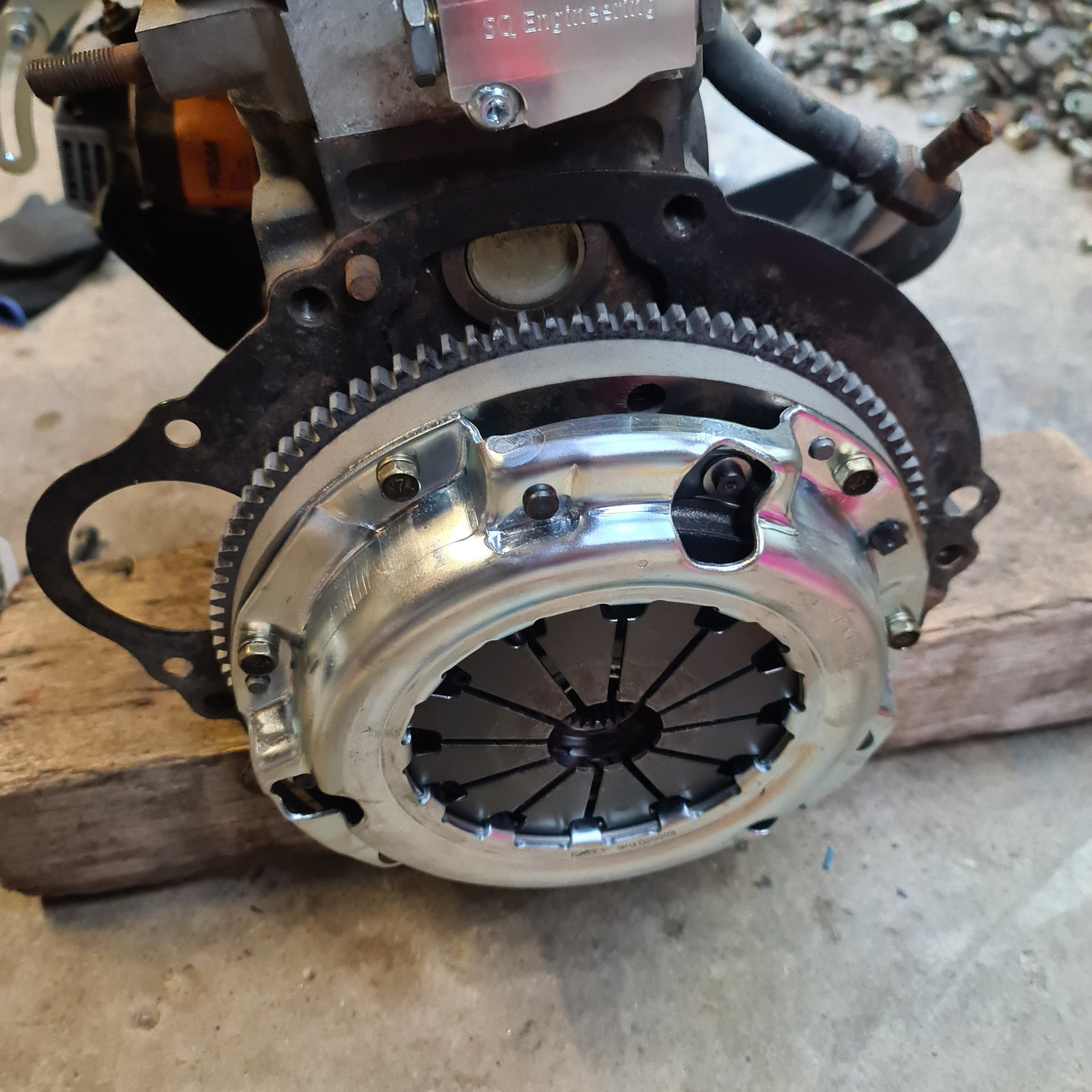
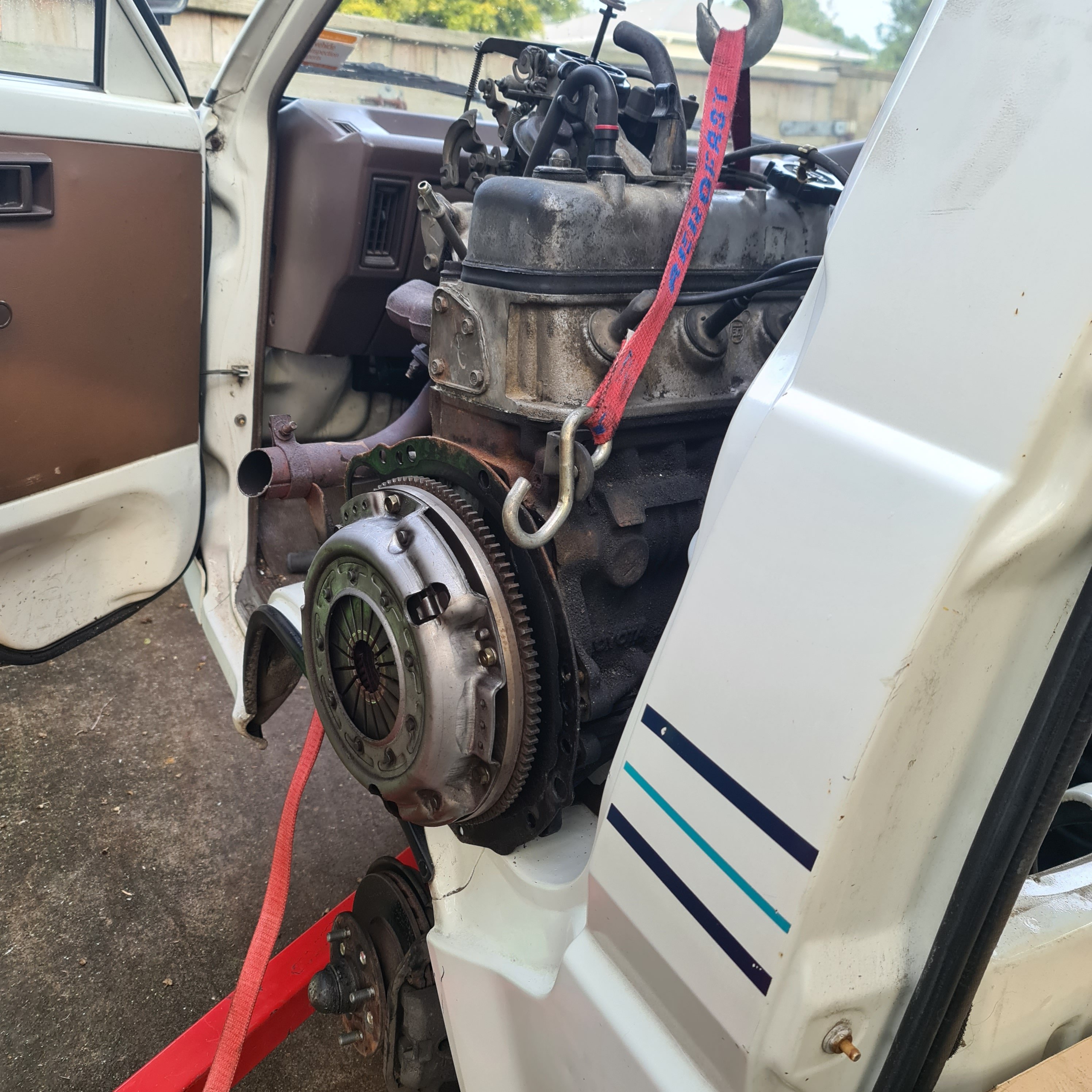
Clutch showed up today. Previously I posted the 4agze 225mm flywheel but I opted for the smaller 200mm as all the clutches were so expensive for the 225mm I used a wet piece of limited edition Freyas sourdough to remove the old crank bearing. The ae86 disc didn't fit as the spline was too small but I checked the original 5k disc and it was a next to new exedy also so a quick swap over which I then saw I could have just used the whole van pressure plate also. Oh well.
1 point
-
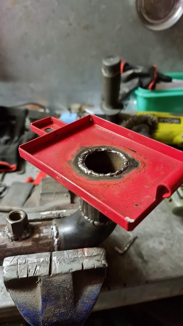
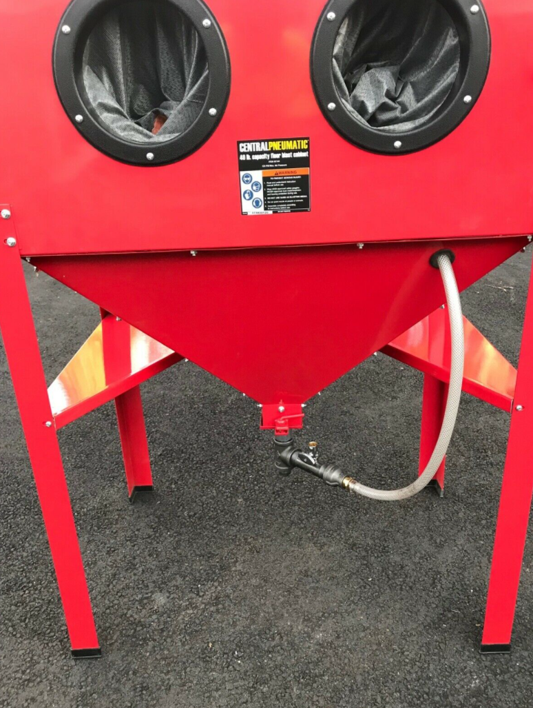
I bought a cabinet a little while ago from Machinery Warehouse. Slightly different design but probably made in the same place: I found that the pick up tube is terrible, its just useless. Any pressure from 50psi to 120psi and a big air tank, it just barely works. I tried all sorts but it just wasn't very good at picking up the media. So I modified it like this so the sand pick up is from the bottom trap door, using 40mm steam pipe and some 19mm heater hose back to the gun through a hole drilled in the side of the cabinet. Got the idea from these 'metering valve' kits people sell to do exactly this: It was made from what ever I had available to test the idea, that nut welded on the top had a ball valve tap on it but it was too small to let enough air in. Works great without the valve. Now it works awesome, constant flow of garnet. Now its actually fun to use and not constant frustration. I do still occasionally have the gun getting clogged so just cover the outlet and let the air bast backwards through the feed tube and then its good again. I'm currently fixing up a ST202 Celica, some parts could fit in the cabinet:
1 point
-
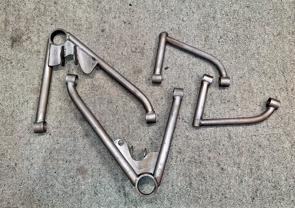
I let these suspension arms sit around so long that they went rusty and the NDT place disappeared. Now I've cleaned them up and will get them tested by SGS 'real soon'
1 point
-
I've been running one of those Carter fuel pumps on my Mercury for a few years now. It's located under the car buy the fuel tank. I don't here it when the car is running, but it is fairly noticeable when its on without the engine going. It's been fine. After getting it new I picked up a spare for $20 at a swap meet to keep in the trunk, but I haven't needed it yet.1 point
-
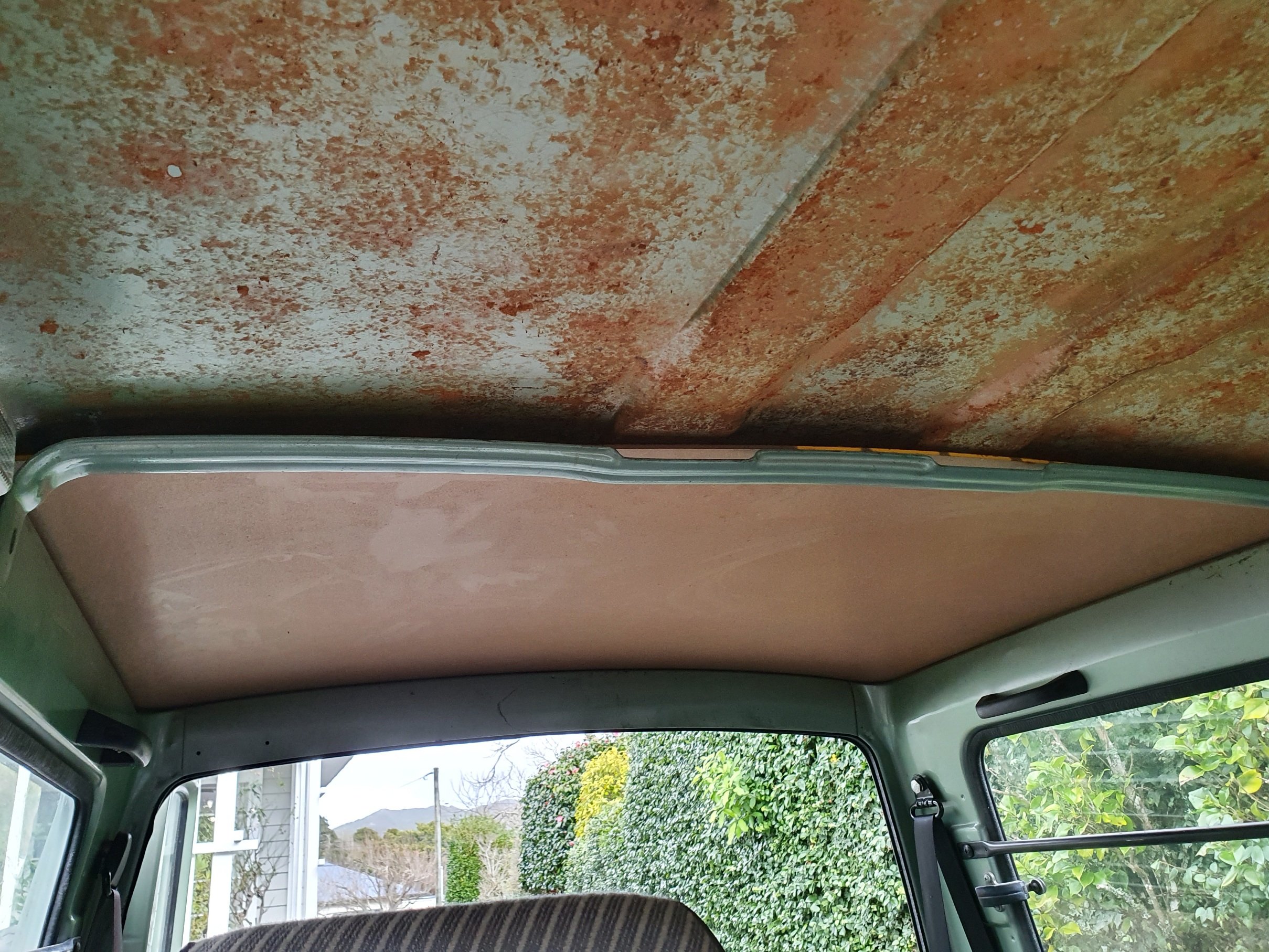
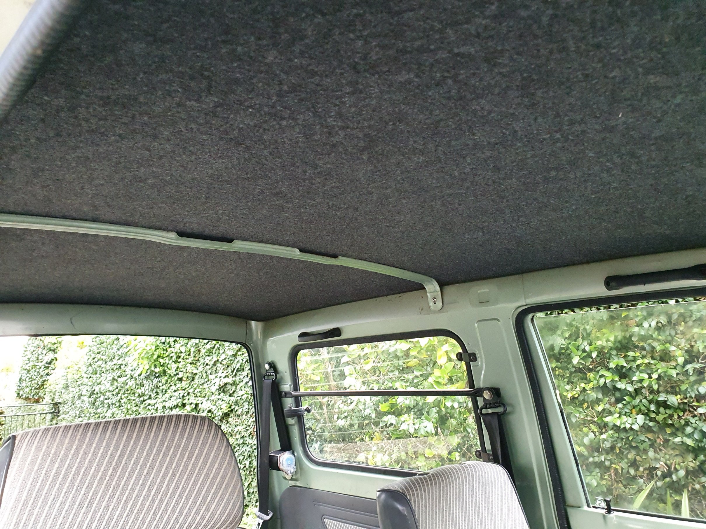
I cut the hardboard to size splitting it in two to allow me to tuck it into the roof gap. The cross brace could then be used to cover the seam between the two pieces. I used some ados ultra strength spray adhesive to glue the felt onto the hardwood and tucked it around the sides before sliding it back into place. Really pleased with the result, big improvement over what I had and only cost $70 in materials.
1 point
-
Finally, second time lucky, it was time to replace the old four-spoke wheel with my three-spoke. Before selling the Liftback I swapped the original wheel in and kept the three-spoke, as I knew I would want it in the Carib. I like how it looks and feels. A few weeks ago I actually tried to install the wheel but fell short due to the airbag connector on the clock spring being completely different. The Liftback/three-spoke has this style Which is completely different to what's in the Carib I gave up that night and just refit the standard wheel. I had a plan though; swap the clock spring with one that has the right connector. A few days later a trip to Pick A Part sorted me out with a clock spring from an AE112R liftback like my old one, which since the wheel worked on my car, it should work with that one too. Before starting the job of fitting the wheel again, I had a stitch on cover show up. I had previously used one of these on the MX5 and liked how it felt. This one was better quality and designed to fit a bit nicer than that one. After a couple of hours with a needle and thread, this is what I had. It's not perfect, but a damn sight better than the old worn leather. To fit the wheel I started by removing the old wheel and the shrouds on the column. One screw underneath, and two on the front behind the steering wheel sees the shrouds off. The top one was stuck, but I could work around it without removing it completely. There is a hidden screw for the top shroud near the ignition barrel The clockspring is held in place with four little screws, and two plugs (the black and yellow ones in the photo above). The yellow plug has a retaining clip over it which has to be disengaged first. Before fitting the replacement clockspring (unless it's new and locked) it MUST be centered, otherwise you risk breaking it the first time you turn the wheel to lock. The big yellow sticker on the clockspring says how many turns end to end it has, and to gently turn it to the left until it stops and then turn it back the other way half of the amount of full turns it has. In my case mine has 5 turns end to end, so I rotated it to the stop, and then 2.5 turns will mean it's in the center. If you have done this right the arrow on the sticker and the arrow on the housing should line up. Now you can fit it to the column. The new wheel simply slips on the splines, the nut is tightened, everything plugged in and the airbag fitted. Everything plugged in as it should. I did grab the horn connector with the replacement clock spring as that was different on the old wheel too. And it looks great! The airbag light is off, and the horn works. Great success. Of course, since the battery was disconnected I had to take the car for a spin, just to help the ECU learn again. The wheel feels great in the hand, with a slightly thicker rim now, and the better shape and smaller diameter over the old four-spoke wheel really helps make the car feel sportier. A job that was harder than it needed to be, but in the end well worth the wait.1 point
-
One thing that bugged me since I got the Carib was that the ignition barrel had been damaged, both making it hard to accurately insert the key, and making it look somewhat dodgy. I haven't mentioned this previously, because I wanted to fix it before I bought it to attention, just in case it made it easier to steal. It didn't look particularly good and my WOF guy had a good laugh when asking me where the rest of the barrel went. As part of other work I was doing on the car, I had the column shrouds off so took this chance to fix it. I had previously picked up a replacement barrel from Pick A Part (which was a pain in its self due to having to find a car with a suitable barrel, that they had the key for). With the shrouds off, it's just a matter of inserting the key and turning it to ACC, pressing the button on the underside of the barrel and gently pulling on the key which will remove the barrel. The button cannot be pressed without the correct key inserted and turned to ACC. I was then left with the pair of barrels. Thankfully I just needed the main tumbler, since the housings were slightly different. Replacement on the left, original on the right. The original has a smaller face to accommodate the illumination ring, which I guess the poverty pack Sprinter I got the replacement from didn't have. You can see the tumbler is well recessed in the barrel of the old one, with the wafers visible I didn't realise until now that the ignition lock had not been working. There is a lever on the top of the barrel that triggers it when the key is removed. Steering lock engaged Steering lock disengaged This had been disabled in the old barrel by bending back the tab that actuates the lever. This was an issue for two reasons. First, I couldn't withdraw the tumbler as normally you lift the tab with the lever to give clearance, and mine was jammed down. Second, It wouldn't work with the replacement tumbler as it is. Careful use of a small spanner looped over it had a gently bent back into place. Once the circlip on the back was removed, this allowed me to remove the tumbler. You do not need the correct key to remove the tumbler, so my key worked to remove both. You can see how much of the tumbler is missing in the above photo. I suspect someone tried to steal the car and broke the end off as it is sheared off, not cut off. With both barrels side by side, it was just a matter of carefully removing the wafers from the replacement tumbler with fine needle-nose pliers, leaving the springs in place You can see the third wafer is made up of two pieces. This is what is called a split wafer, and as long as it works it's fine, but they're well known to fail and jam, stopping the lock from working and causing a whole lot of issues to fix it. The general advice is to remove them and leave them out. There are enough standard wafers to keep the lock secure. So with all the replacement tumblers wafers removed, I carefully moved the original wafers to the replacement tumbler. Refitting into the same position is crucial, and make sure you do not let the wafers drop out when handling the tumbler. The damaged tumbler was actually missing a whole wafer as it had broken through the slot the wafer sits in. Some trial and error found one of the spares from the replacement tumbler a perfect fit, so that was fitted. The tumbler was then refitted to the barrel, and it works perfectly. Even the steering lock arm is working as it should. And refitted to the car. Much better. That was quite an easy job at the end of the day, just a pain you need the steering wheel off to remove the shrouds.1 point
-
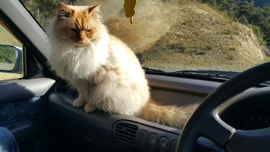
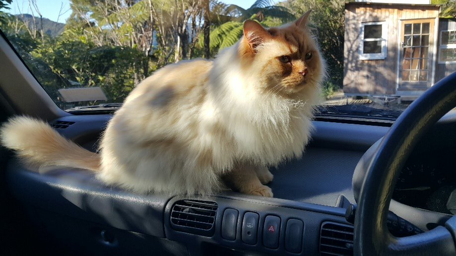
Update coming soon. However it appears that kevin has decided he likes pre-facelift cars the most. We've also now worked out that pfl actually stands for 'perfect feline ledge'. Luckily for kevin we will be converting minky to a full pfl interior.
1 point
-
Far out! November last year was the last time I had tinkered away on this project. Time flies!!! Well both Hannah and I have been pretty busy with various things like having to get the housetruck finished off and road legal for sale and with that gone we had to build a place to live. The mezzanine build took a fair whack of time. That's all pretty much done, well at least to a point that we can happily live up there. I started losing a feel for time over summer with all that going on. Then a Micra/March turned up. A simple, cheap run about while the Imp is off the road eh. Then another Micra... and another. Oh - so now these are projects are they? FFS. Oh hey...what's that? Is that a Bedford TK truck in the yard. But hang on.. you've already got 4 other vehicles to play with, not to mention the old 4wd Hiace van that's getting bit rusty around the edges. Well screw all them. I just needed to get my 'flat six fix' so I dug out all the bits that had been hibernating under the bench and had some fun piecing them together in a sort of organised fashion on the table... Now where does this bit go?.... After having some fun taking photos I stashed some of the parts like the heads, cam gear, pistons etc that I wont need for a while back under the bench until needed. I had to confront a mini stumbling block I had with the oil pump drive sprockets. There is one small sprocket that slides onto the hub of a larger one and needed to be fixed in place. My initial thoughts were to weld it but I was worried that it would warp and cup. I sized it up for possibly bolting it in place using small cap screws but there just wasn't enough room between the chain and the hub, even for small 4mm screws. Welding it was going to have to be. I would get some advice though beforehand. But first I wanted to add a very slight taper to the teeth so there would be no sharp square edges that could potentially catch and rub against the inside of the chain plates. 3 of the sprockets were easy enough to pop in the lathe and give them a tickle with a flap disc. But the smallest I had to whip up a little hub to clamp it on... Trying to take a photo with one hand while holding an angle grinder in the other... Then sitting in front of the fire and cleaning off any sharp edges... Now I had sprockets I was happy with I had to confront my welding issue. I popped over the hill and chatted to another engineer I know who has a lot more experience with welding of such things than me. He pretty much told me what I had already guessed and I decided to just go for it. But just to be sure I thought it prudent to machine up a fake sprocket and hub to see how they faired when welded. There was no cupping evident so I went ahead with the sprocket. First thing though was to heat both parts up gently. Not too hot. Just hot enough that I could touch them but not get burnt... This way the welding could be quick and light without a mass of steel sucking the heat. But not so hot that shrinkage could be an issue either. I used the little tig welding table I had built ages ago for more comfort when doing such jobs... I'm certainly not a super neat tig welder like some artists out there (and never will be with only having decent sight out of one eye so judging the distance can be an issue) so I was very happy with the result and super happy that nothing pulled.. With this part finished I could concentrate on the chain tensioner design. I had a few ideas and had amassed a few bits to tinker with.... Being that the chains are under constant load and only turning a pump the tensioners are really only needed to stop excessive slap. Nothing to do with timing changes like a cam chain. I had two Datsun A12 tensioners to try out but no matter how I arranged them they conflicted with each other and there was no room for mounting bolts where I needed them.. So I tried out some Mazda/ford 2.0 duratec tensioners and they show great promise... I will make mounting blocks to suit and knock this part of the build on the head! Then onto finishing the bellhousing Hopefully some more updates soon although we have also started pulling one of the Micras down for the big swapsie game but that is mainly Hannah's project so I can keep working on this as I can.1 point
-
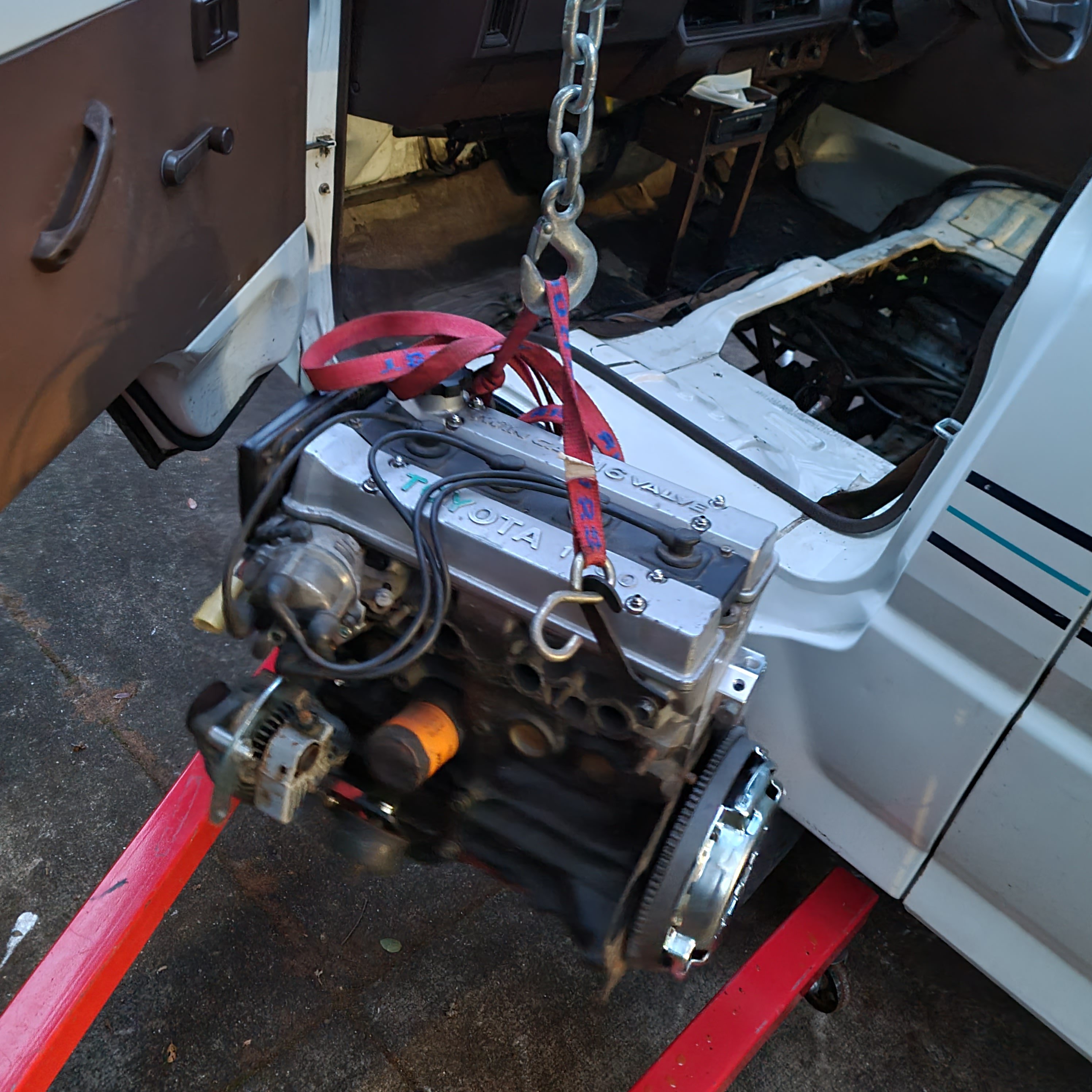
Lift van up and take passenger wheel off to slide crane in then it was pretty straight forward
1 point
-
I can see! I just had a look on Google at your work. Very impressive. You have a very talanted and keen looking bunch of team mates. You look so proud!...
1 point
-
It's been a long while since the last post and I don't feel like I've done enough for a full post yet, but I do want to put something up to show what I've been working on and to say that neither me nor the project is dead yet. I had typed out a nice post but then the browser crashed and I lost all of it so this might be a bit less polished than usual as I try to rush it out. I carried on from the driver's side guard lip by doing the same to the passenger's side. It didn't take long to get the lip cut out and the new one tacked in. You've seen this all before so I shan't write too much about it. No sooner had I tacked it in, that half the bloody car fell off in my lap! I let myself be convinced by those less directly invested that this would be the best way to tackle the whole thing. To be clear, I agree with them, but damn is it not confronting to see it on the floor like that. This way I can get good access to properly panel beat all the welds, as well and ensure all the inaccessible cavities are properly sealed up and corrosion protected before I put it all back together. For example, see here the bare metal and (house) paint flaking off the inside of the lower window panel. I can paint this up properly and have total piece of mind when I weld the quarter panel back on. You can see also how much better access I have to cleaning up the weld on the wheel tub as well. With the quarter off, I had a nice easy down hand weld to get the arch final welded, then I stripped the panel inside and out. I then spend the next 50 hours panel beating the lower rear corner to clean up the patch welds and sharpen up the body lines that run back from the rear of the wheel arch. It's sitting with a guide coat at the moment so it looks far more wavy than it is. The welds themselves are pretty hard to spot at this stage if you didn't know they're there. I'm not very good at it but I'm enjoying the process. I still have the whole of wheel arch weld itself to handle as well, hence not feeling like enough progress to warrant a full post. Hopefully by the next post I'll have it welded back on the car and looking straight as an arrow. Here's wishing everyone a happy new year since it will likely be after that at this stage. Cheers.1 point
-
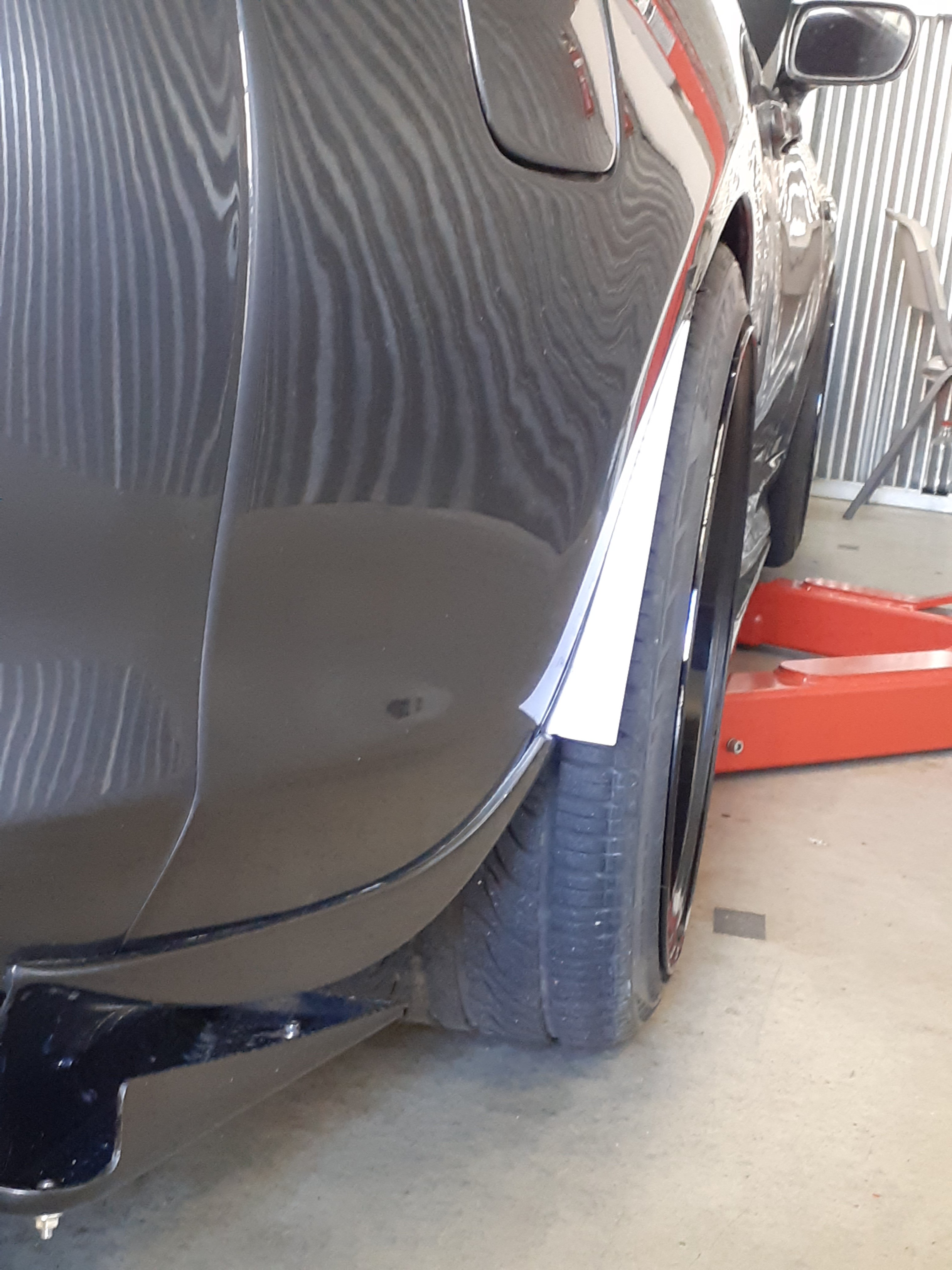
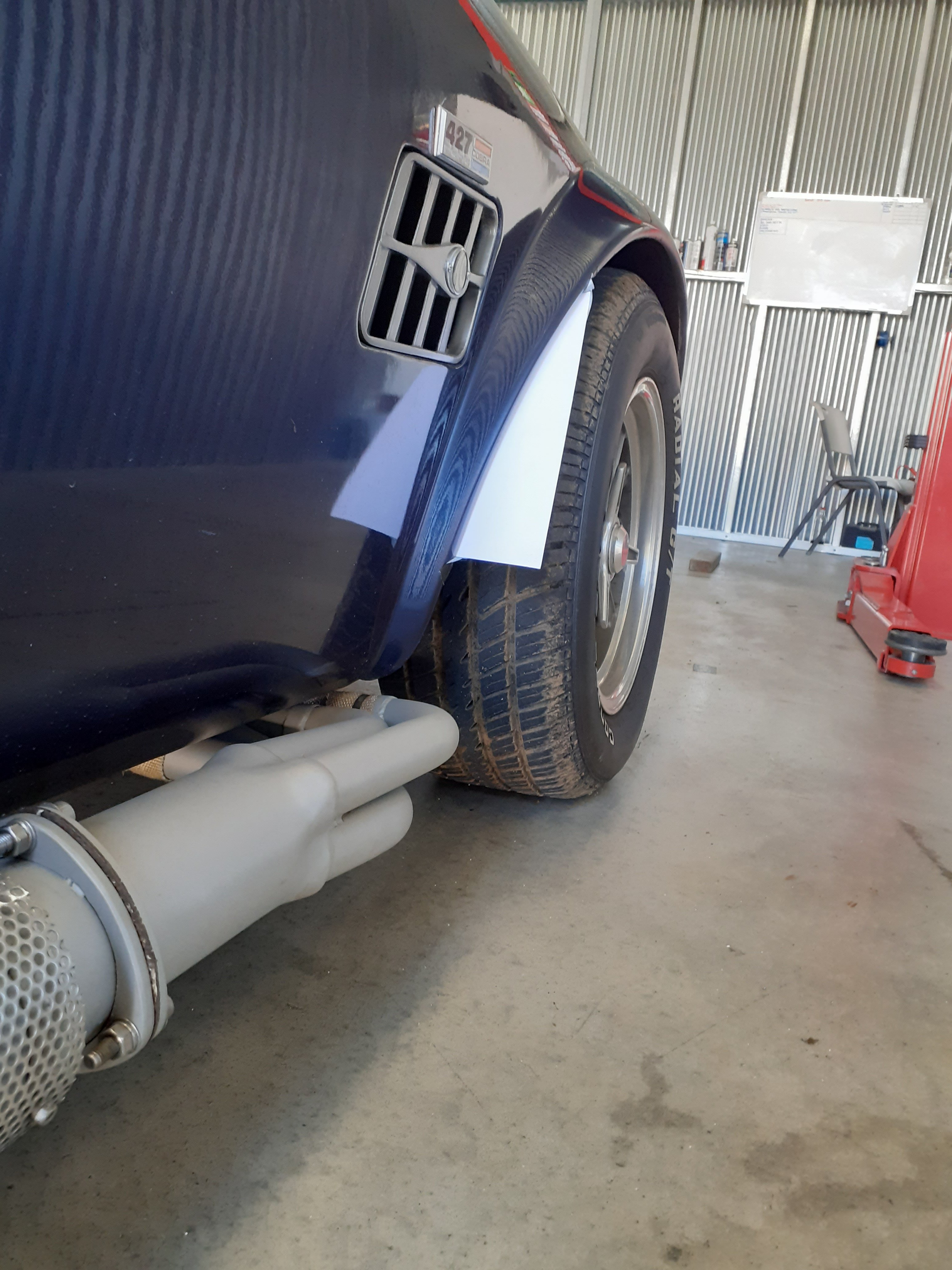
mudflap dimensions gunna be written on cert plate?1 point
-
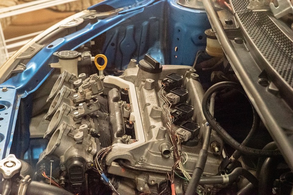
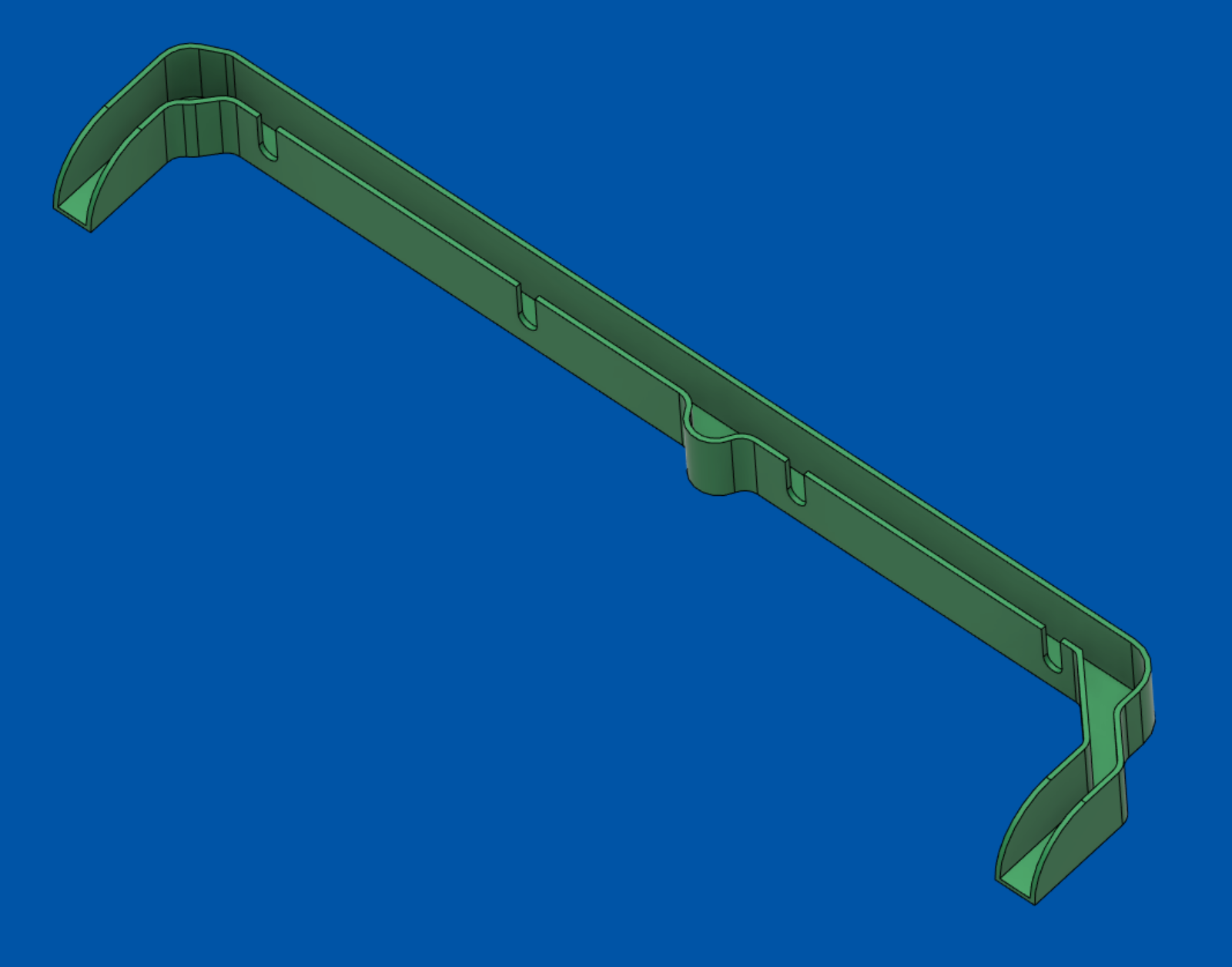
I've been printing some proper trumpets from HIPS material but they take about a day each. Currently two done, two to go. So no more glow in the dark PLA... Since I'm definitely not ever going to use the standard ECU anymore I've also been tidying up the loom a bit on both sides of the firewall. Chopped out a whole bunch of crap that doesnt need to be there anymore. Also put in my EarthX battery so thats about 8kg lighter from memory. On the whole I think I'm gonna try make the engine bay look tidy as best I can, and hopefully the lessons from this will flow on to future projects. I bought some Rays Engineering GR-N wheels which look beaten up to shit. But should come up alright and were a good price. Theyre still cast wheels but even so, are a little over half the weight of the ROH wheels haha. Currently in Carterton so if anyone's down that way and coming up to Waikato, let me know if you are keen on some $$$ to deliver some wheels! I've decided that even if I try do a fancy loom it's still going to look very busy with shit draped everywhere. Because there's just a lot going on. So a much easier solution that suits my lack of wiring skills is to make some cable trays that hid everything. This way it's easy to modify later if I want to add extra wiring, and still gives some good mechanical protection etc. So starting on the injector area and will run the VVTI solenoid wires through here too. It will have a top cover piece. But you get the idea. Will do the same for the other main wiring paths along the engine. I want it to hug the contours of the head as best possible, and be as slim/short as possible so it's still a few iterations from finished. Also at some point I will print another manifold that flips the throttles the other way up, so it hides the throttle cable arrangement a bit better.
1 point
-
I had a couple of cars in today so put cardboard on them where a flap would be required under the proposed rule
1 point
-
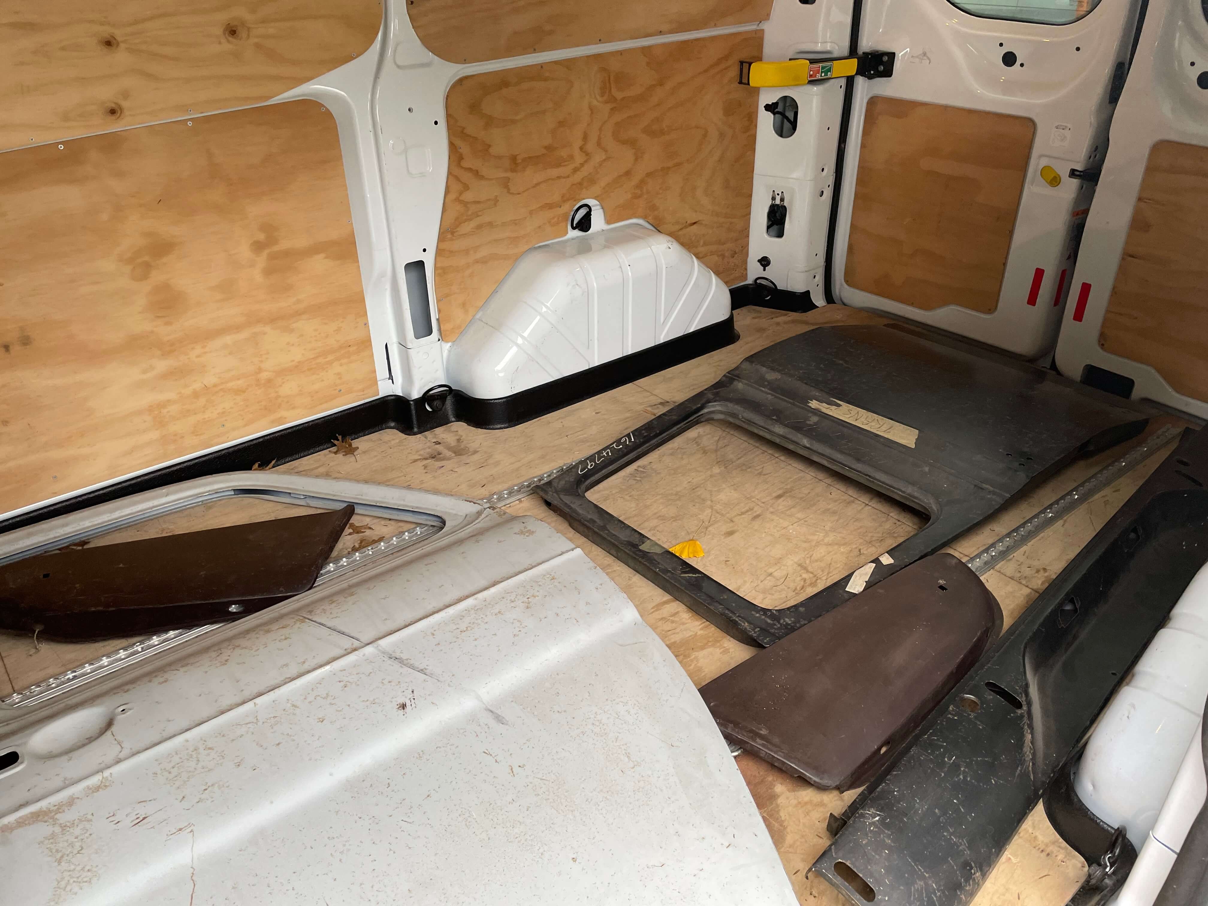
And fast forward to yesterday, I stripped out the interior, loaded up the van with some NOS panels from my "stock", Loaded in the trailer and took it to my panel guy who did the Mk1 for me - exciting!
1 point
-
Unboxed the lower quarter piece to test fit. Not too bad but I think the B-pillar needs some persuasion. I'm going to make a pattern off the good car for a comparison (although I don't know for sue if that is exactly right either). This wood stuff seems easier than making steel skins up though
1 point
-
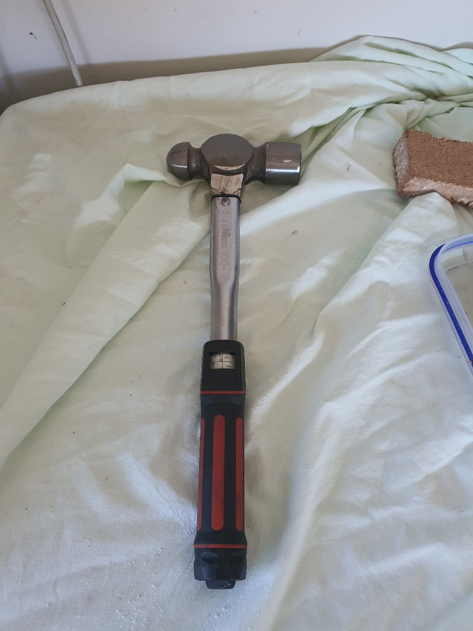
Built this for an old workmate who absolutely is the epitome of "everything is a hammer" so much so all torque wrenches got referred to as torque hammers on site. It still functions and will dampen shock if you adjust it down , pretty cool kind of dont want to give it to him.
1 point
-
Had the SCU in work today and I asked him your question, the answer is that they typically won't pull over anyone in an area with no cell phone coverage, because it puts them at too much risk if shit goes bad, so they will typically follow at a distance to somewhere that is safer, or if there is 2 of them, they will pull you over to instruct the driver to a place where it is safer down the road. But he said, not many cops pull over modified cars because they are modified, they simply don't have time for the paperwork, they are nearly always pulled over because they are speeding or being a dickhead on the road and the modified side only becomes an issue where they occupants are failing the attitude test or there is obvious safety or public annoyance issues.1 point
-
Did a thing, it goes broom broom. Huge thanks to @GuyWithAviators and @Geophy. Still needs a fair bit of love but it runs and drives and makes all the right noises so that's progress
1 point
-
Ooooh its been over two months since I updated this thread. I have not touched this engine since stashing all the bits under the bench out of harms way, throwing a blanket over the main block on the bench and spending most of my time since then buying up many Micras, working on the housetruck and building the mezzanine floor in the shed. Oh and some of that paid work thing too because we do have a mortgage to pay. However - I still have a little bit of progress up my sleeve to report before we get up to real time. So I can do an update and hopefully soon I'll be back into working on the engine. I'm very much looking forward to moving in upstairs because I can whittle away on the project even easier. Well at least I think it'll work out like that? There's still a load of sawdust to create yet before we can move in though. So where I left off last time was in making the start of the adaptor plate/engine side of the bellhousing. I needed a flywheel to work out its depth, due in part because I am intending on using a concentric slave cylinder, one that was left over from the Ford Mundano that we had robbed ages ago for its engine to fit into the Viva wagon. I had a Subaru Leone 1800 ring gear to suit the gearbox. I needed a clutch setup to suit and started hunting a variety of places. I found a brand new subaru Leone clutch disc going cheap on trade me so I snapped that up pronto. Now a suitable pressure plate. I was just going to buy a Subaru item but had realised that it wouldn't have worked - hence my question to you all in the last update - but no one on here came forward. Someone on retro rides forum won the prize though and guessed the issue. Whilst out on a run, my head clear and thinking of things it suddenly dawned on me that the pressure plate tension straps would now be in compression due to the Hondas anti-clockwise rotation (or clockwise when looking at the pressure plate). Luckily there's loads of clutch components available for early Hondas with their anti clockwise engines and I ended up sourcing a new pressure plate from a mid 80s Honda accord/prelude that would fit the bill and suited the new subaru leone clutch disc I'd already bought. The pressure plate was cheap from Rockauto - turning up only 5 days after ordering. They always amaze me! Clutch sorted and sitting on the bench. I could now measure up and start on a flywheel. I had Dylan @ThePog draw up a cad file of what I wanted- the right diameter and pilot holes for the adaptor bolts. He suggested that I get them to leaser cut pilot holes for the pressure plate bolts while at it and this saved some time. Got my plate cut and picked it up from Dylan's - giving me another chance to marvel at his Dynafari. I first set it up and bored it out a 1/4 way through to fit perfectly onto my flywheel hub I had previously made (this hub also has the surface that the rear main seal run against)... I could then seat the flywheel onto the hub, clamp them down and drill right through into the hub. Drill out to tapping size, tap the hub holes, clearance the flywheel holes and finally countersink and spot face the flywheel holes to suit some fancy bolts I bought - these need to sit near flush with the flywheel surface to clear the clutch disc damper springs. Pics... Flywheel now bolted to its hub I set it up in the lathe for machining... Then gave it a skim. Checked it again, double checked it and then triple checked it. All good. I then machined the required step onto the face to suit the factory specs for the clutch. Next thing was to add the ring gear I add. Now this was a bit tricky because my lovely old Mitutoyo vernier calipers (one of the first tools I bought when starting my apprenticeship) were not big enough to measure that diameter. My old work place I did my time at had some lovely 600mm Mitutoyo calipers in a lovely wooden case. They were one of the treasured items of the tool room and I used to love using them. I had priced up some 600mm items from a variety of other brands but wayyyyy too expensive for me. I'll still keep looking because they'd be handy for many jobs. Might find some second hand. But that didn't help me when I wanted to do this flywheel now So I made an extension from some stainless I tigged together, replicating the end of my calipers. Taped in place securely and hey presto- I had a new updated tool. Never perfect like the real thing so I had to really triple check my measurements but managed to turn the flywheel down to give me just the right amount of interference fit I wanted from a shrink fit. Into the bench top oven the ring gear went, heated up and it dropped on to my machined step nicely. Cooled down and its not going anywhere. With that in place I rechecked it all and got the throw out on the flywheel down to about 3 or 4 thou. Super happy with that. My clutch kit now bolted on in place and I have something I can set my bellhousing depth to suit... I have added the required dowels and its all done. I'll get the flywheel, clutch and crank balanced together before assembly of the engine. So that will be the next update I think. Machining the spacers that will become part of the engine side of the bellhousing adaptor. Then I need to finish off making some chain tensioners to suit the oil pump drive chains. However I still have plenty of other jobs to do on the housetruck and the mezzanine. Those are a priority whereas this is just a fun little project. But I must mention that today whilst out on a bicycle ride we had about 50 various motorbikes pass us on part of a charity run. I spotted a bright metallic blue Goldwing 1500 go past and as it accelerated up the hill we were on it had that distinctive flat six exhaust note and just sounded superb! It certainly got me tingling and all I thought of was that sound coming from my Imp A good incentive!1 point
-
I used to have an 86 Mustang that had a bit of work done and it was a real weapon. I'll see if I can dig out the specs I had of it, but basically it had edelbrock aluminium heads, good flowing exhausts, 5 spd and 4:11 gears.1 point


This leaderboard is set to Auckland/GMT+12:00