
Leaderboard


Popular Content
Showing content with the highest reputation on 12/27/20 in all areas
-
Wife wanted a long dinning table bought a 2.4M slab of cherrry? Wood measure twice and it actually test fitted the first time! turns out it’s a bit long once we put it in the lounge..... so have cut shorter belt sanding for hours sucks, maybe 1/3 of the way there now (should of hired a floor sander) recycled some legs from scrap at work19 points
-
First job, get some bling on! Browndog's 1972 V8 Transit - Page 2 - Project Discussion - oldschool.co.nz
 17 points
 -
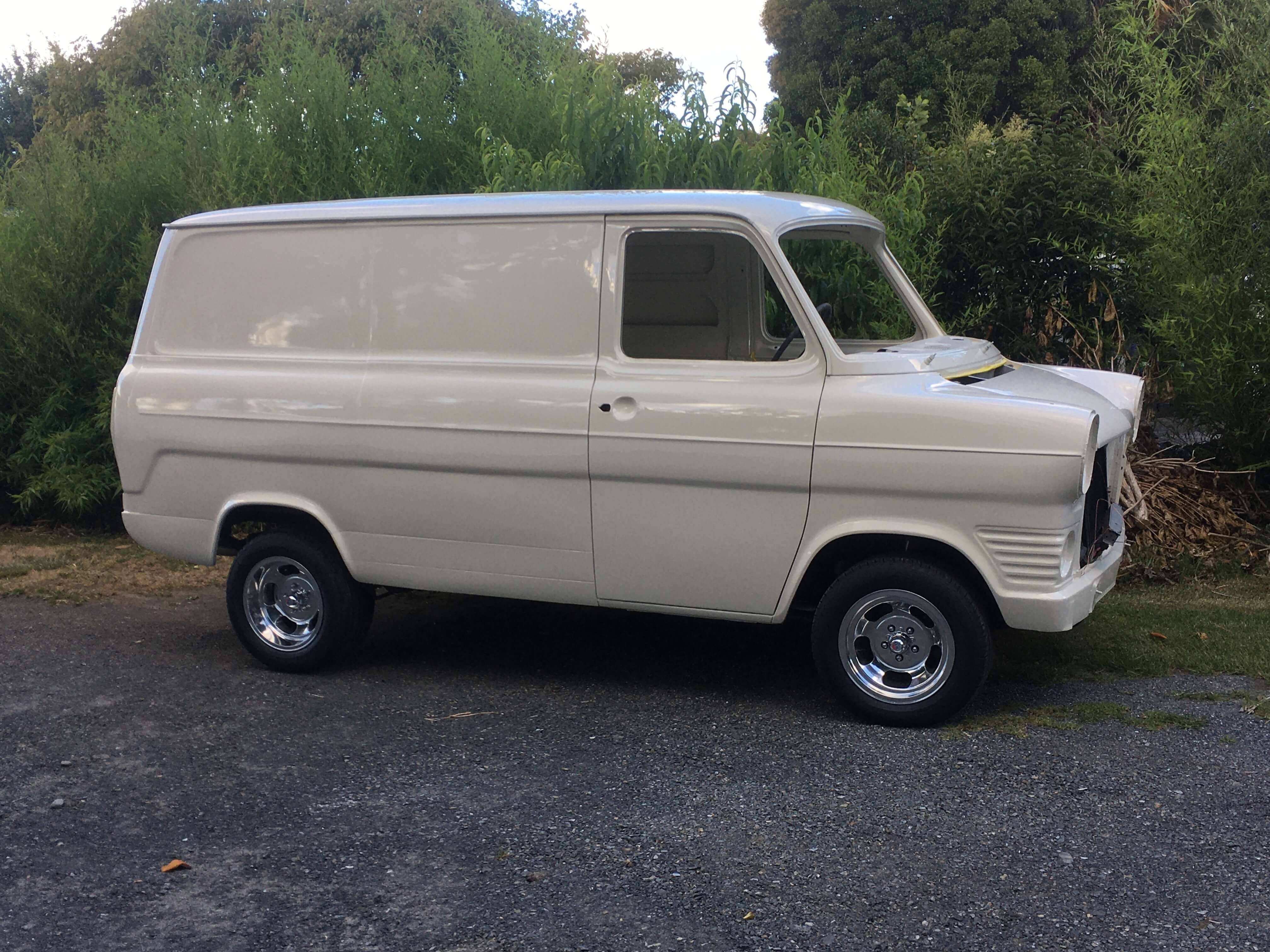
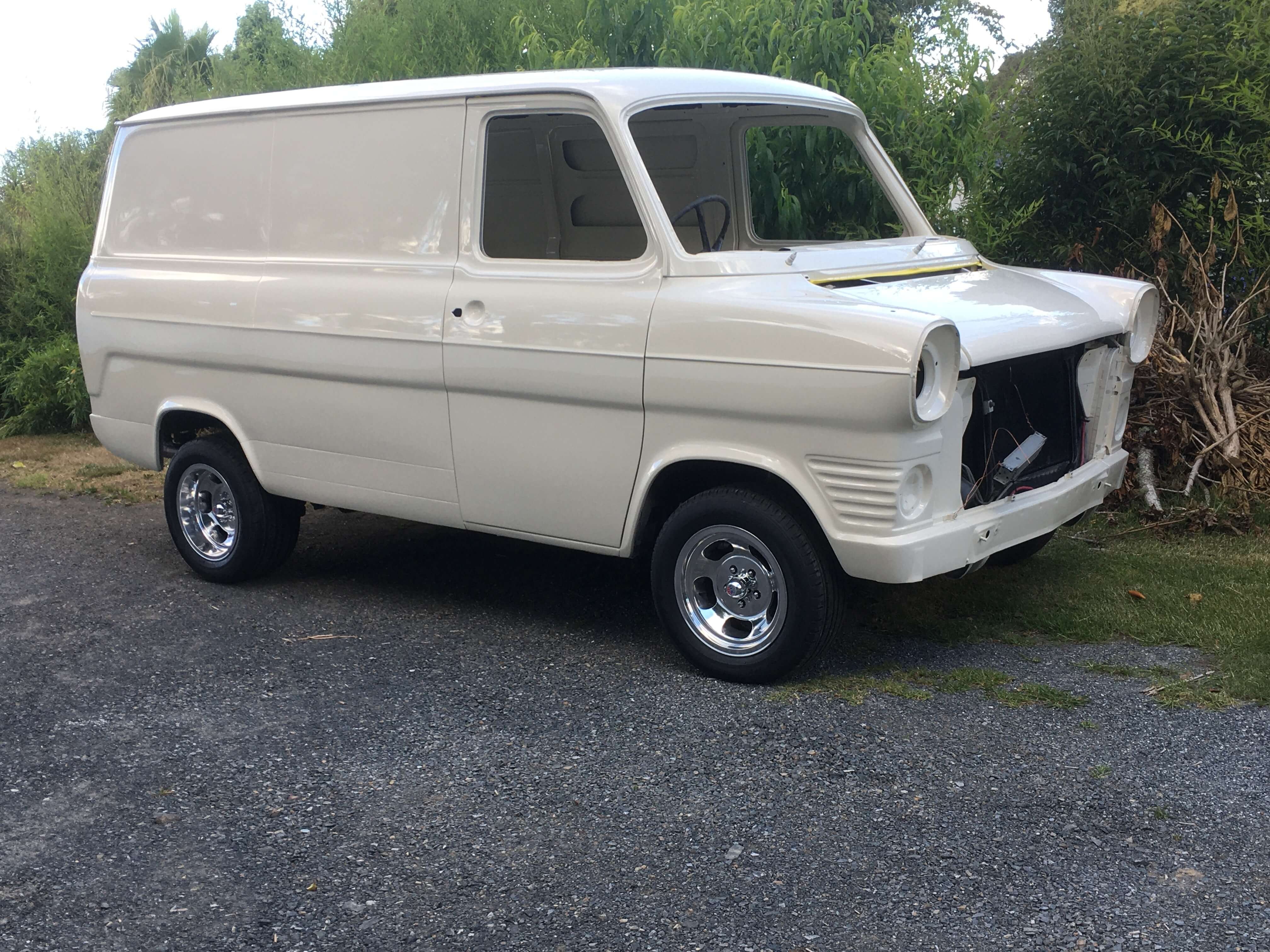
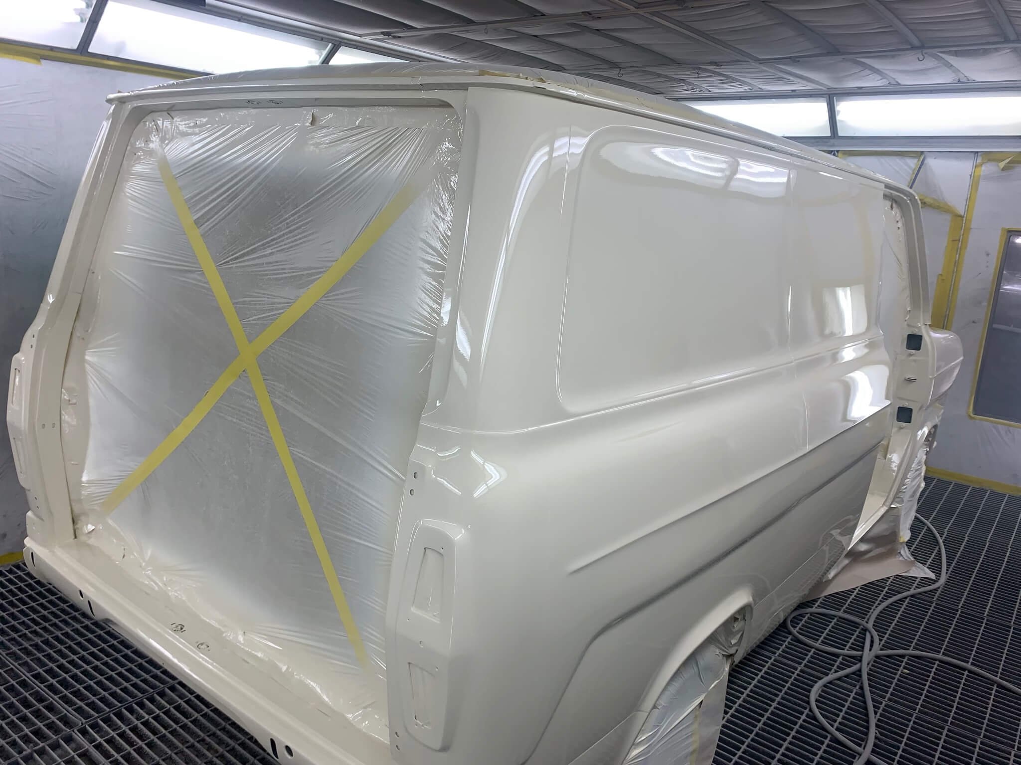
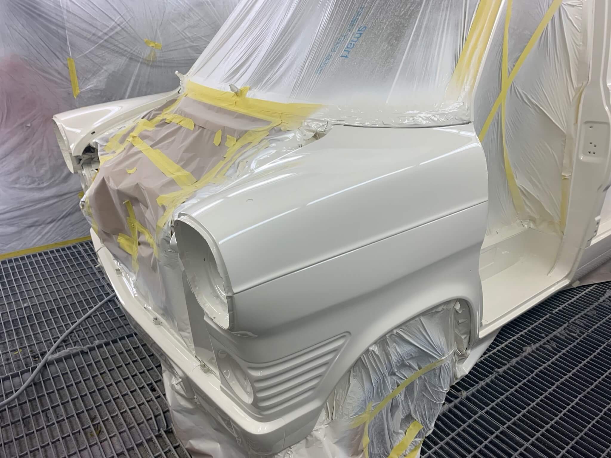
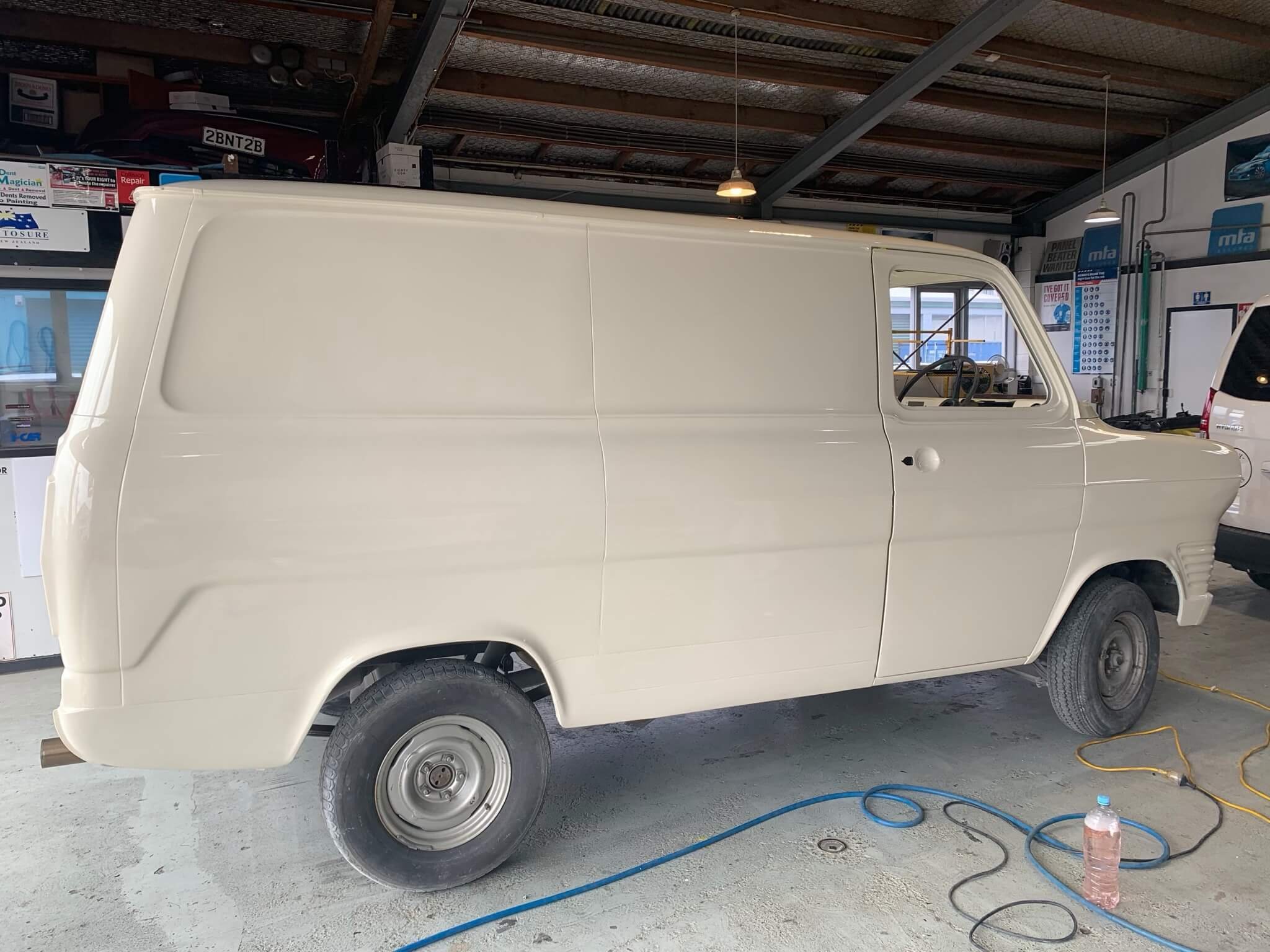
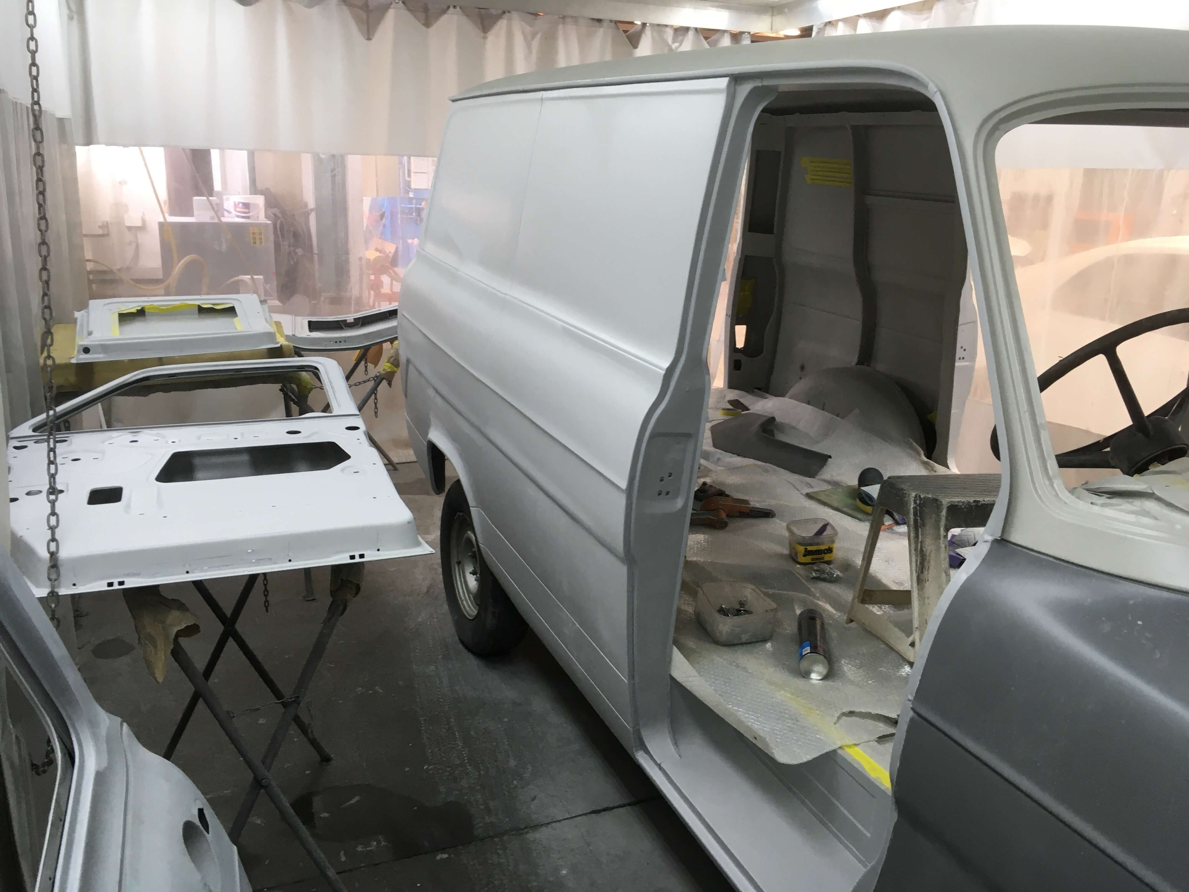
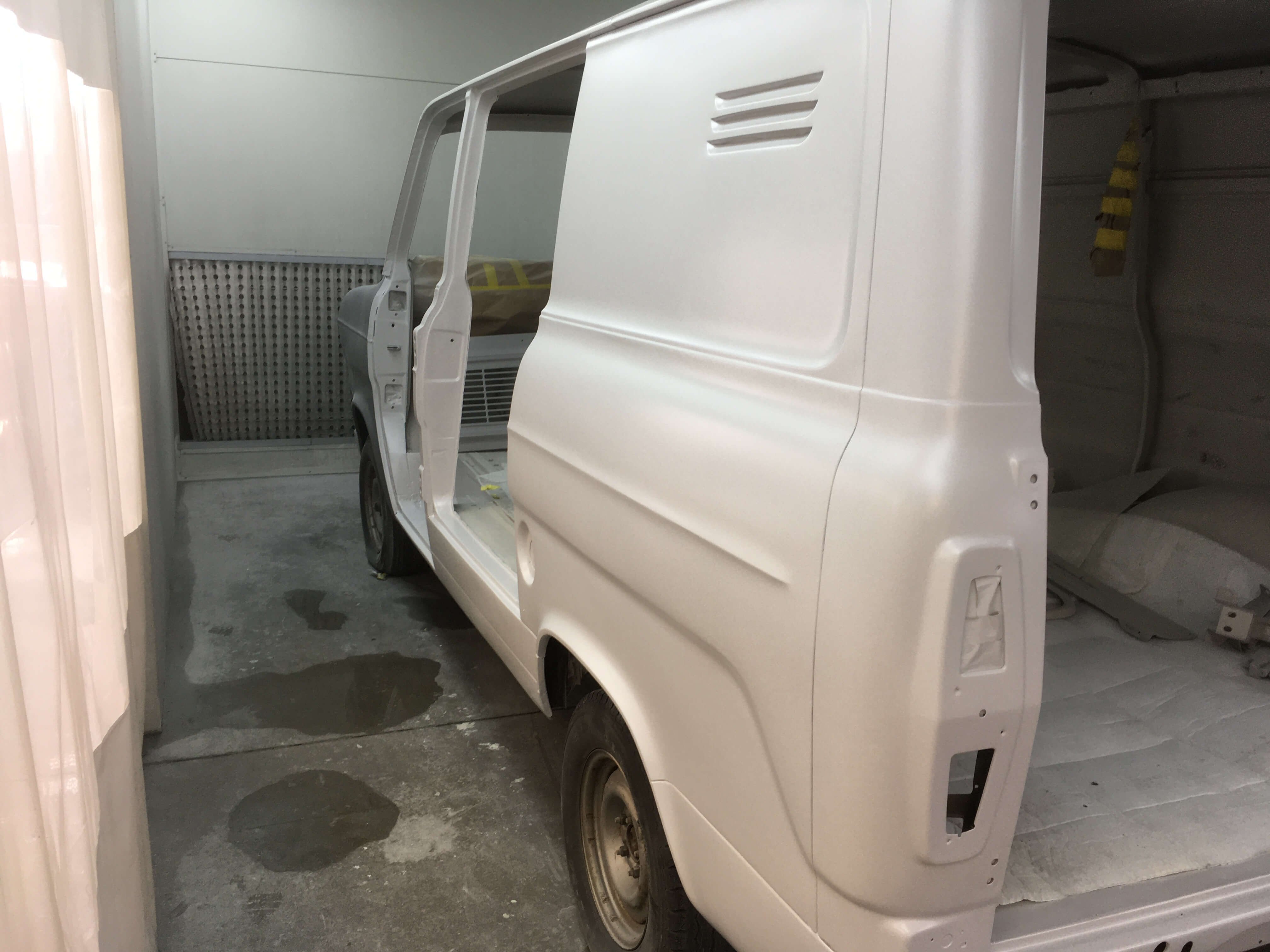
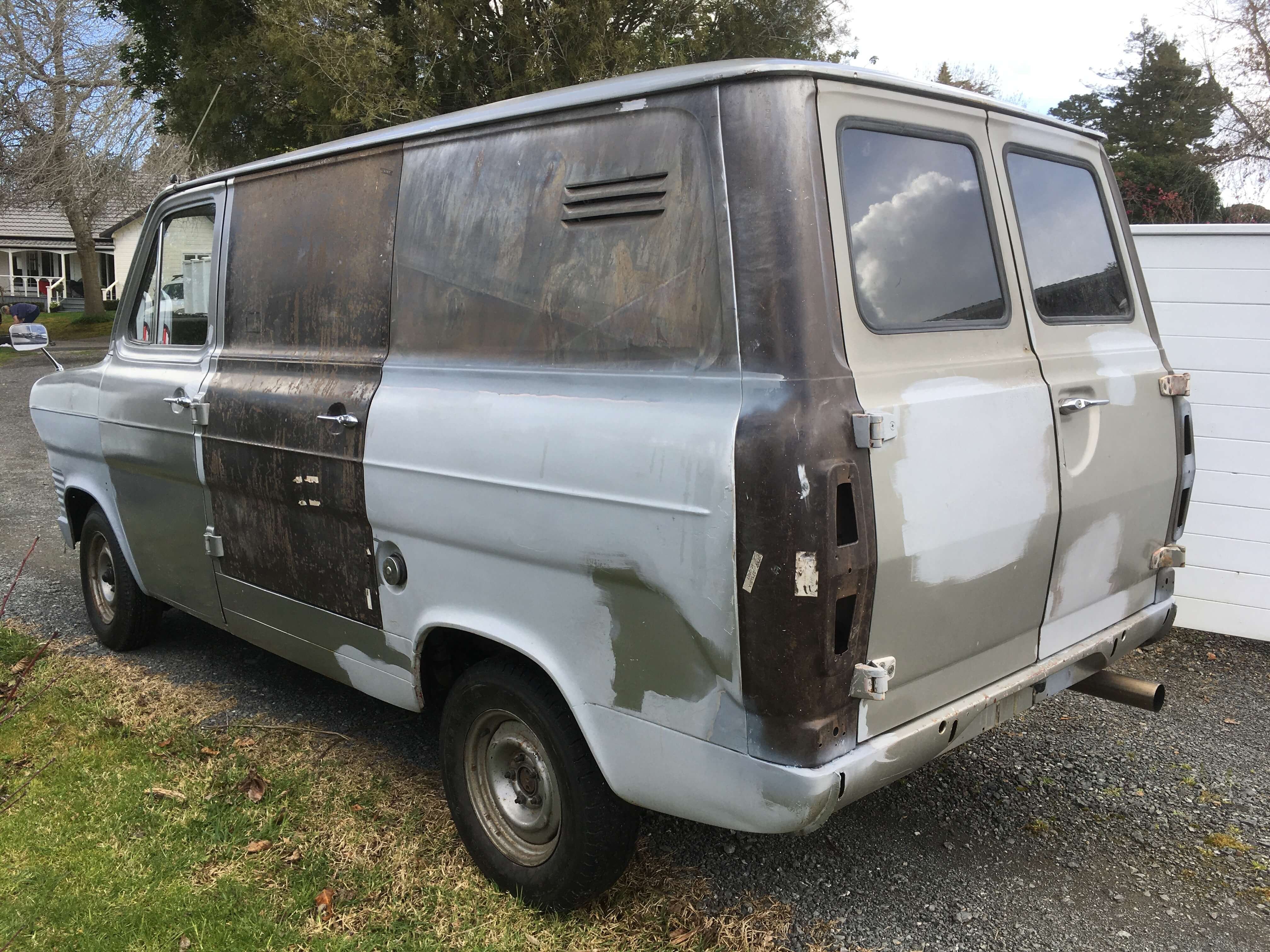
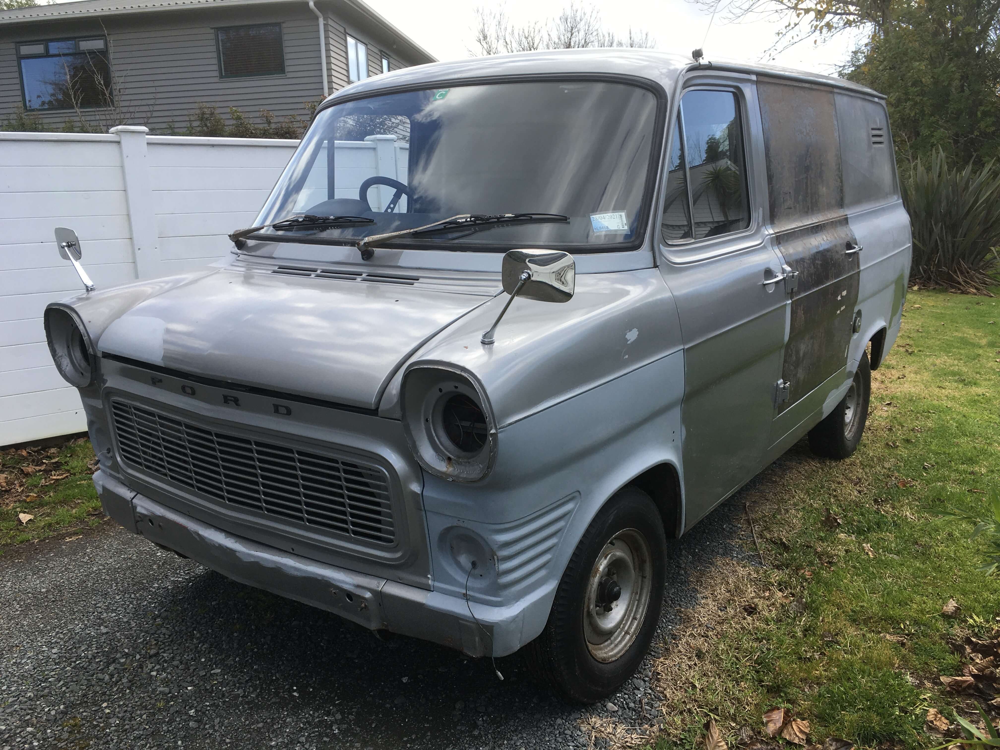
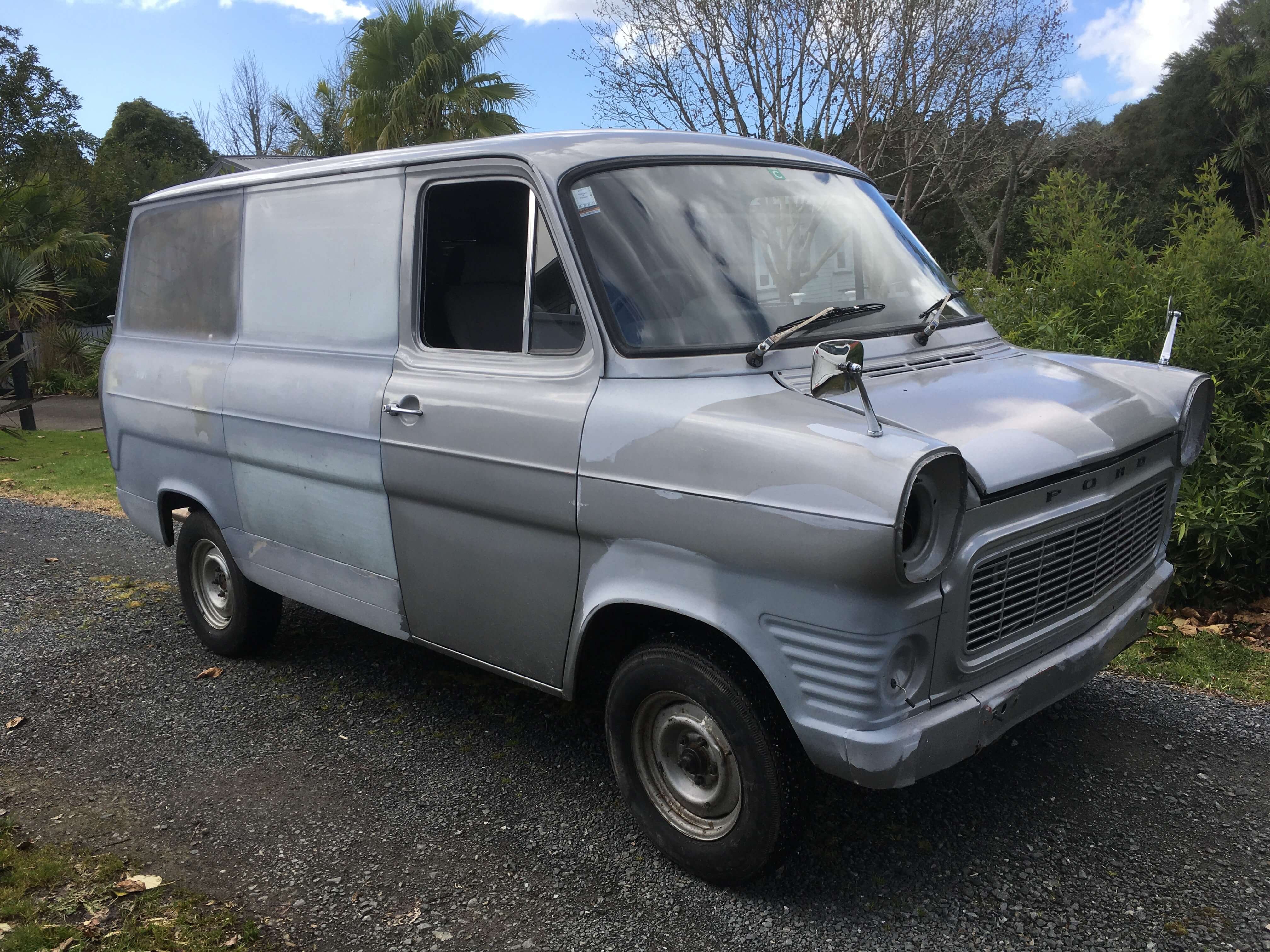
Merry Christmas everyone! I picked up my Christmas pressie on the 24th, after months of being at the paint shop. It has been painted Ford :"Ermine White" although it does appear more creamy than I think it probably should be. No matter, I am quite happy with the result, it has been many years, decades actually, since this van was one solid colour! https://oldschool.co.nz/index.php?/topic/45289-browndogs-1972-v8-transit/page/4/
14 points
-
Santa's sleigh just arrived! https://oldschool.co.nz/index.php?/topic/45289-browndogs-1972-v8-transit/page/4/
10 points
-
Made some Xmas presents for my family. Old man is dutch and this is our surname, learned a few new tricks on the esko cad machine. Dad was chuffed.
9 points
-
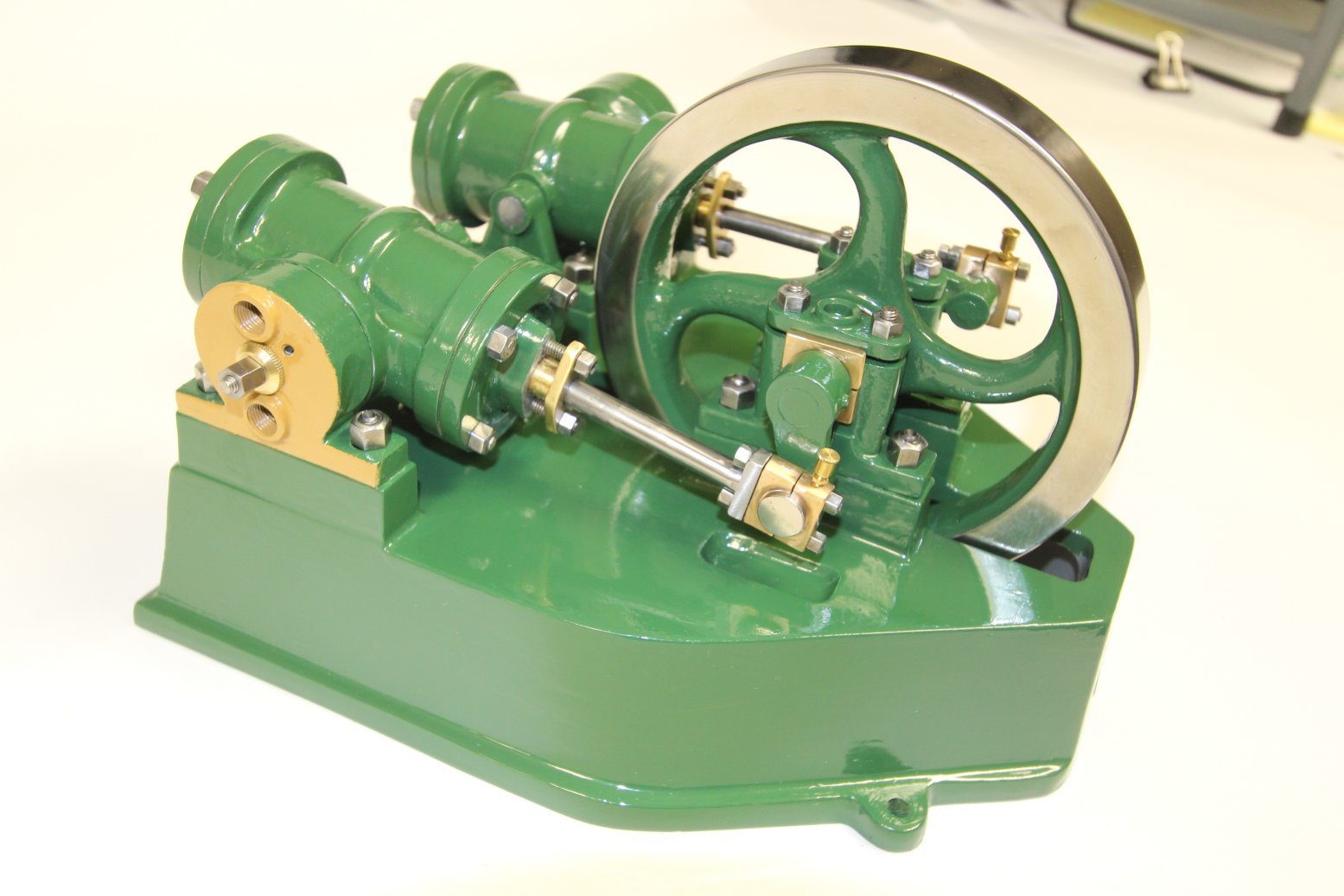
I was learning as I went, and some of the molding techniques that I use now are different, but you get the idea. At the time, I had not mastered gray iron, and so I was only able to make two flywheels in iron. The remaining parts are in 356 aluminum. These days, I can make any part in iron, no problem. Here is the finished engine that I cast. It is a 60% scale model of an engine I saw from 3 photos from the UK. 3D model was made using Solidworks. .
9 points
-
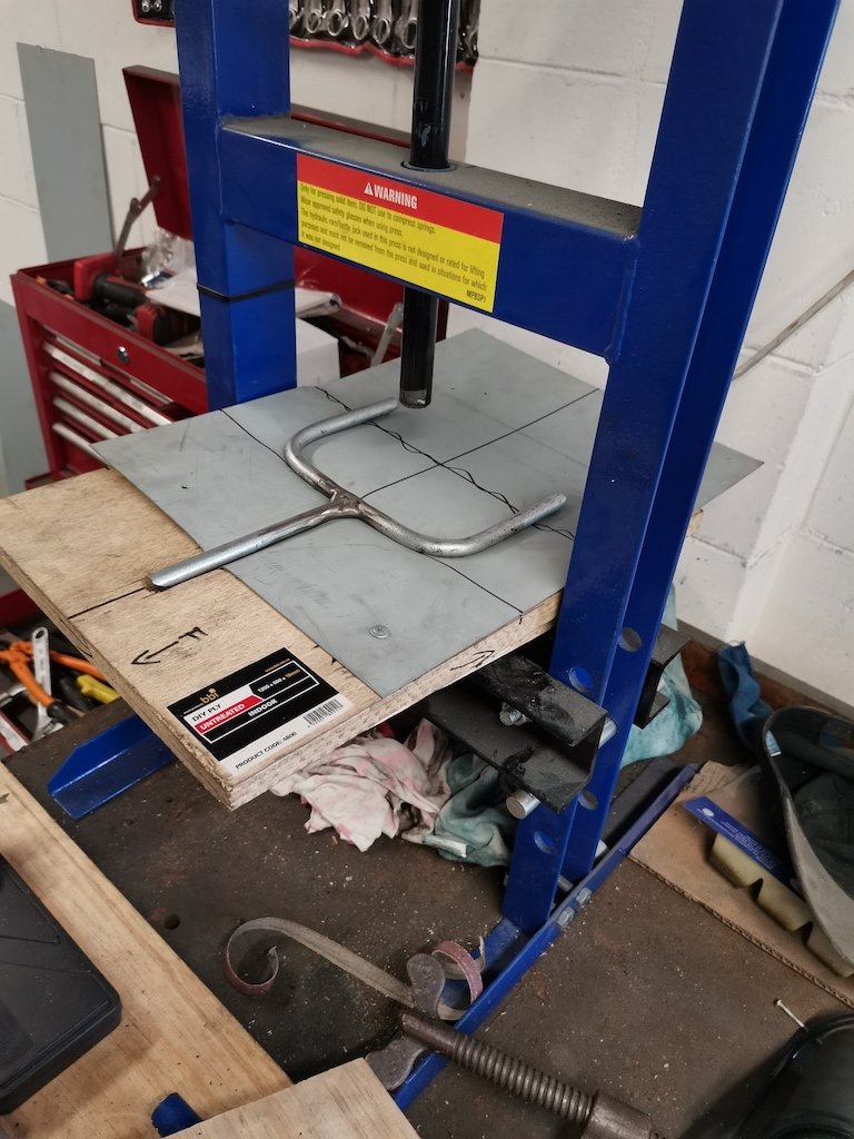
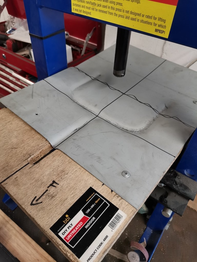
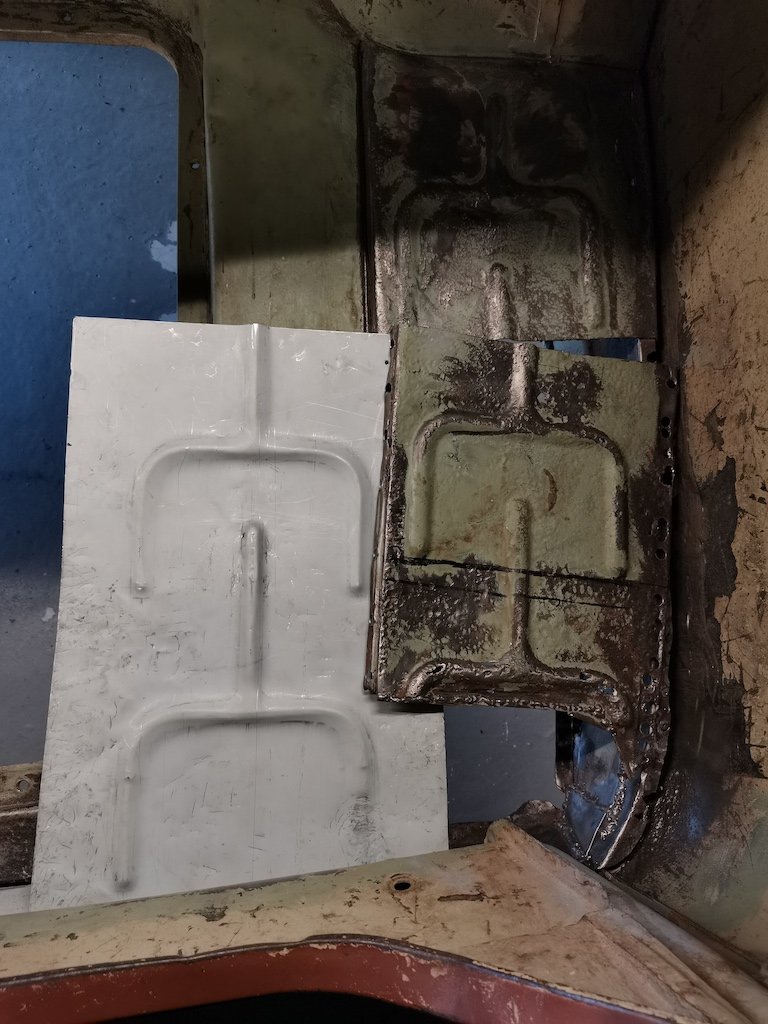
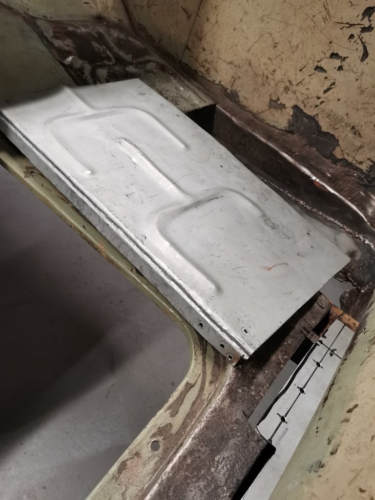
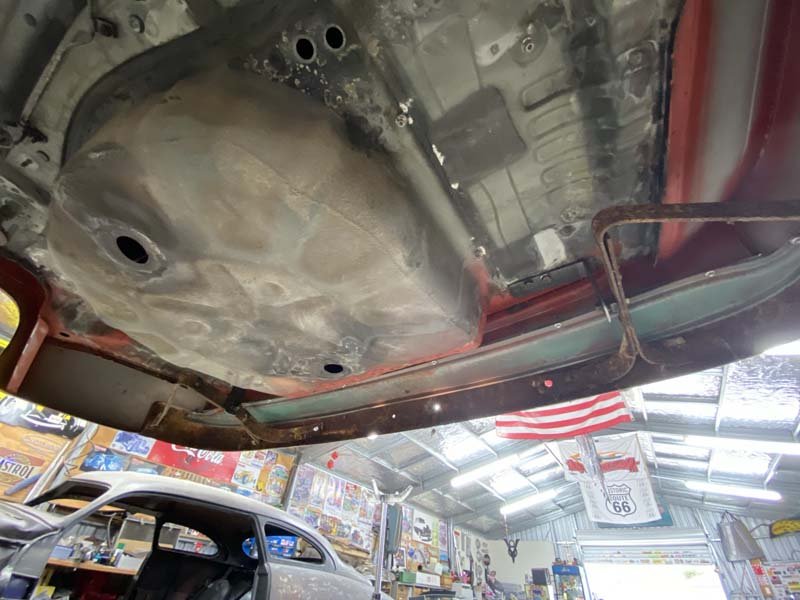
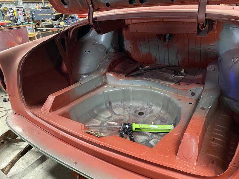
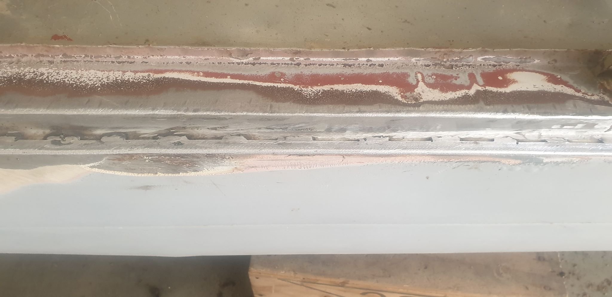
Got the spare tyre well sorted. Working on making up a patch for the boot floor. Made a template out of some rebar and plywood, used my hydraulic press to form the steel. Came up fairly well. Next step was to bend up the edge, I used two bits of EA welded together to make the basic shape, then hammered using a bit of flat bar.
8 points
-
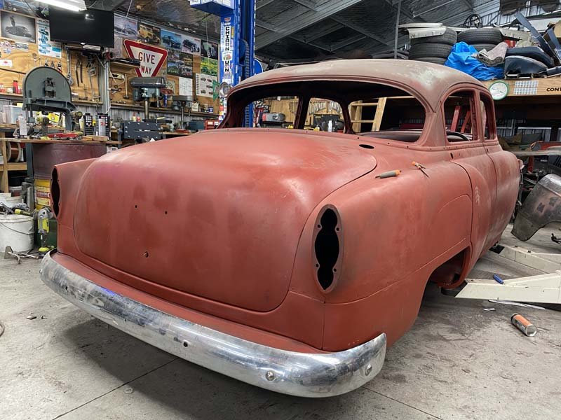
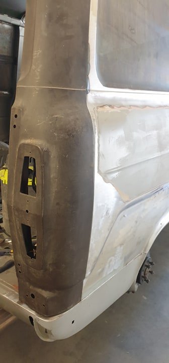
Big bum fitted
7 points
-
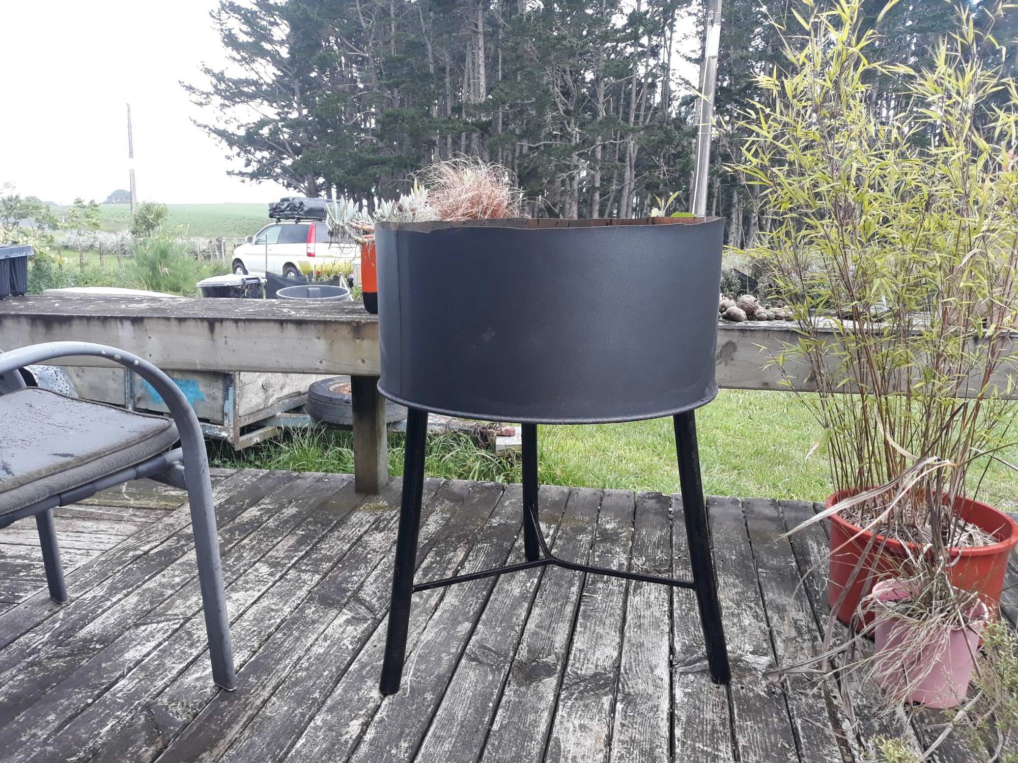
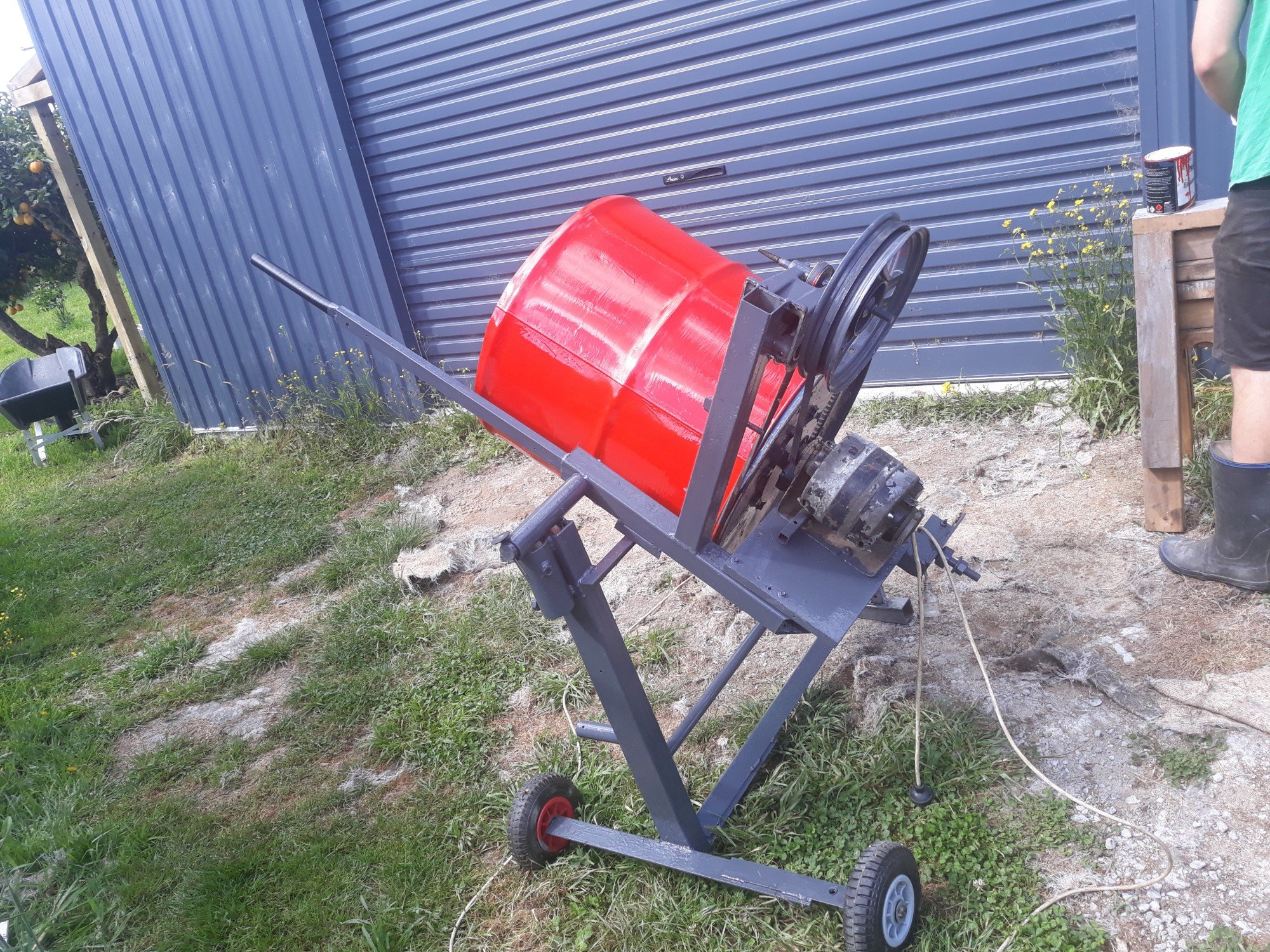
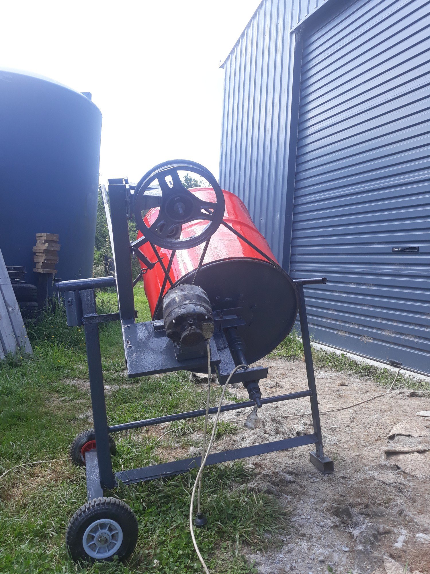
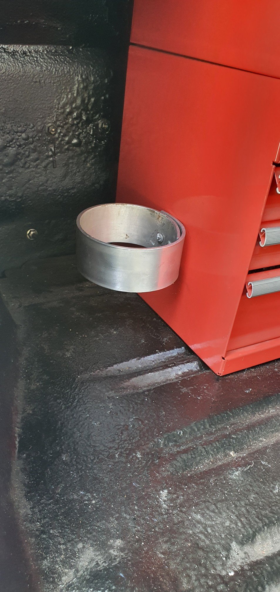
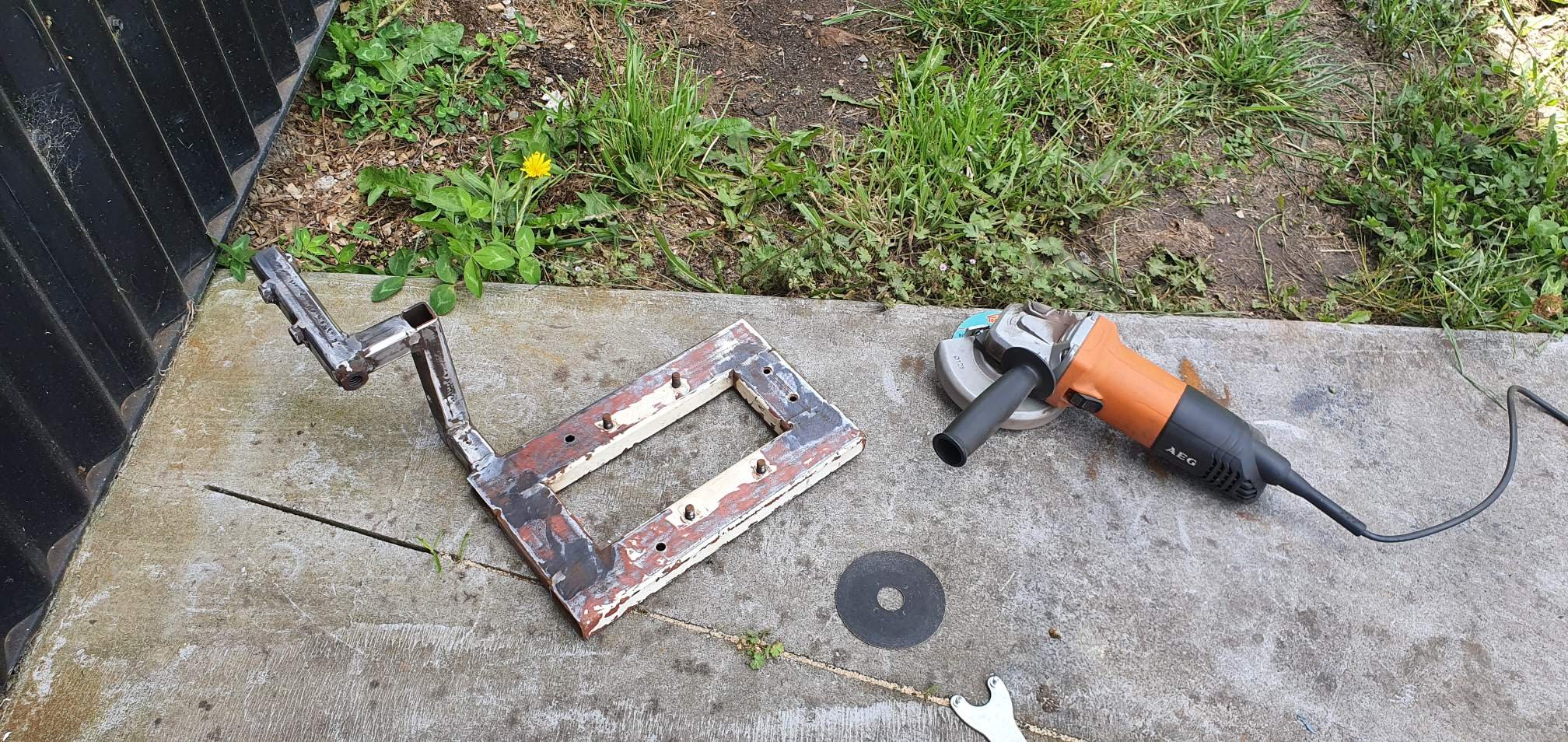
@Guypie has some concreting projects coming up so he made a concrete mixer. Works quite well. He also used the left over 3rd of a drum to make a fire pit that he sold on fb for $60. So the total cost of the concrete mixer came out as -$35. The only expense was the belt, everything else was stuff he already had lying around.
7 points
-
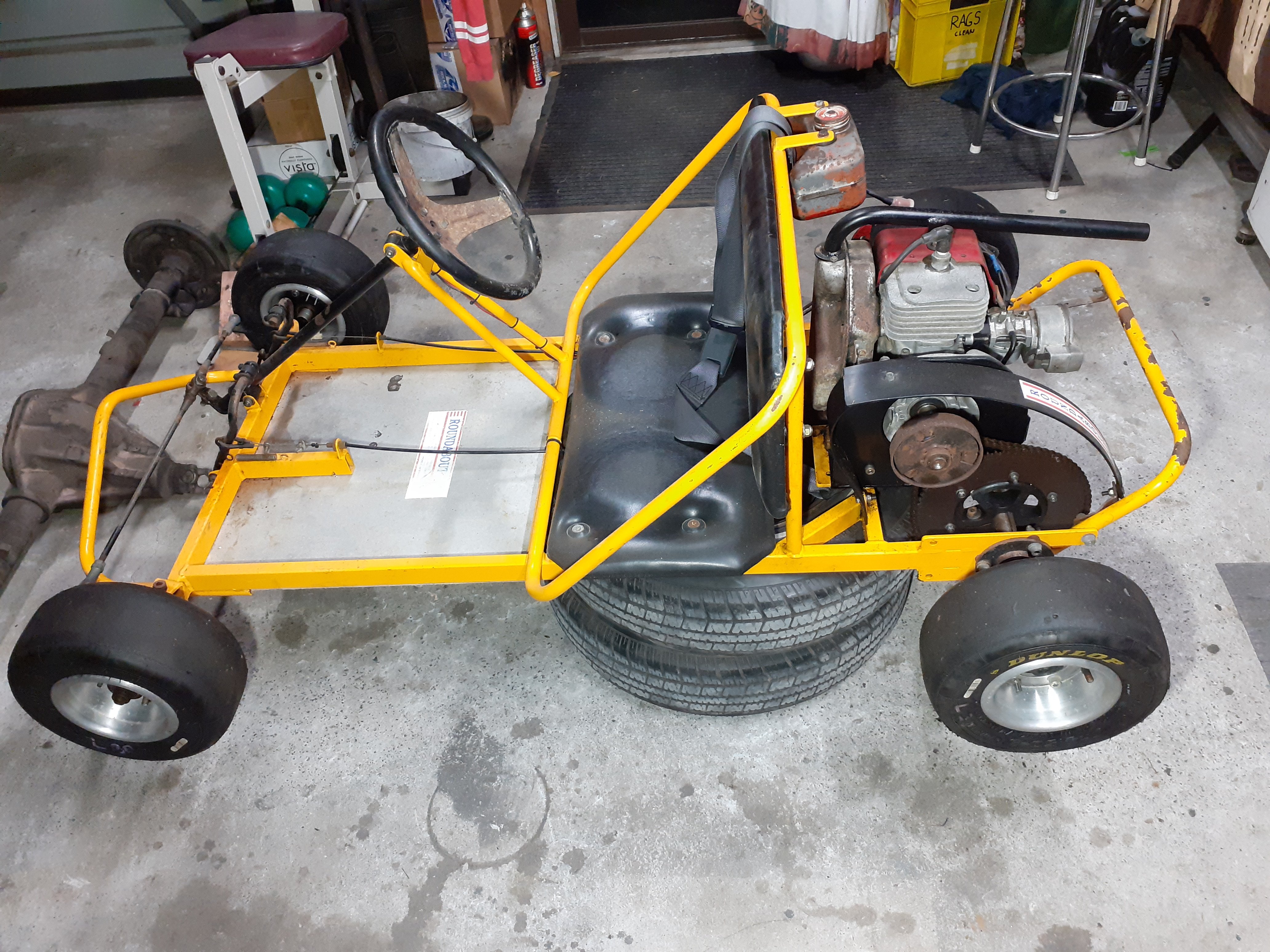
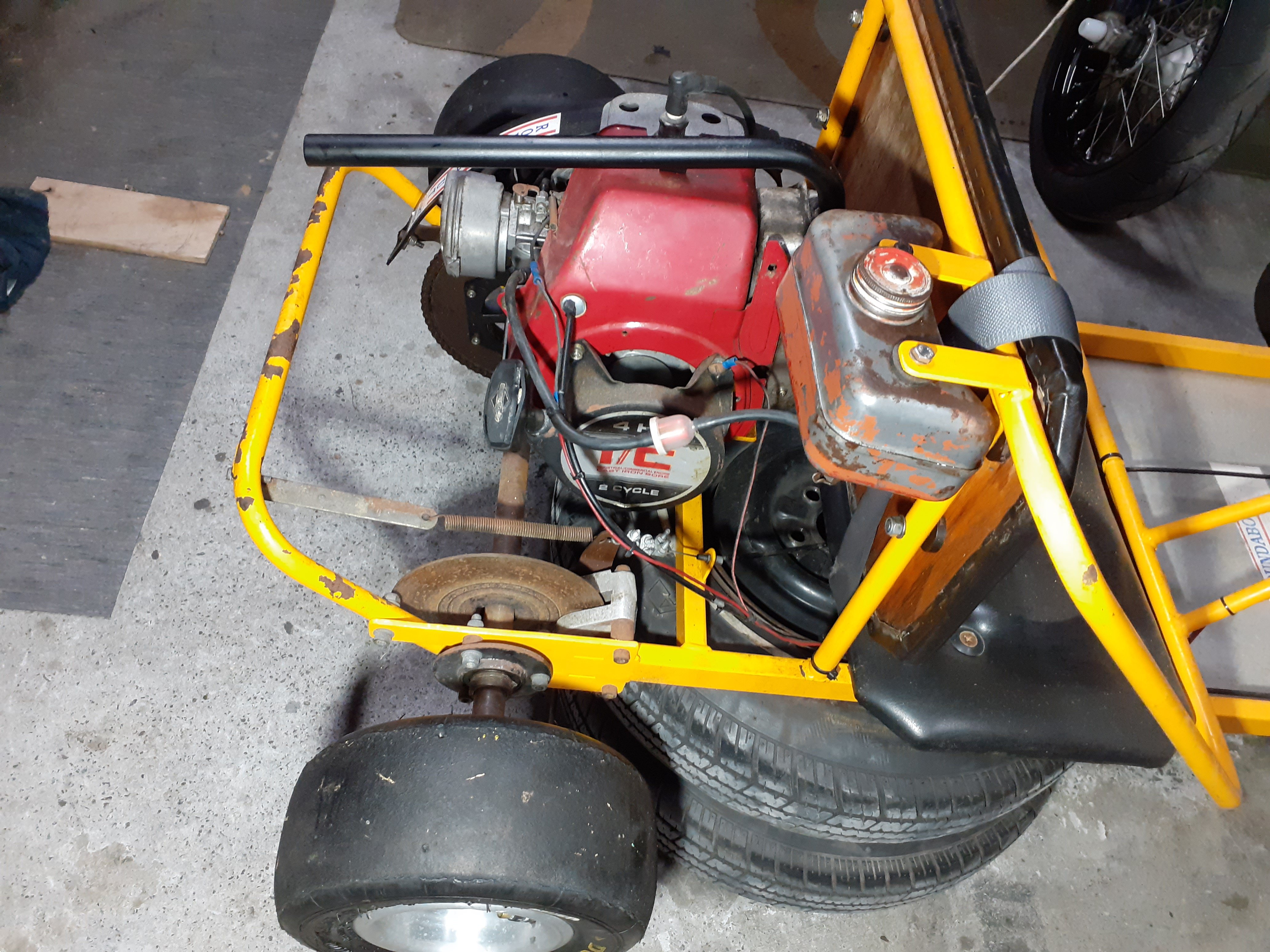
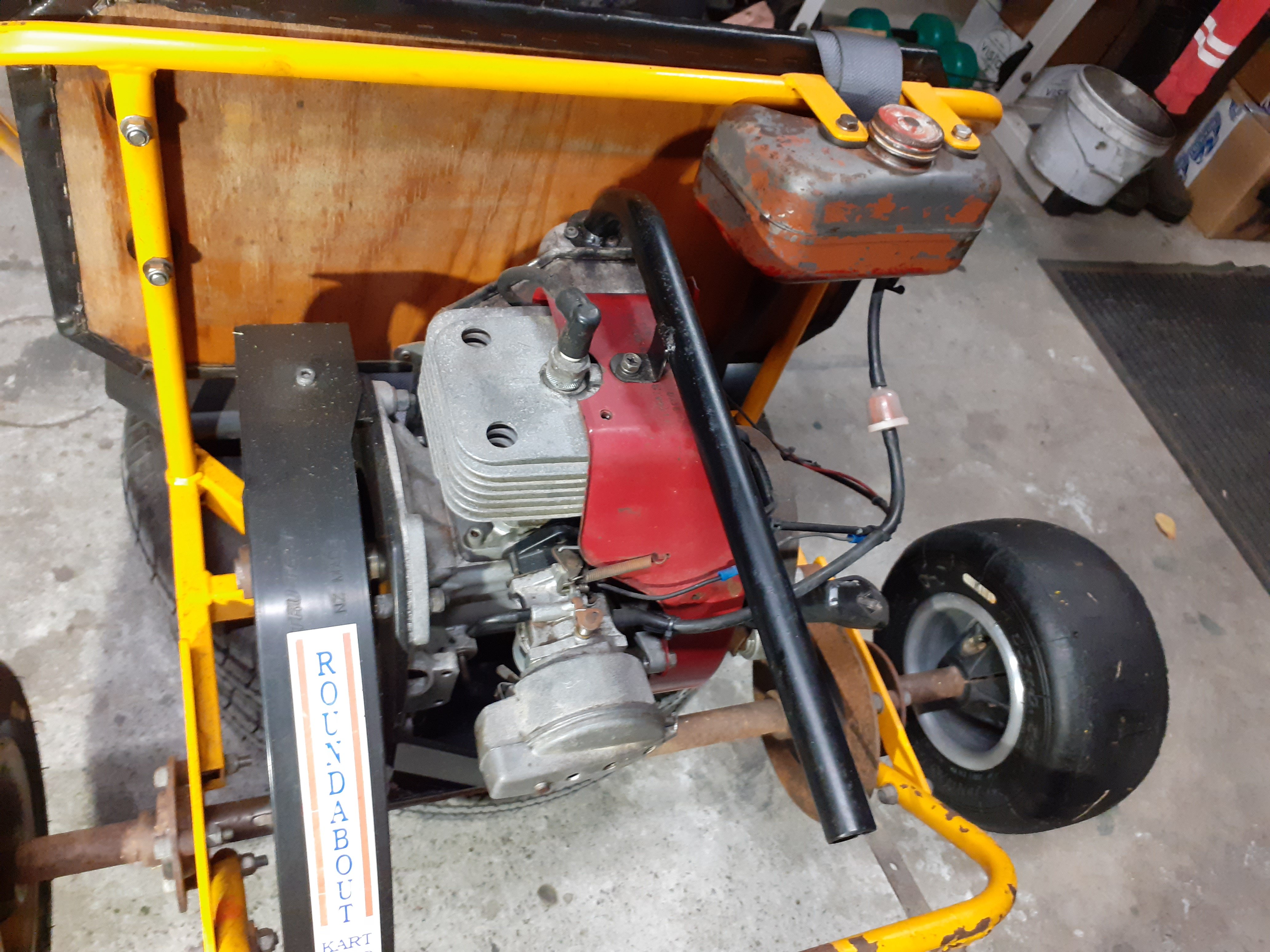
I bought this for my daughter probably 5 years ago. When I was a kid I would have given anything to have a go kart so as any good parent does, I project my childhood dreams onto my own offspring The first time she drove it, I was pretty lax with the explanations, and she was 4. It's a 2 seater so my mrs sat on the other side. I'd backed the throttle right off but on grass with 2 on it, it was frying the clutch and wouldn't get moving so I had to give it more She started doing laps of the grass paddock but freaked out and forgot how to take her foot off the gas so she's going quite quickly, my mrs started freaking as well , kid starts screaming... I took a lunge at the spark plug lead but missed, luckily she hit a bump and her foot came off the gas Left it parked under the house until she was 6. Had another go, gave her a lot more training this time, and took her to an asphalt car park. She was going well until she turned too sharp and rolled it, her and the wife got a few scrapes and bruises. Parked it again, was going to sell it but daughter was still keen to have another go, she's 9 now and asked about it this morning so finally got around to fitting some smaller tyres to gear it down and make it less likely to fall over
6 points
-
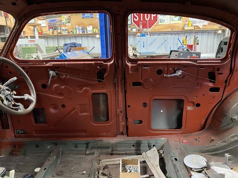
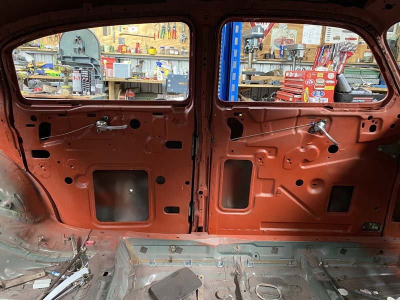
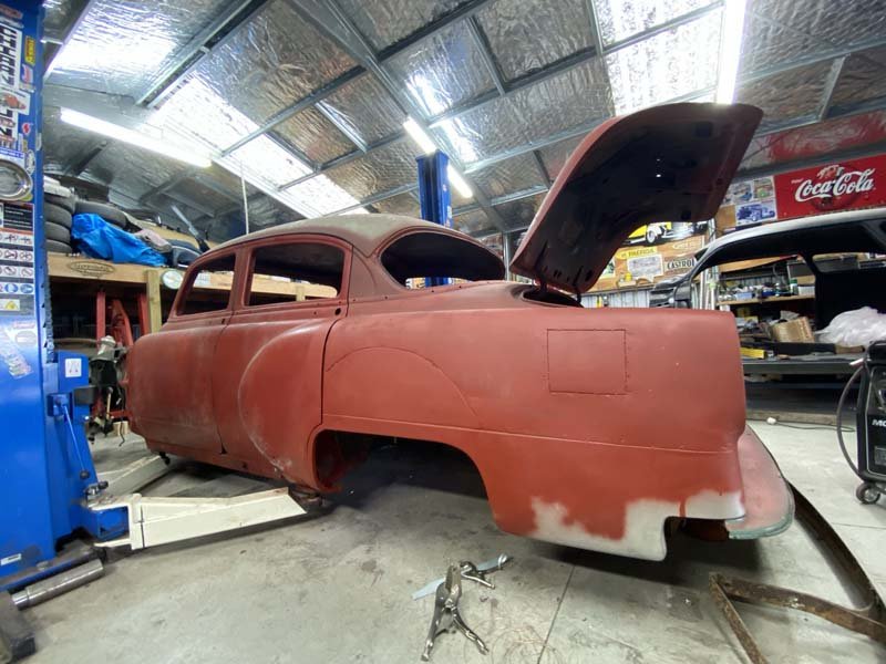
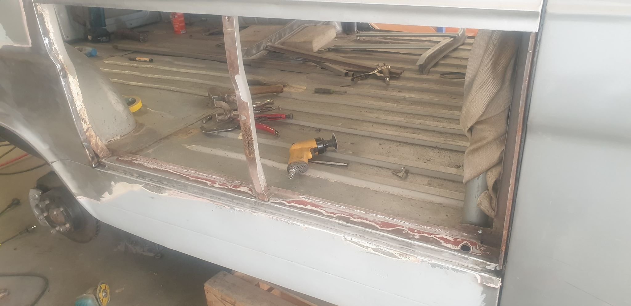
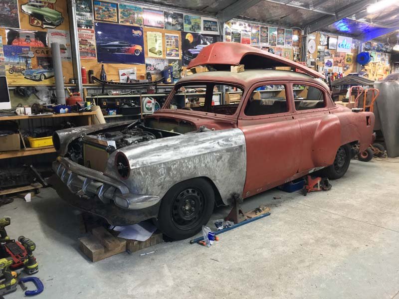
Have all the interior door handles back on. Modified the rods and clips from the Lexus doors. To join the Chevy Handle mechanisms to the Dakota Digital Bear Claw Latches. I had to modify/weld the lever on the Dakota Digital bear claw, so it would pull forward/Back, instead of Up/down. And had to cut the existing holes in the door a little bigger. They work beautiful and reliably so far. Latch smoothly. And have a good amount of movement in the handle, before they release the doors. Next up was the brackets for the rear bumper. Folded up a couple of 50x5mm steel brackets to bolt onto existing m12 holes. Couple more to make for the front of the bumper irons. Then all will be spot welded through the double skin beam in the floor, that the factory tow bar and hooks is mounted to.
6 points
-
Nothing like some time off. To keep working harder. Next up... -Two small holes in the sills, in front of the rear wheels. -Brackets welded to the floor to hold the rear Bumper in place. (as seen in photos^) -Primer, seam seal, then Underseal. -Reassembly?
6 points
-
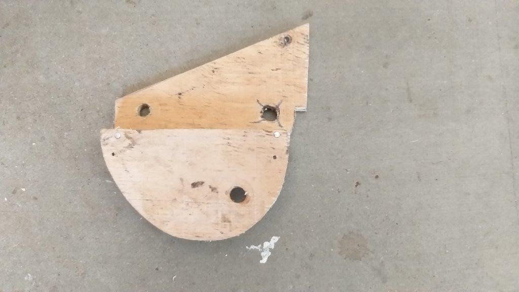
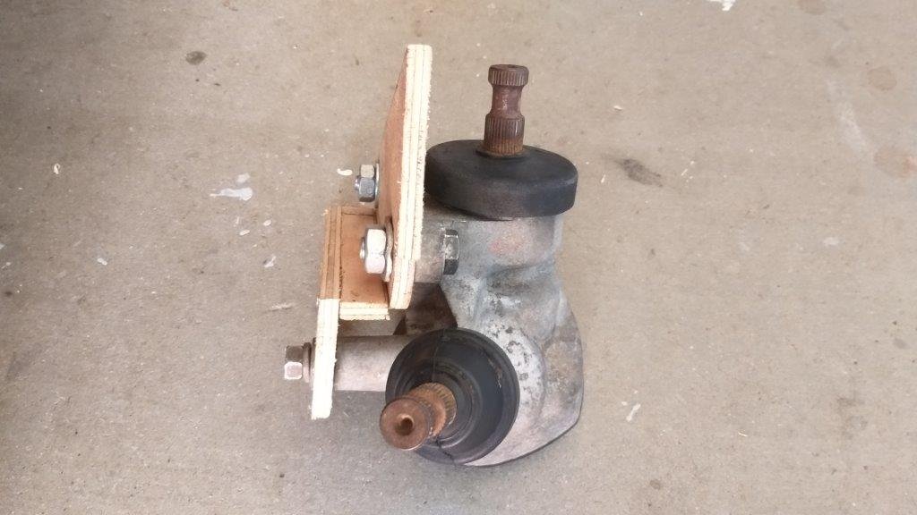
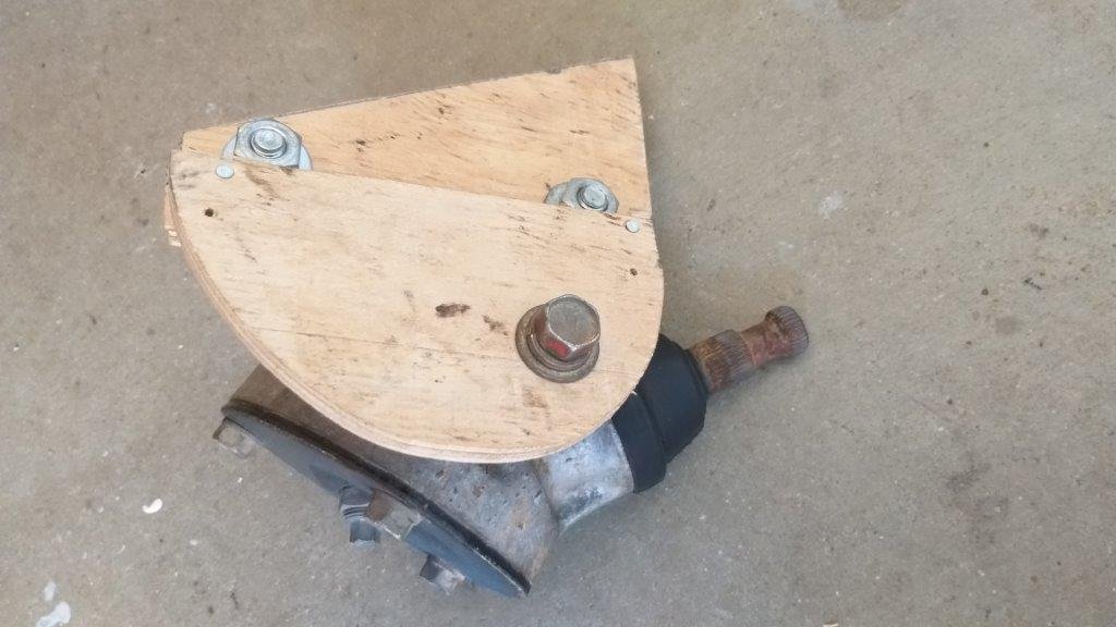
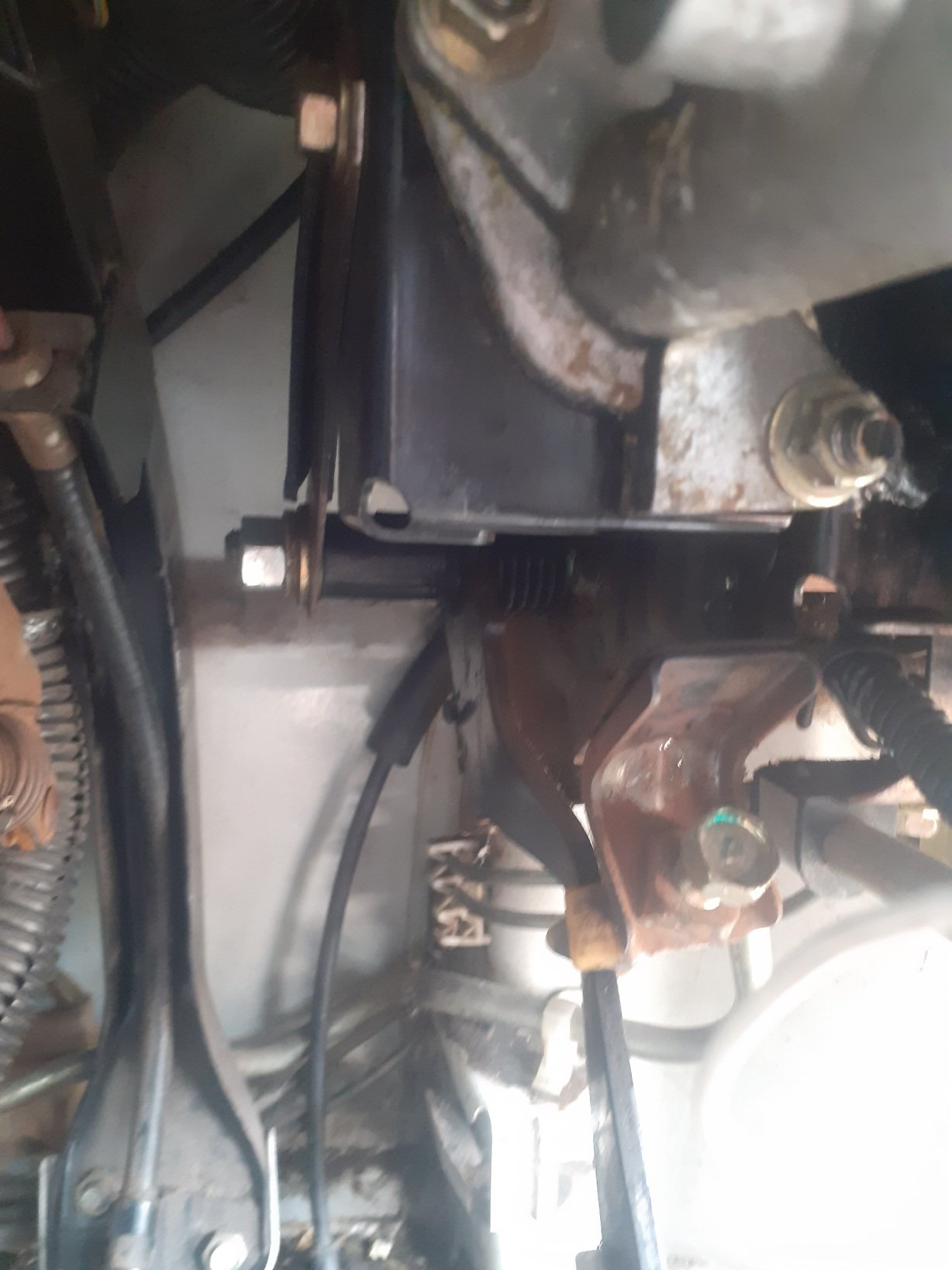
I had mixed success at the rubber place in town yesterday. Managed to get a pinch weld style rubber for my front doors so I was chuffed about that. Sadly they didn't have anything near as large as the 70mm rubber grommet that I need for my steering column. Hopped on fleabay when I got home and the only listing I could find for a 70 mm OD grommet was a crowd in China so I've resorted to ordering a few in. Thanks to Covid estimated delivery date is early March so I'll fabricate the plate in the mean time and will fit the grommet once it arrives. This morning I thought I'd make a start on the second portion of the steering bracket which is the part that the L300 angled steering box mounts up to. Did a bit of plywood aided design and successfully managed a test fit. With the Thames steering column mounted in its final position the L300 UJ that I had welded onto my Thames steering column runs nice and true. Tomorrow I'll replicate the plywood mock up in 6 mm steel plate and will then glue it to the existing part. Thanks for looking.
5 points
-
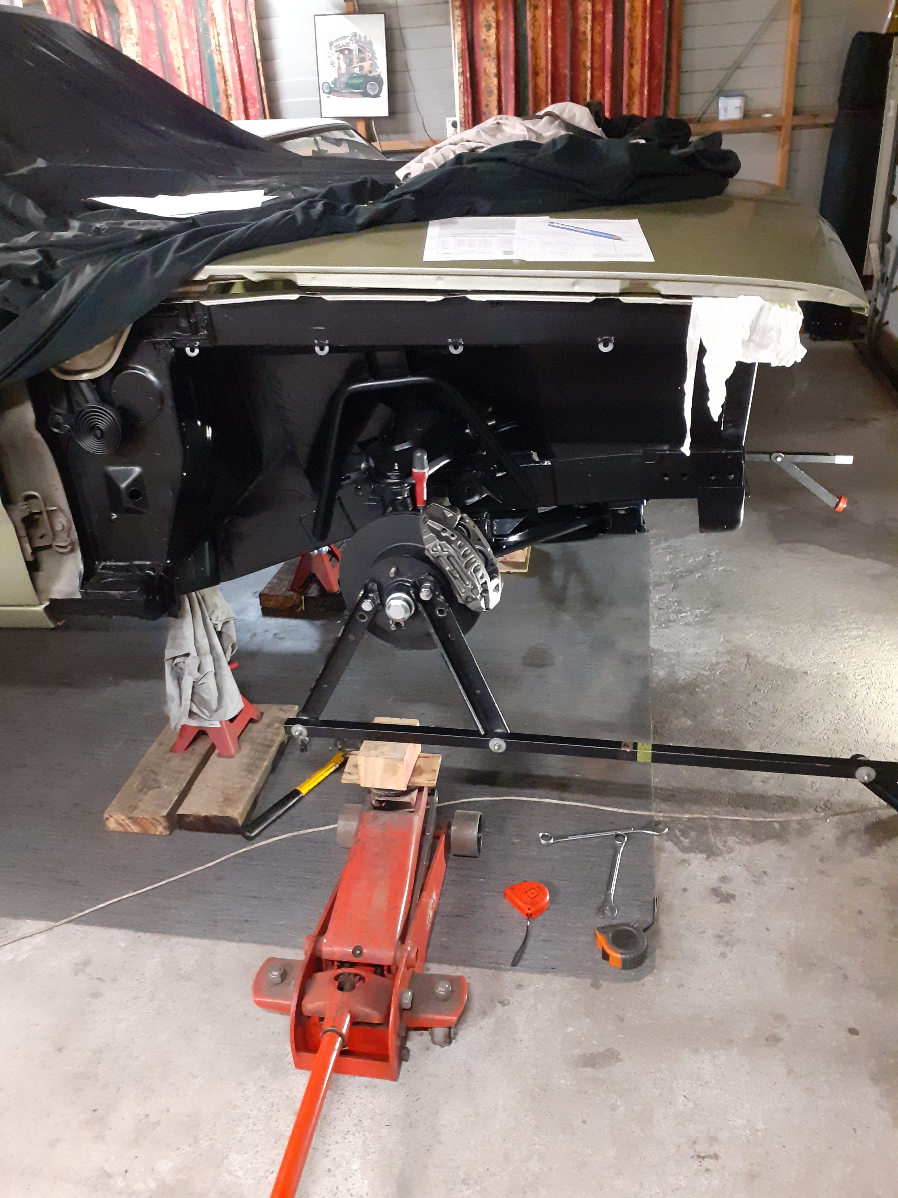
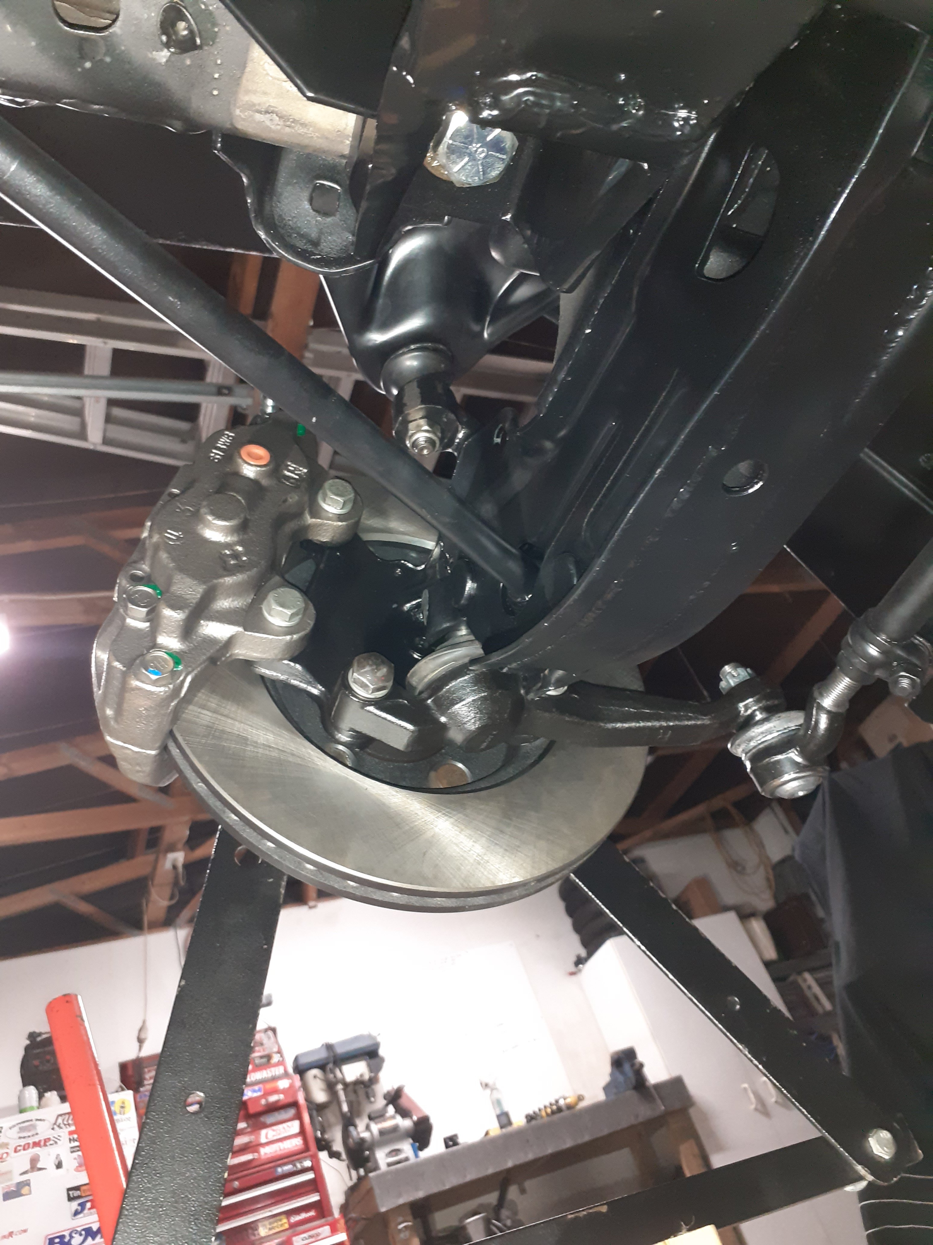
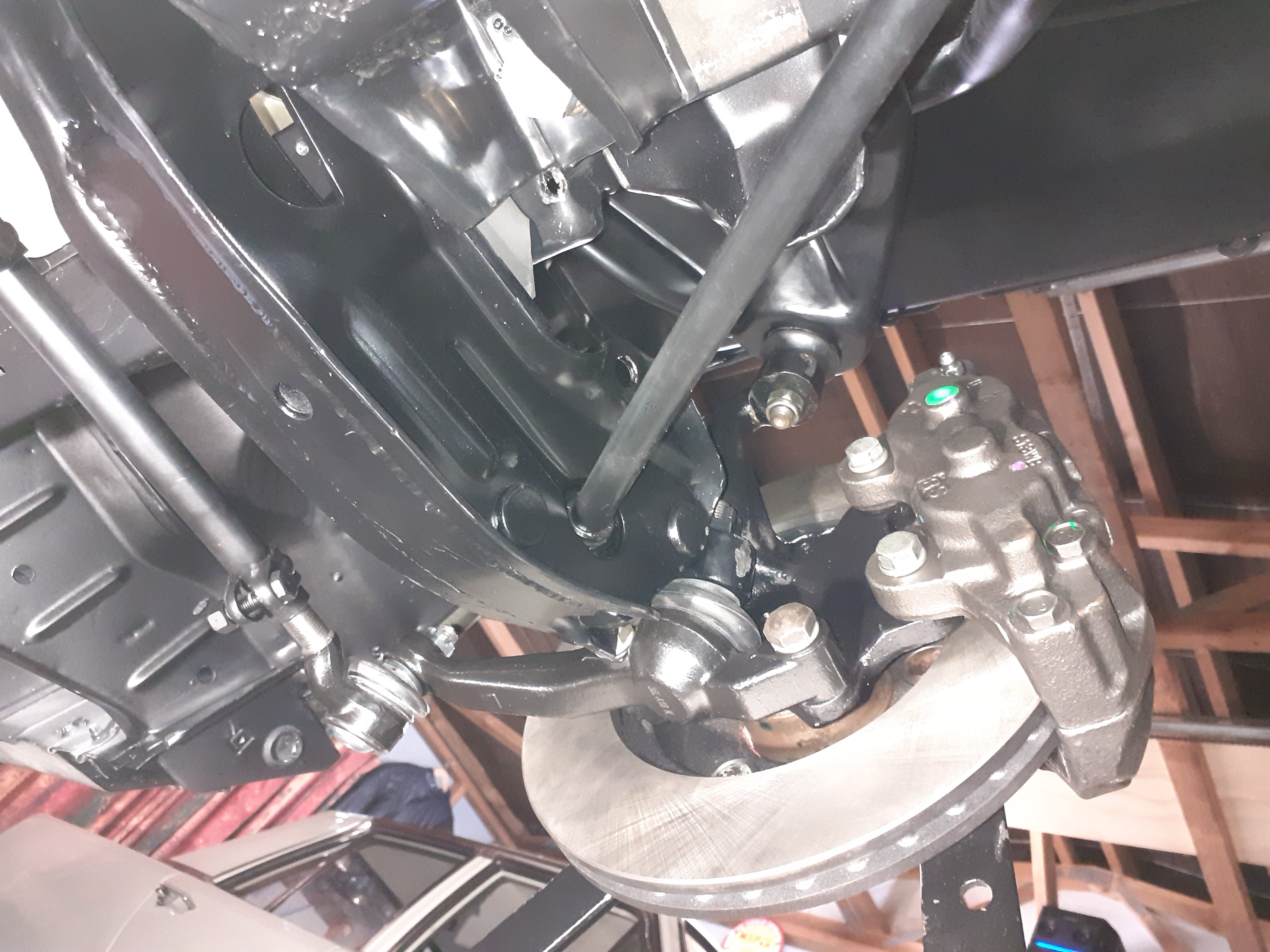
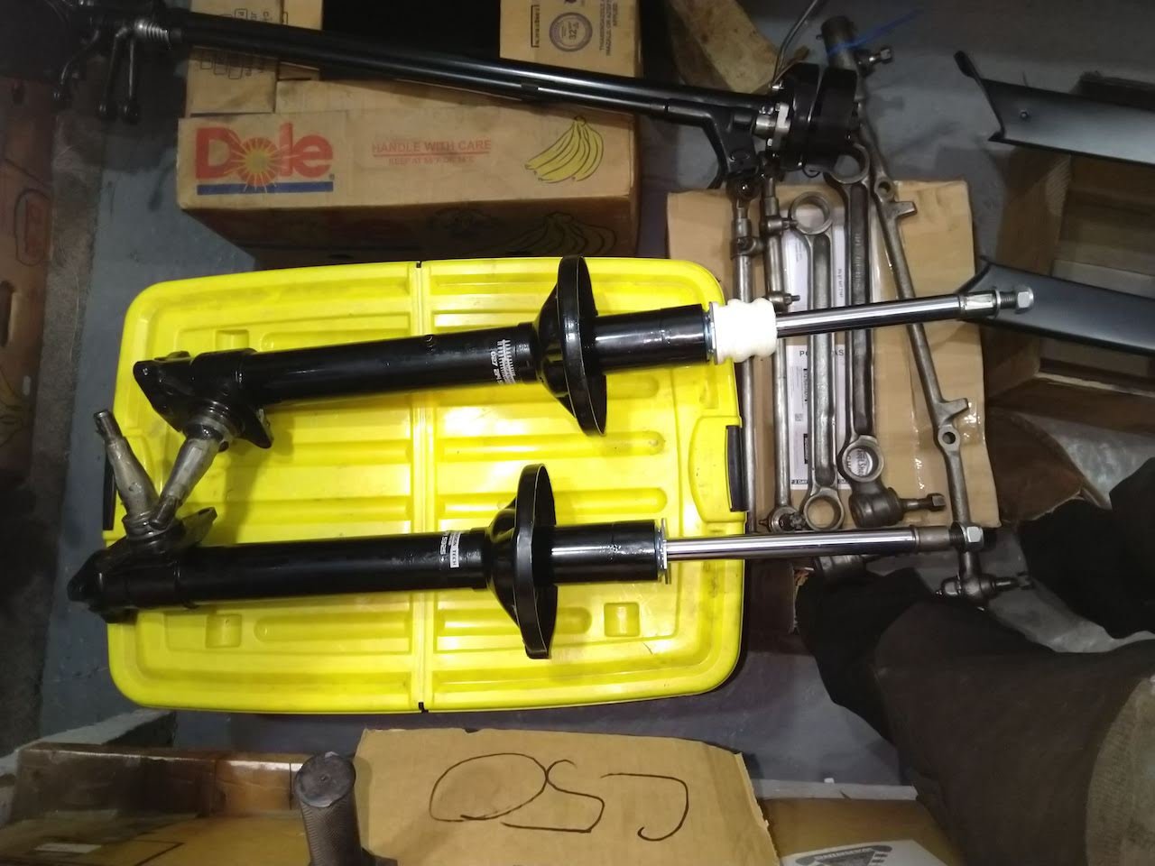
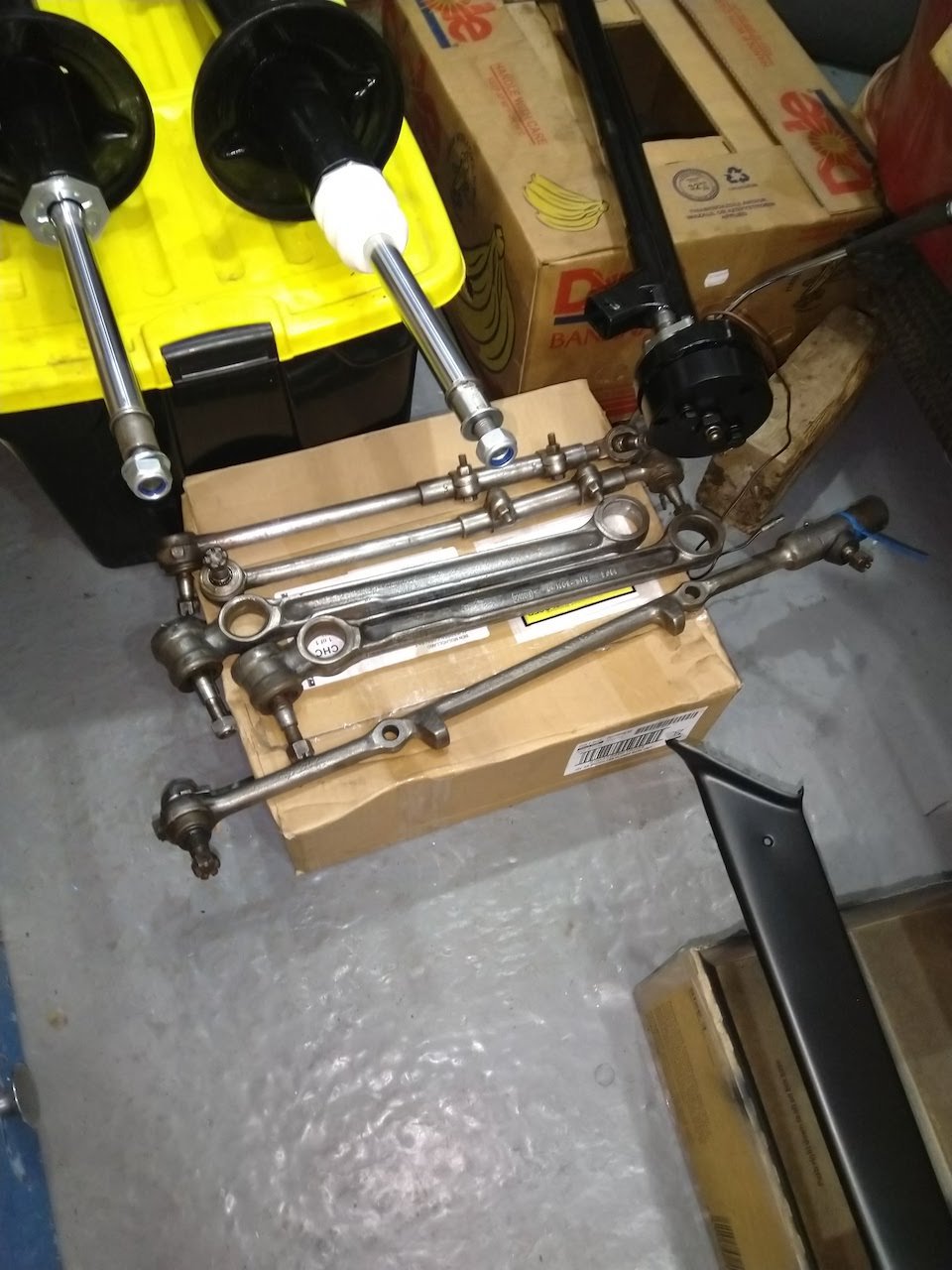
So the new joints arrived this time but they were packaged incorrectly and for a different car. Because the theme for this project is buy things at least twice I ordered some more of the 'correct' ones and am now waiting for those to arrive. I was bumbling around in the garage and looked at it and thought 'I wonder if the spindles and brakes fit the other way around ' as the mount holes for the balljoints are angled. Swapped side to side, did a bump steer check , that got it down to 13mm, it had what appeared to be a shit ton of caster and the top ball joint was getting close to binding, so adjusted the top arm a bit and rechecked it, down to 5mm now with camber and caster in the ballpark Other people are having xmas parties, I'm in my garage quite excited at improving my steering and suspension geometry, what a nerd
5 points
-
I'm pretty sure they were NZ made in the 90s. I used to race a kart when I was 13-15. Roundabout kart shop was where we got my kart and parts from and I vaguely remember seeing a brochure for these It has a 4hp 2 stroke briggs on it that has been turned from vertical to horizontal shaft , it has a carb and fuel tank from an iron horse mower by the looks of it I made the exhaust longer cause it used to just chooch straight up out of the muffler
4 points
-
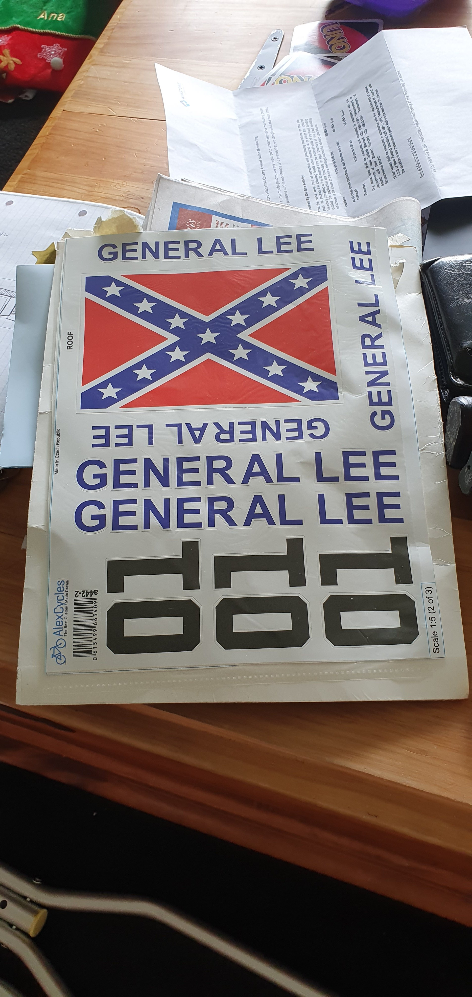
Crazy expensive, but worth every dollar. 3 A4 pages of custom decals made to order. Dah dah da dada da dada da dahhhh...
4 points
-
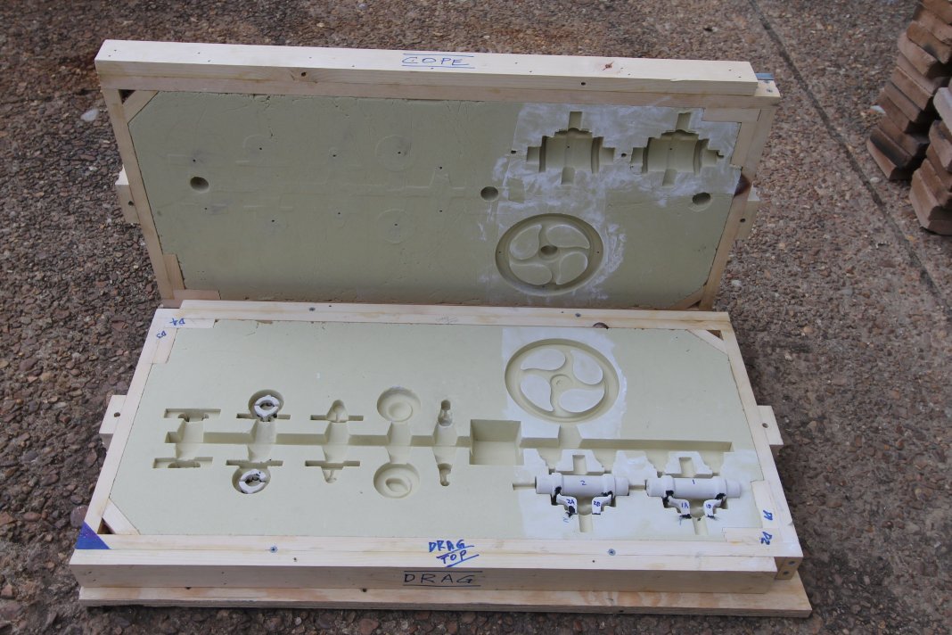
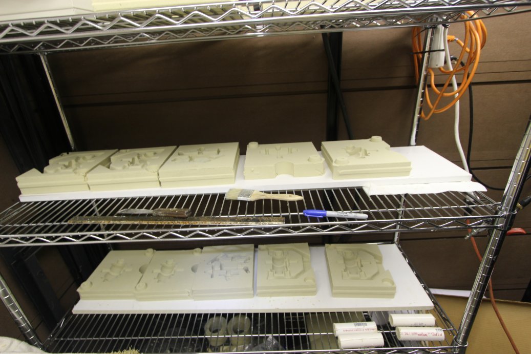
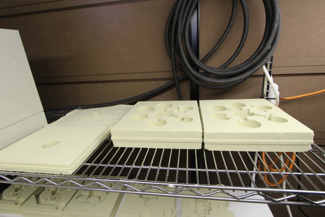
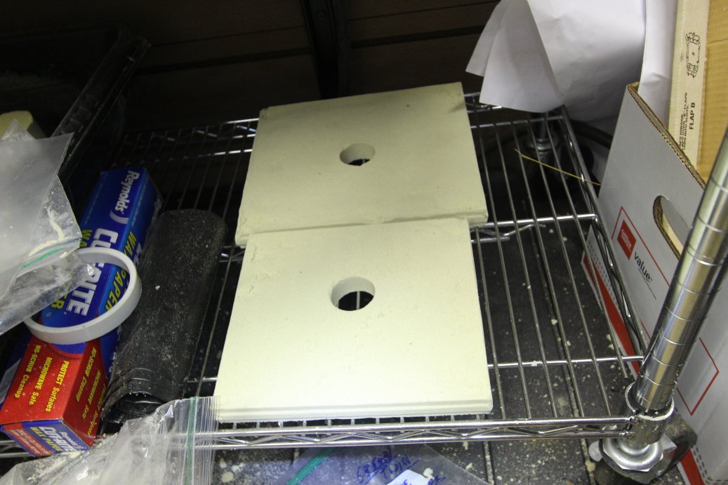
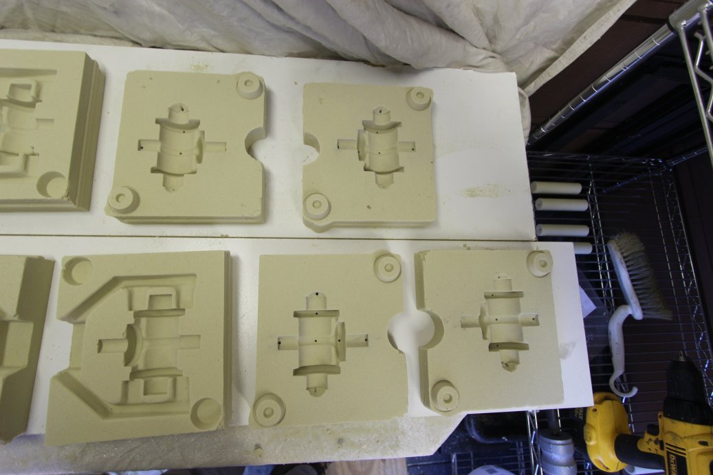
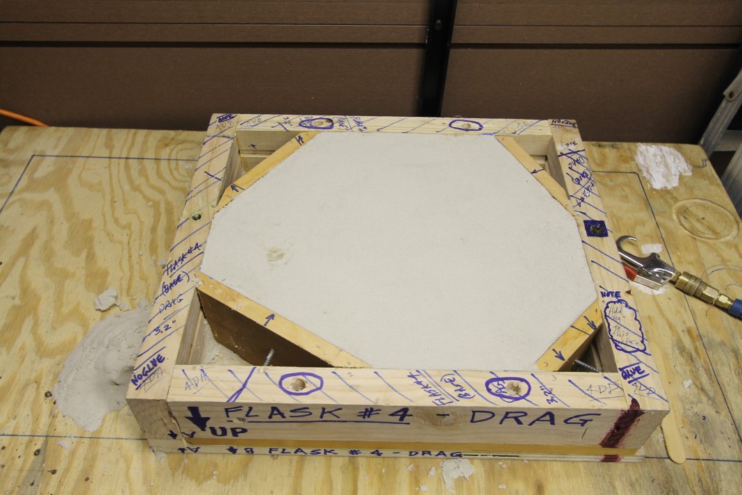
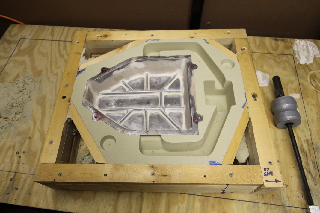
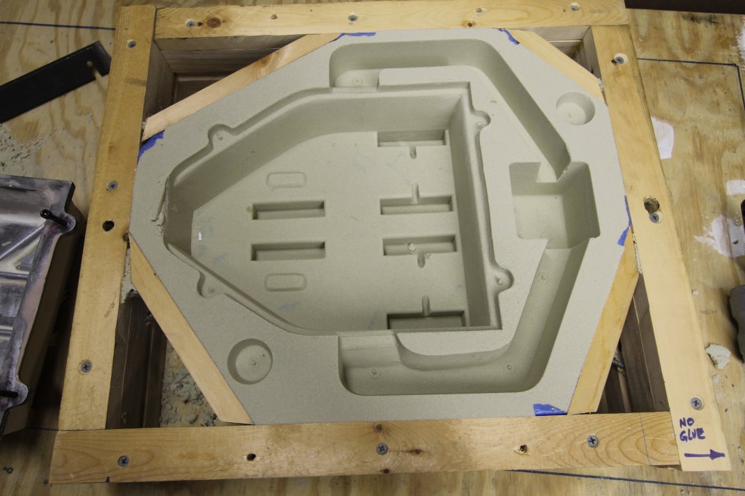
I glanced at your molds, and I would say you could probably reduce their weight by 1/2, but I don't think it would be worth the trouble. By the time you fooled around with filler blocks, and then perhaps had an irregular shaped mold, and risking one or more parts of the mold being too thin and blowing out, I think it would be wise to stay with the mold sizes you have. For me, if I blow out a mold, I can just recast the piece, and my molds are not nearly as complex as yours. I think you need extra mold strength to keep things intact during transport, and while being manhandled at the foundry. I have never had a mold fail, even with spots that are 1/2" thick, but my pours are generally 20-30 lbs of iron. I did have a mold separate once due to hydraulic pressure when I did not use enough weight on top. Below are a few molds I have made. The runner was too small on the long mold, and not all the parts filled. I typically use smaller flasks now with fewer parts in each mold. .
4 points
-
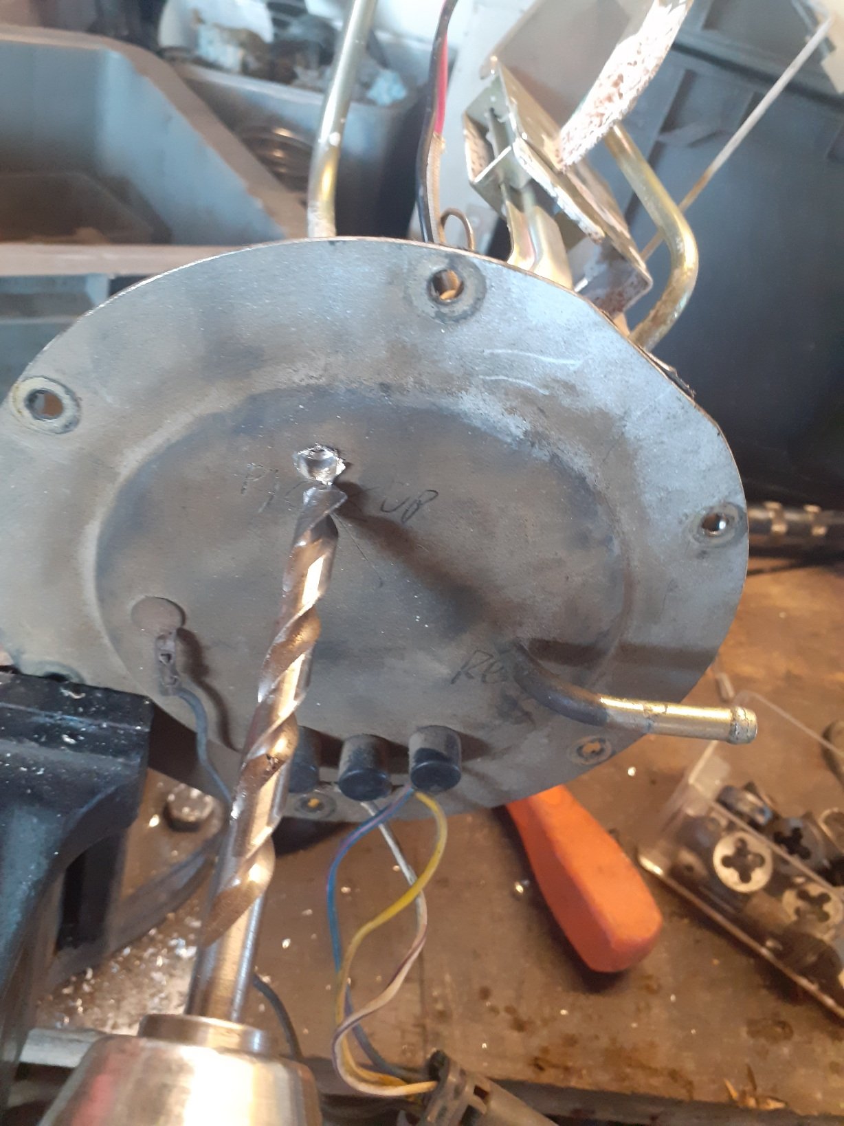
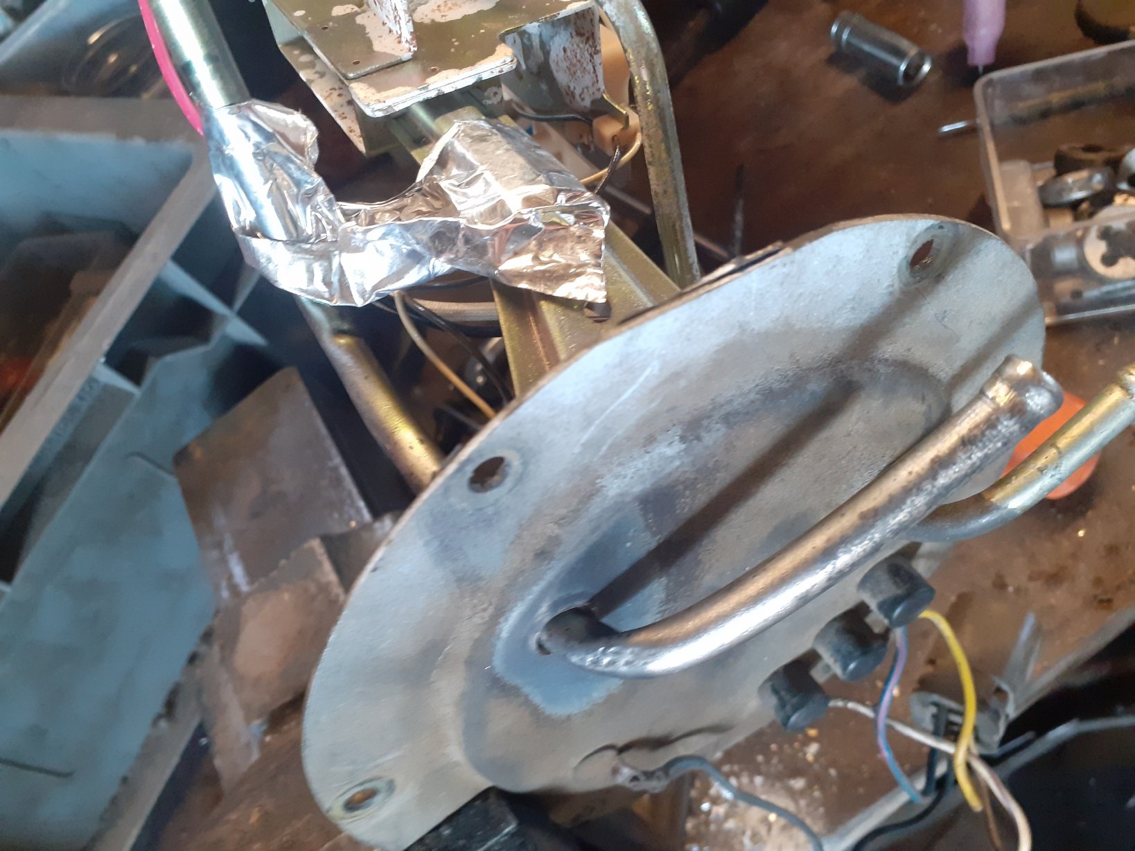
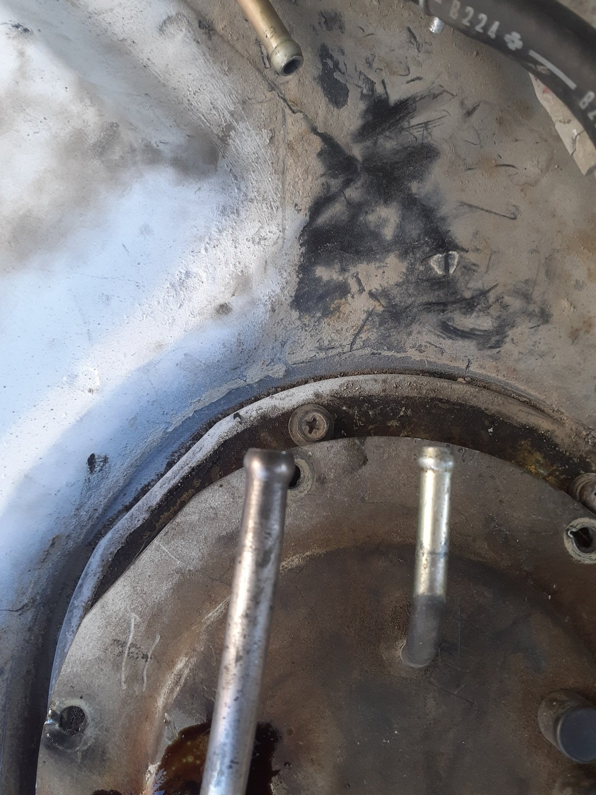
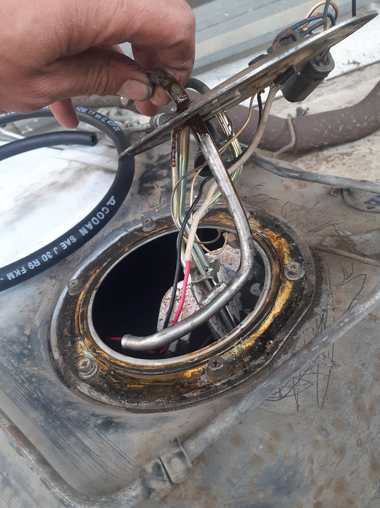
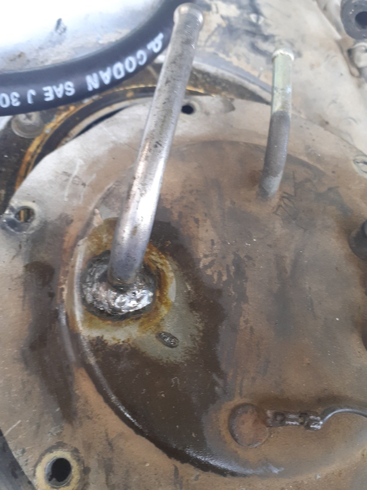
While I was mucking around with the fuel system, I noticed that the sr20 fuel rail inlet line was bigger than the line coming from the tank, sure enough I had to upgrade it to 5/16 as silvia lines are, no idea why it worked fine before but I decided to at least upgrade the pump line, the return should be fine with less volume... I found an old rb25det fuel rail in my pile of hoardings from years ago, and cut the line off that. Flared the end and welded it in the appropriate location, and brought some r9 fuel injection hose from supercheap, to replace the puny hard line. The in-tank line will be r10 rated submersible hose. Dont mind my rough bending I had to make another one later on and it came out better as per last pic lol
3 points
-
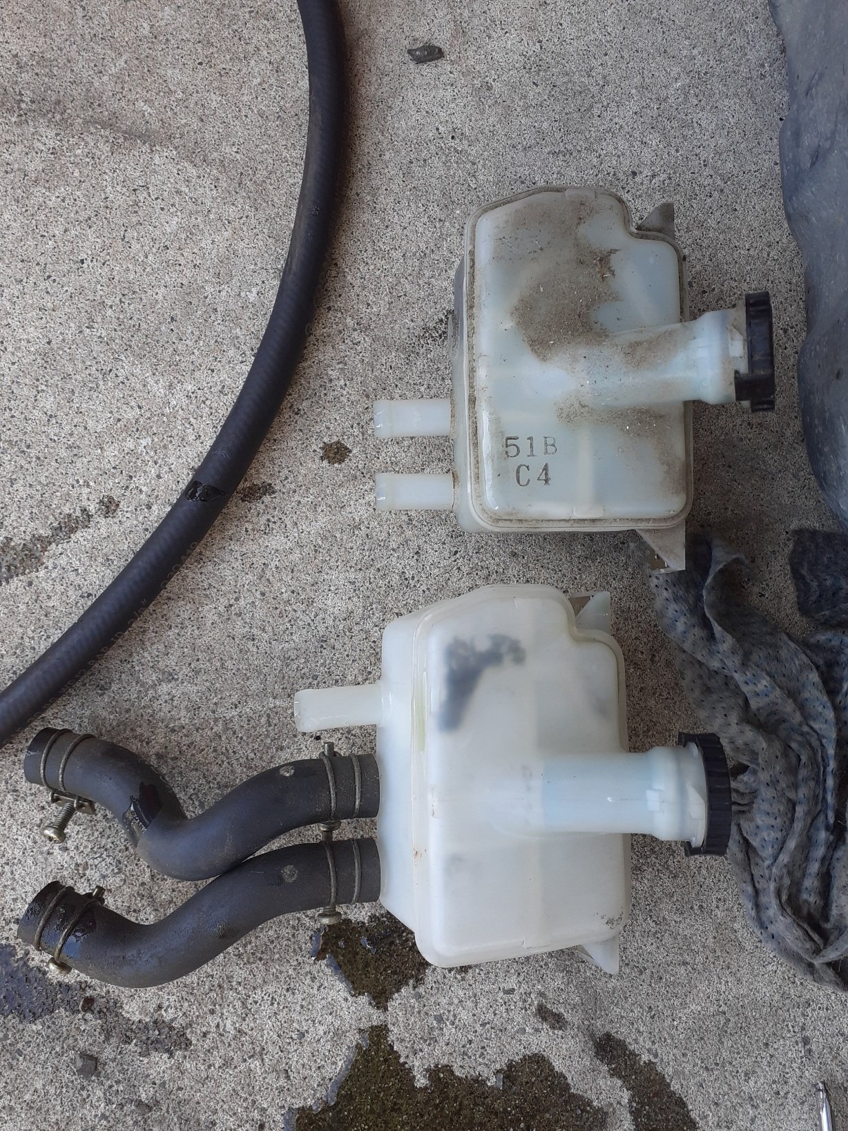
Having done the pedal assembly, I now swapped over the 3 hole resiviour... having a donor car sure pays off
3 points
-
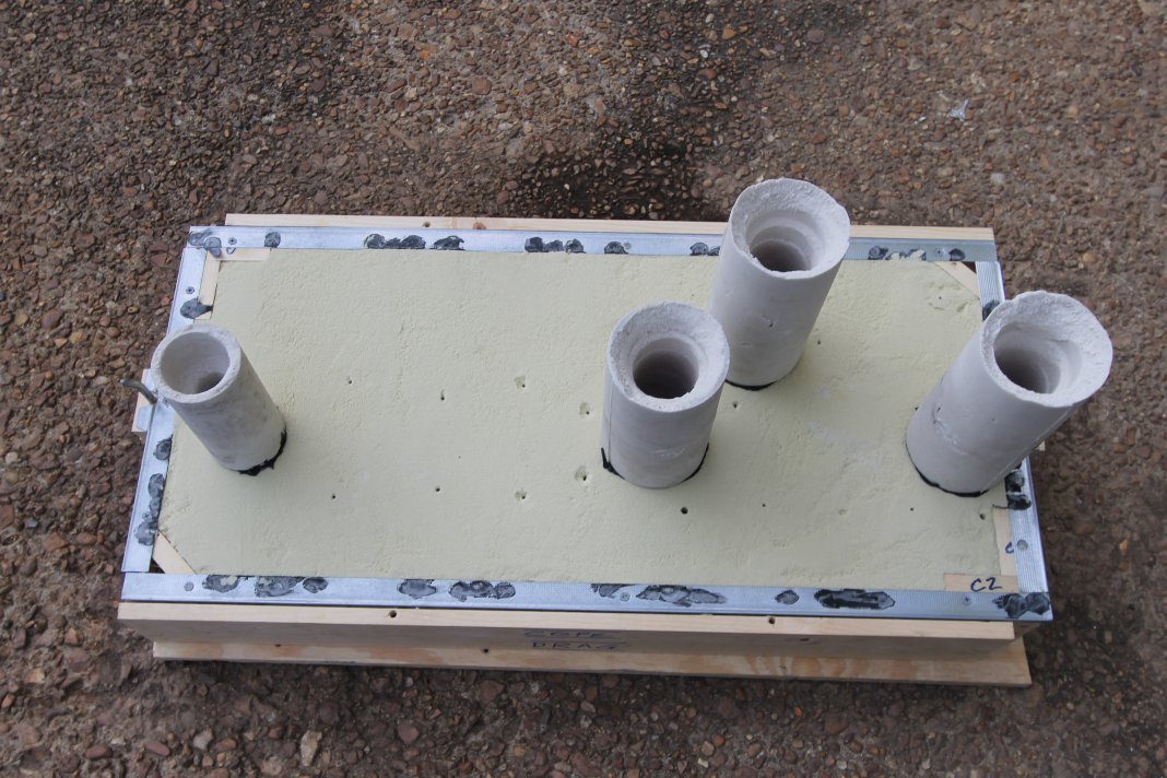
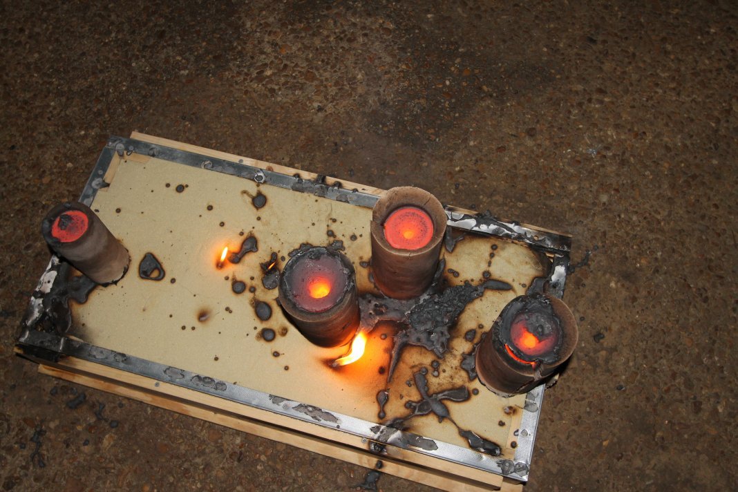
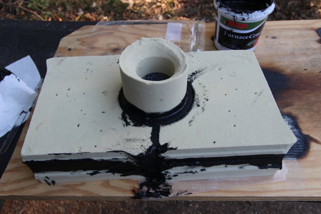
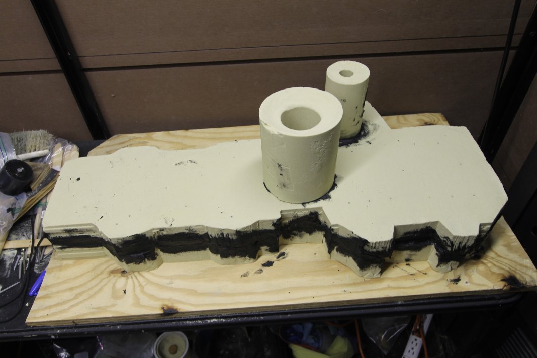
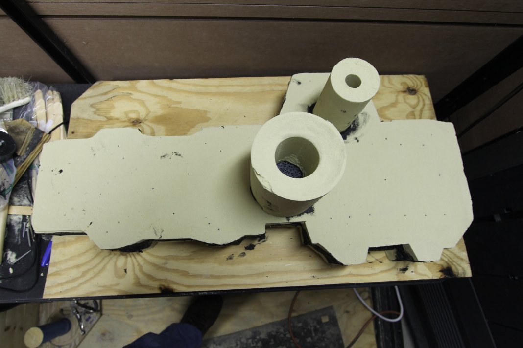
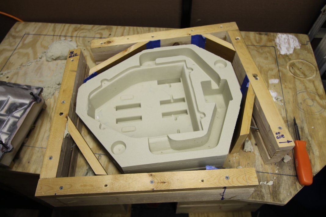
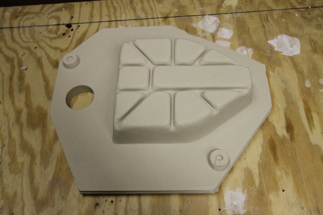
Exactly. This is what I keep a check on all the time. Im not doing sand casting because I want it to be a hobby. Im doing it because I need the parts.. So I dont like getting bogged down in stuff that isnt moving things forward. I do want to get good at it because I have a lot parts to do, so I do spend more time testing different approaches to pattern prep and runner systems by doing several castings. I can do 30-40kg of sand at a time so if I partition off the pattern I can work my way through it at home. Once Ive figured out how well the assembly goes together then Ill go to the foundry and fill the sand in one piece. This was todays job.
3 points
-
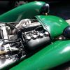
Old vs new. Think looks a 100times better. Gona buy some metal polish and give the crome some love
3 points
-
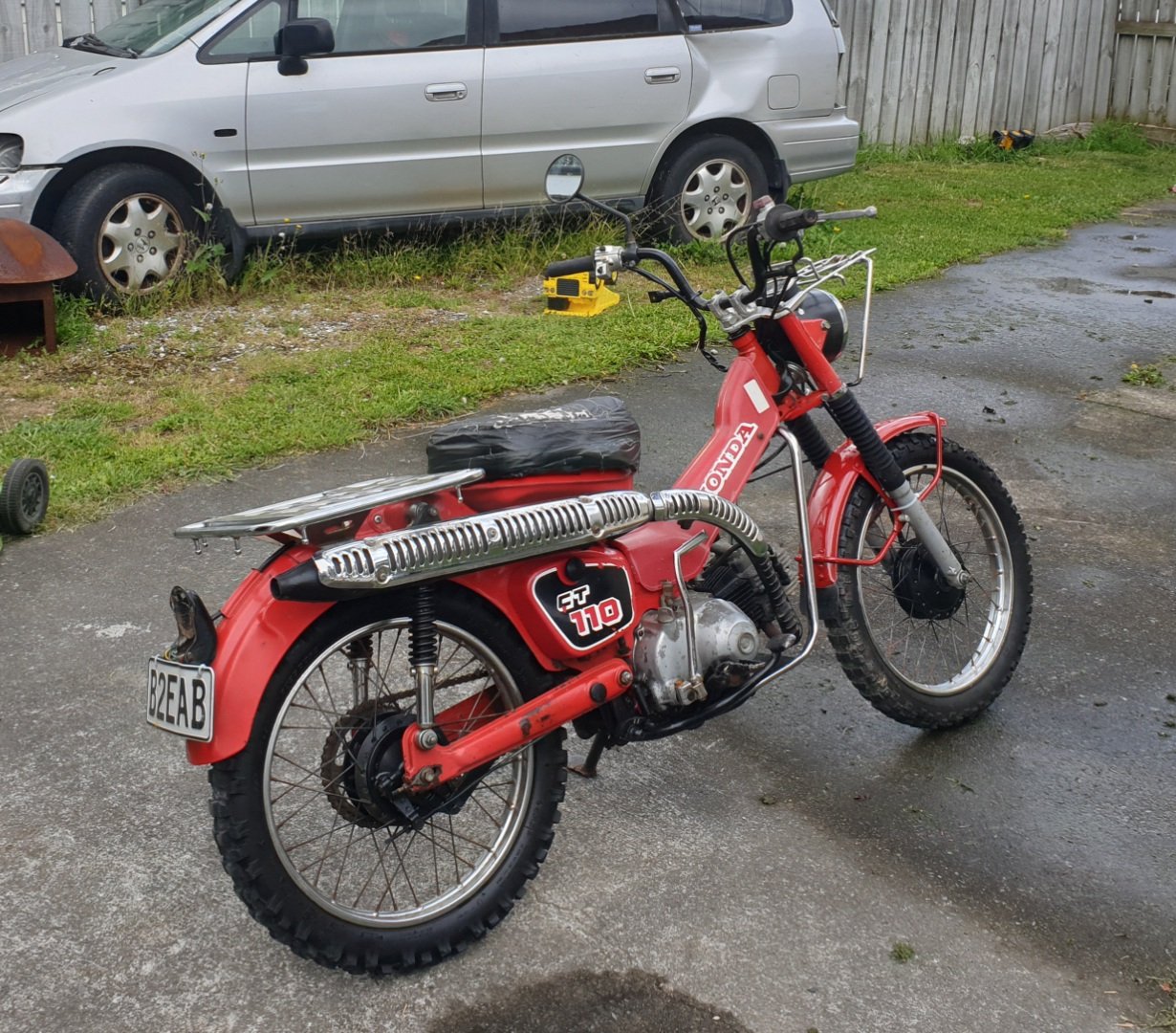
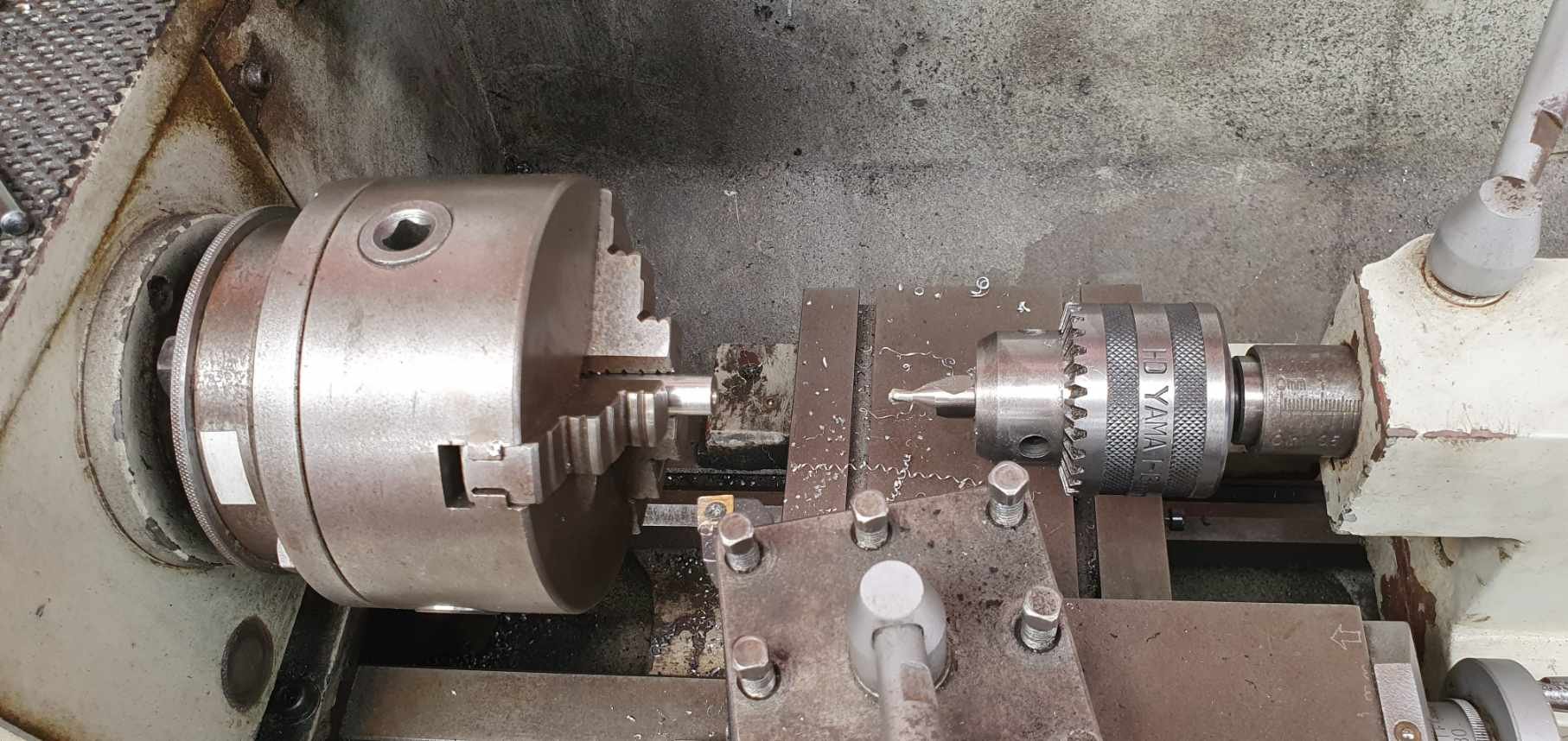
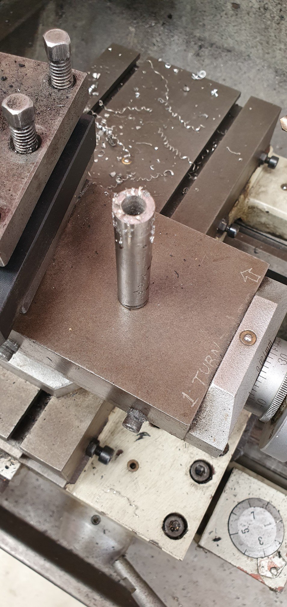
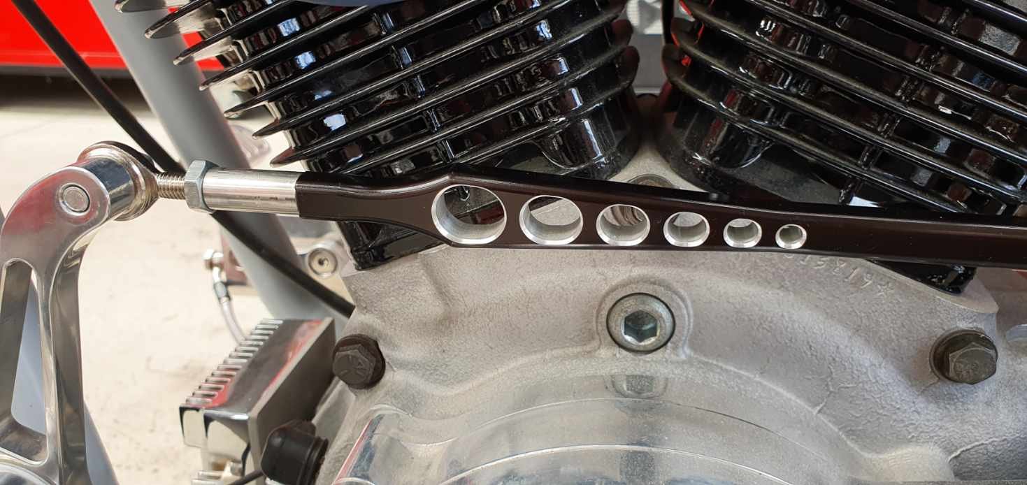
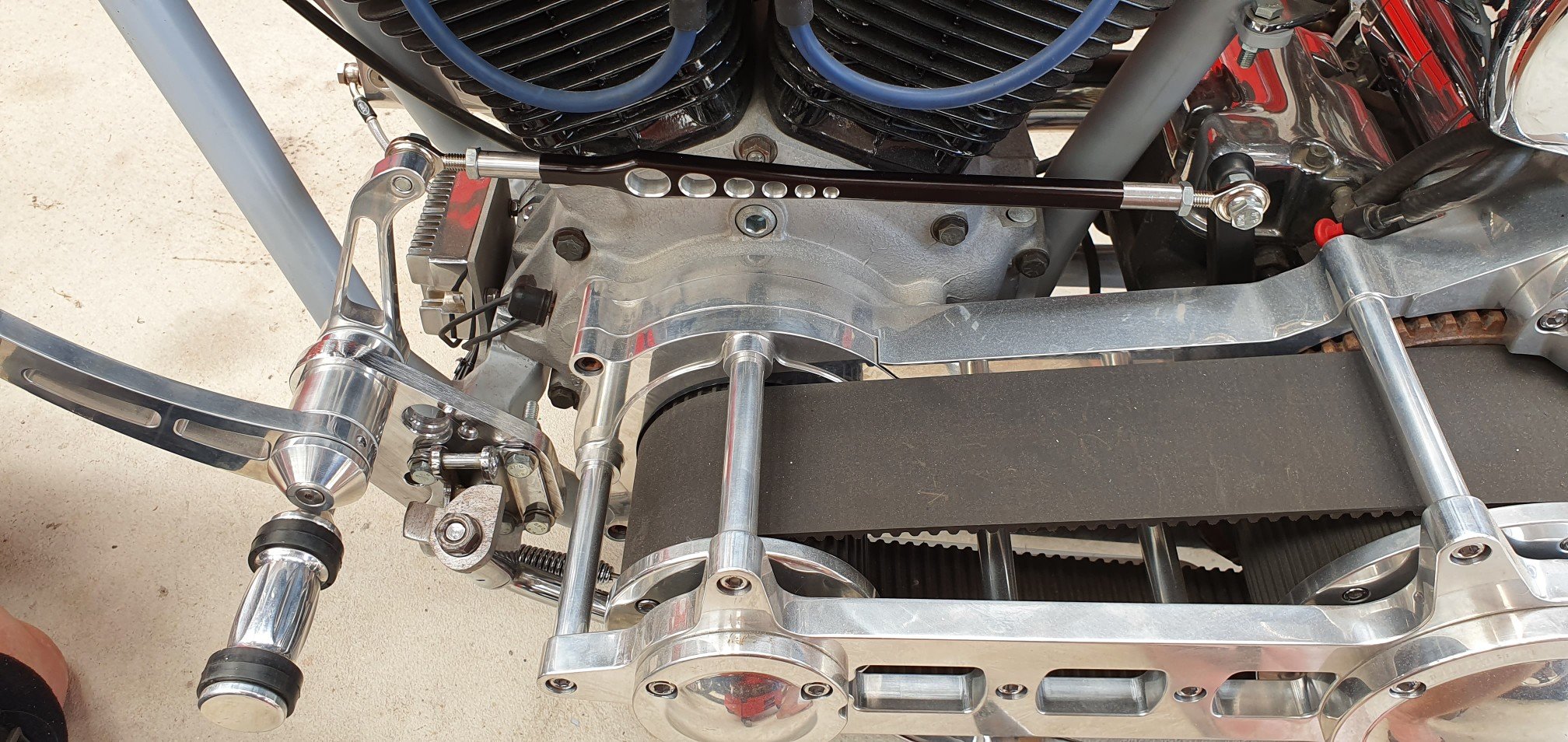
The shift linkage ended up on a less than perfect angle after shifting the centre point about 100mm. It worked, just...but was shit. So I machined up some stainless rod to extend the length, as hey let's be honest, a little more length is high on most guys wish list: I then tapped an M8 thread through it, and used about 30mm of M8 threaded rod to connect it to the existing linkage. This added ~60mm in length and i made the rest up by having the threads out a bit on the rod ends. Boom!! Now the linkage has near 1:1 give or take mechanical advantage, so about as positive as you could get in a set up like this. how does it work now? Perfectly...Fuck yeah!!
3 points
-
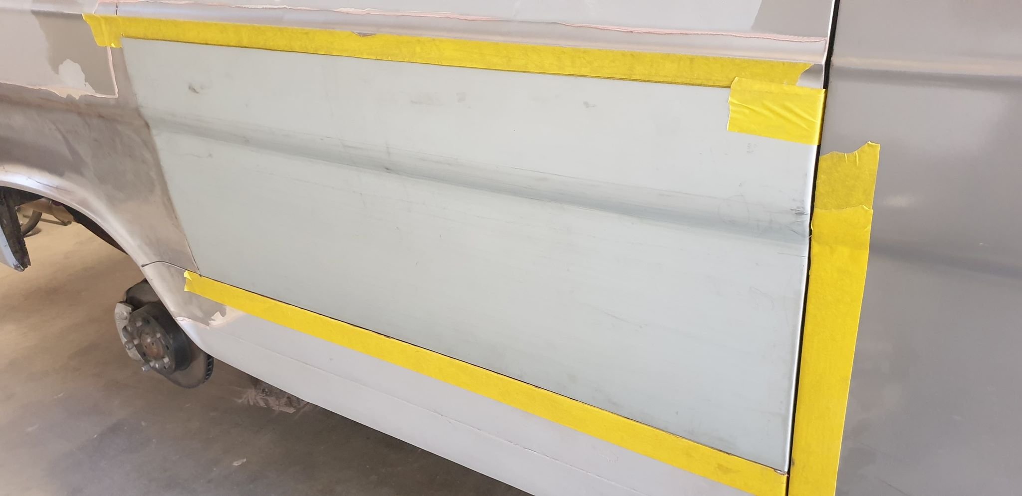
i love me a good christmas car painting. i was looking at some of my other build threads and christmas is definitely the time i paint cars. dunno why? anywho, ive nearly finished the passengers side but i needed to get some paint on the drivers side so its got a couple of days to harden before i start sanding it. so today i applied some primer. also i figured out the blocking problem i've been having with my primer gun. turns out the pot vent was blocked. what a dick. 2020-12-24_05-22-20 by sheepers, on Flickr 2020-12-24_05-22-30 by sheepers, on Flickr3 points
-
not surprised actually
2 points
-
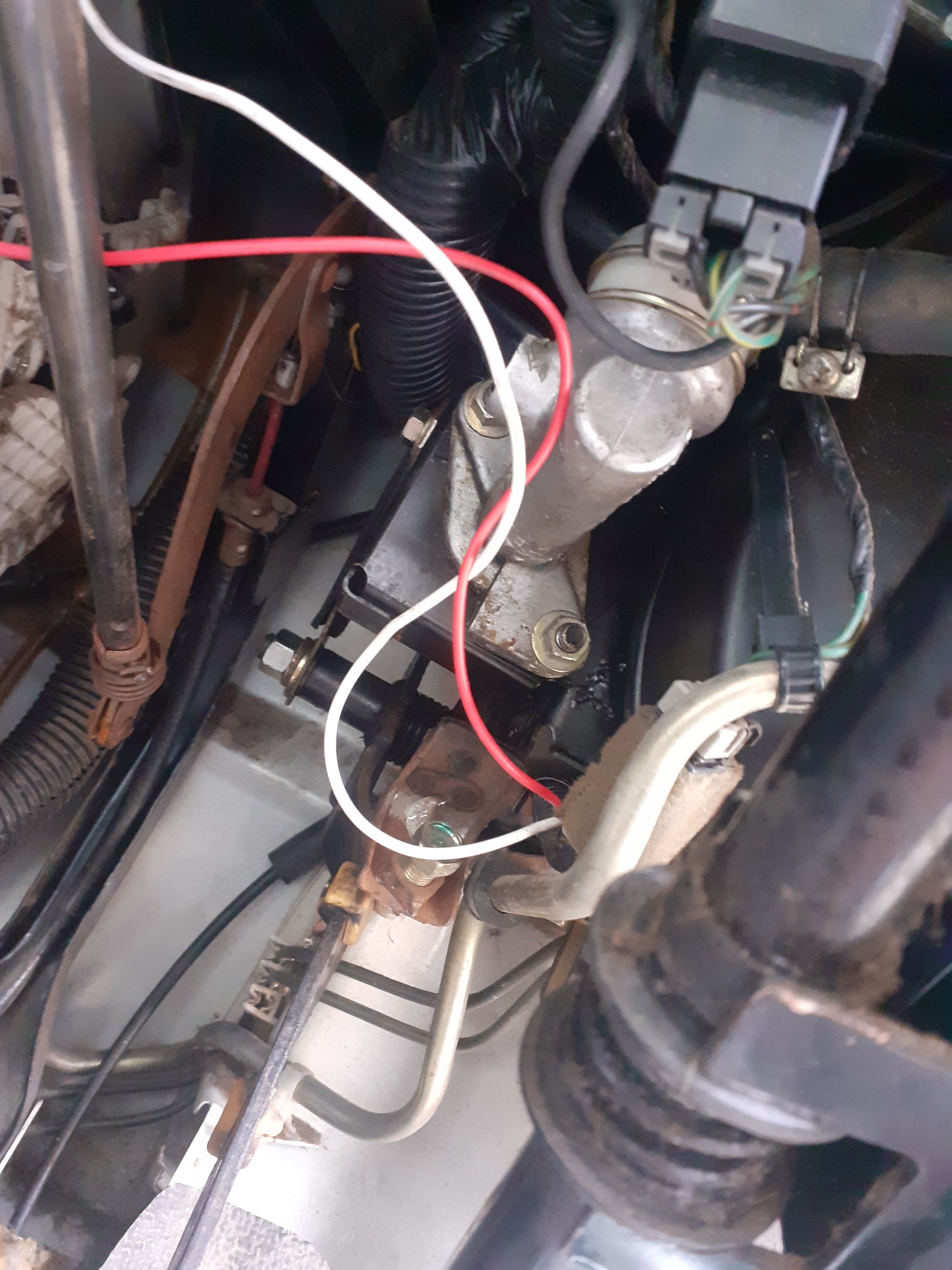
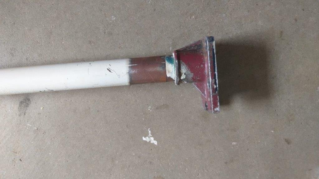
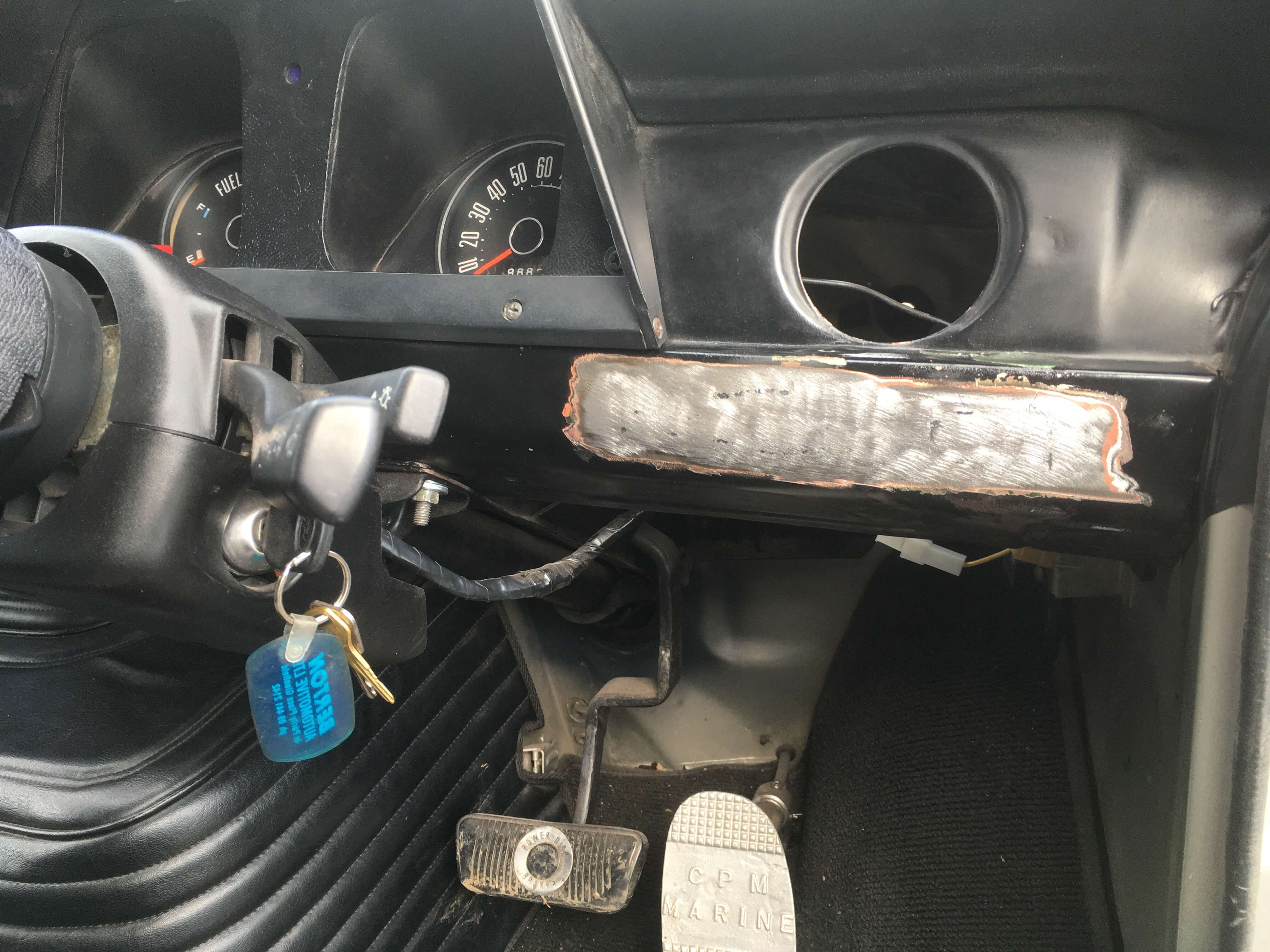
Remembering how hard it was to remove the pedal assembly from the old van (an axe was used, amongst other things) I opted to splice the hydraulic clutch bracket and pedal into the new van, drilled out spot welds, cleaned it, tig welded in place with regular cooling. Then painted and assembled it all together, as good as factory I'd say, also found an interesting item behind the dash hahaha. it will join the other 10$ in change and Condom wrapper I've found so far
2 points
-
Noice work bro..2 points
-
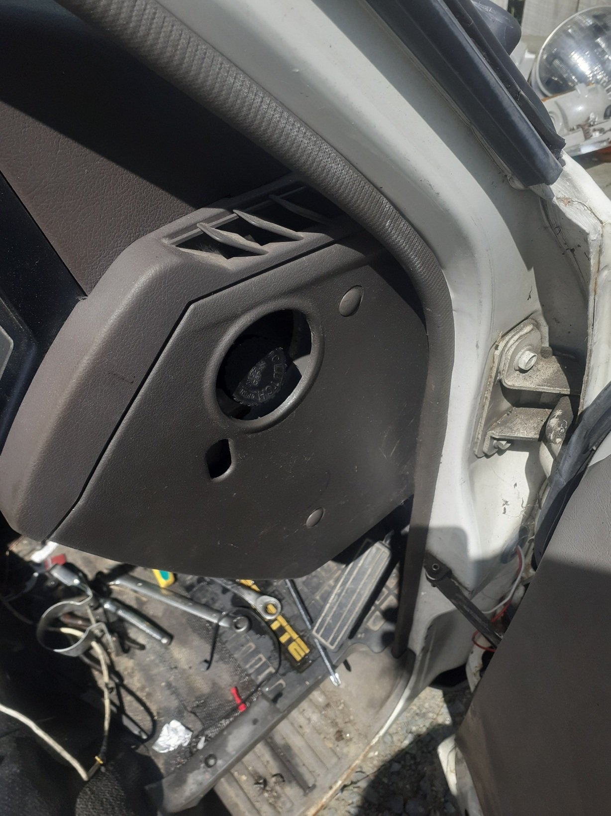
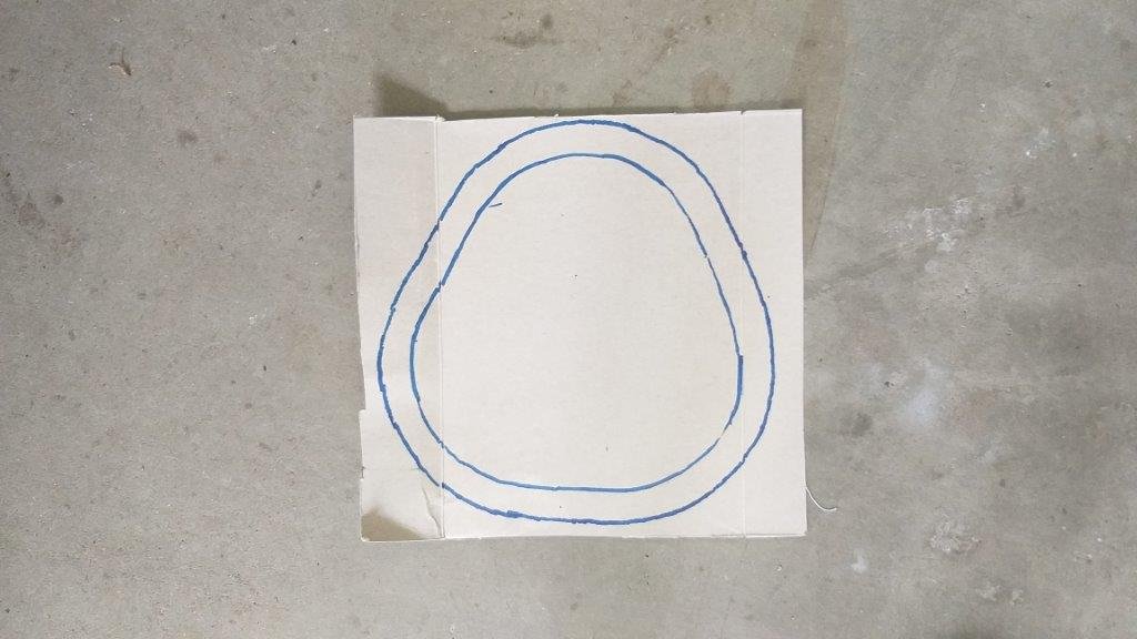
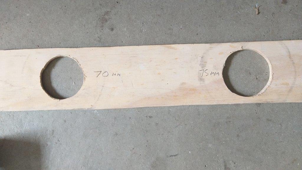
Merry Chrissy All from the team of one at Rough & Ready Restos. It being a special day I thought I'd treat myself to something other than cleaning crusty old Thames parts. Figured now would be as good a time as any to work out how I'm going to fabricate the floor plate that surrounds the steering and gear shift columns. My initial thinking is a solid plate with two holes cut out - one for the steering column and one for the gearshift column and then some rubber grommets to give me a weather seal. Started off with some basic cereal box aided design to get the rough shape of the plate. Next step was to figure out how big a hole I need in the plate to get the steering column foot through so cut a few rough holes in a bit of plywood. The magic number is 70 mm. The gearshift column is easier as it is just a straight rod. There isn't much room between the two columns so the outer grommet diameters will need to accommodate for that. My local rubber shop is having a Boxing Day sale tomorrow so I'll head along to get some pinch weld for my front doors and hopefully a few rubber grommets at the same time. Thanks for looking
2 points
-
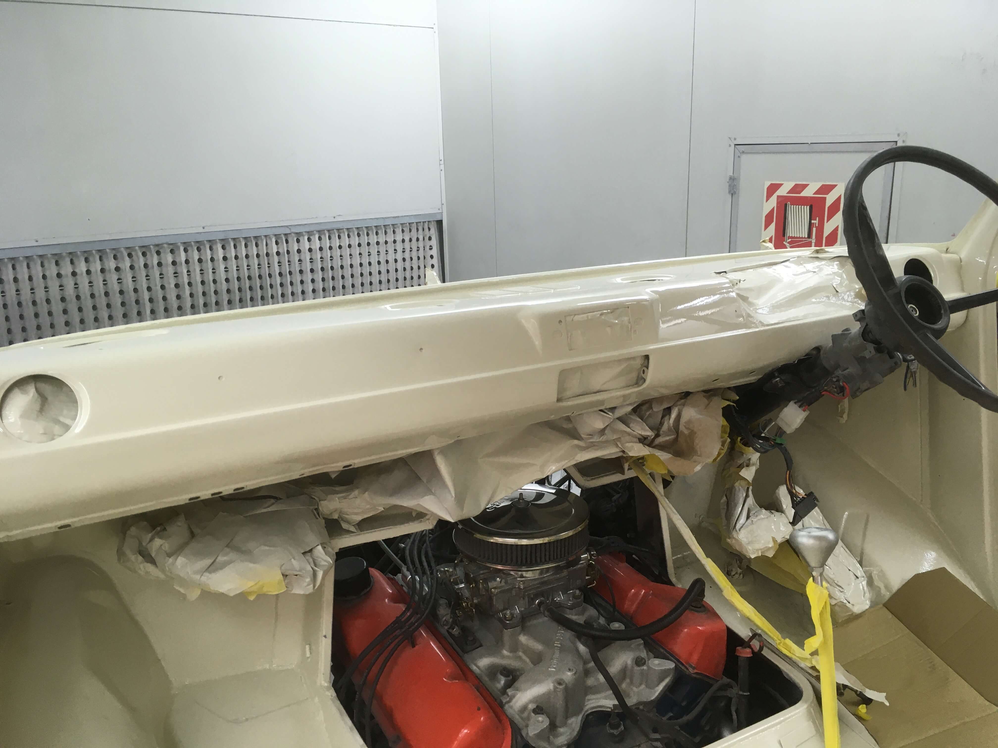
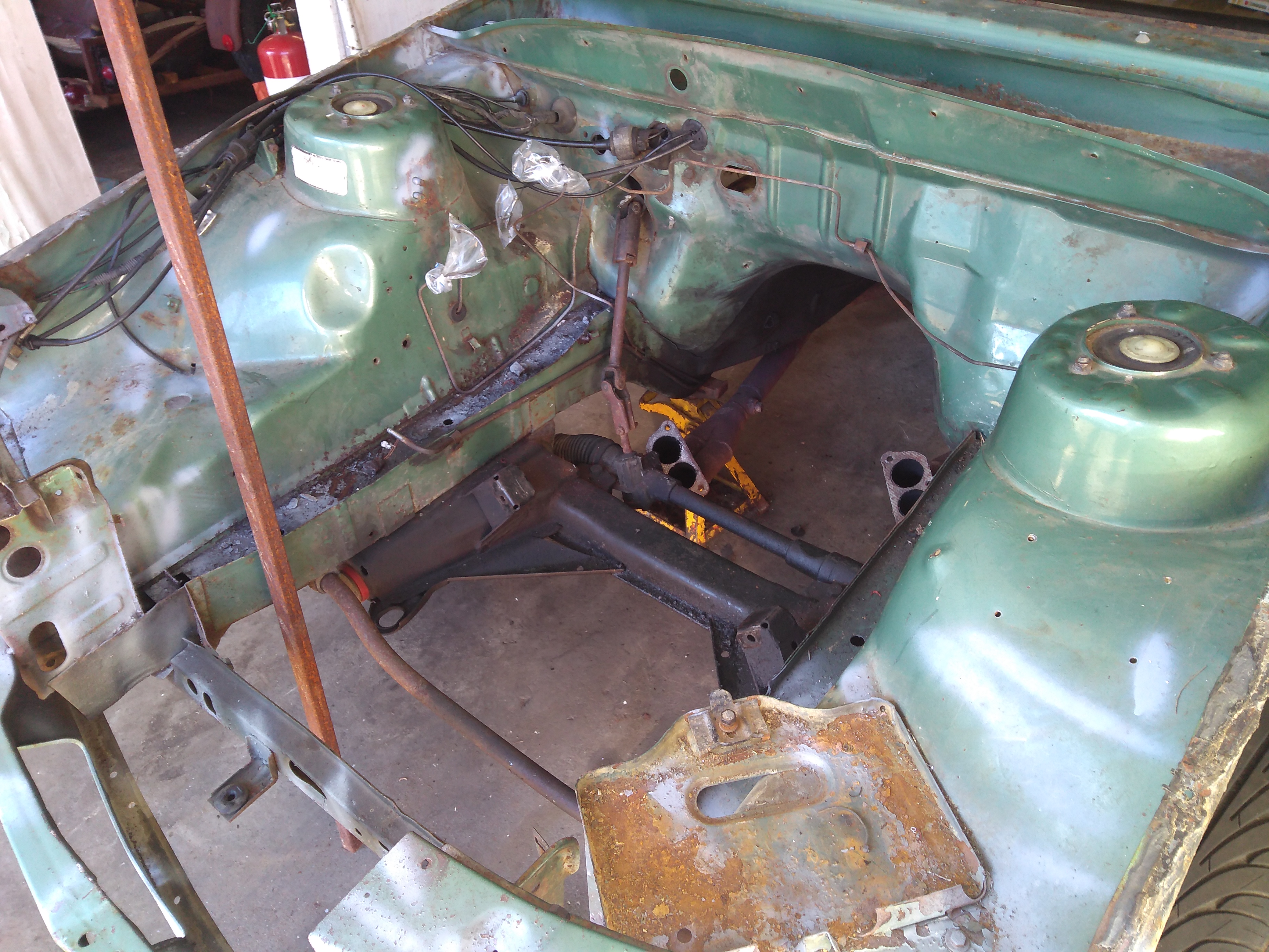
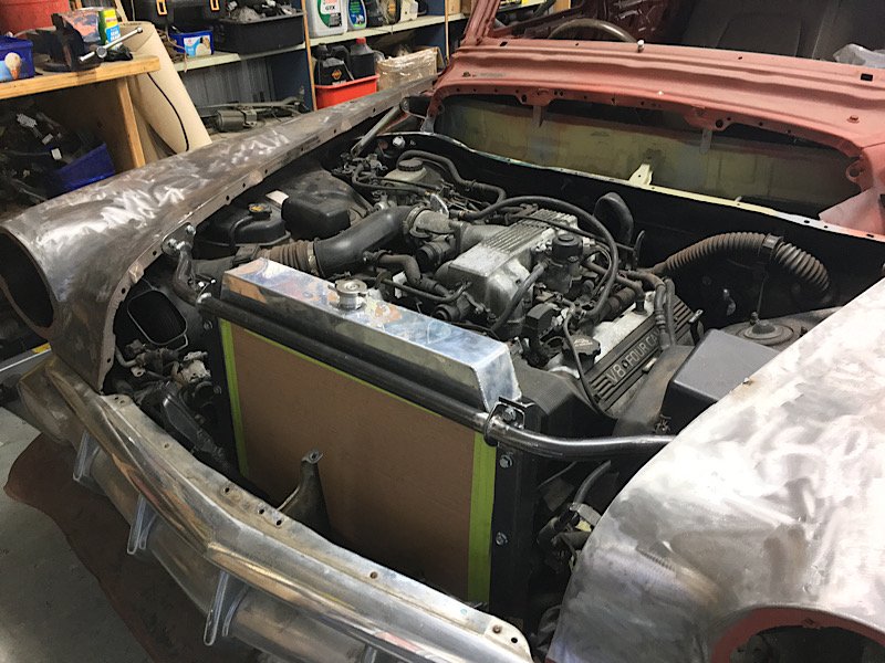
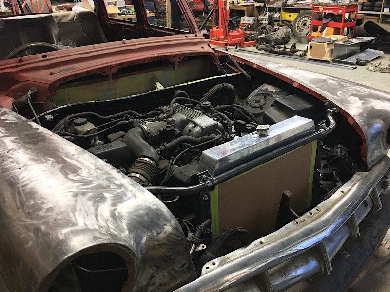
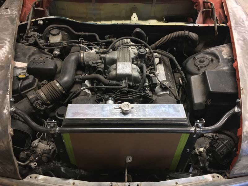
Just look at the difference... I am fully stoked - updated 29th December with latest photo to show actual engine bay comparison with subframe etc installed Before During After
2 points
-
2 points
-
2 points
-
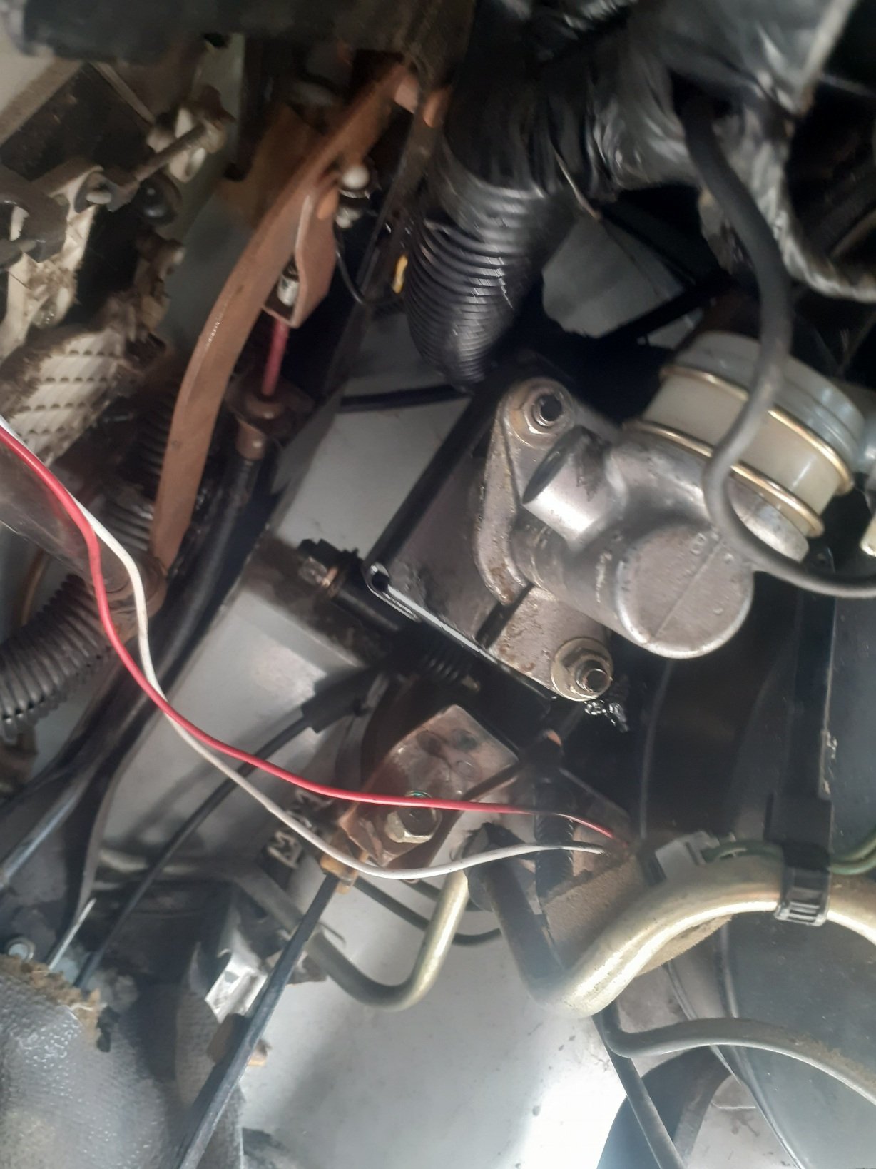
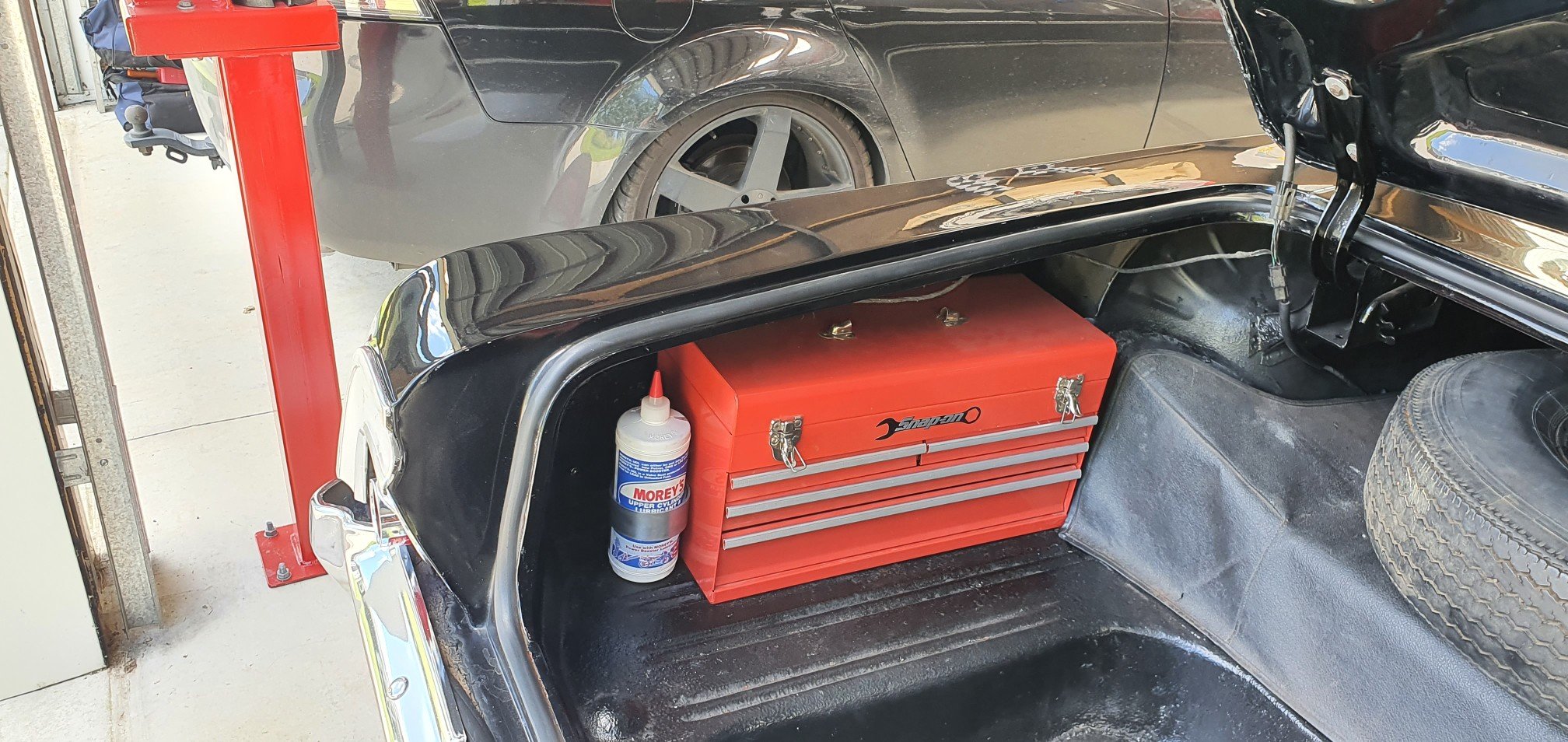
Another random project: Now I can get away from using those stupid valve master squirty things, that no gas stations appear to have anymore
2 points
-
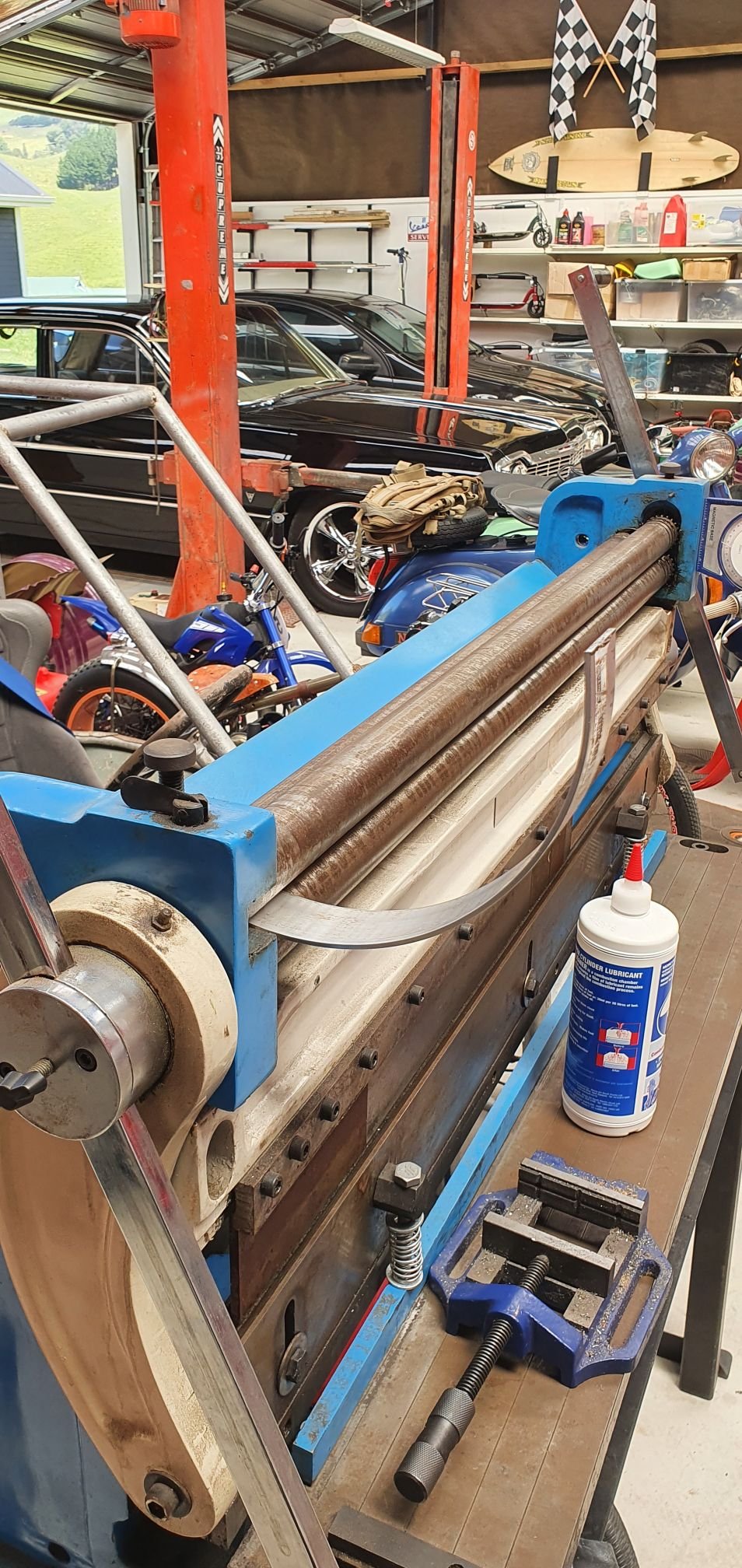
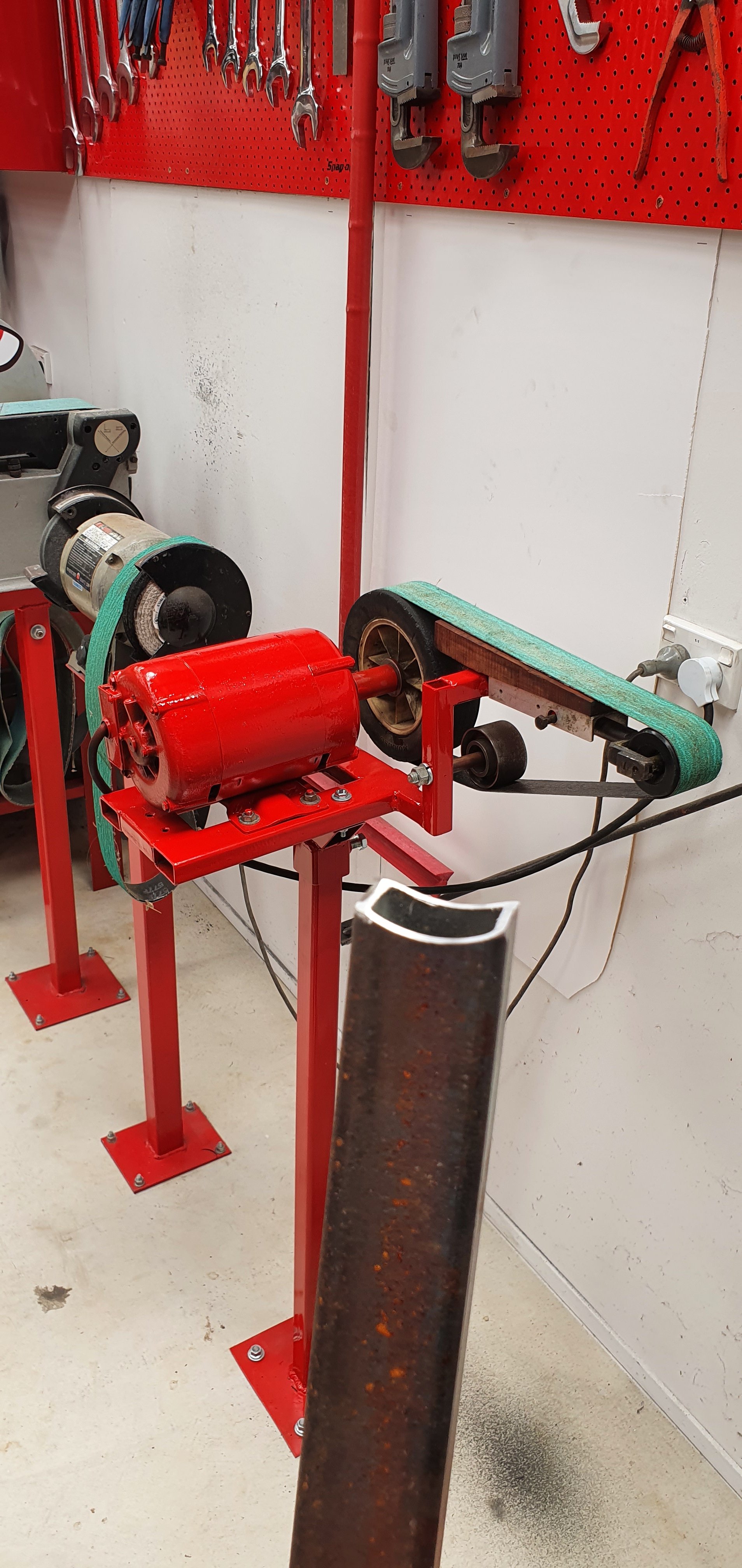
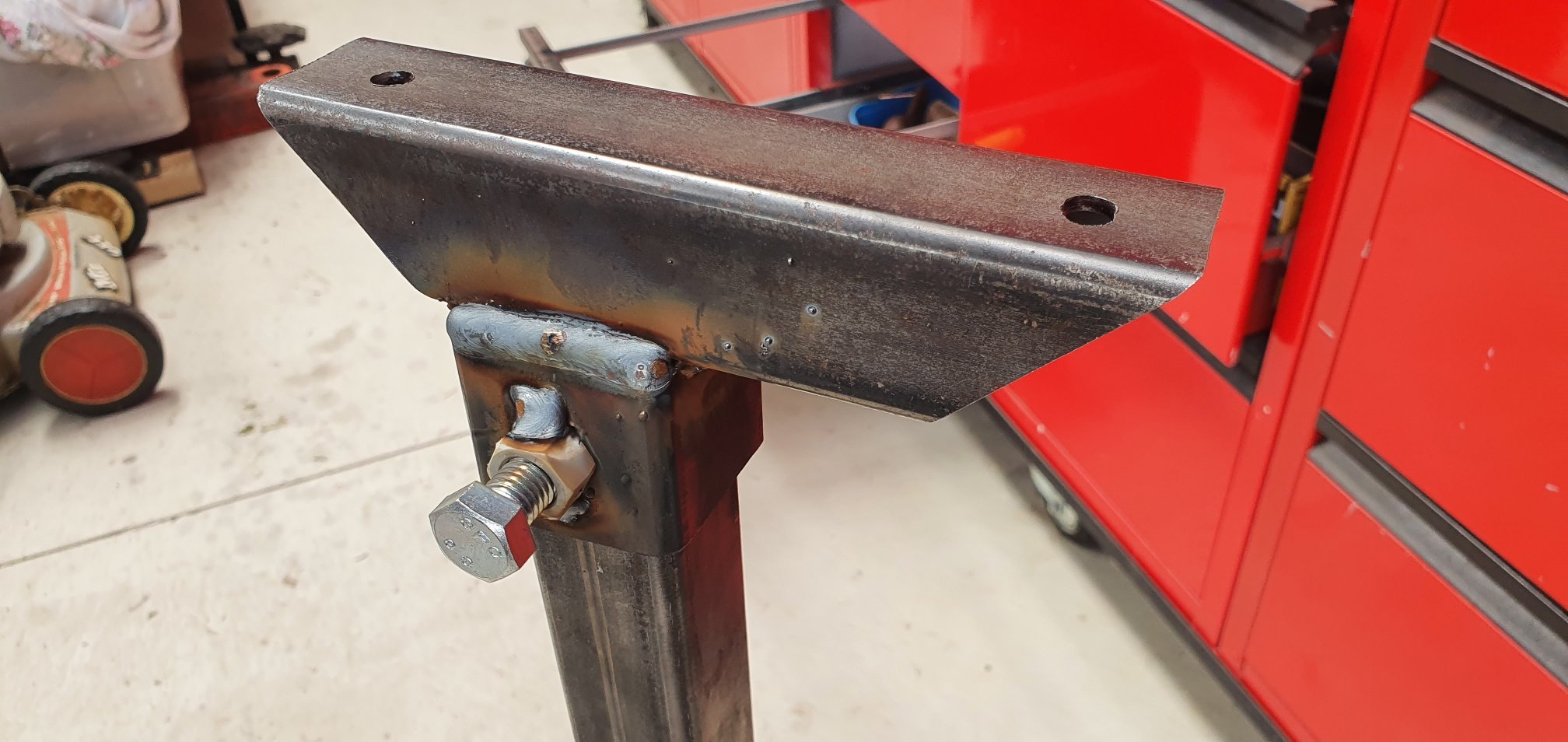
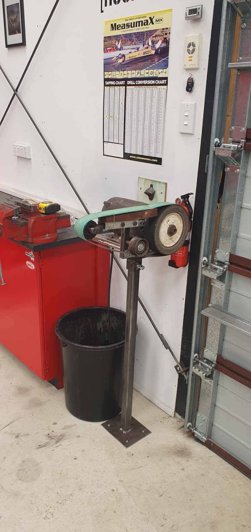
And a good opportunity to test my new linisher, see what its appetite for eating steel is like. Yip, it loves it!
2 points
-
Not finished...but you get the idea. I've made it so the top can move around in 90° increments, so you can use it in whatever position you need. Left, right, big wheel or little wheel etc...Paint to come next.
2 points
-
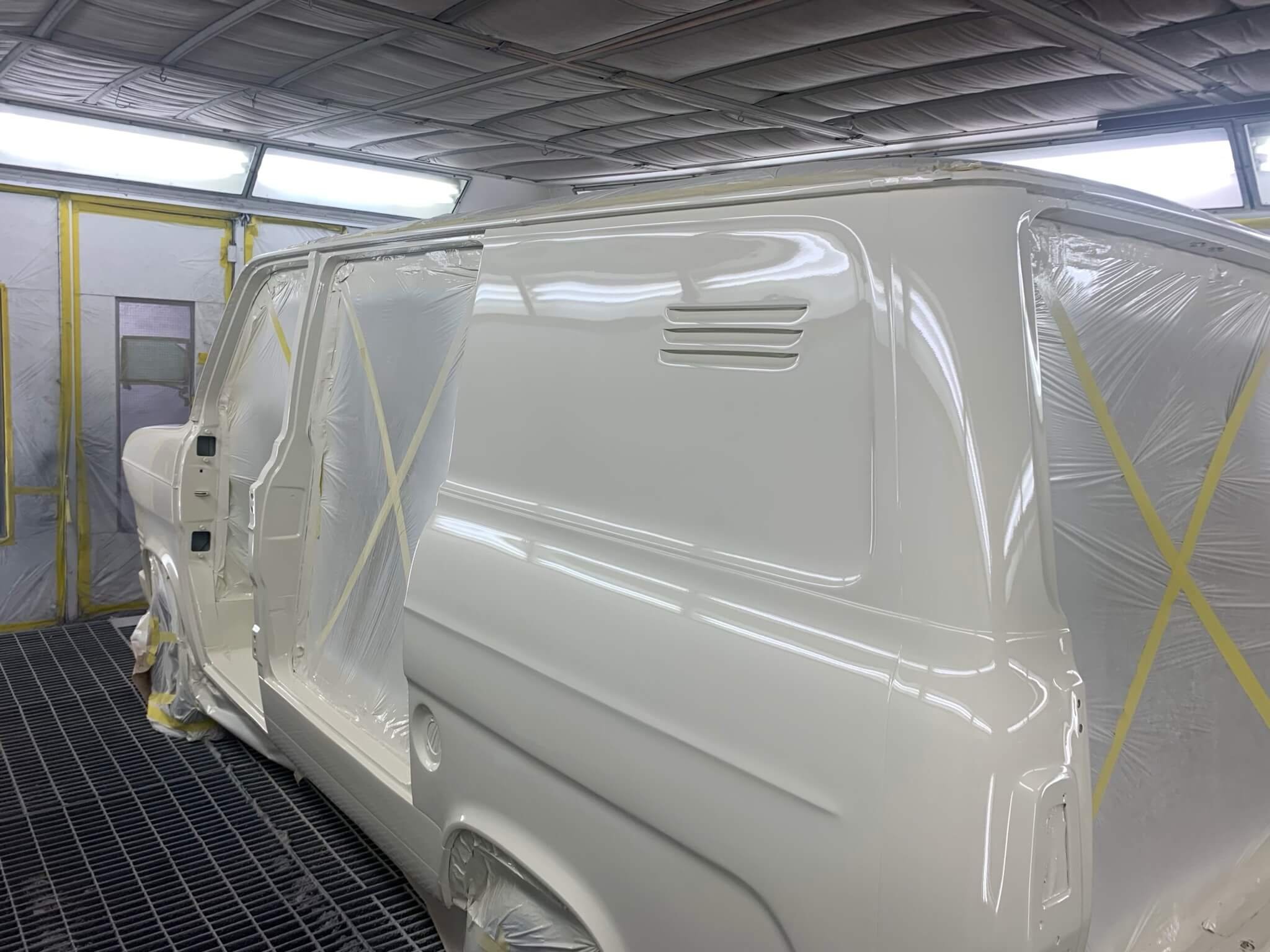
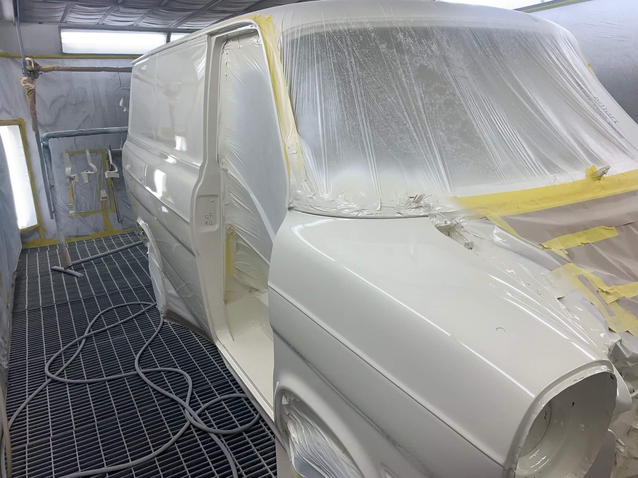
I checked up on the Mk1 yesterday. Panelbeater is doing a great job, and it is getting very close to final paint! https://oldschool.co.nz/index.php?/topic/45289-browndogs-1972-v8-transit/page/4/
2 points
-
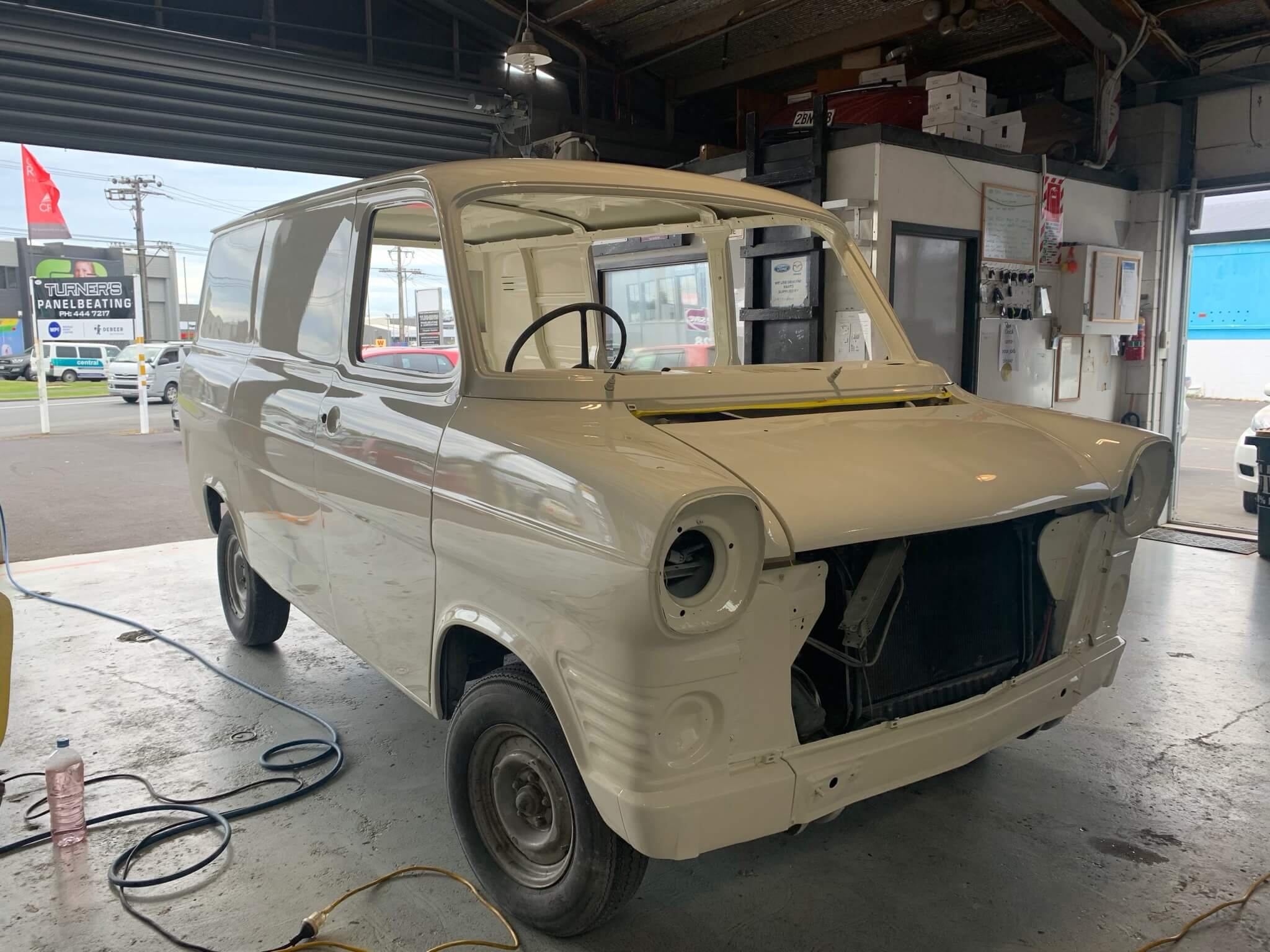
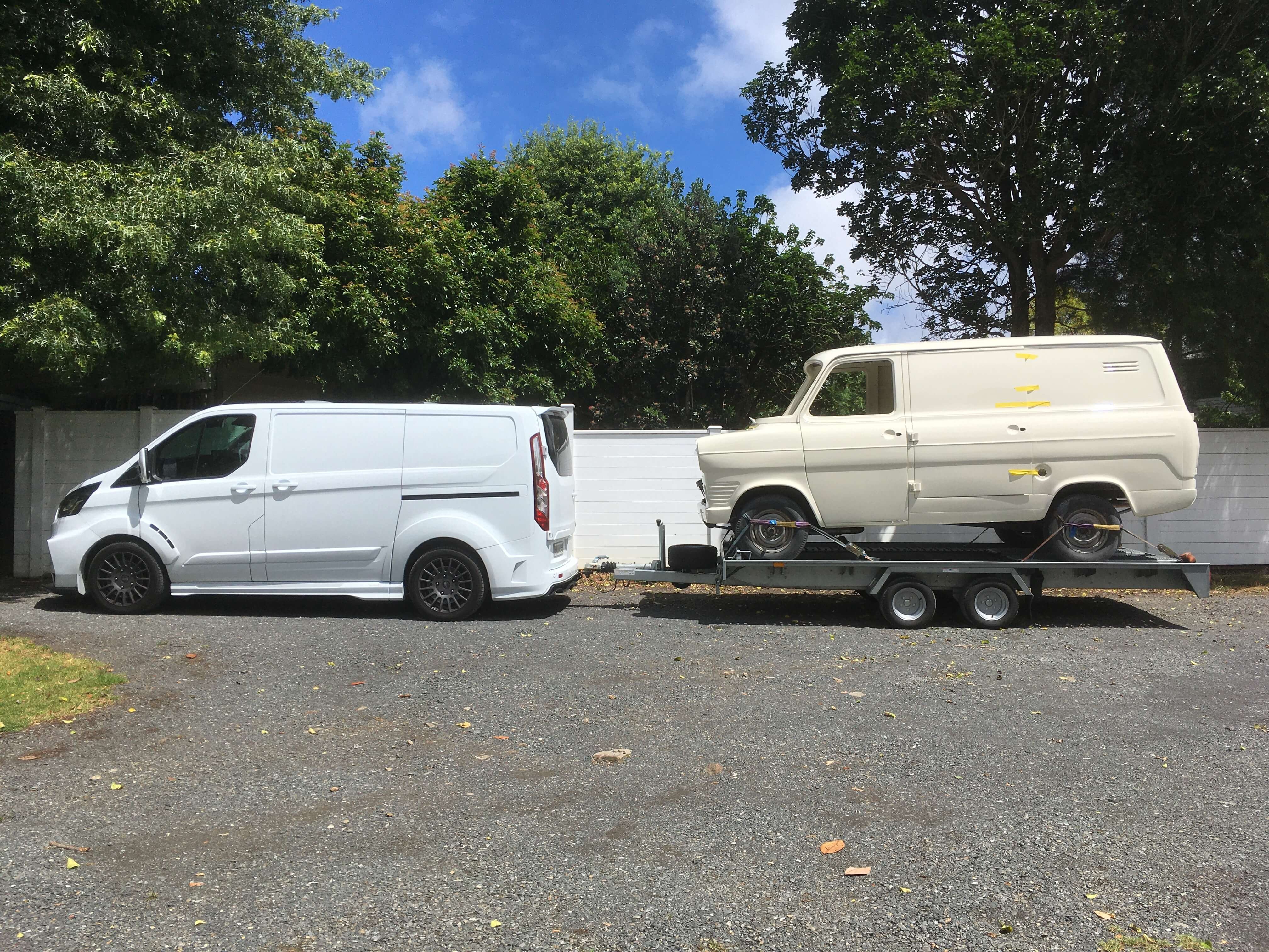
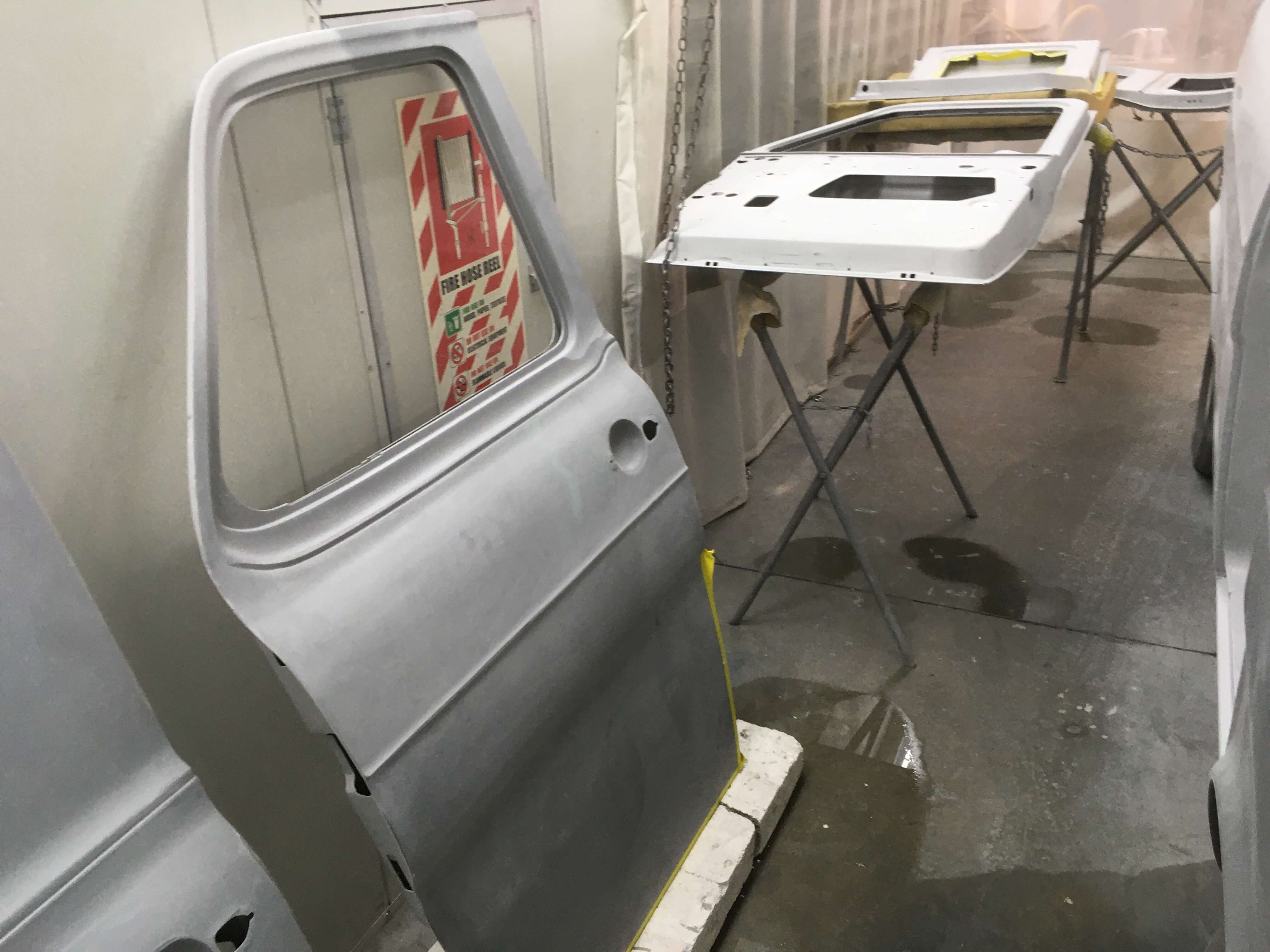
Picked up the Mk1 from body shop yesterday, super happy with the result! Need to strip it down, and deliver to the paint shop next. Some old switch holes in the dash welded up, I will repaint the whole dash. Did a quick test fit of the NOS tail lights in the new rear D pillars. Couldn't resist the last pic, 8th gen Transit towing 1st gen, that must make the Mk1 its great great great great great grandad! https://oldschool.co.nz/index.php?/topic/45289-browndogs-1972-v8-transit/page/4/
2 points
-
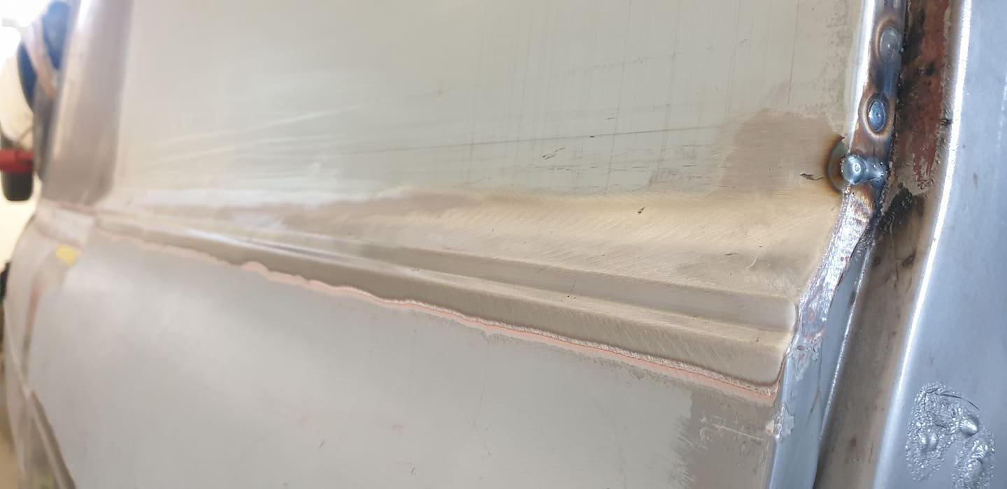
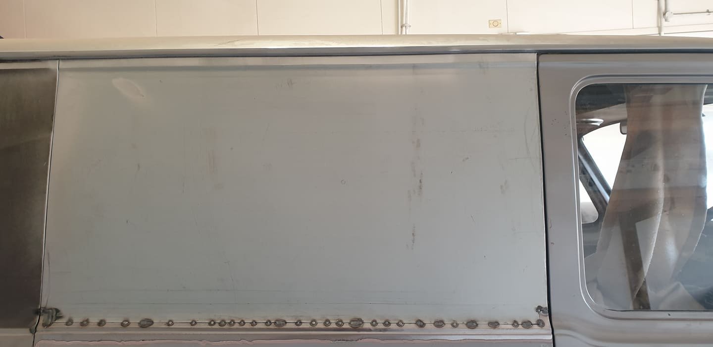
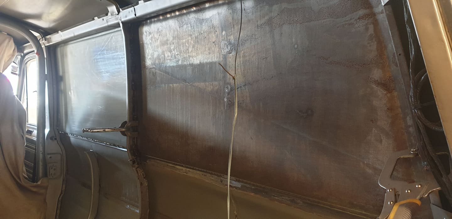
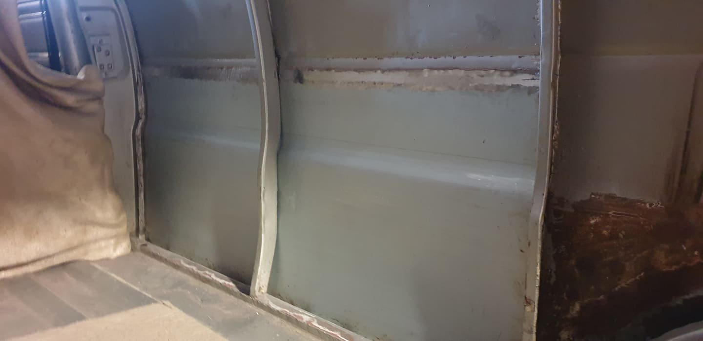
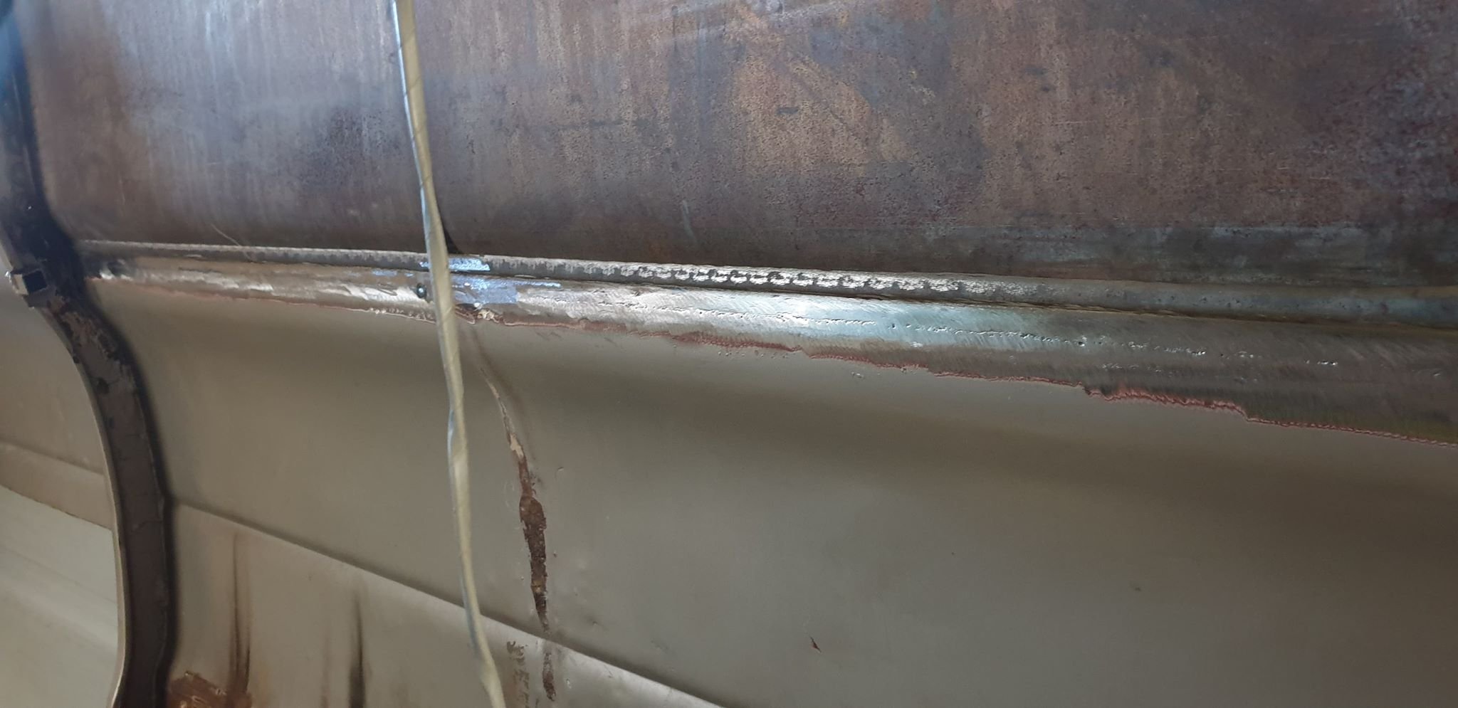
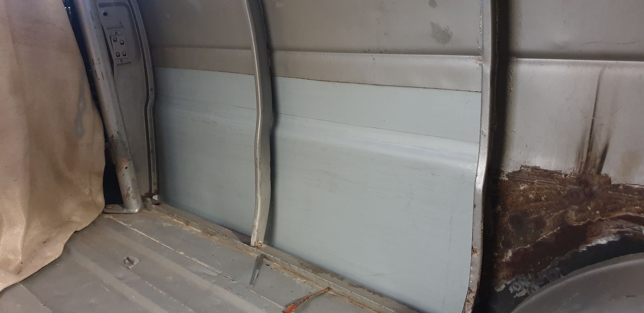
RHS all welded up now. Just a little sanding off welds to finish. Check out the detail on the horizontal bracing inside, those are new fabricated parts! https://oldschool.co.nz/index.php?/topic/45289-browndogs-1972-v8-transit/page/4/
2 points
-
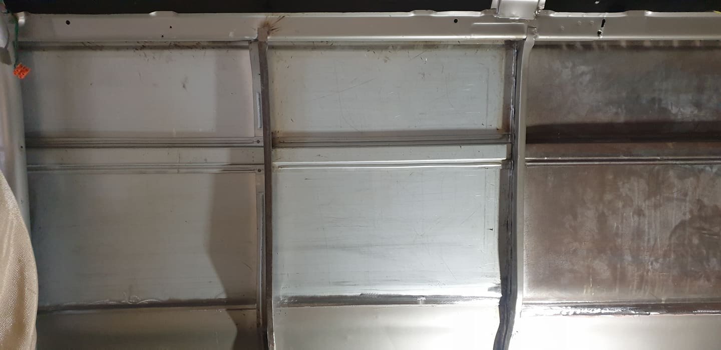
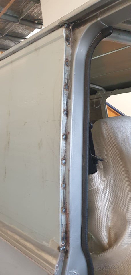
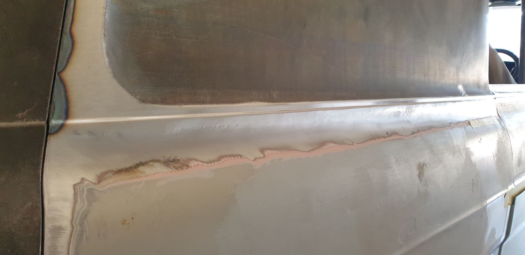
RH side getting there, panels tacked in and looking good! https://oldschool.co.nz/index.php?/topic/45289-browndogs-1972-v8-transit/page/4/
2 points
-
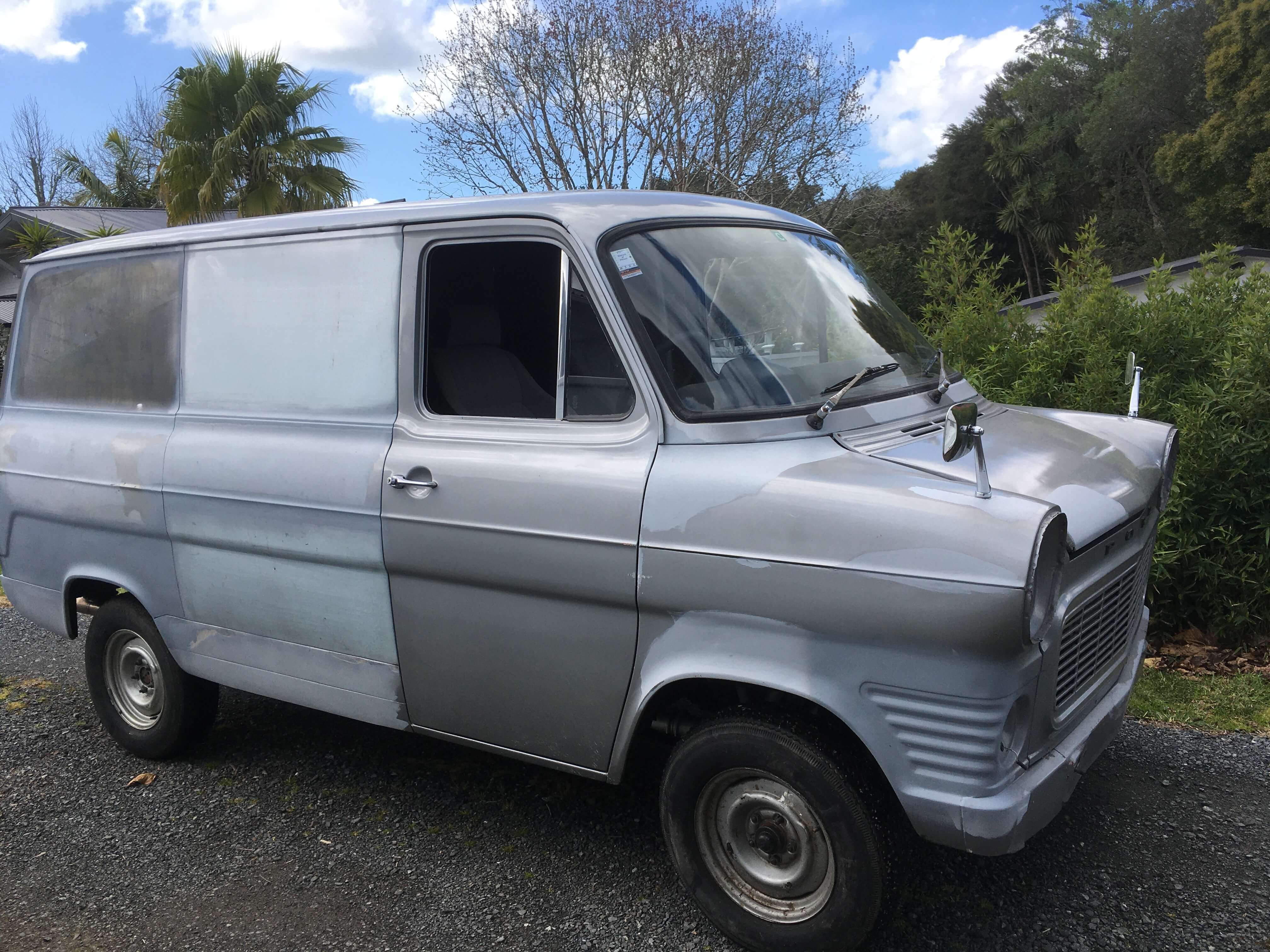
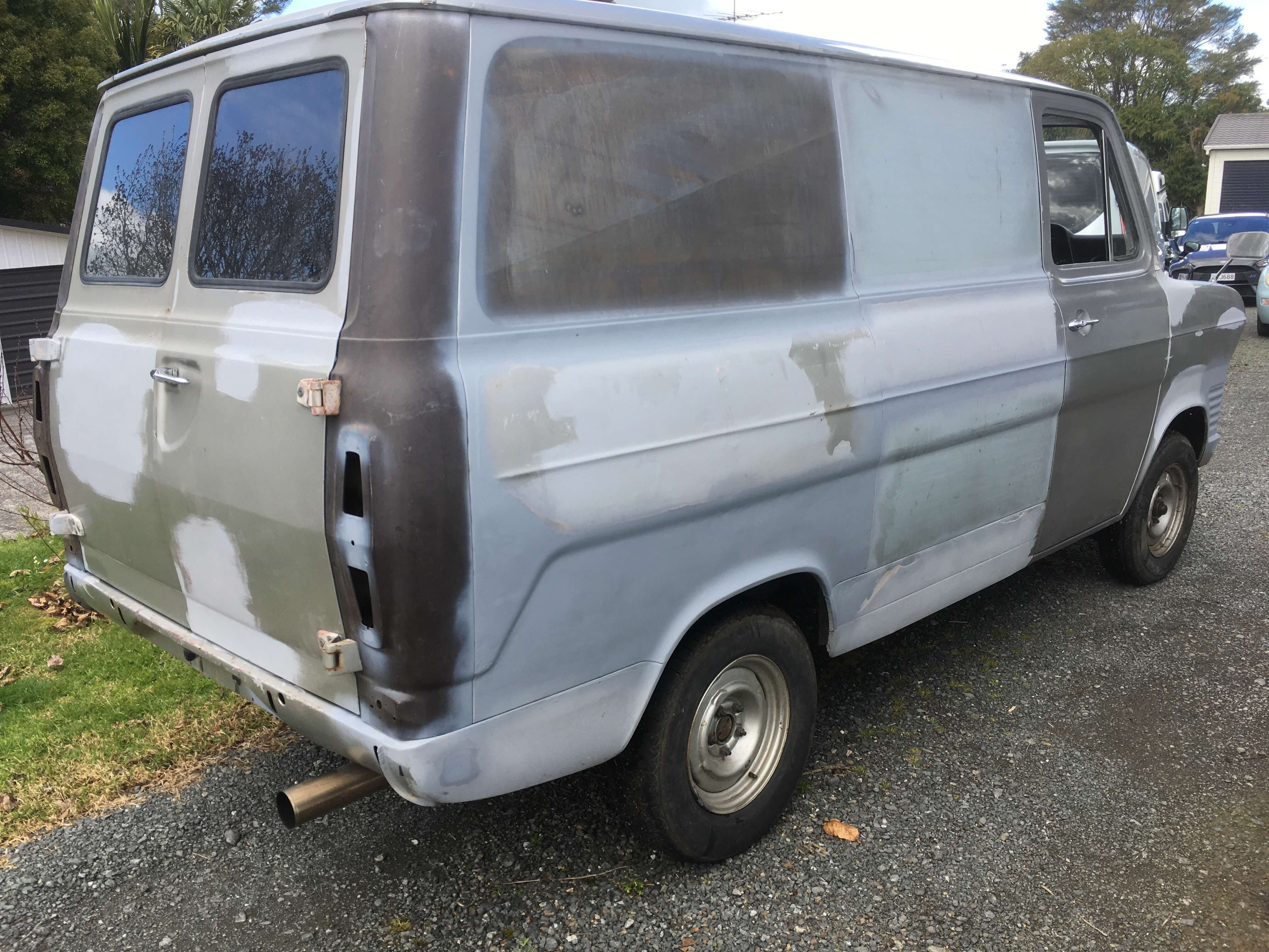
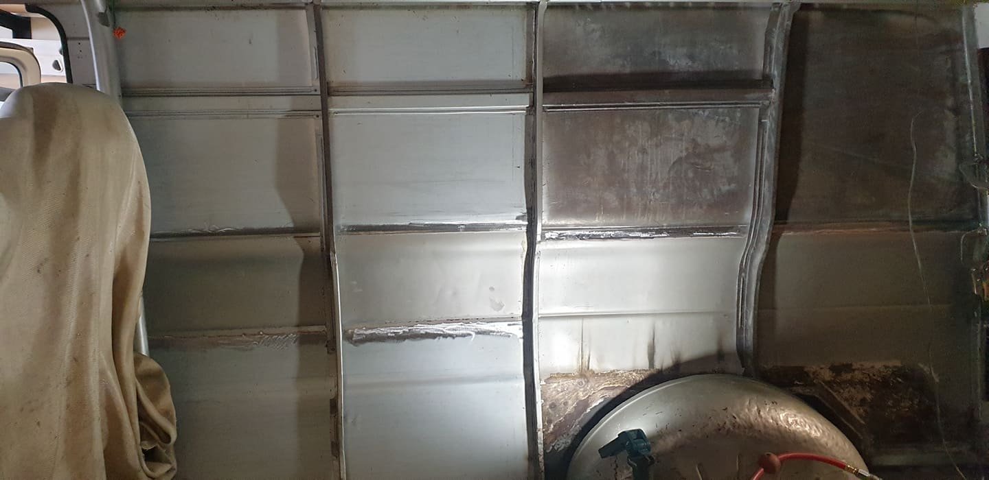
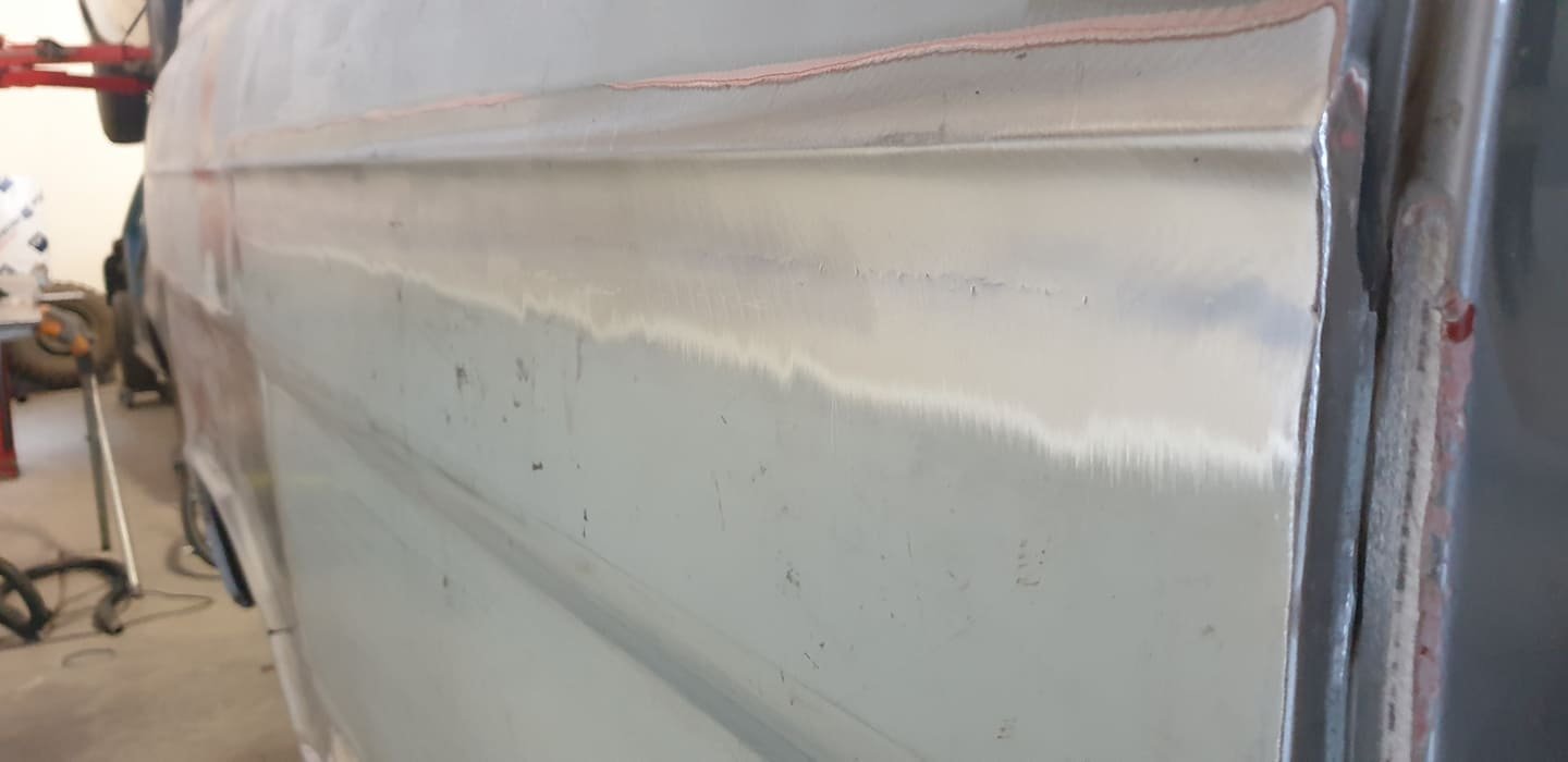
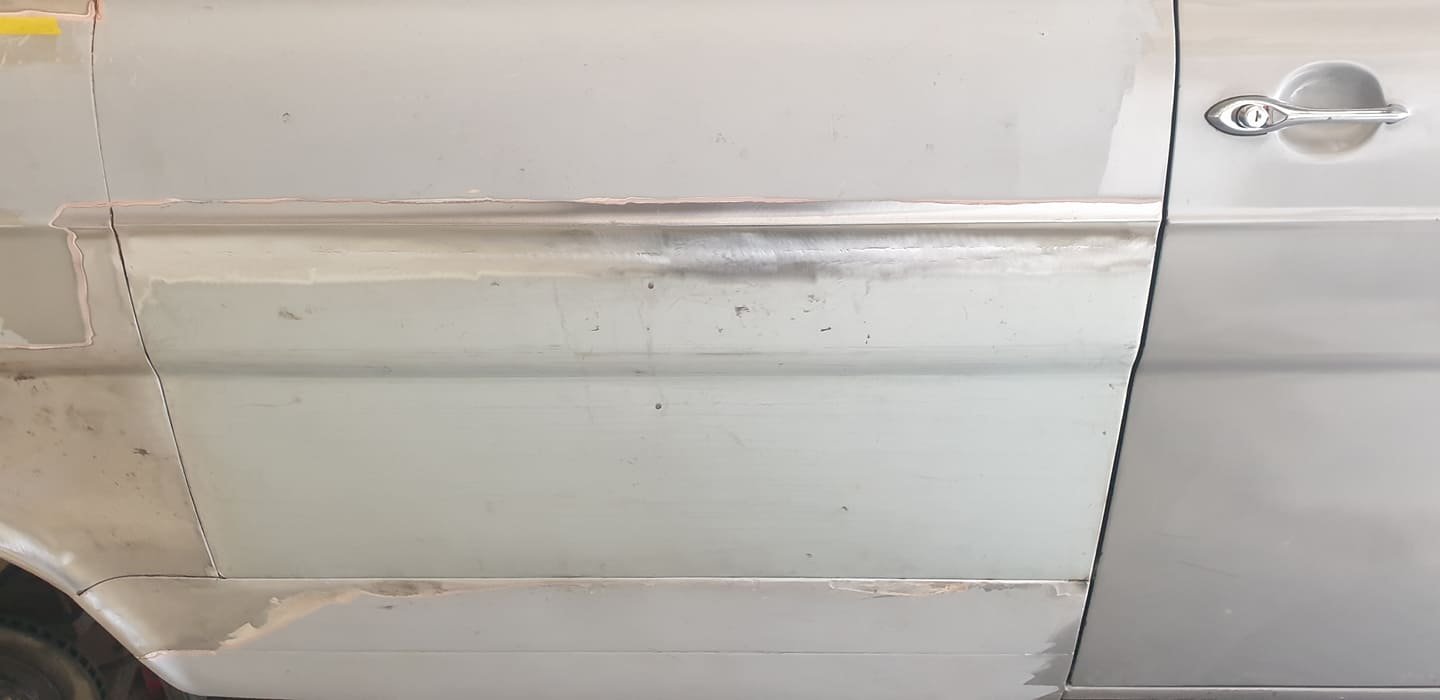
Some more progress pics. RR panel all welded up now. The mid panel, behind the drivers door had up t0 20mm of filler in places, and was quite stretched. So it was decided to cut this out and make a new panel. https://oldschool.co.nz/index.php?/topic/45289-browndogs-1972-v8-transit/page/4/
2 points
-
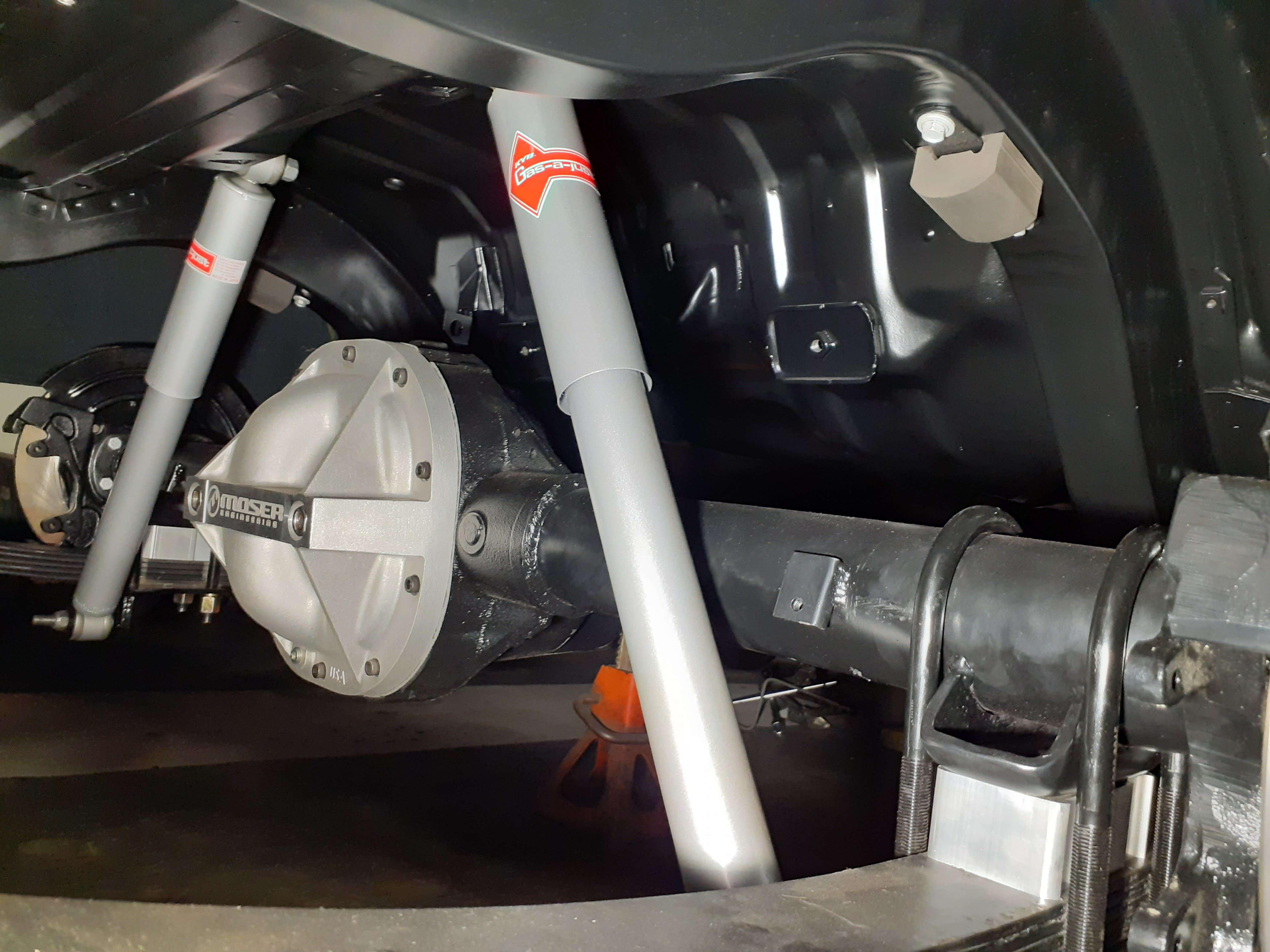
After getting my cushy posterior punished on Te Ureweras, i decided to look further into the suspension department. the rear has like 0 travel in those old shocks, might as well be hard tailed jim. So when a mudbug came up for wrecking on trademe, all i could think of was how cool this would look with those quintessential yellow springs on the rear. Took a punt and wanged them on. they are in average condition but what mudbug isnt? popped the standard suspension mount bushings out and swapped them into the mudbug shocks and was direct bolt on m9 country calendar theme plays2 points
-
Wow 250 for nos reflectors seems like a bargain now. Maybe inflation? Or I'm not as broke as I was?1 point
-
Looks slick, well done!1 point
-
Ive been looking at continuous mixers quite seriously. How I could make a small one etc. They are a horizontal auger with a center mixing section that have apposing and varying angled paddles. The resin is injected at a point a long the mix. If its a 3 part resin you do a pre mix (like you normally do). Ive used them at the foundries before and youre right about keep things clean. An initial un mixed amount comes out that you set aside (which you can throw into the pattern in the right place). Then when youre finished you have to do the same, keep running sand with not resin for quite a while. So even with a small mixer you would end up wasting a bit of sand.1 point
-
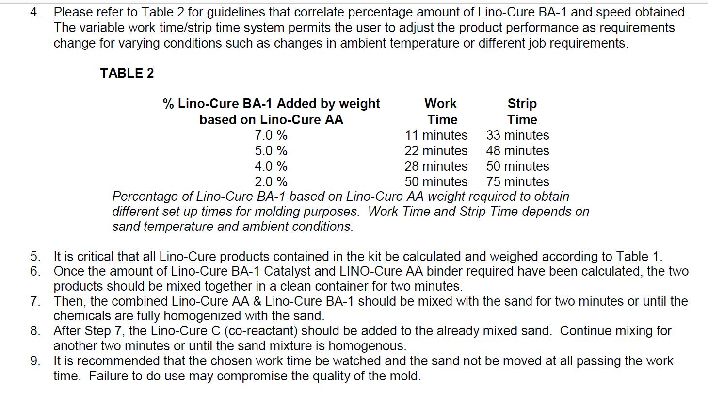
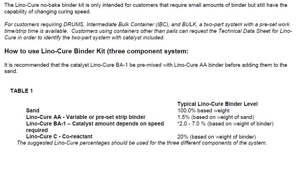
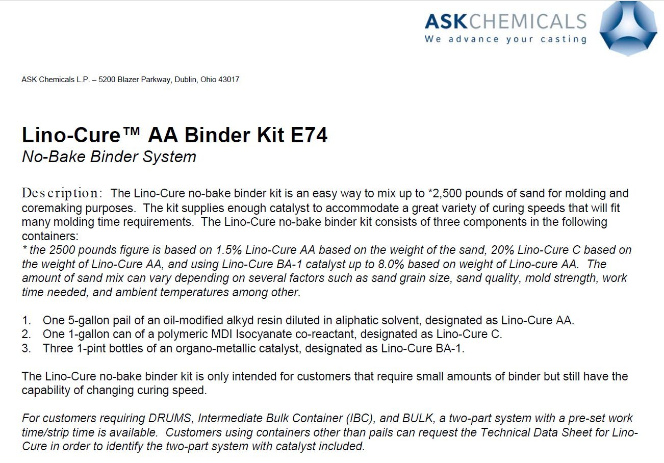
I have always used the kit, which contains 1.One 5-gallon pail of an oil-modified alkyd resin diluted in aliphatic solvent, designated as Lino-Cure AA. 2. One 1-gallon can of a polymeric MDI Isocyanate co-reactant, designated as Lino-Cure C. 3. Three 1-pint bottles of an organo-metallic catalyst, designated as Lino-Cure BA-1. The Lino-Cure no-bake binder kit is only intended for customers that require small amounts of binder but still have the capability of changing curing speed. For customers requiring DRUMS, Intermediate Bulk Container (IBC), and BULK, a two-part system with a pre-set work time/strip time is available. Customers using containers other than pails can request the Technical Data Sheet for Lino-Cure in order to identify the two-part system with catalyst included. I am not sure what the "pre-set work time/strip time" is for the bulk containers with the two-part system that they mention. I mix the "AA" resin with the catalyst "BA-1" first (this mixture does not harden), and then mix that with the sand, and finally mix the isocyanate co-reactant "C" into the sand. I use a commercial kitchen mixer for most of my mixing. For larger mixes, I could use a mortar mixing container and a hoe, but have not tried that. Some people use concrete mixers. So it gives a range of 2-7% on the catalyst "BA-1", and at the lowest amount (2%), that gives you 50 minutes work time. So it makes me wonder if you just left out the catalyst, and only used the AA and the C, then would the resin still harden, and if so, what would the working time be. I don't see anything that says you actually have to use the catalyst. I can mix up a small batch using the resin and co-reactant, and see what it does. It is a bit cold outside, so I would have to bring it in the heated shop to see if it hardens. I assume it would harden without catalyst, since I assume (perhaps incorrectly) that the catalyst only speeds up the reaction between the resin and co-reactant. The sand has to be very dry and clean, else the resin binder may not work correctly. .
1 point
-
The next step was to machine in some traction grooves. I came up with a few ideas in my head along the lines of using a small router with a carbide end mill mounted to the linear rail. But after realizing that could be quite expensive if I kept burning out end mills, I came up with a rather crude yet effective method, albeit extremely slow. I mounted a chamfer tool 90 degrees on the compound slide and ran it along the face almost like a shaper would, but slower. This seemed to work pretty well on the first test cut, so I carried on with this method, and used the same carbide tip for all 475 grooves (much cheaper than carbide end mills) When I say slow... Each groove took 7 passes to get a decent depth and a decent looking cut. One pass taking around 4 minutes, times 7 for every groove, times 475 grooves = 13,300 minutes or 220 hours. I had done well over half before the lock down in April/March - I then spent 10-11 hours a day for the first 7 days of lock down finishing it off. I tried several times to speed the process up, but that was the sweet spot with this method unfortunately. It also took some time to figure out the best quality cut. (blunt tip worked best in the end) There are a few cuts with tearing along the edges, but over all I'm happy with the outcome - it should do the job at least.1 point
-
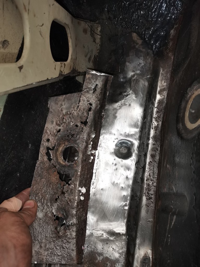
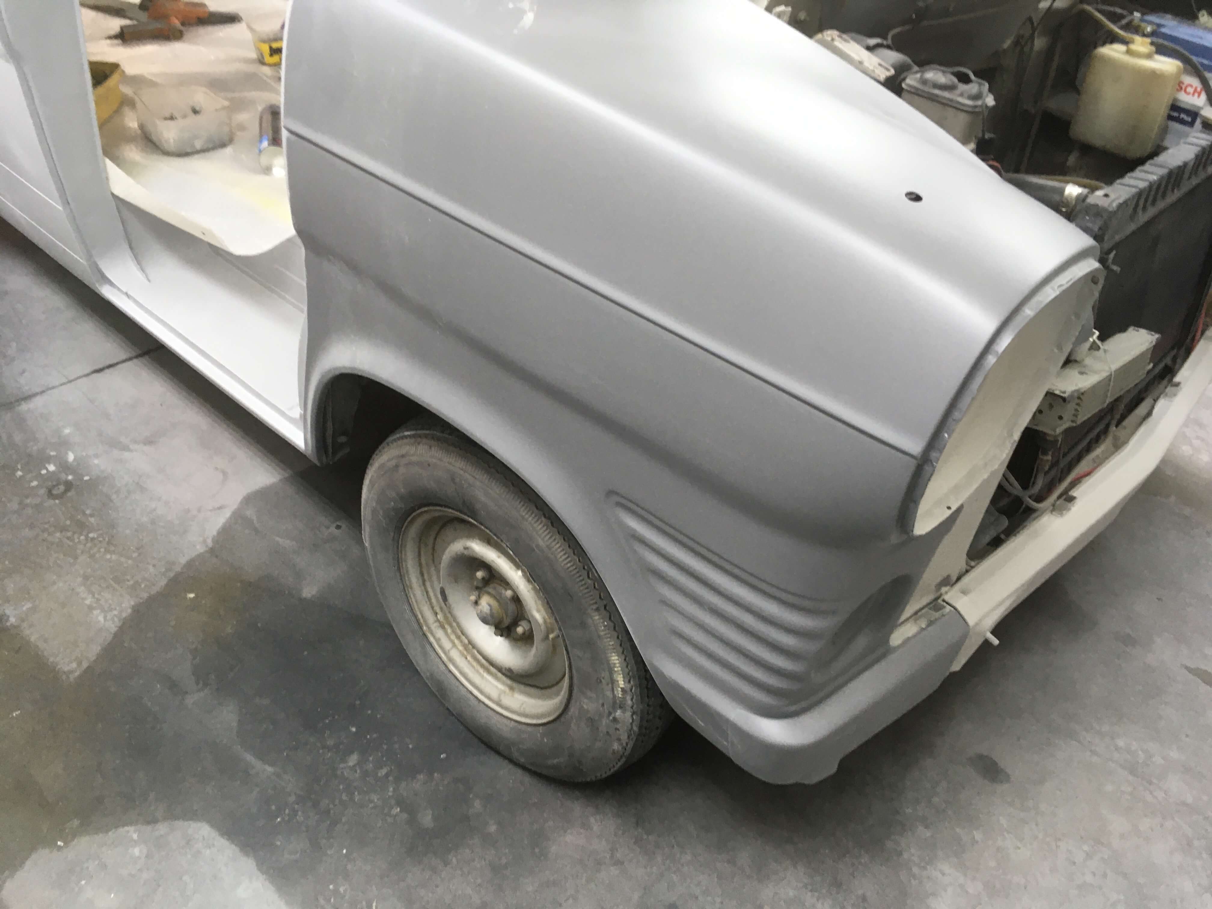
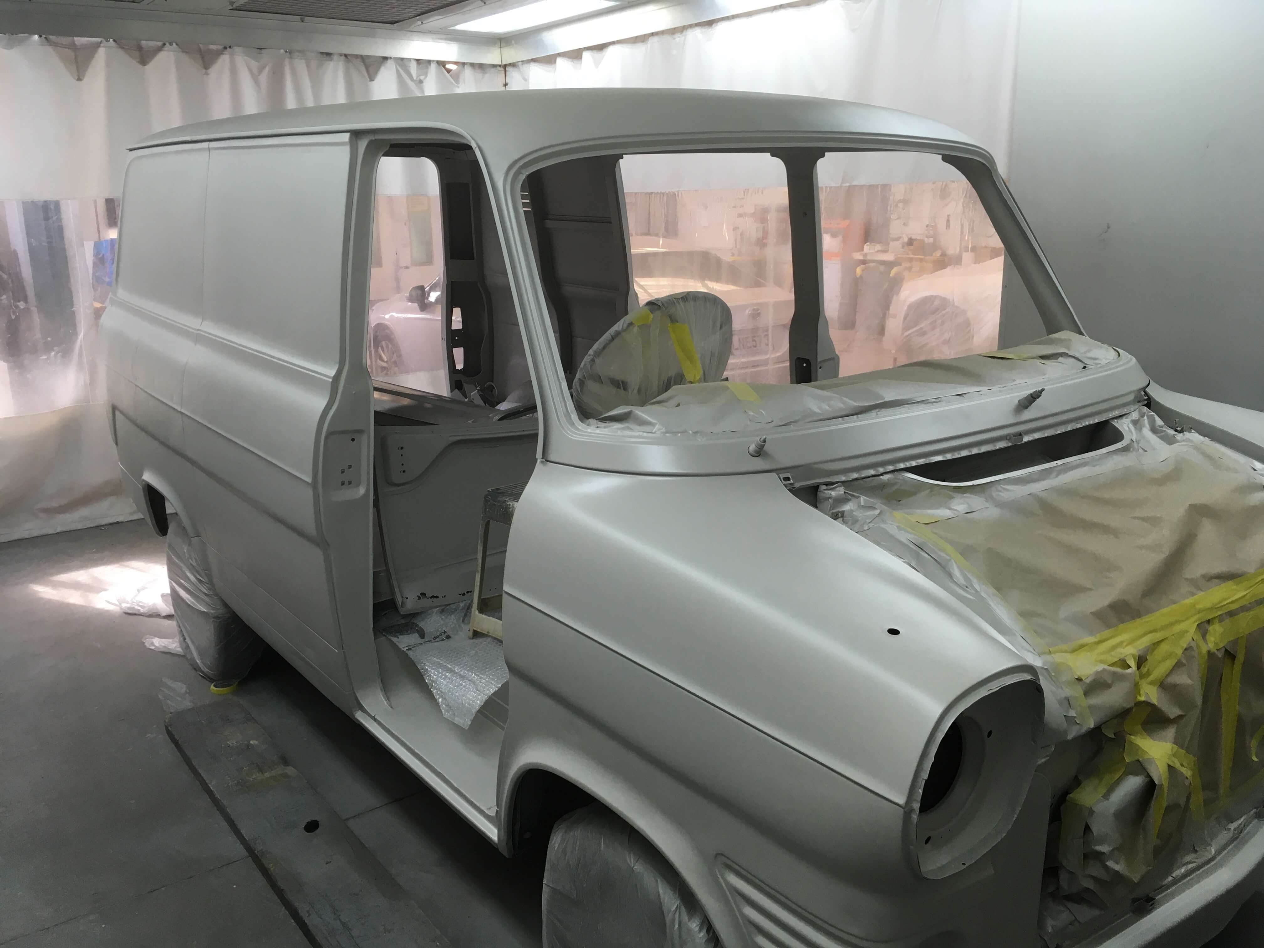
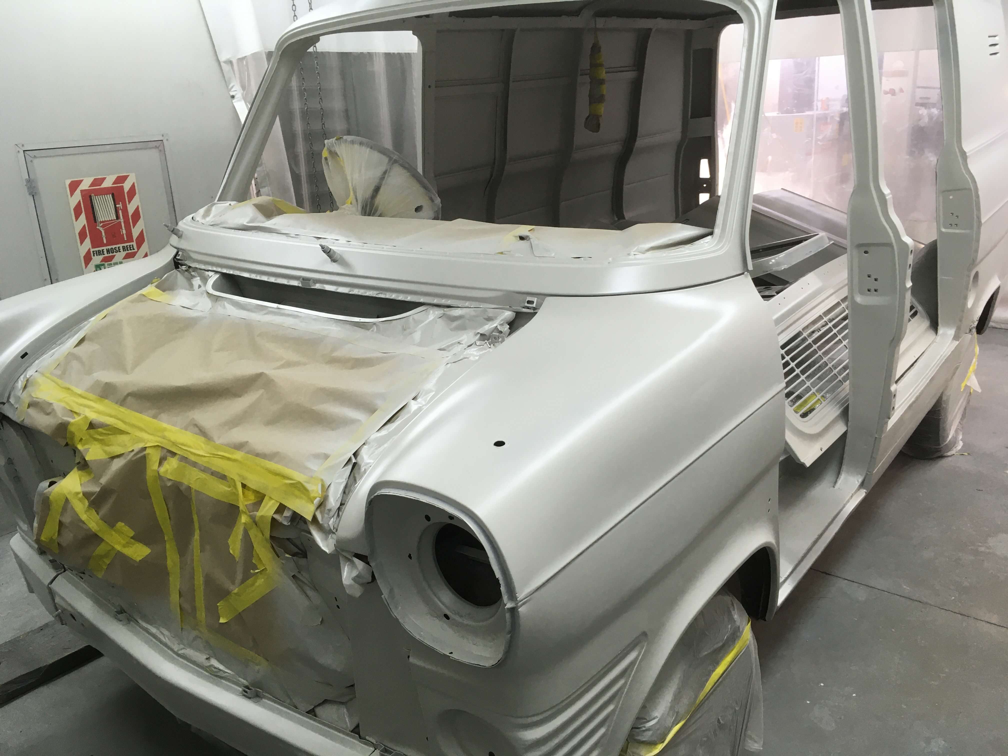
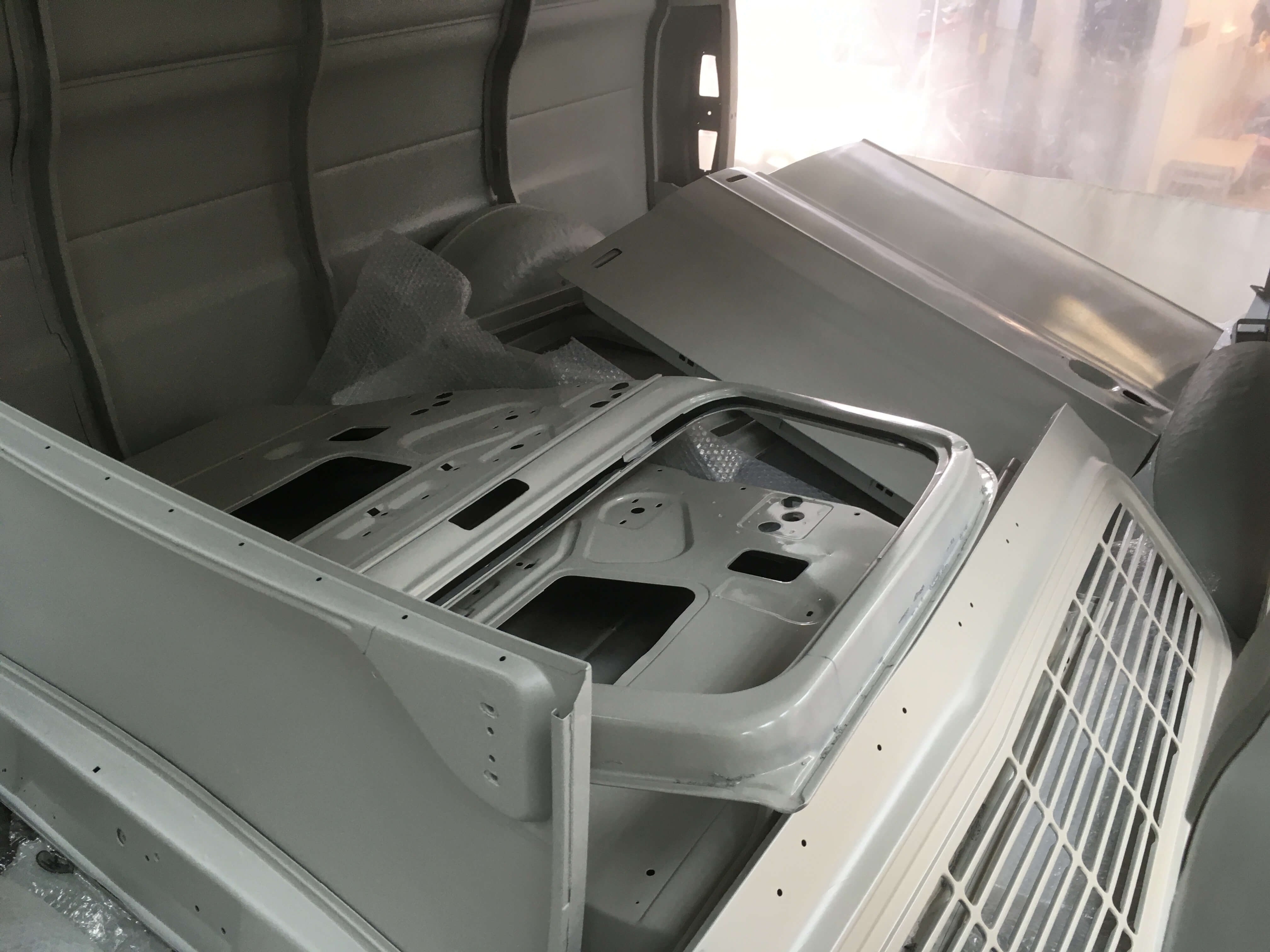
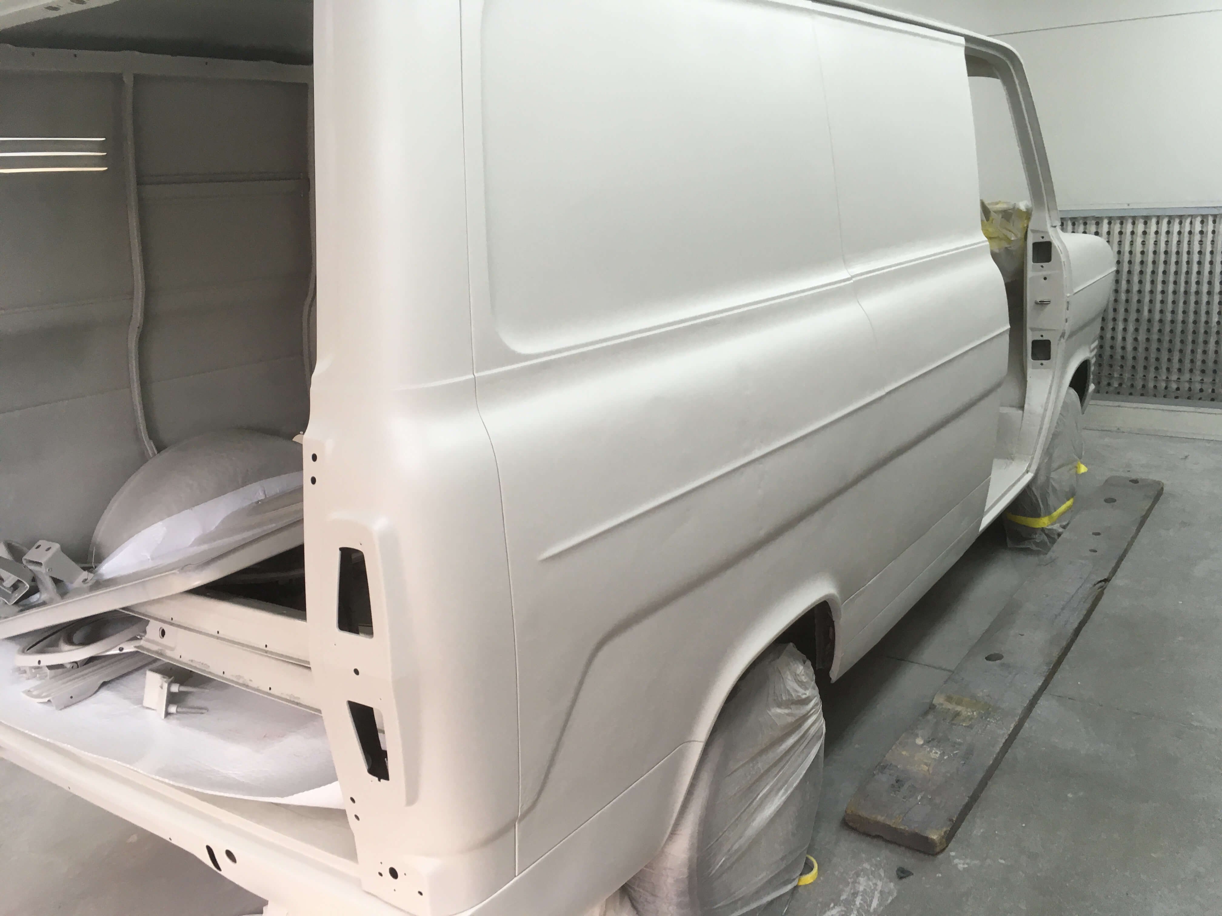
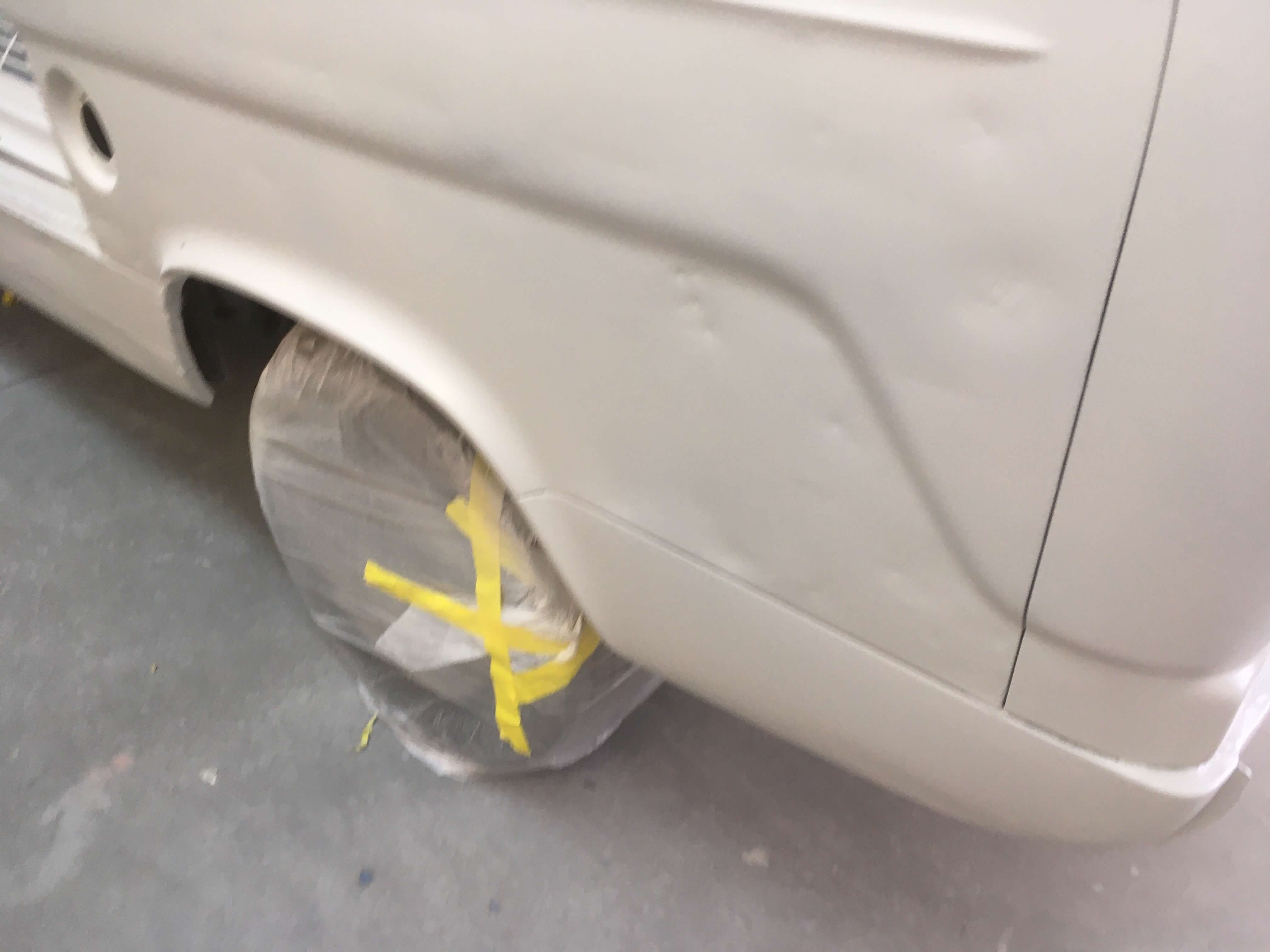
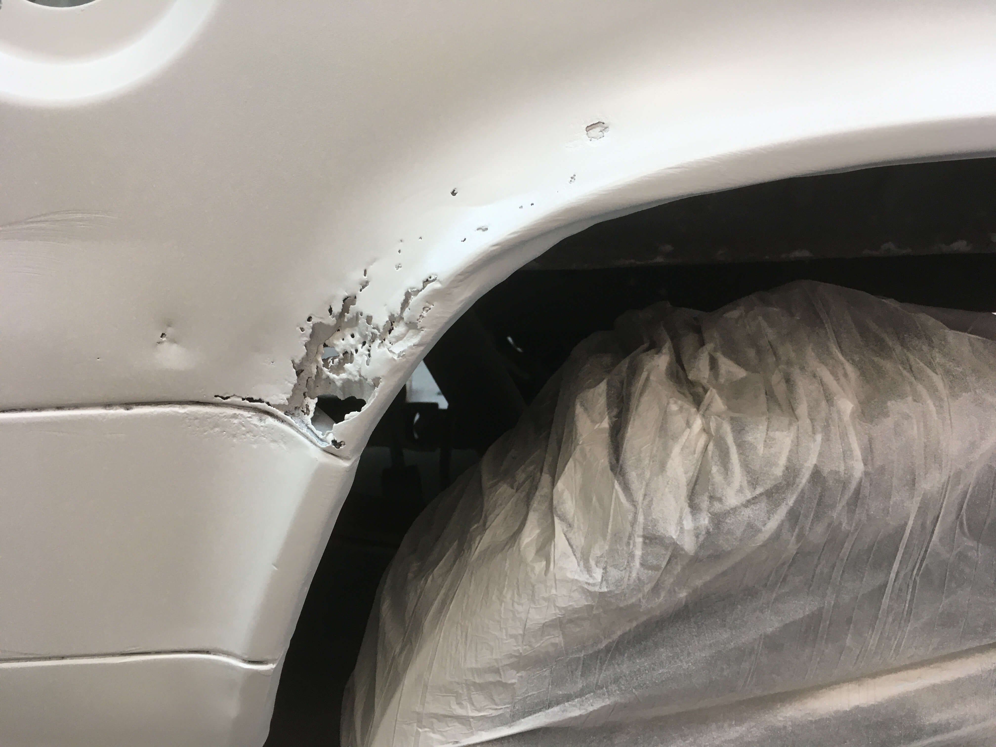
After delivering it to the shop for panel and paint, we decided that to do the job properly the van should be media blasted. There was still layers of paint and filler which had accumulated over the years (which would take days to strip off anyway) and blasting gets in all of those cracks and crevices where mechanical stripping does not. SO, another week or so later, another invoice paid, and the van was media blasted! I immediately took it back to the paint shop, hoping it would not rain on the bare metal, and a coat of etch primer was applied over all of the blasted areas. Fortunately the blasting did not reveal too many hidden nastiness. Mainly just one area around the fuel filler/left rear wheelarch where there was a hole and a lot of filler, so that will need a repair, as well as various small dents which will requite tapping out and some filler before paint is applied. https://oldschool.co.nz/index.php?/topic/45289-browndogs-1972-v8-transit/page/4/
1 point
-
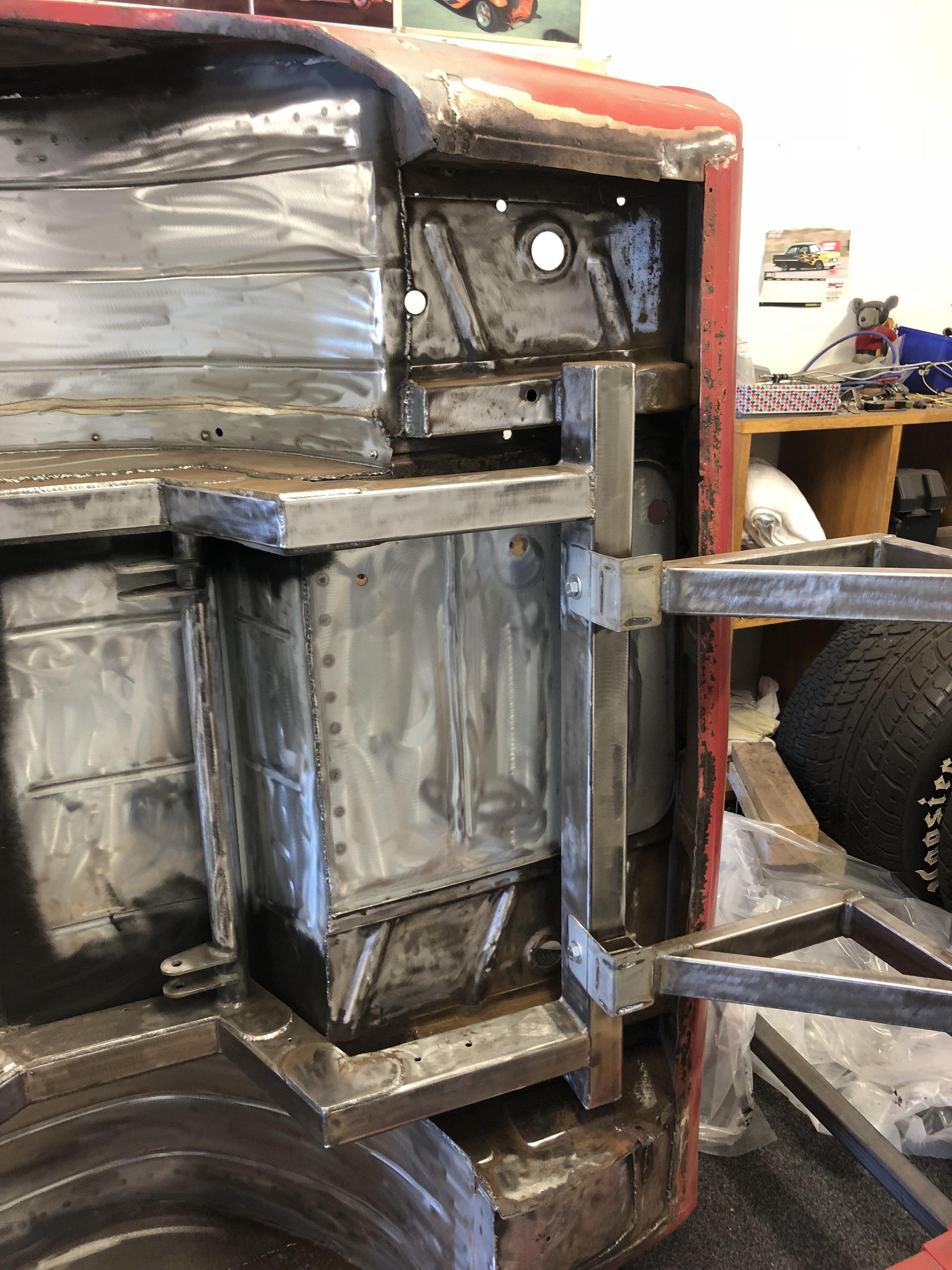
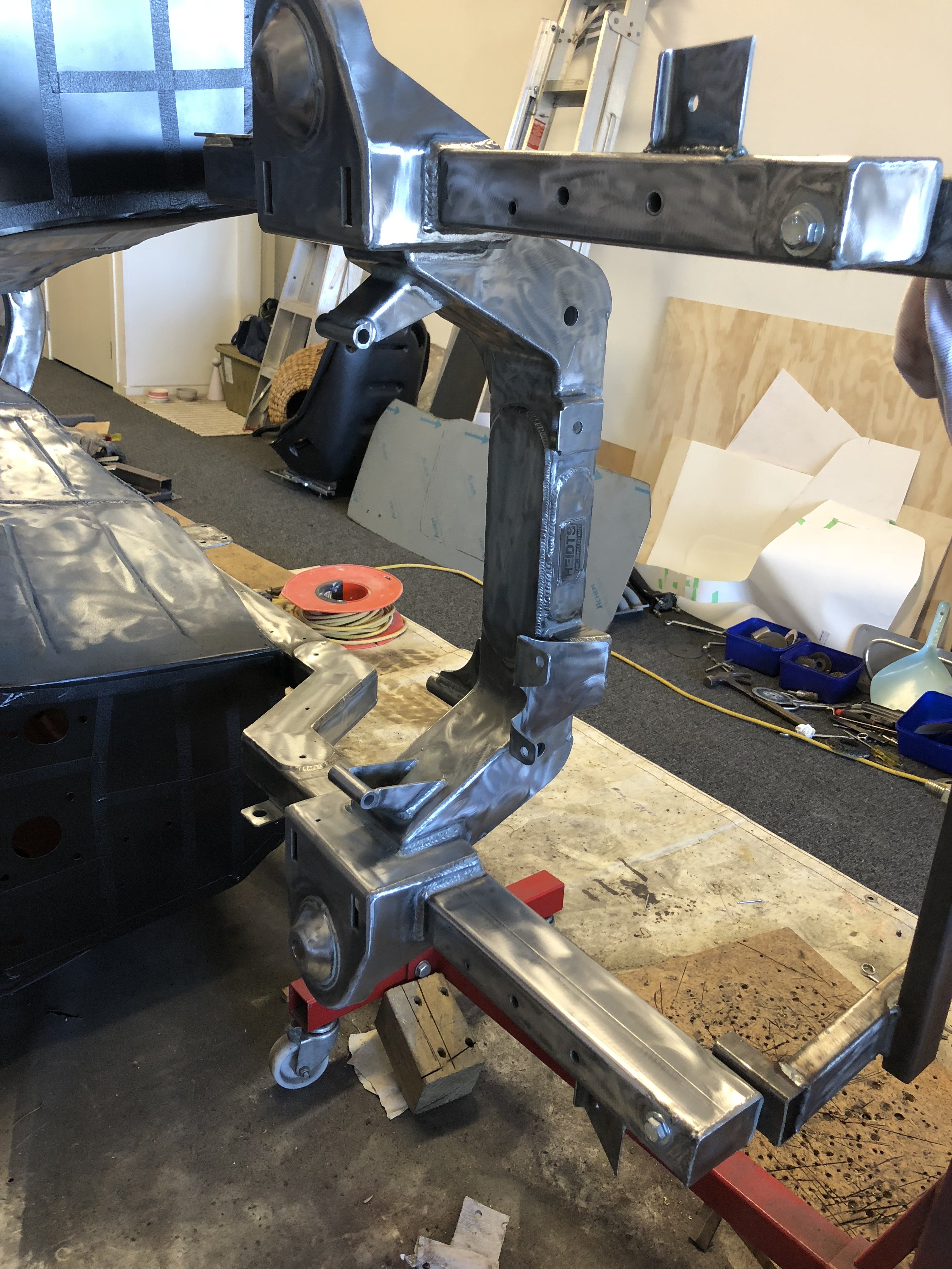
Spent the last few Weekends making a new front lower cross member and Radiator support bracketry. Radiator is a 1954 Chevrolet style aluminium one. It is 2-3 inches further forward now, and now the bonnet doesn't quite close. Should be easy enough to fix with some light trimming. Fitting a transmission cooler and a large enough battery is going to be fun.
1 point
-
https://oldschool.co.nz/index.php?/topic/45289-browndogs-1972-v8-transit/page/4/
1 point
-
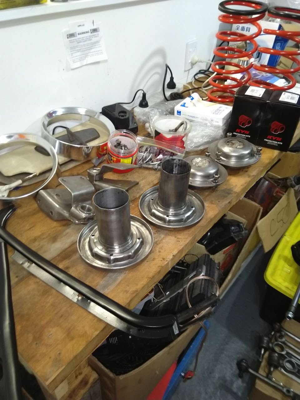
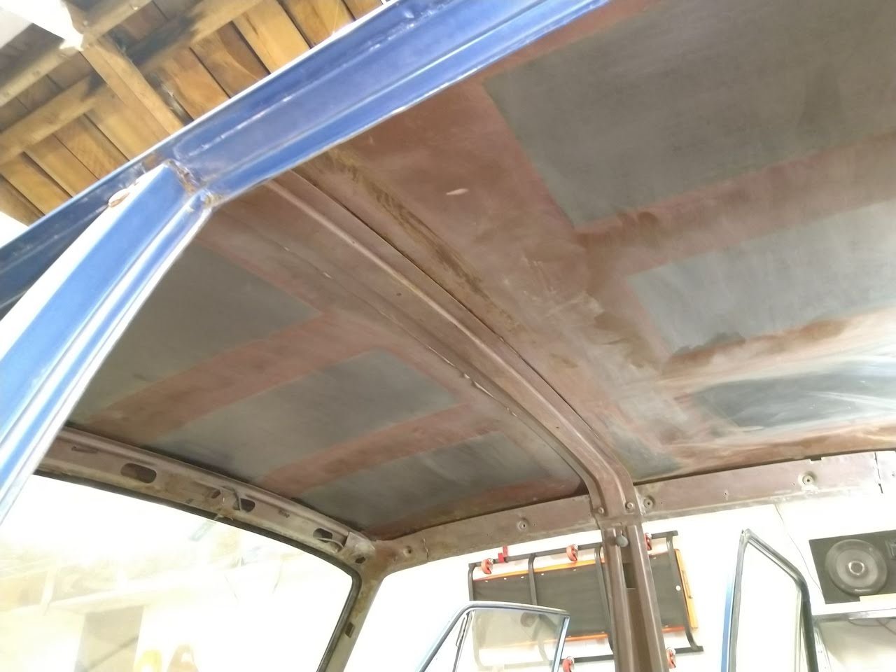
Haven't forgotten about this. I got the shocks converted to gas strut, pretty hapy with them so far. Been bare metalling all the other front suspension bits, will paint with epoxy primer and 2K black once it gets a bit warner. Also removed all the sound deadening from the roof. Wee bit of surface rust, nothing too serious. Will clean off and paint with brunox.
1 point
-
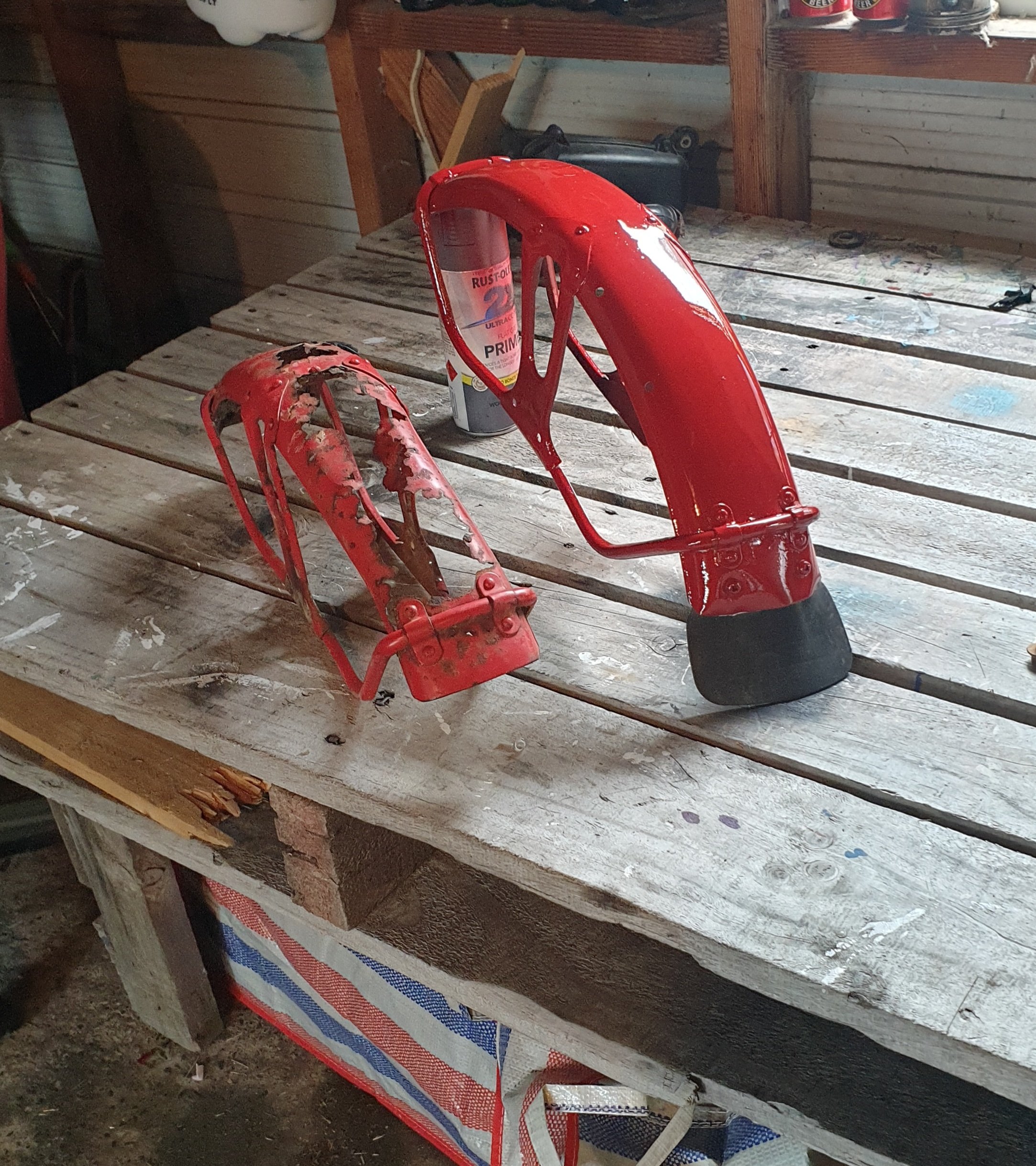
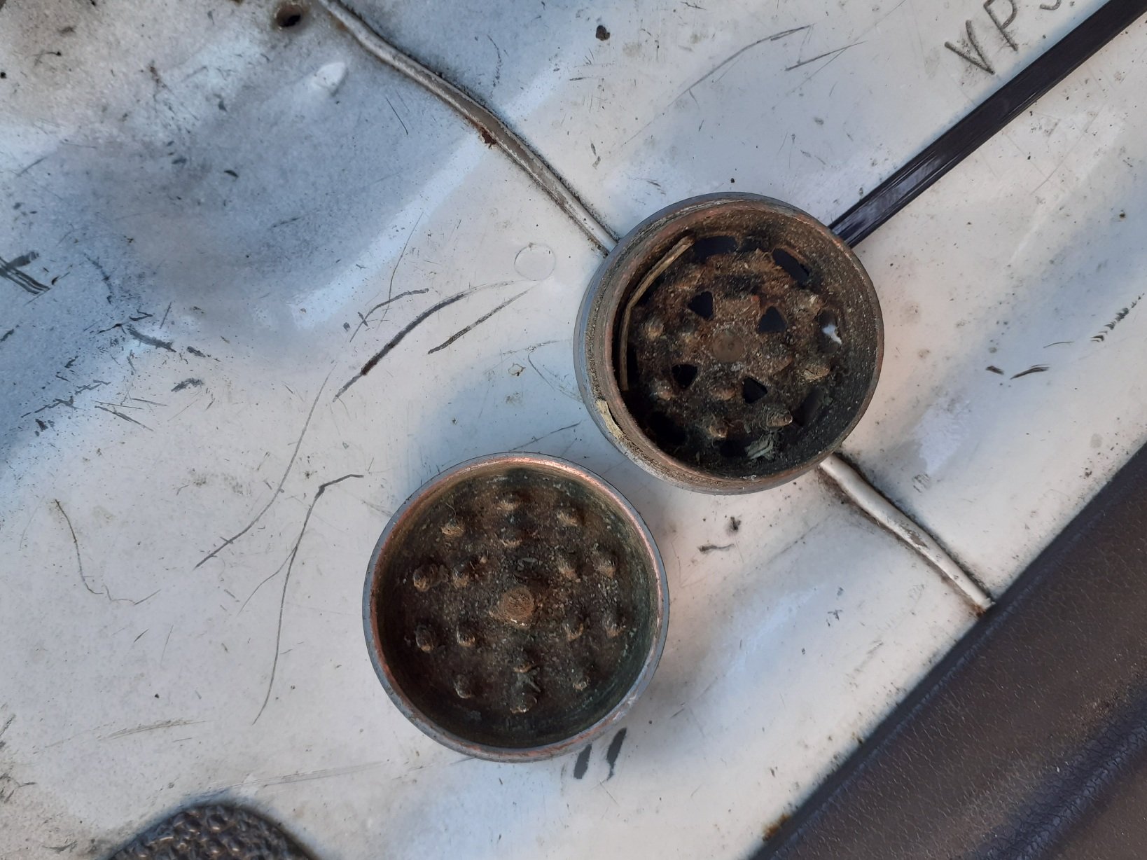
Lockdown gave me some motivation to do some quintessential 2 stroke maintenance. Everyone's favourite job - crank seals! This thing hasnt shown any signs of having fucked crank seals, but the motor was in unknown condition when i got it, and did show signs of hard starting and other giveaways. I had ordered a set in one of my previous yambits order cos i knew theyd need doing at some point. what better time than now ? Removal of old seals Pretty straight forward. Disassemble bike to get to engine side covers. remove side covers the right side required removal of the clutch and a few worm gears that operated the oil pump. this seal was easily accessible and you could remove it with a small pick. send new seal home with appropriately sized socket and job tidy. Left side bit easier to get to, you can see the old one was doing a bit of wees which indicated he was pretty tired. Replacement requires the removal of flywheel. then the points and magento behind it. This one required a trick out of Great Uncle Kenny's engineering handbook, by screwing a tecky into the old seal then pulling it out with a pair of pliers. New seal pressed in with a flat punch. This job then revealed more issues i need to remedy before i can put her back together; the kickstart oil seal is chooched. was doing mega wees on Te Ureweras (was hoping itd self-seal with a bit of Motu gravel tbh) and then pulling the clutch cover off truly reemed it. The points also look average and duller than a British weekend. so i will whack a new set in and hopefully unleash some more electrical horse power???? probably not This thing has a never ending to do list but at least the bits are available and easy to obtain. Will whack a yambits order in, along with a piston kit and away we go. Hoo Roo1 point
-
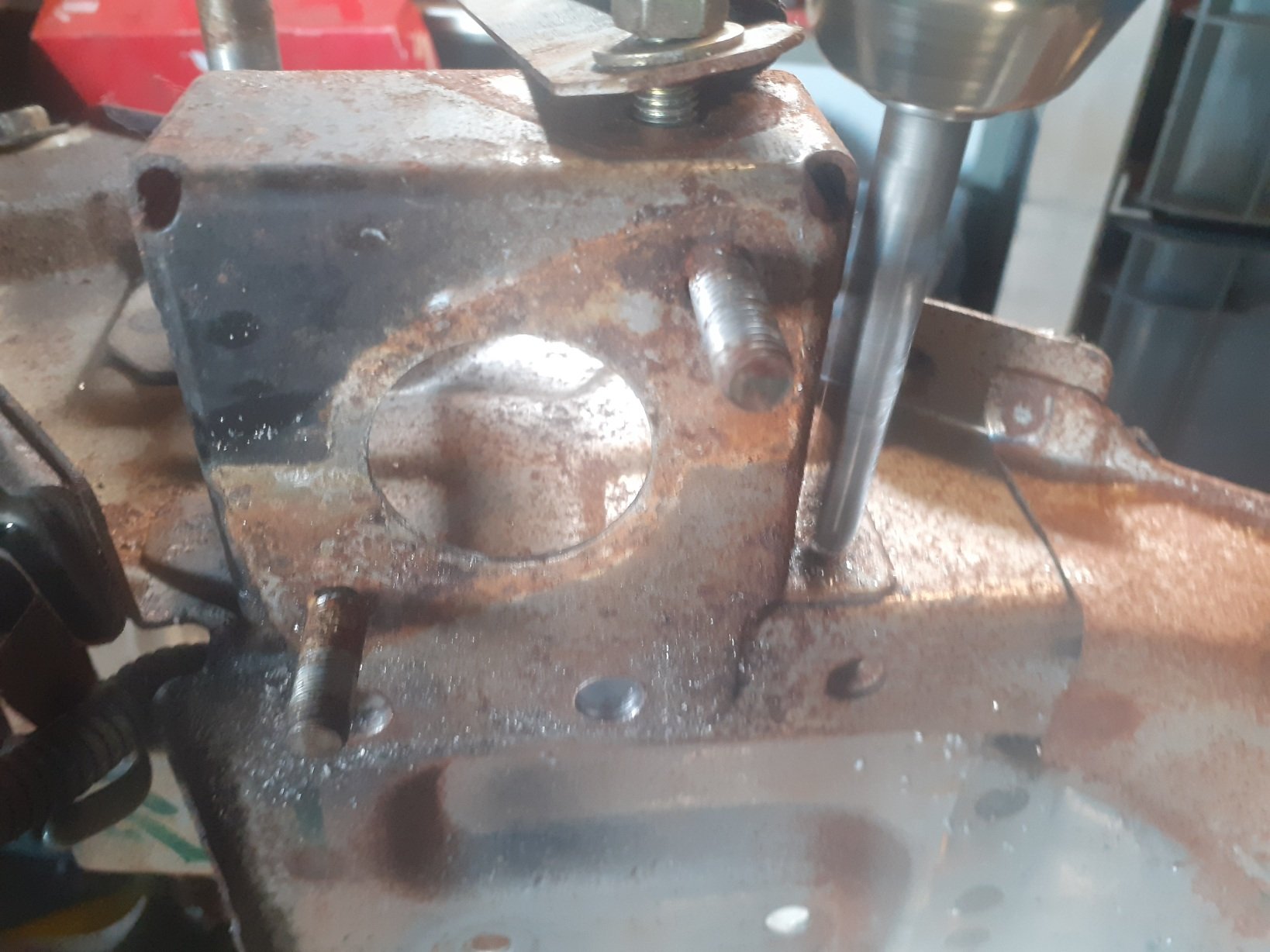
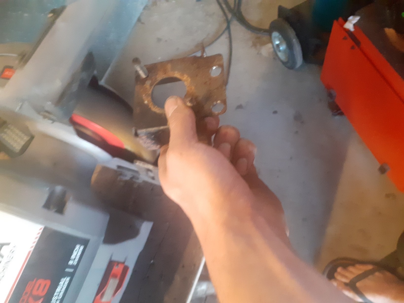
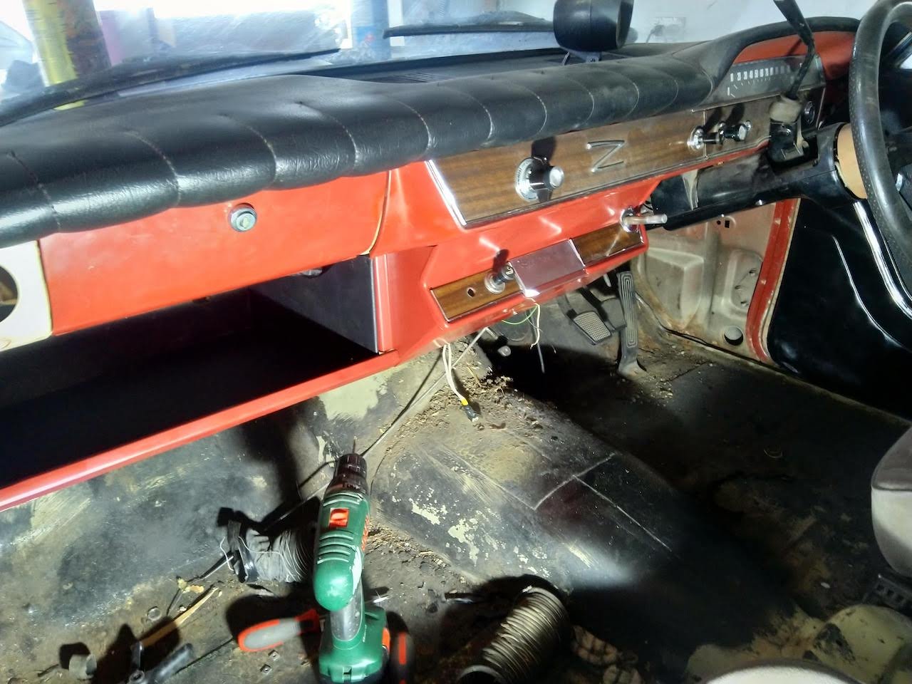
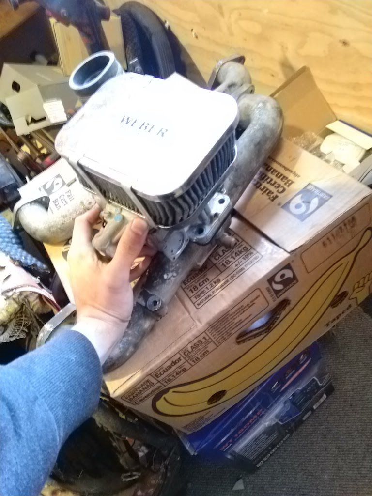
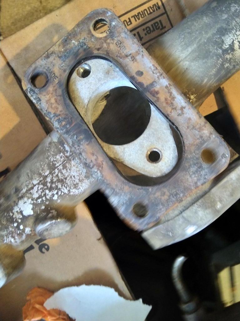
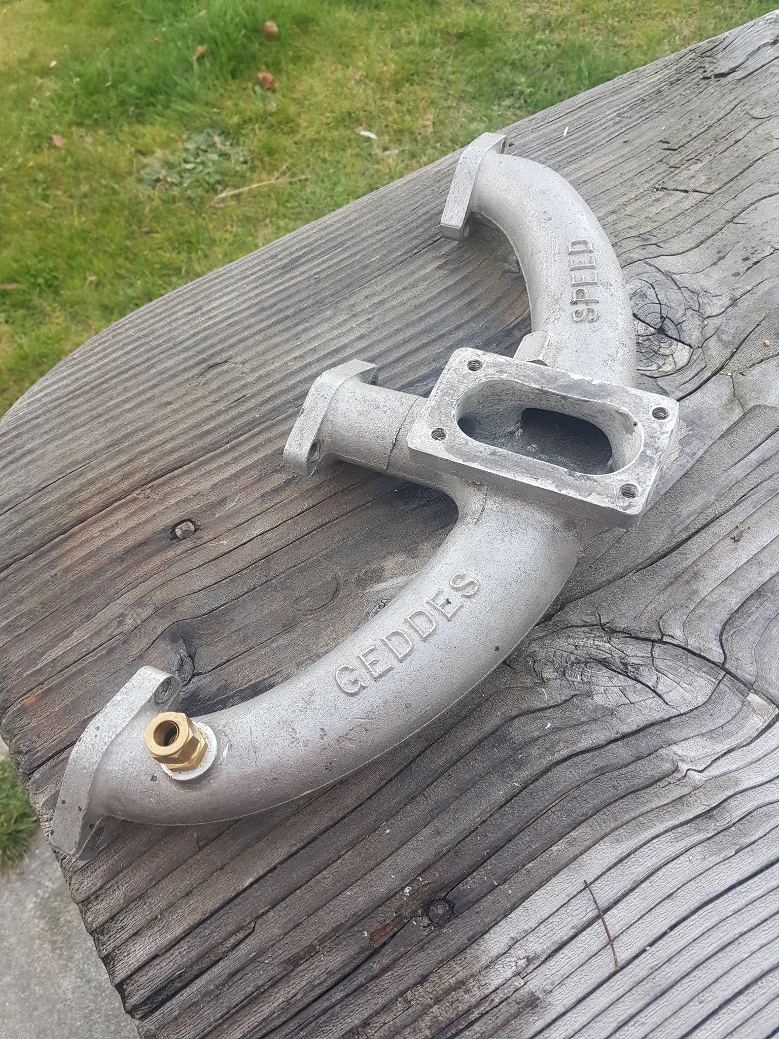
Got the dash all finished off, pretty happy with how it looks now. Got a colour matched rattle can and a can of matte clear. Looks fairly close to the original. Found someone on facebook who had adapted a factory manifold to suit a weber 32/36 carb, similar to a geddes speed one. I think I'll give it a crack, I've got a couple of spare manifolds so doesn't really matter if I screw one up. Plan is to cut off the raised mount, make a new carb flange out of 10-12mm Al plate, get that welded on then have a go at matching with a die grinder.
1 point


This leaderboard is set to Auckland/GMT+12:00