
Leaderboard


Popular Content
Showing content with the highest reputation on 12/23/20 in all areas
-
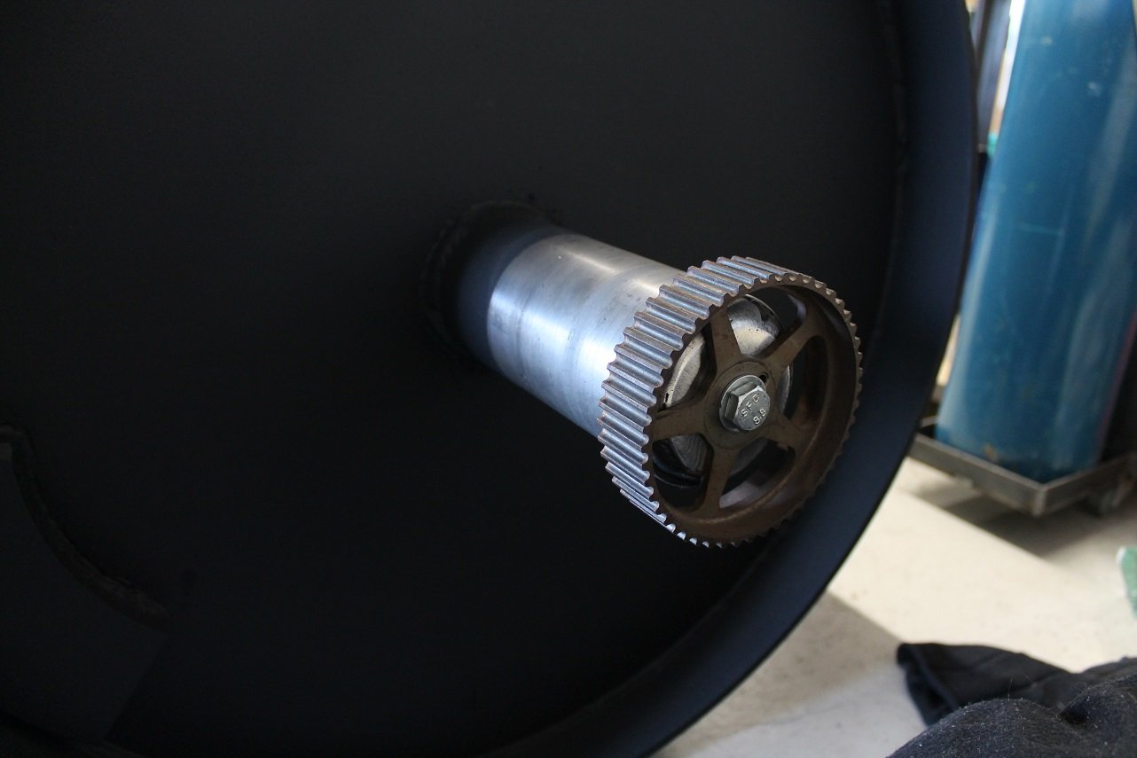
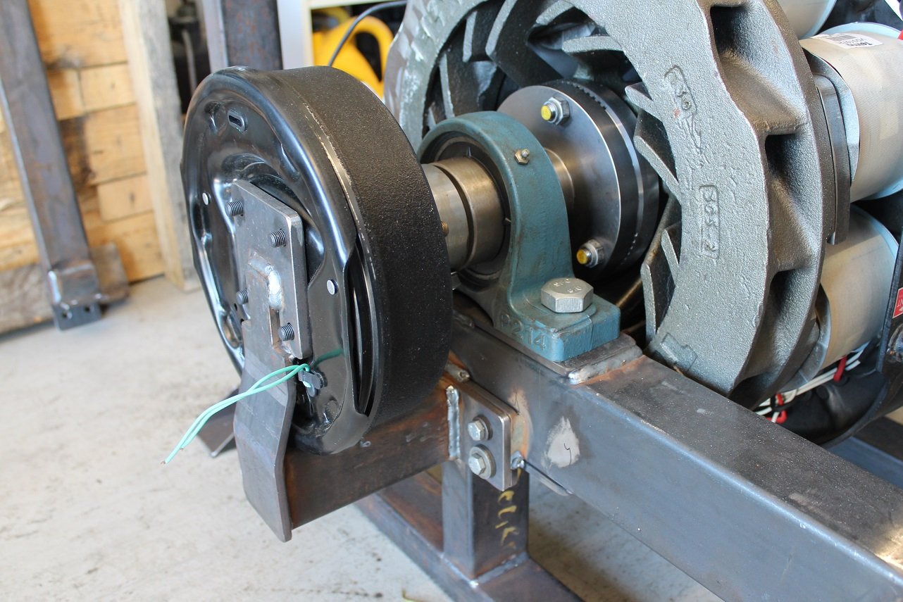
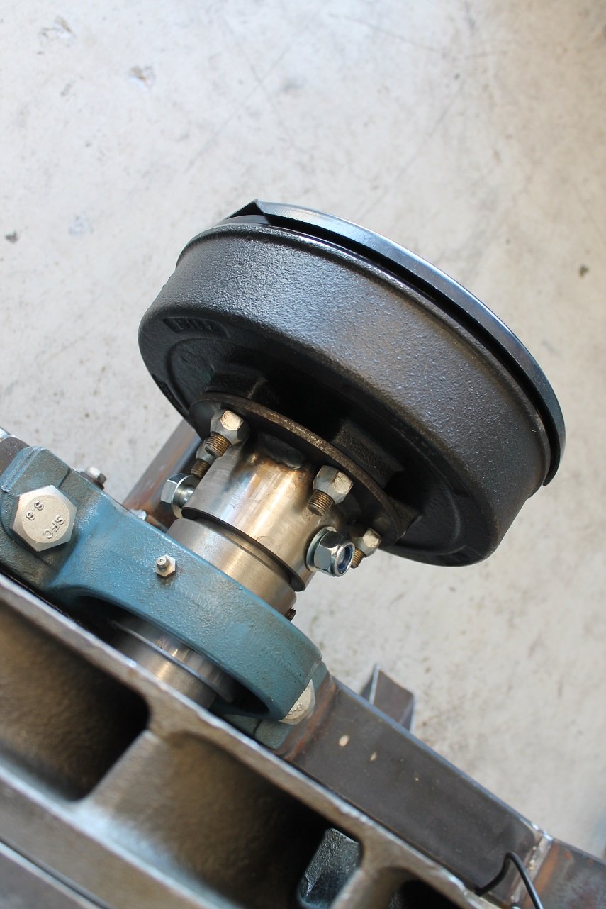
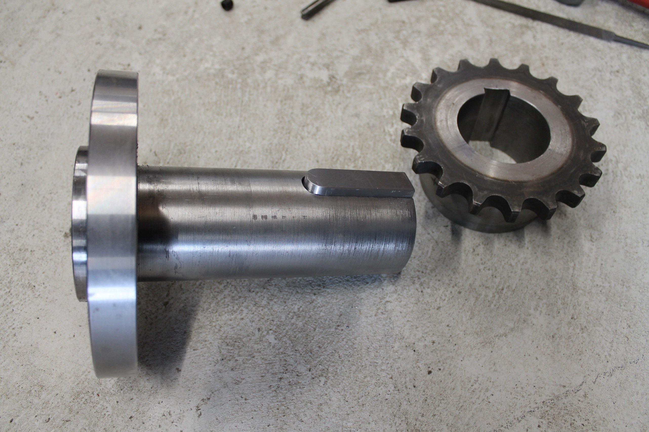
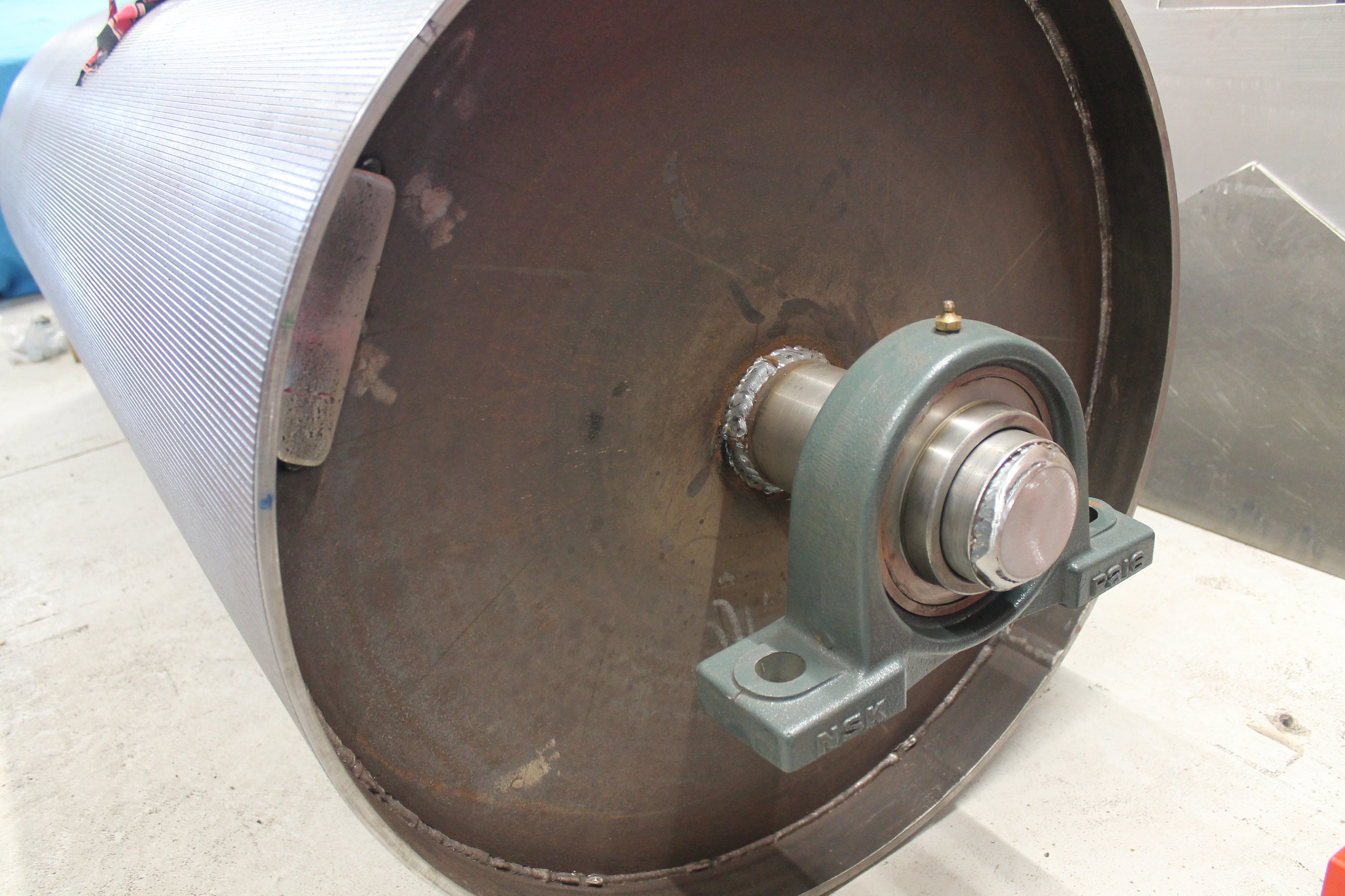
I then mounted a 2jz cam gear to the end of the roller, this will be used as a trigger wheel for the speed sensor. I then set to rewiring the Telma retarder. These have 16 coils wired in parallel for a 24v system on a truck - this is no good for a dyno. I wired the coils into series so it now runs on 192v, which can be wired to mains power through a power supply. With the retarder wired to a 12v car battery, the coils can be checked with a compass to make sure the wiring is correct. They should read north - south - north - south around the circle to form the eddy currents, which are transferred into the rotors to apply braking.
 21 points
 -
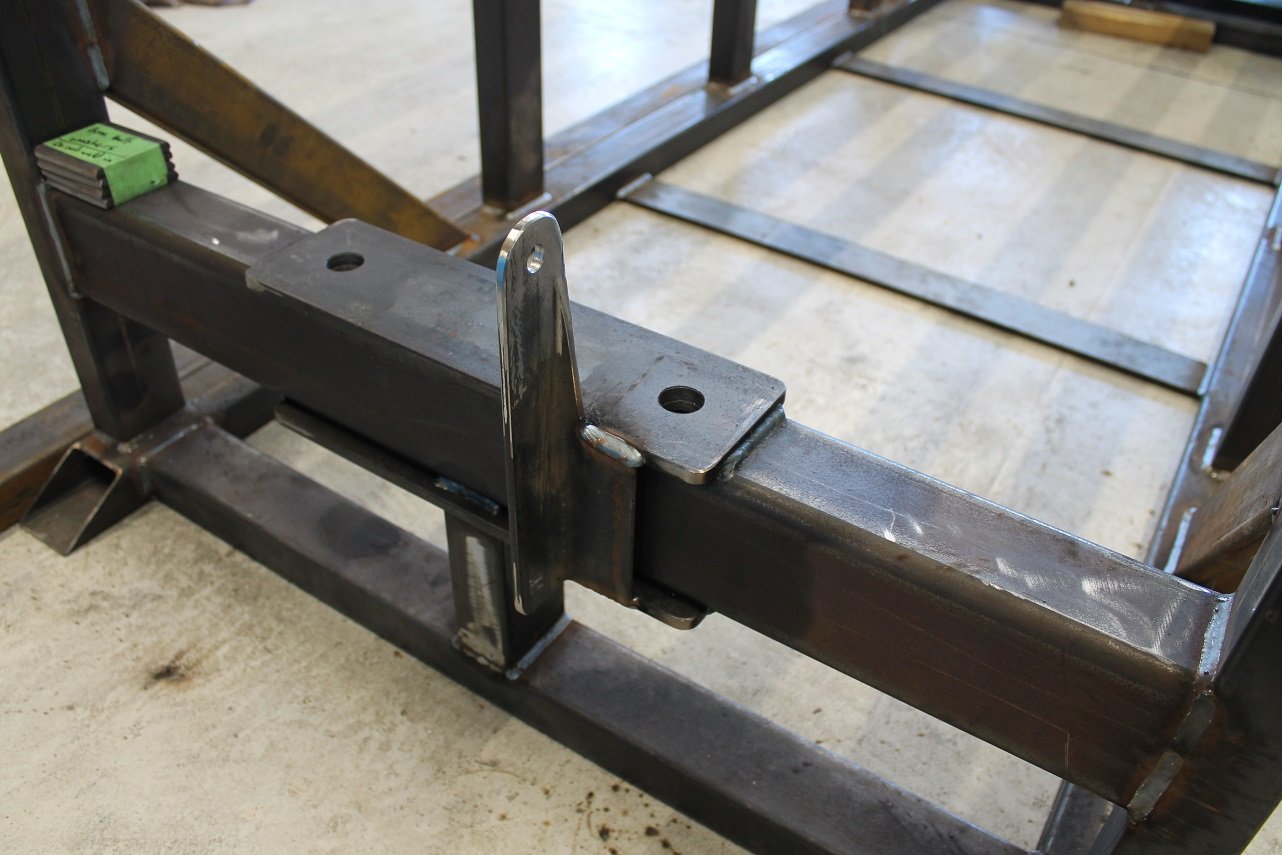
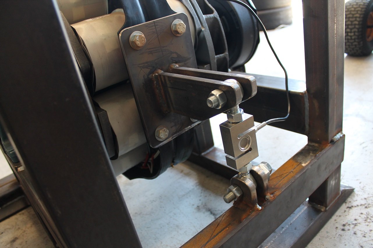
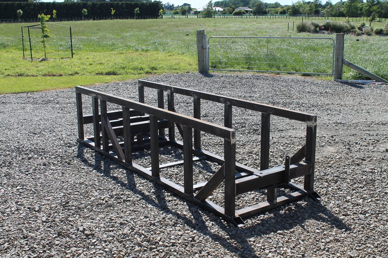
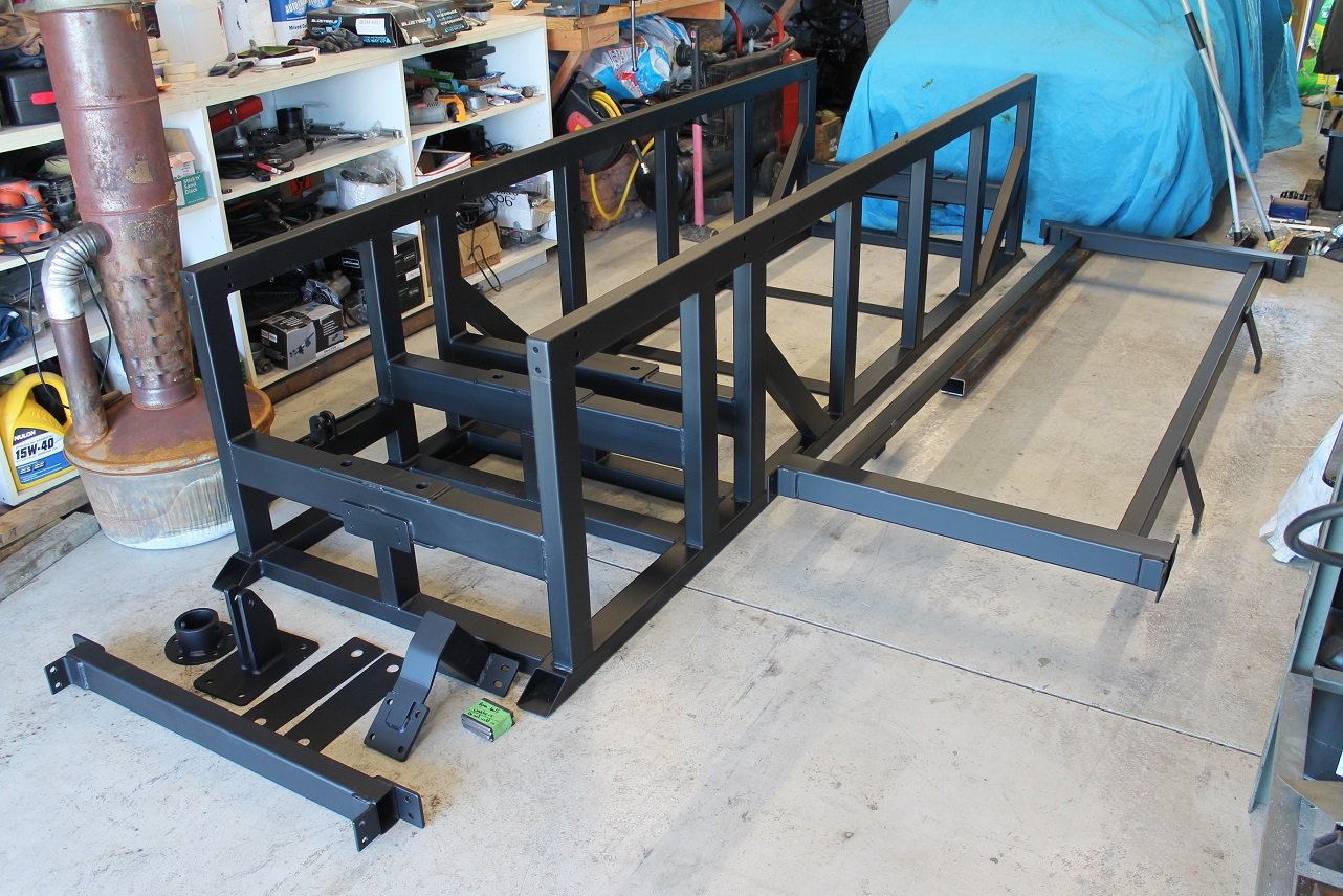
While I waited a few weeks for the concrete, I built a frame for the dyno. Speed sensor bracket Load cell bracket. This is what measures the torque. Electric drum brake to lock the roller when mounting a car. Frame painted. The part sitting next to it bolts into the top to support the floor coverings (steel checker plate)
16 points
-
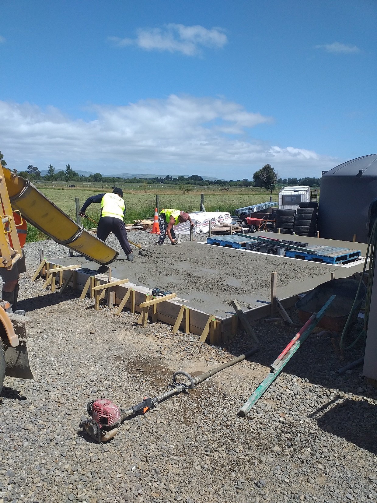
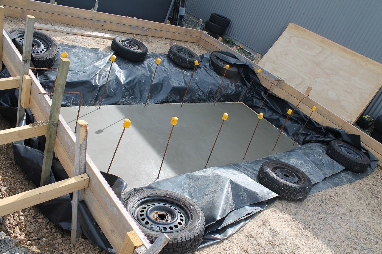
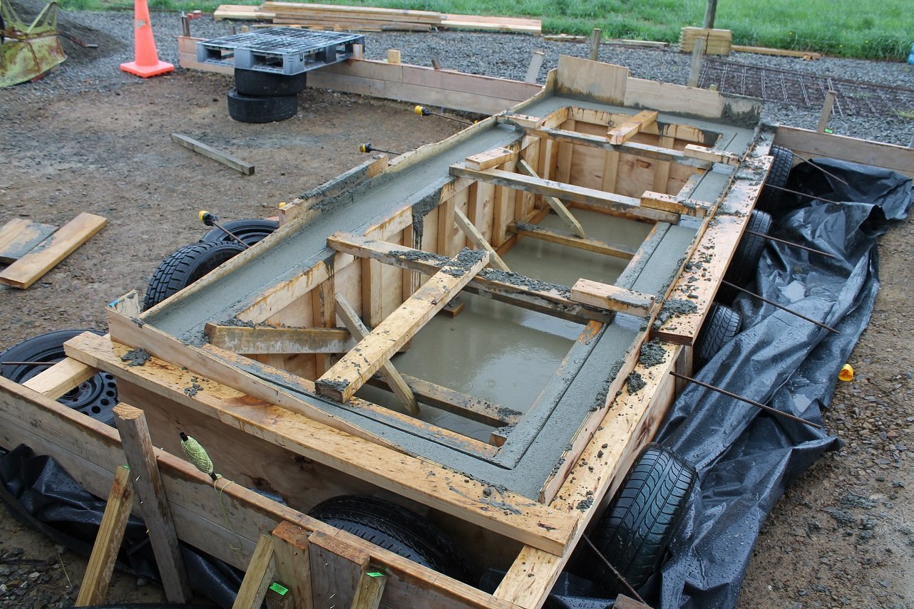
Other concrete truck companies were booked out until 2021 so I couldn't even get the concrete to attempt it myself. Early December I started begging the concrete company boss. I told him all I needed was the concrete truck, a man with a screed and a bull float and I'll finish it myself by hand. Hoping this would persuade him as I'd only need an hour of his placer's time. December 14th. I rang him to ask if we were still on for that day. "Yeah but it'll be late in the day" - My hopes were low by this point as other jobs could have dragged on and it be too late in the day to do mine. But finally they came, and were gone in less than an hour. I spent the rest of the evening doing the door rebate, steel floating the slab by hand and drinking beer. I'm no concreter but it came out alright.
16 points
-
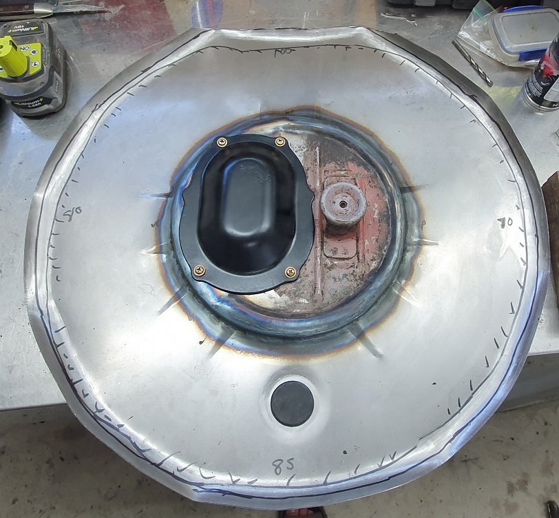
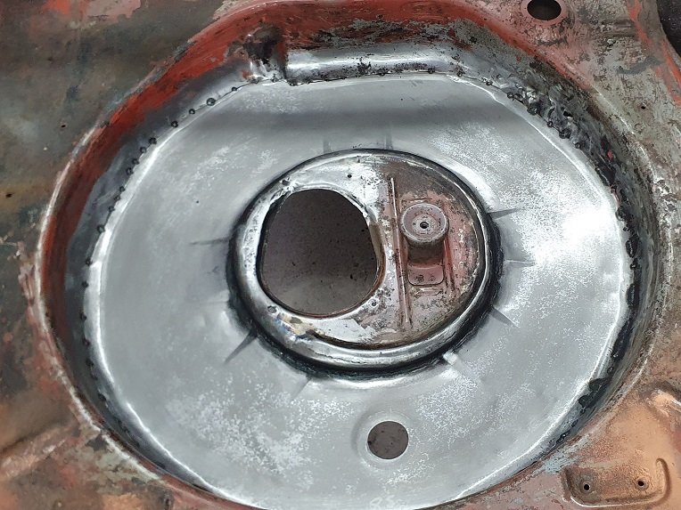
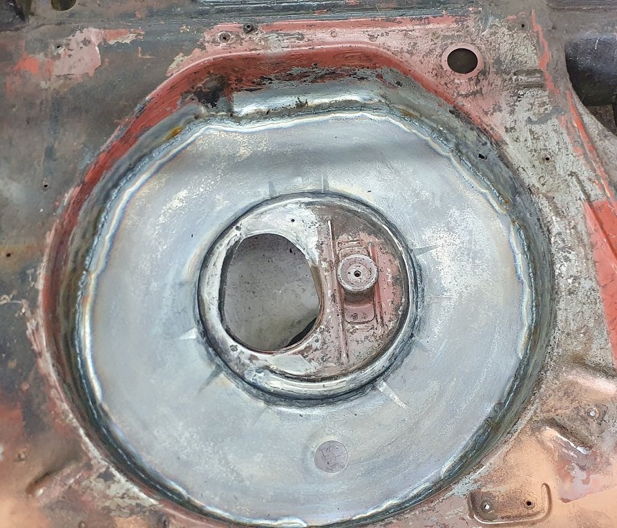
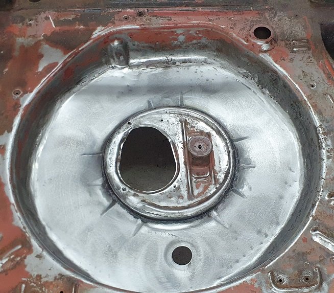
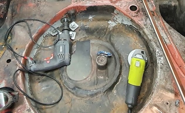
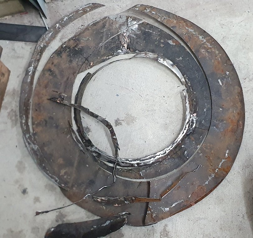
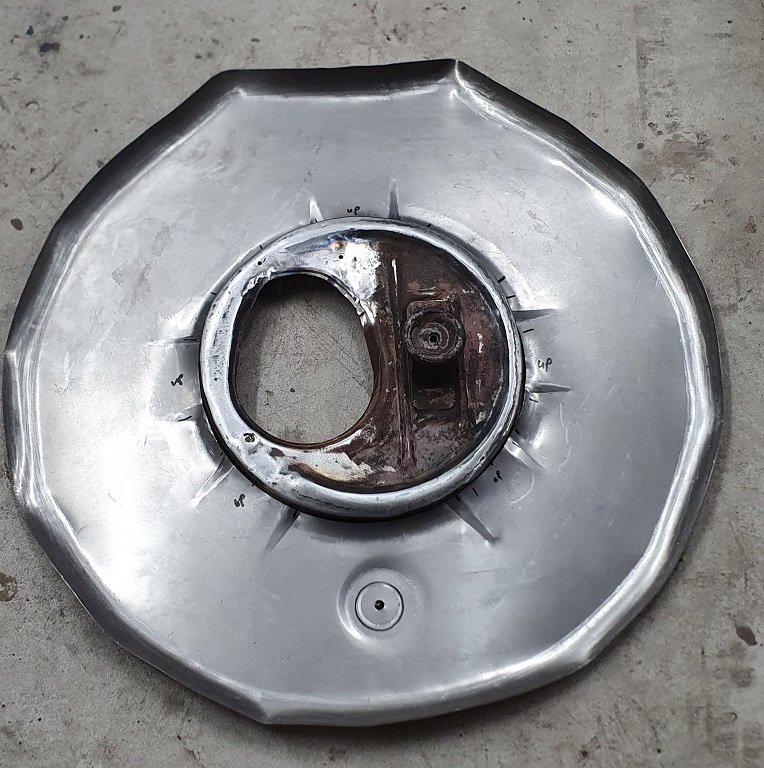
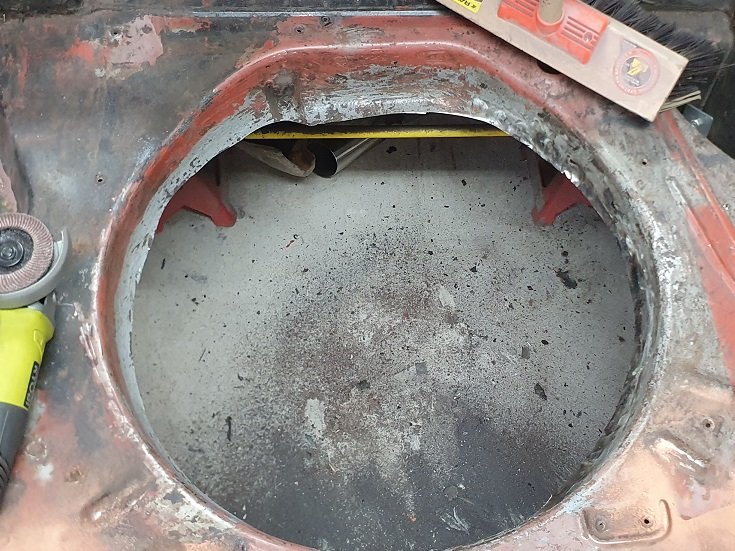
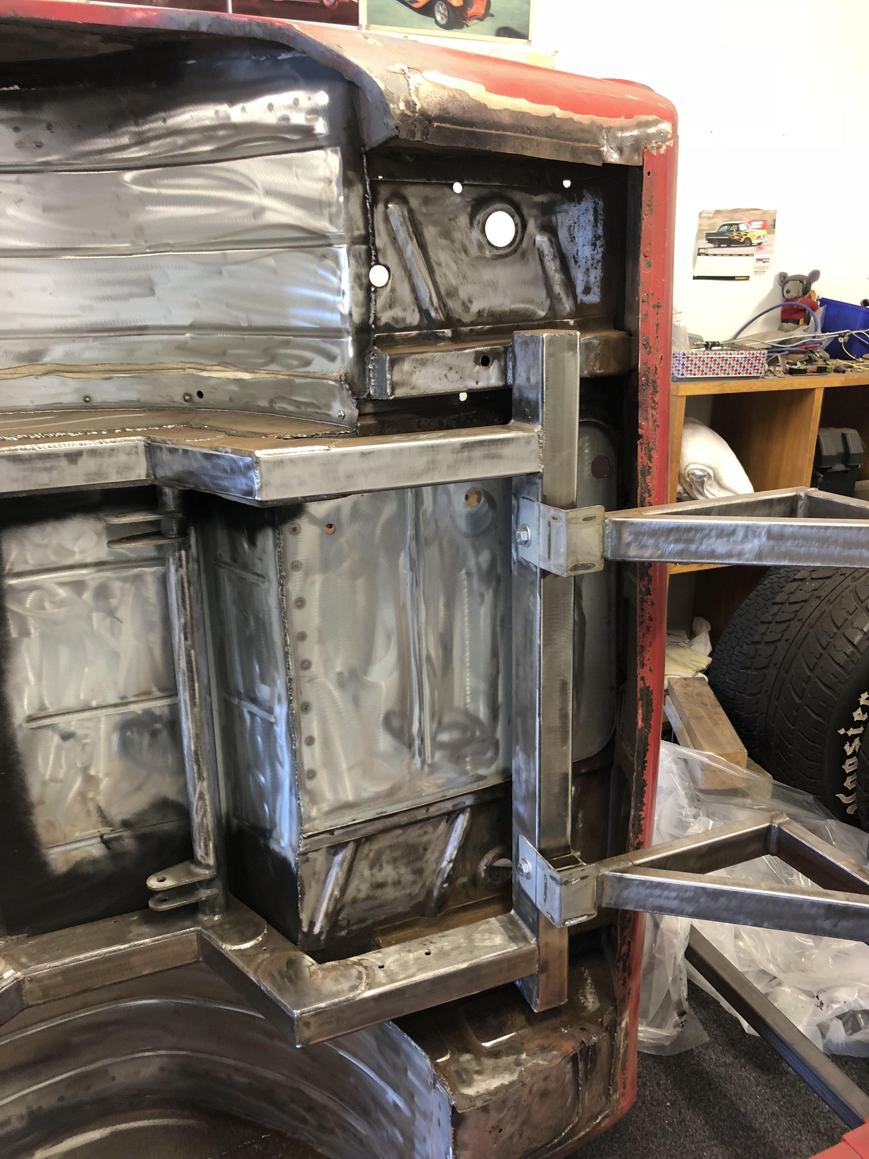
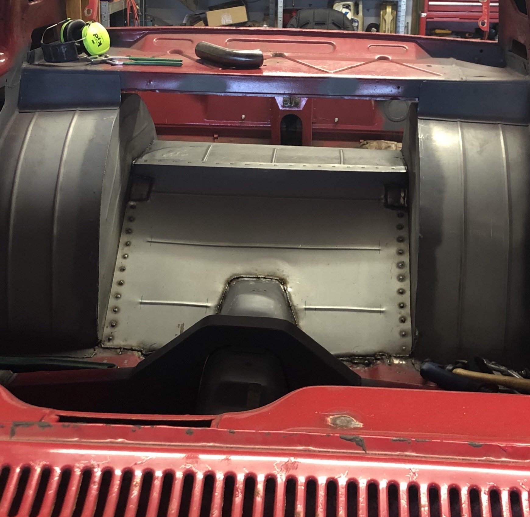
Spare wheel well! been a while in the making. It was looking like a sara lee danish dessert in there - layer upon layer upon layer upon layer... and bits chopped out etc etc. so choppy choppy Fixed up the middle part to look somewhat right and cut/pressed the stiffening and drain into a new bit. rolled the edges too welded the centre in and tested the cover Tacked in. welded and sanded Pretty happy with the result - way better than before.
16 points
-
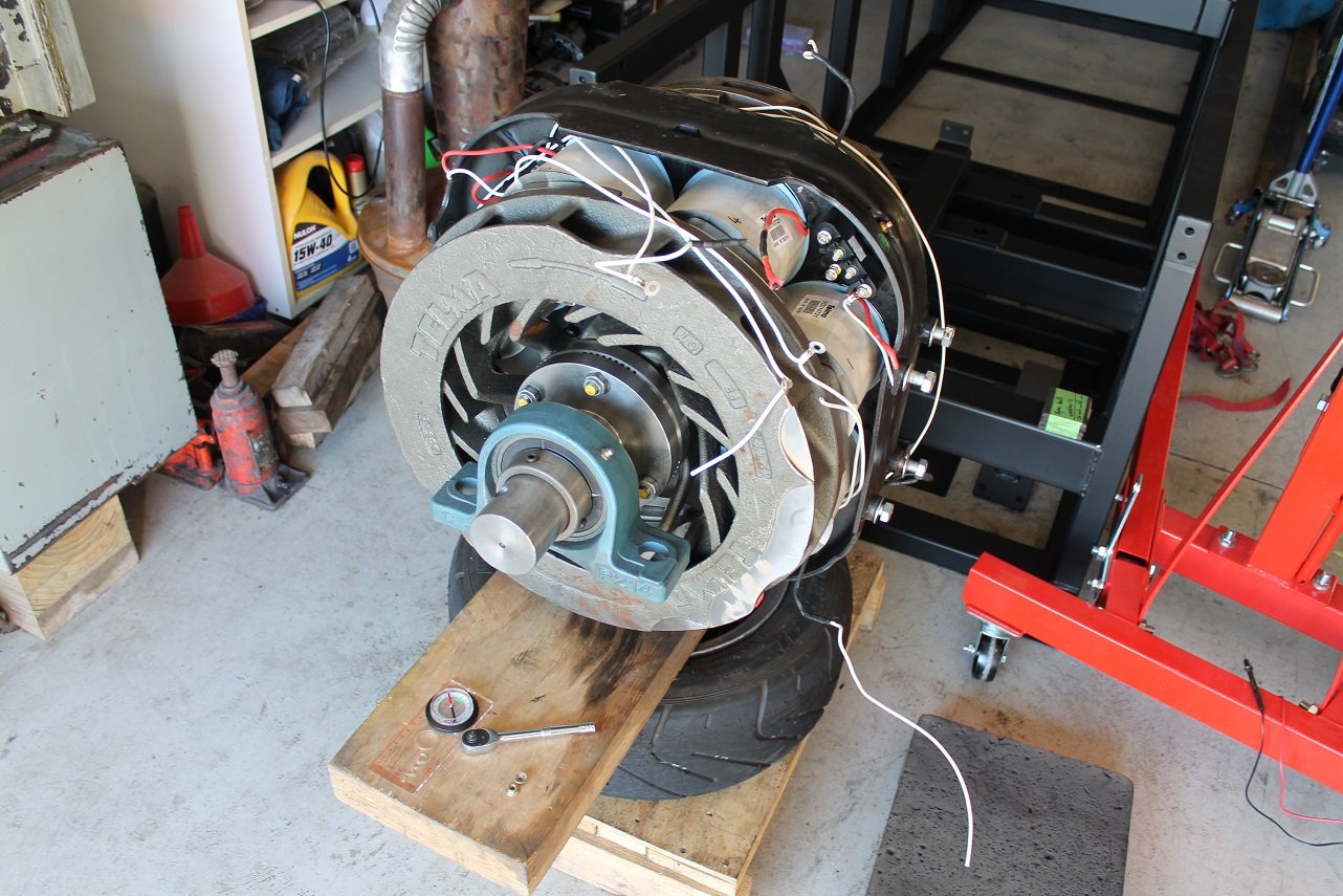
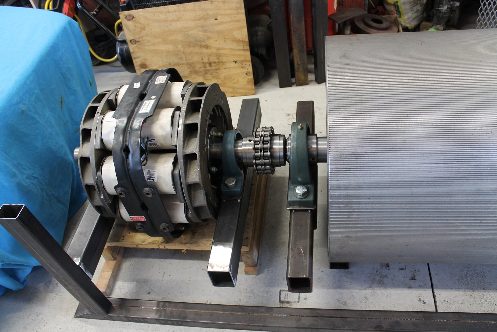
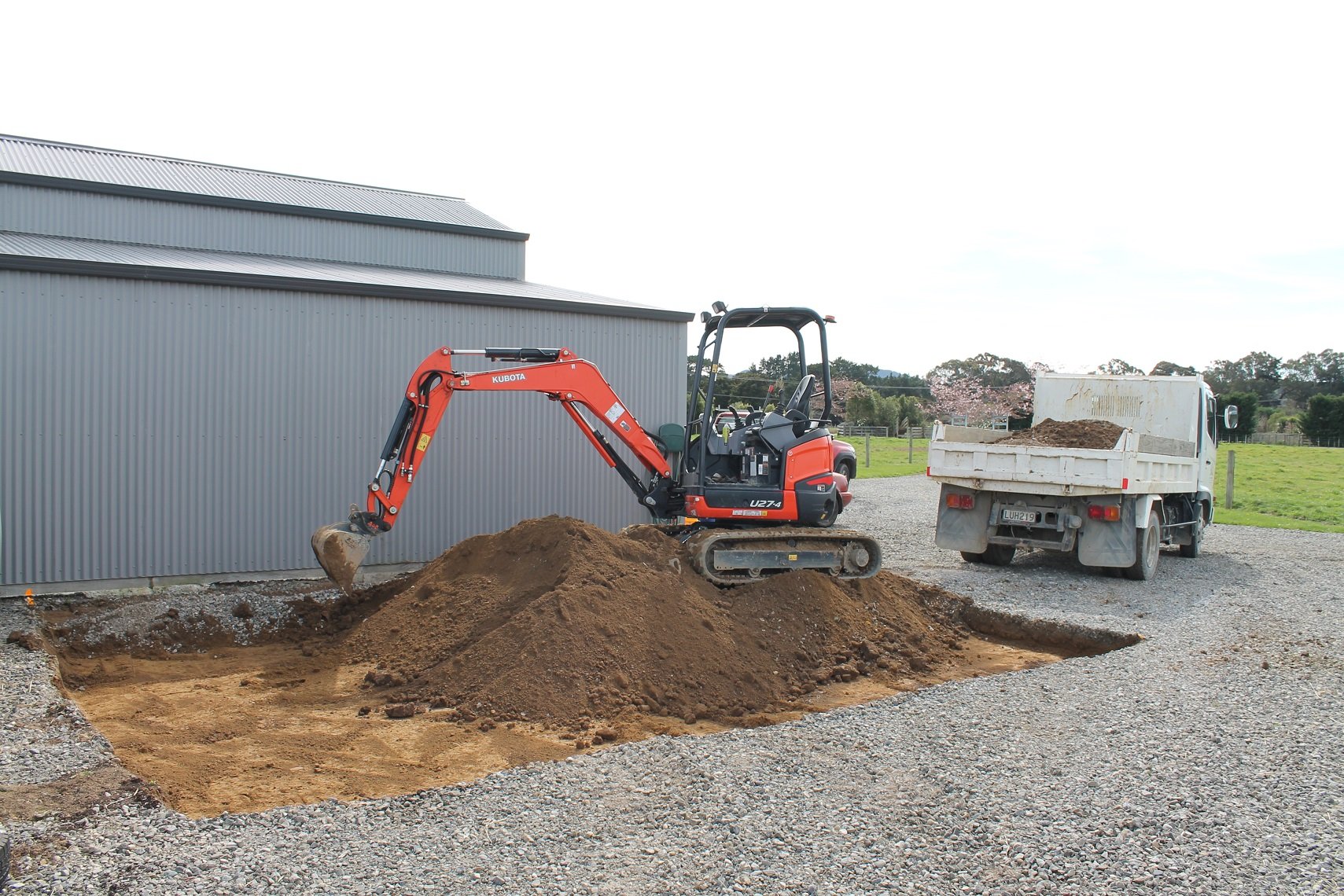
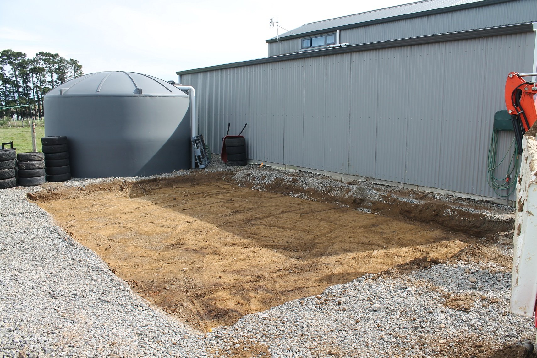
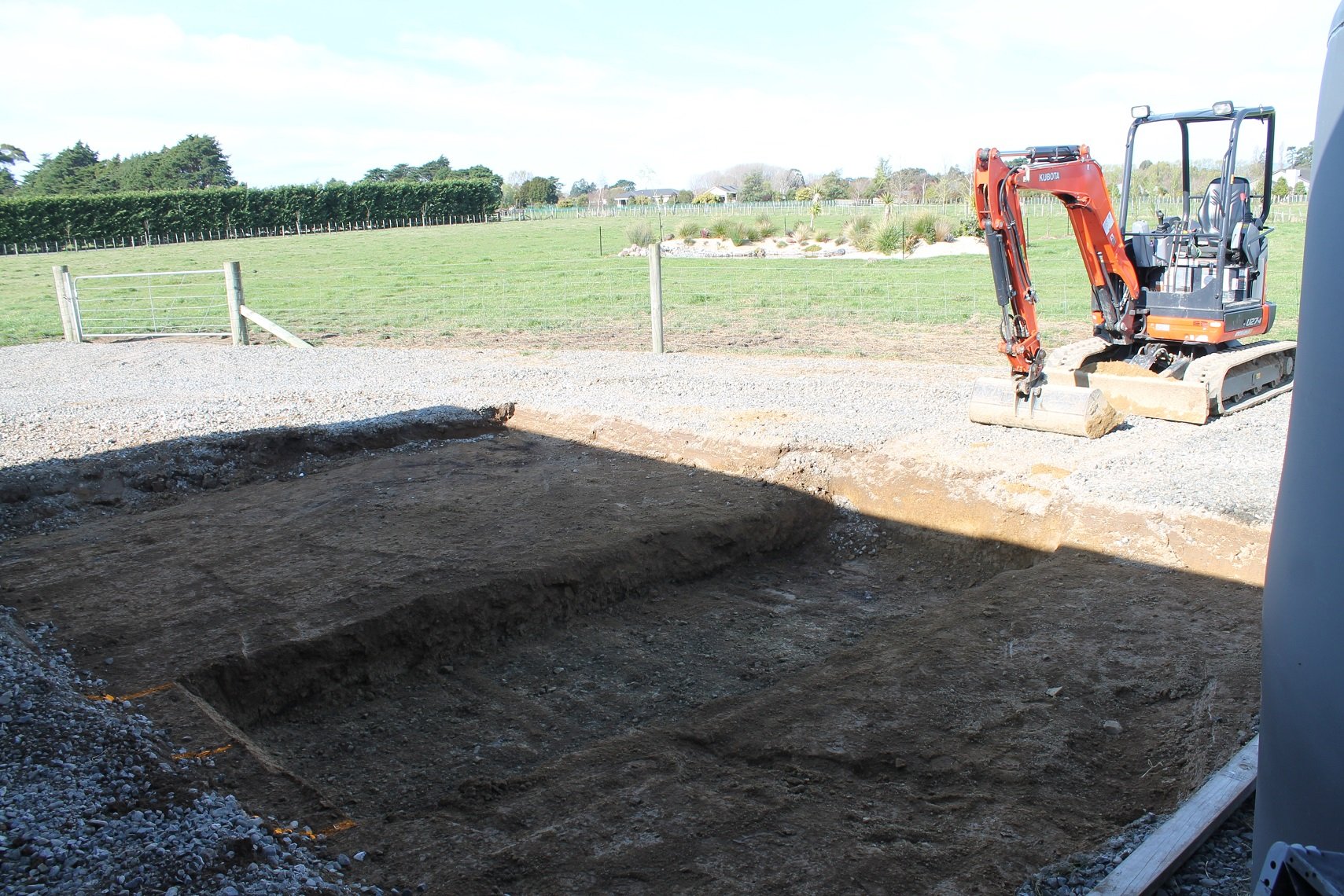
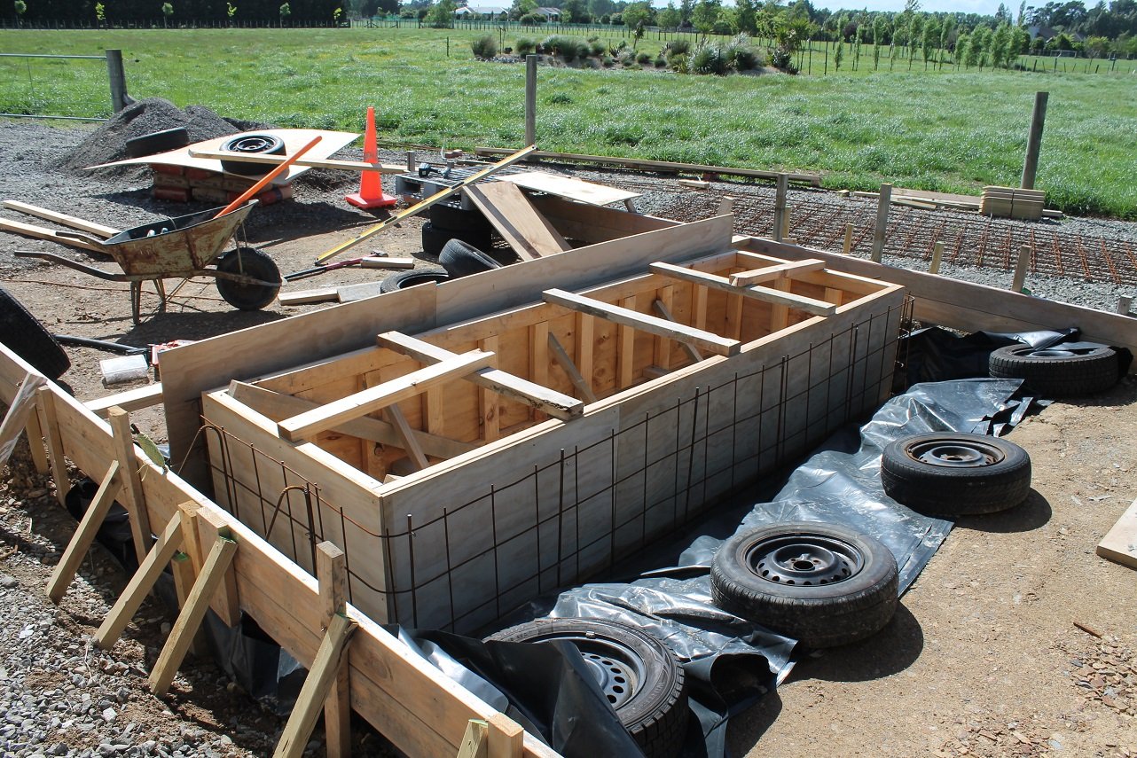
Catching up on progress now, this update is from 3 months ago. With the chain coupling finished, I could finally mate the roller to the retarder and get an idea of the frame dimensions. Which I needed to know so I could build a pit for it to sit in. I have no room in the current workshop/house, so I'd have to build another shed, as a dedicated dyno cell. I decided to drop a day from work each week to try and get something built before the Christmas holidays. So I borrowed the digger from work and got to it.
14 points
-
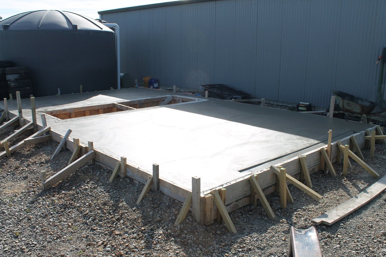
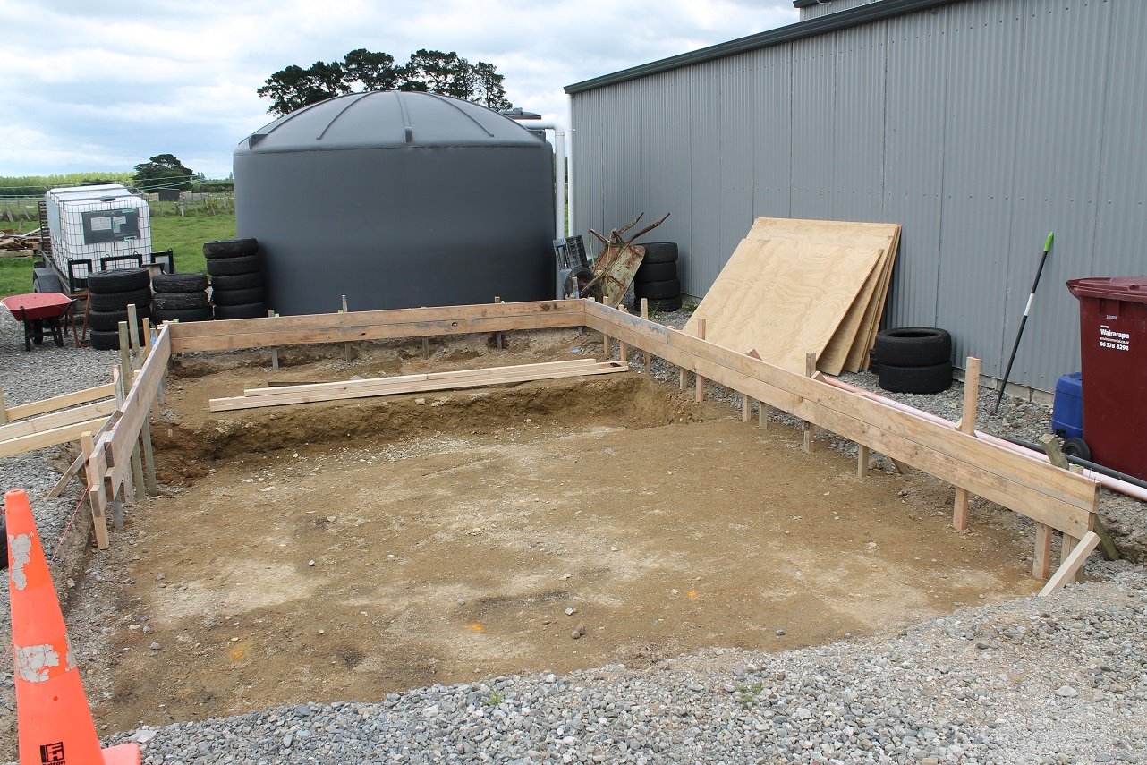
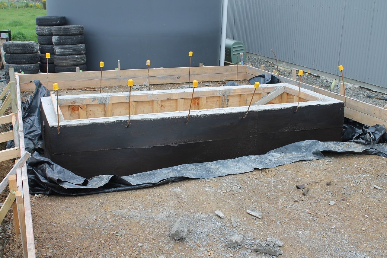
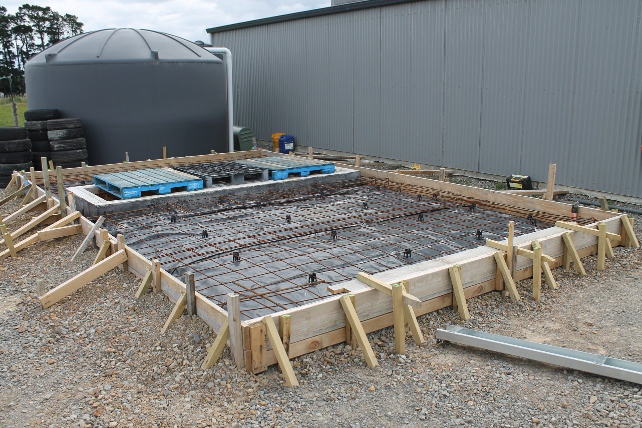
Dyno pad poured Pit walls boxed and poured. They bowed a bit more than expected on the outside, but a little bit of extra concrete never hurt.. Except for my back due to doing it all by hand with a mixer. Molesealed the outside and used 3 layers of polythene underneath and up the walls to stop water getting in (water table gets quite high here) Finished the prep ready for concrete. The last photo was on November 26th. I let the concrete company know 6 weeks prior that it would be ready at the end of November as I know they are extremely busy, and kept mentioning it to them so they knew where I was at. Getting stressed about it not happening as December was rolling on and the Christmas rush was in full effect for the building trade. Not only that, it kept raining when we planned to pour!
12 points
-
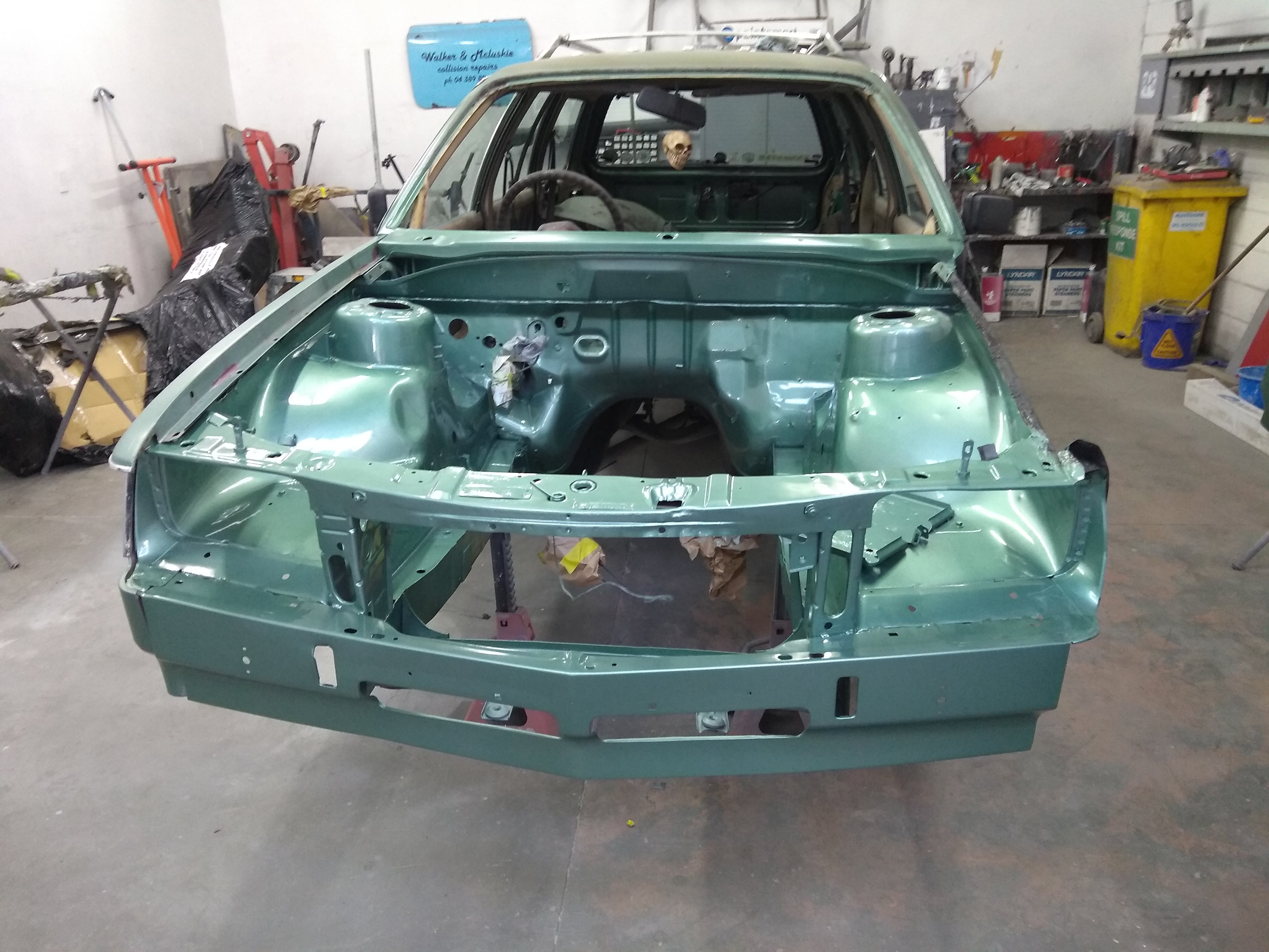
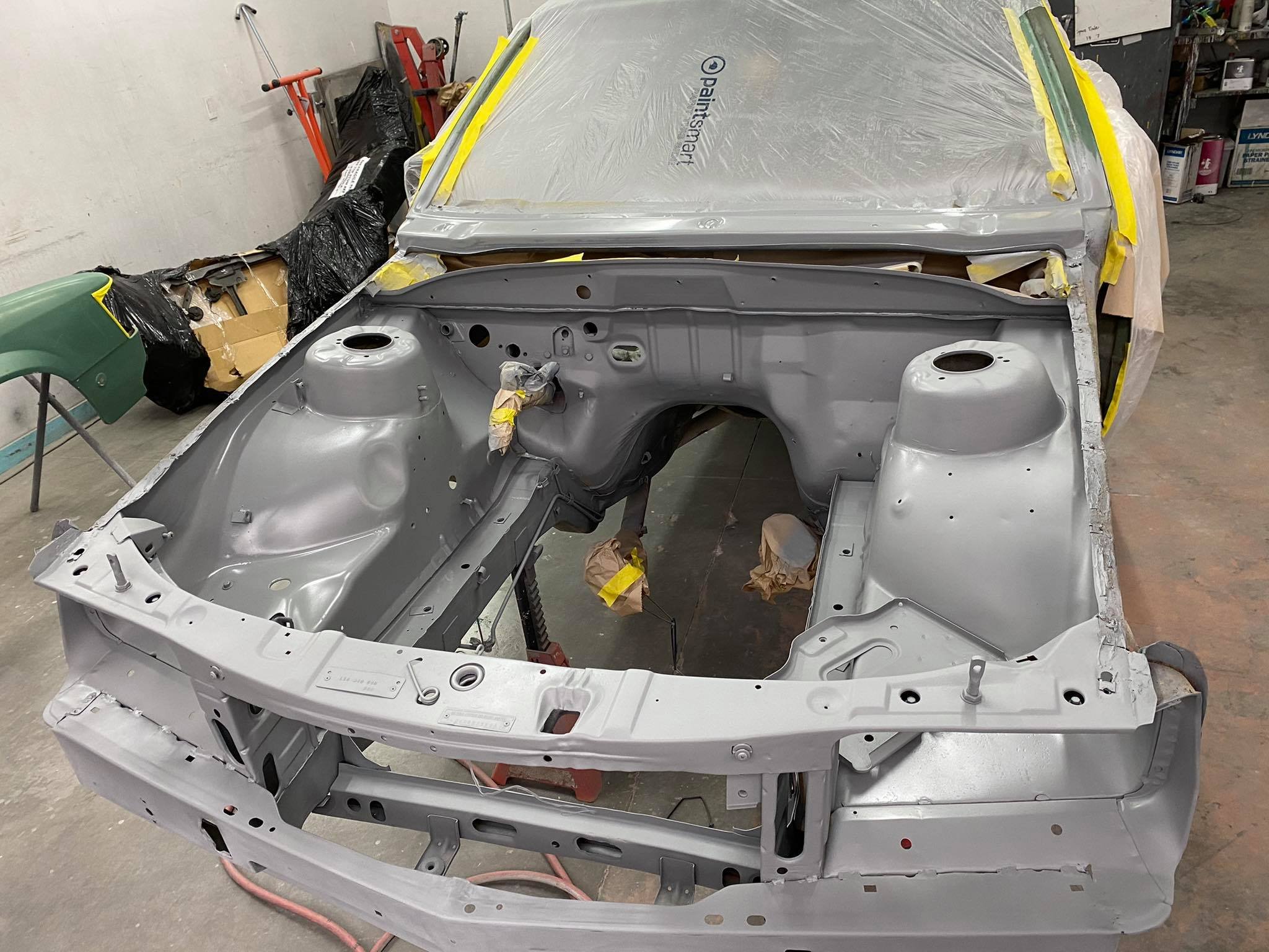
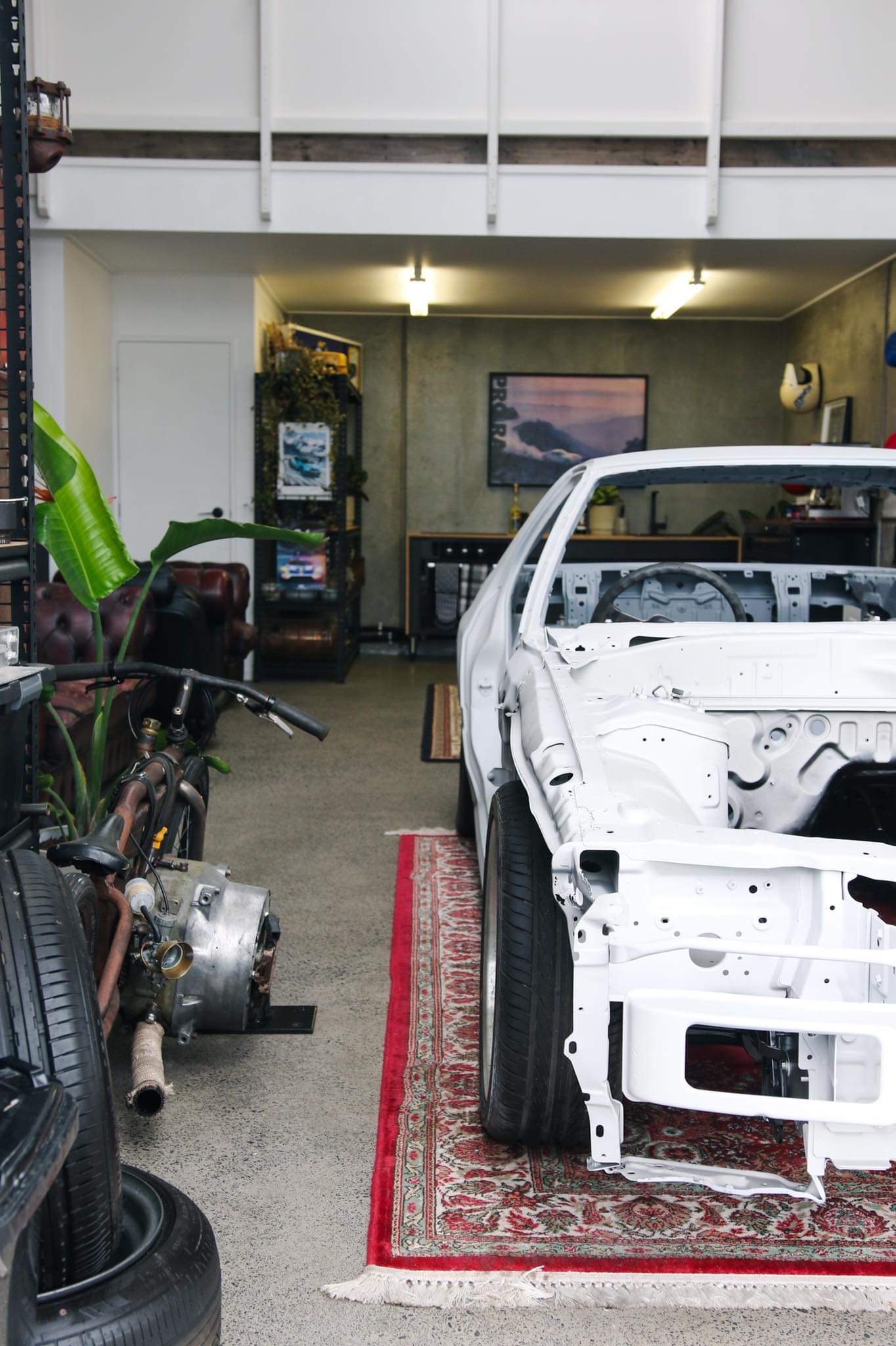
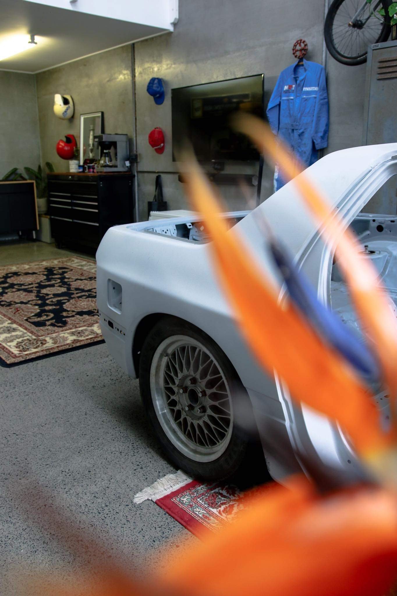
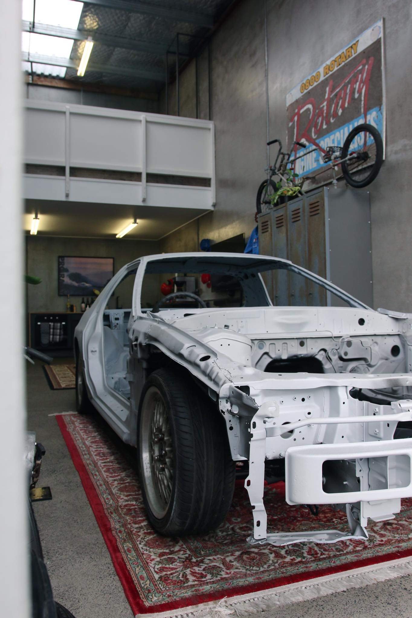
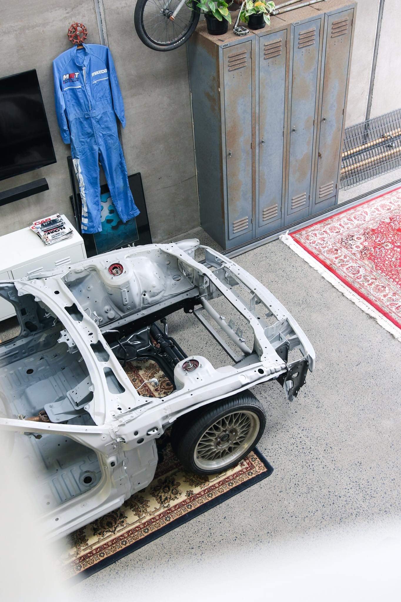
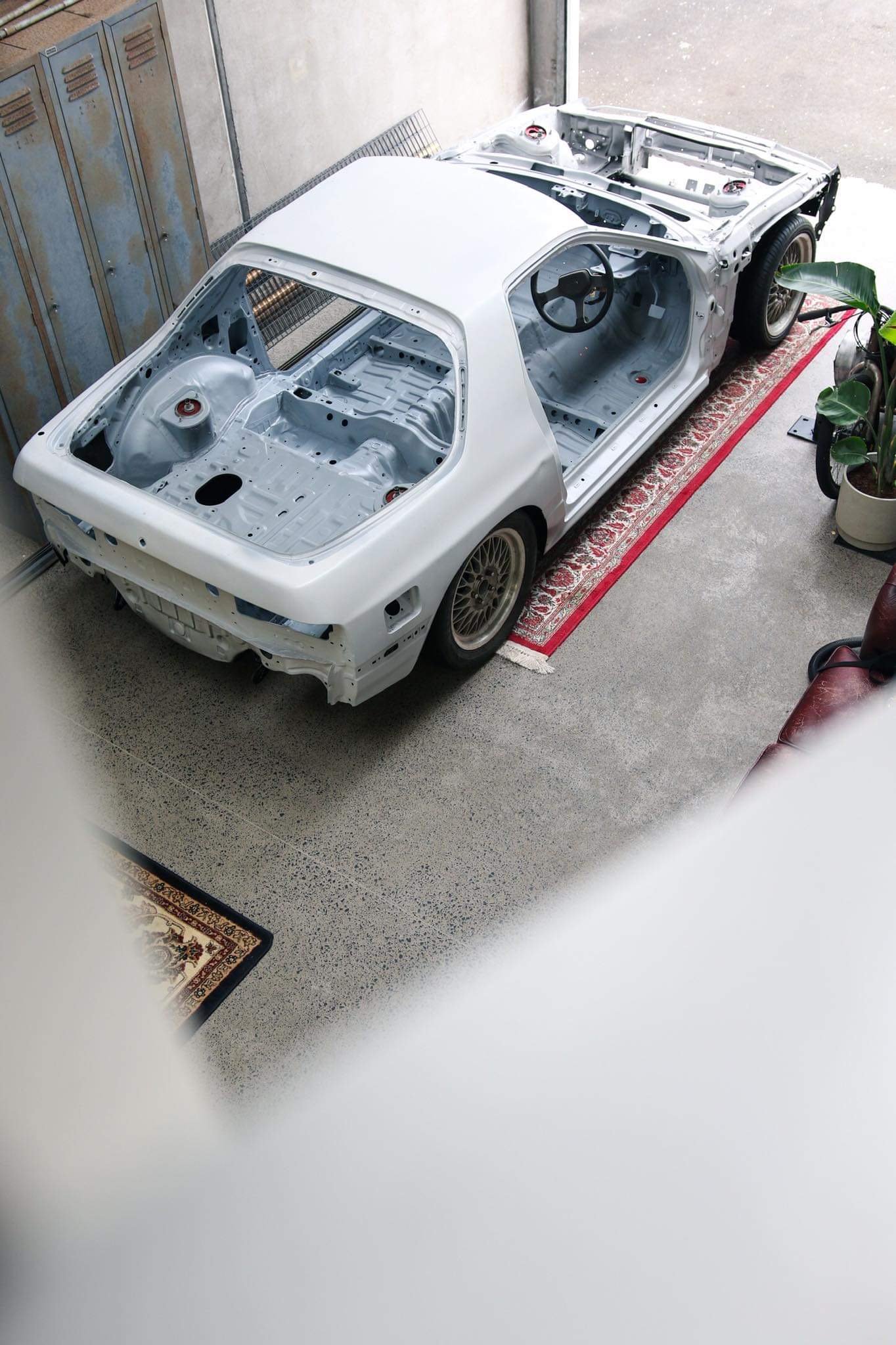
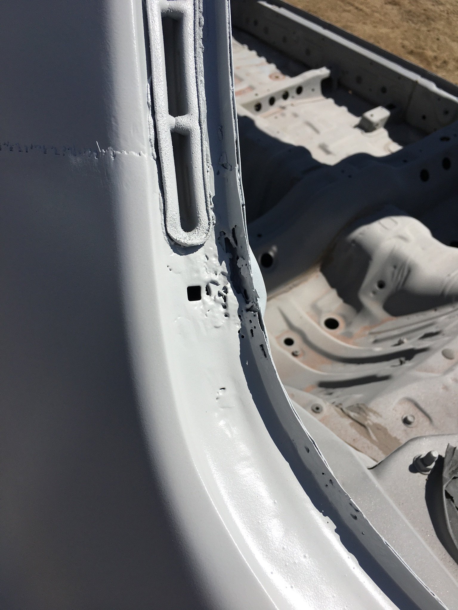
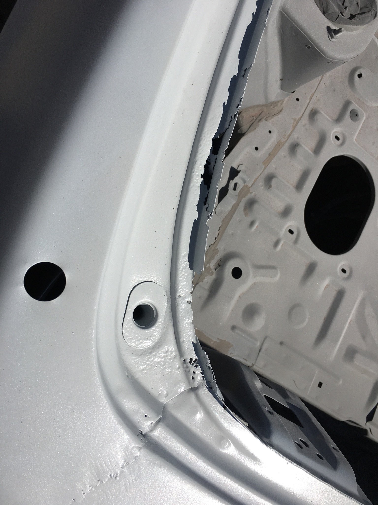
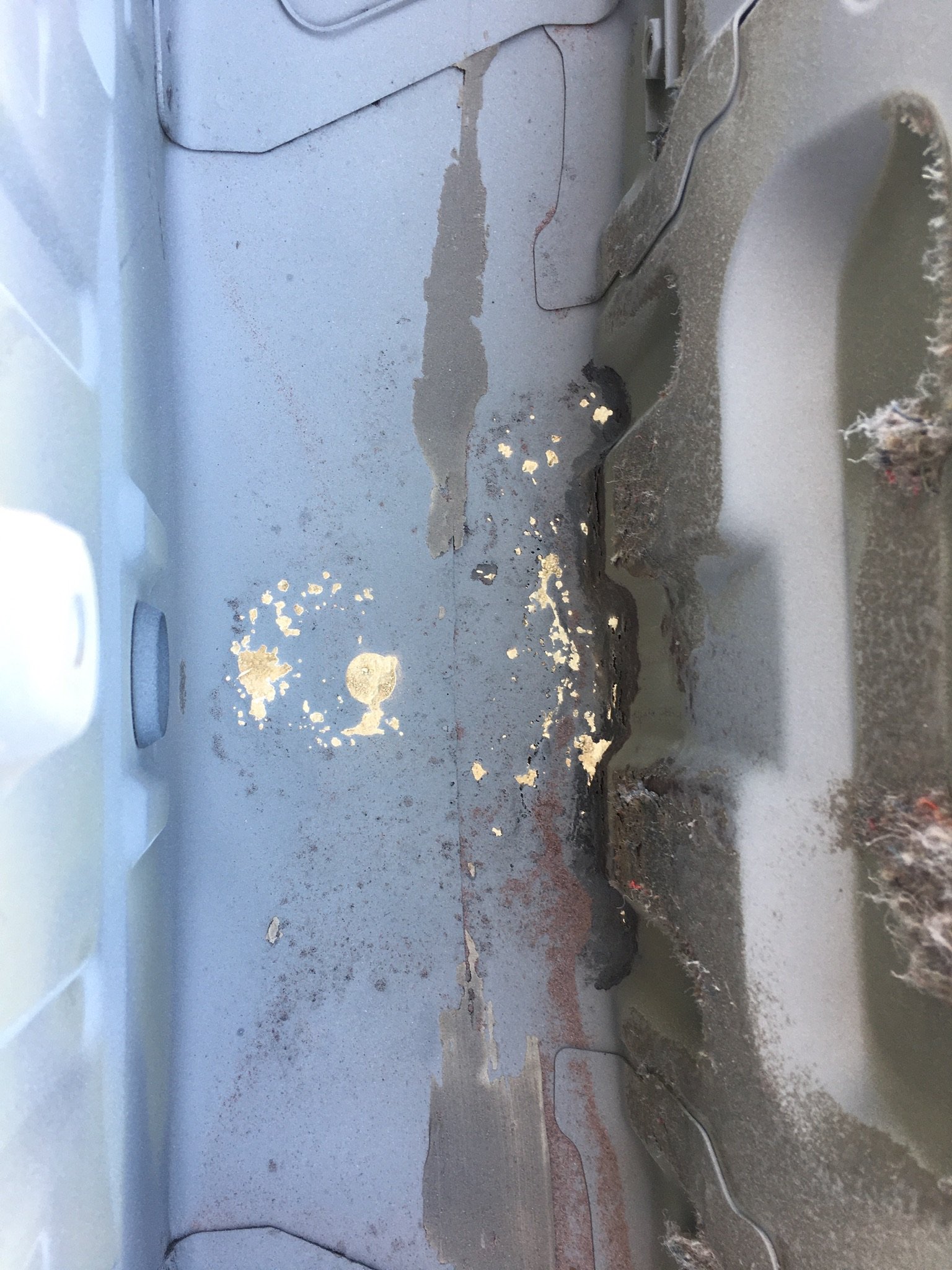
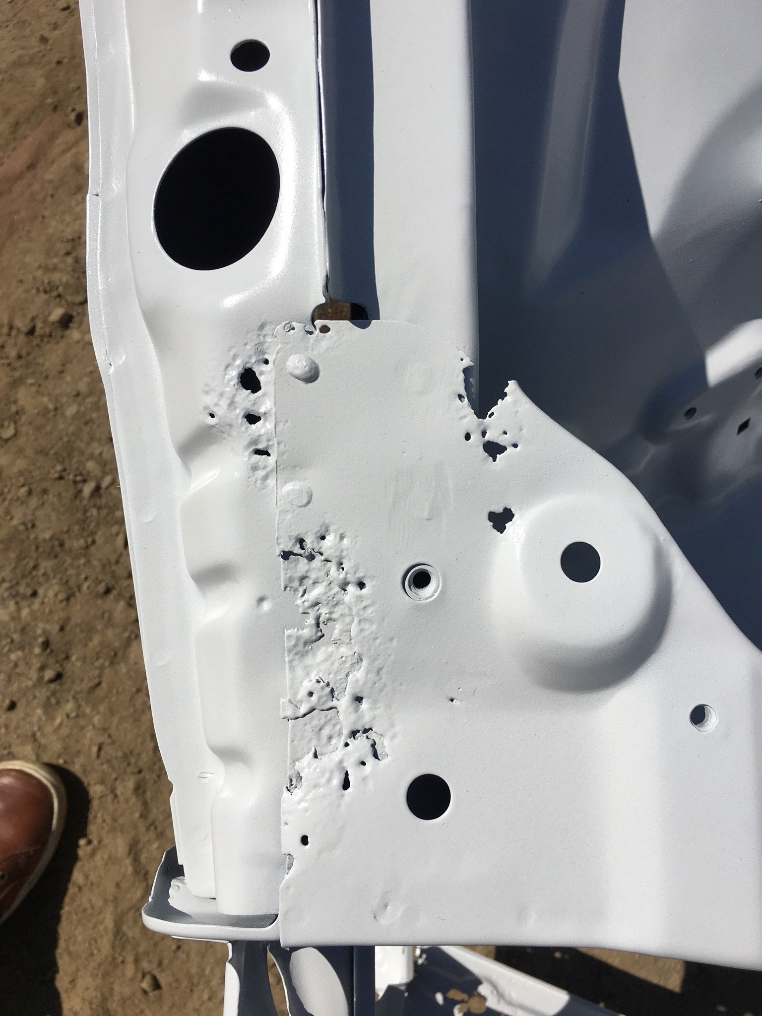
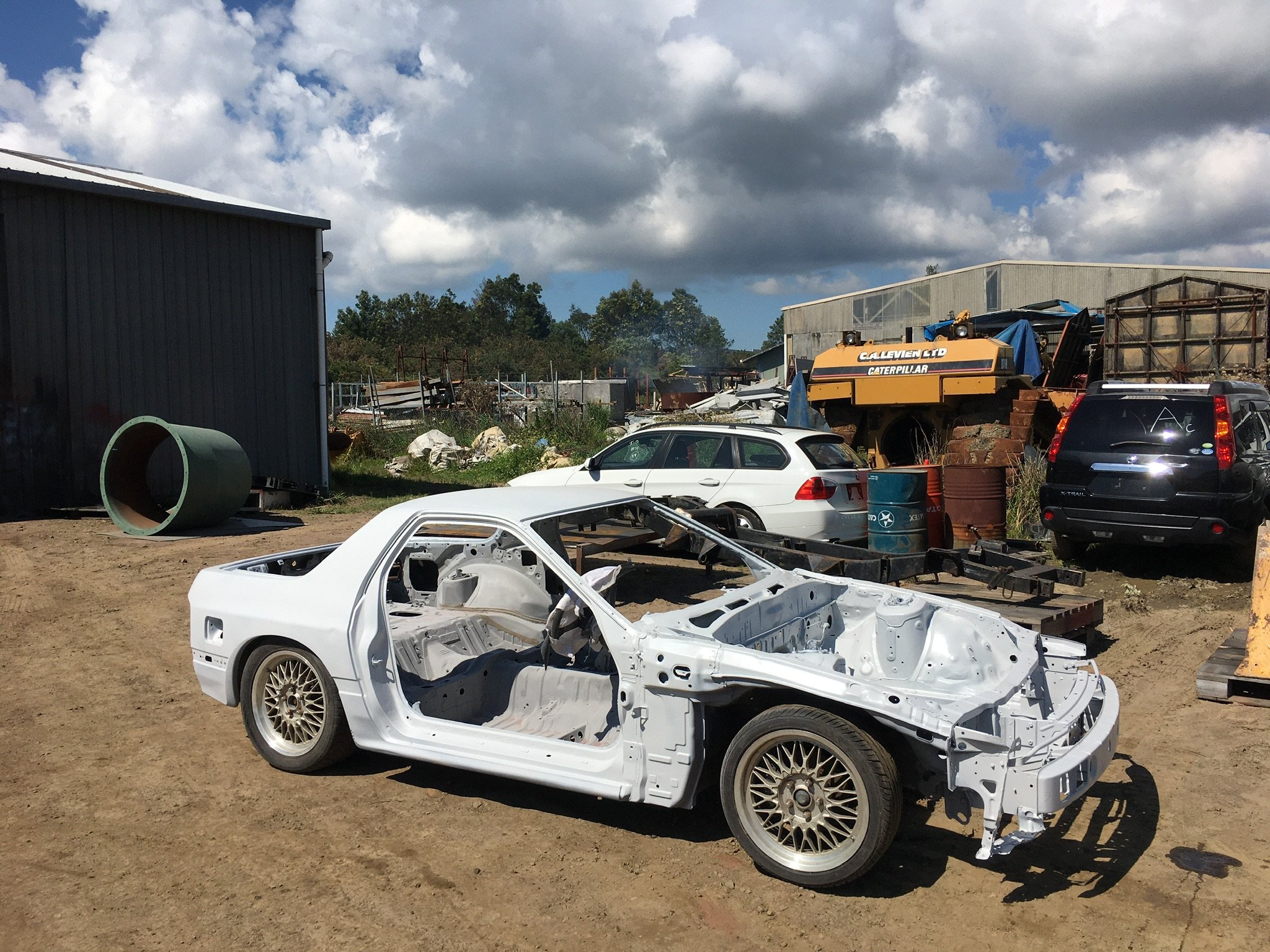
Been busy scraping all of the yellow off the car, whoever painted it last did a terrible job and the paint has been flaking off/coming off when you stick tape to it so thats been fun. also got paper back from MSNZ for my homologation, stripped all the sound deadening out of the inside and its all sanded ready for primer and top coat. also did the rear tubs, cut out as much as i could for future slam/travel.9 points
-
goddam dude, this project just keeps stepping up a notch9 points
-
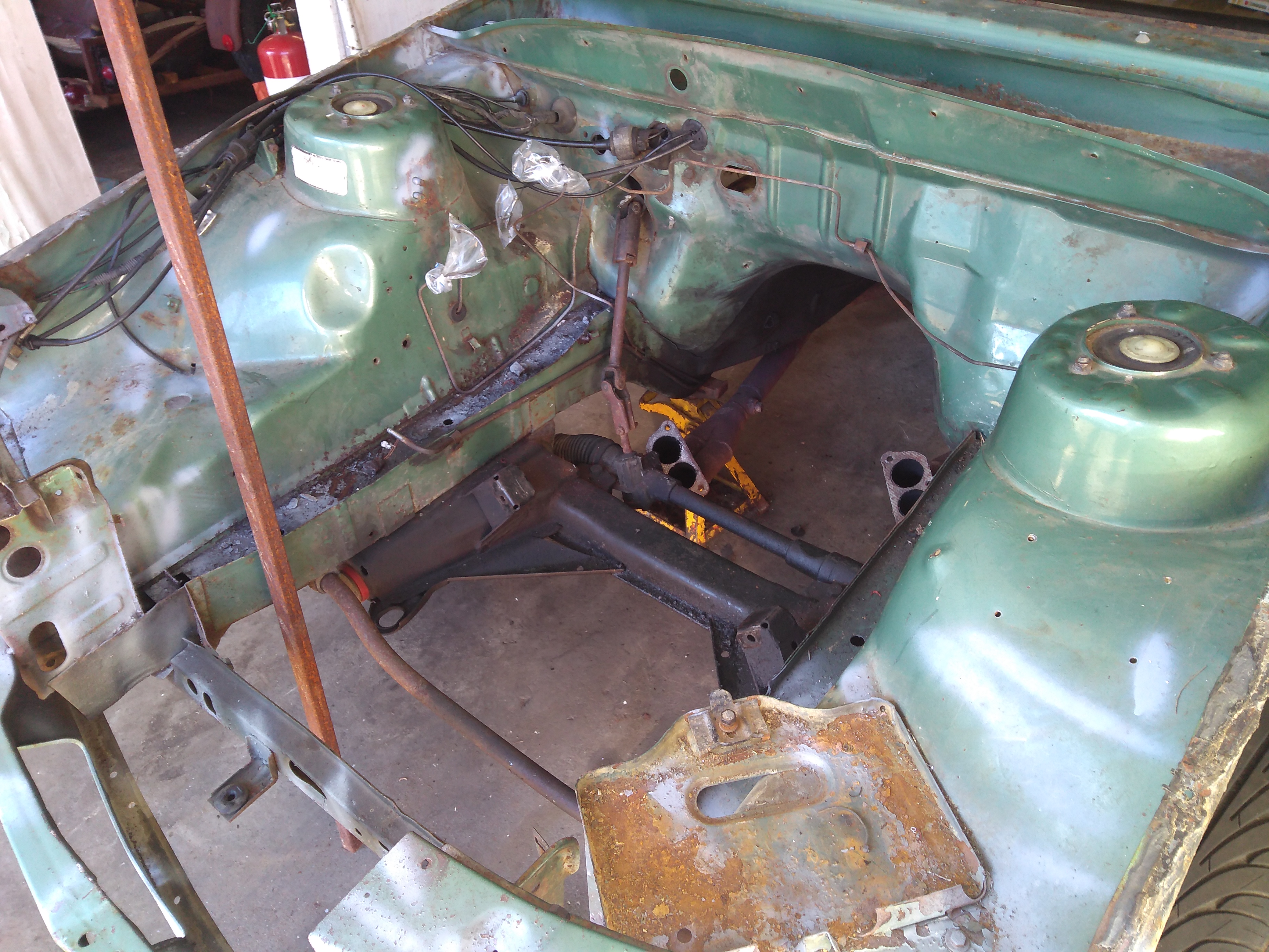
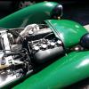
Just look at the difference... I am fully stoked - updated 29th December with latest photo to show actual engine bay comparison with subframe etc installed Before During After
7 points
-
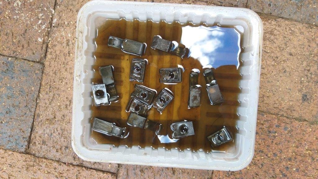
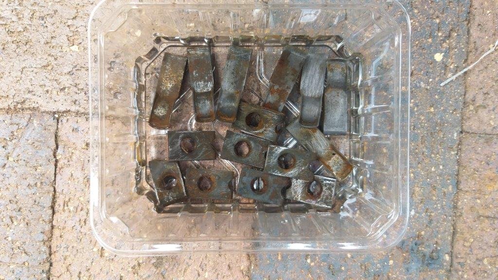
Well, not really, it's just the result of some small crusty looking clips that sat in a vinegar bath for a few days. Gave them a quick once over with a Stanley blade to get off the stubborn bits, soaked them in a bit of fuel, then back into the vinegar bath for round number two. Onwards and upwards. Thanks for looking.
5 points
-
The next step was to machine in some traction grooves. I came up with a few ideas in my head along the lines of using a small router with a carbide end mill mounted to the linear rail. But after realizing that could be quite expensive if I kept burning out end mills, I came up with a rather crude yet effective method, albeit extremely slow. I mounted a chamfer tool 90 degrees on the compound slide and ran it along the face almost like a shaper would, but slower. This seemed to work pretty well on the first test cut, so I carried on with this method, and used the same carbide tip for all 475 grooves (much cheaper than carbide end mills) When I say slow... Each groove took 7 passes to get a decent depth and a decent looking cut. One pass taking around 4 minutes, times 7 for every groove, times 475 grooves = 13,300 minutes or 220 hours. I had done well over half before the lock down in April/March - I then spent 10-11 hours a day for the first 7 days of lock down finishing it off. I tried several times to speed the process up, but that was the sweet spot with this method unfortunately. It also took some time to figure out the best quality cut. (blunt tip worked best in the end) There are a few cuts with tearing along the edges, but over all I'm happy with the outcome - it should do the job at least.5 points
-
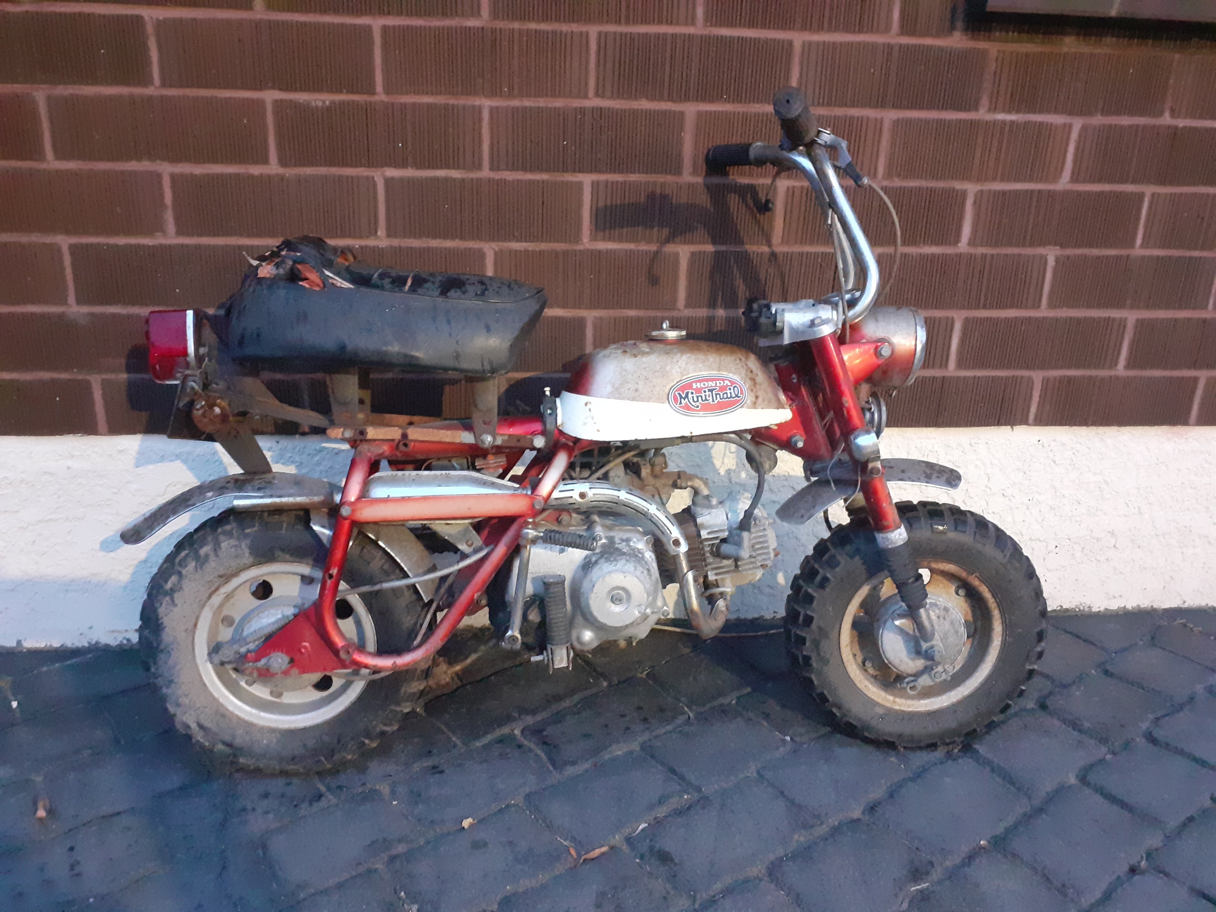
About a year ago this Honda Mini Trail turned up at a mates place with a couple of busted modern Chinese scooters. I expressed an interest in obtaining it & was able to collect it the other night. From what I can tell so far it's a 1970 or 1971 Z50AK2, last of the hard tails. Seems to be mostly complete, just missing front brake line & indicator lenses. Plans are restore the mechanicals, leave the aesthetics alone as much as possible and hopefully get it on the road. Seems to be a lot of repro parts available, anyone on here able to comment on quality? Or good source of stuff? Otherwise stay tuned for pictures of 6ft6 idiot attempting to ride ridiculous tiny bike.
4 points
-
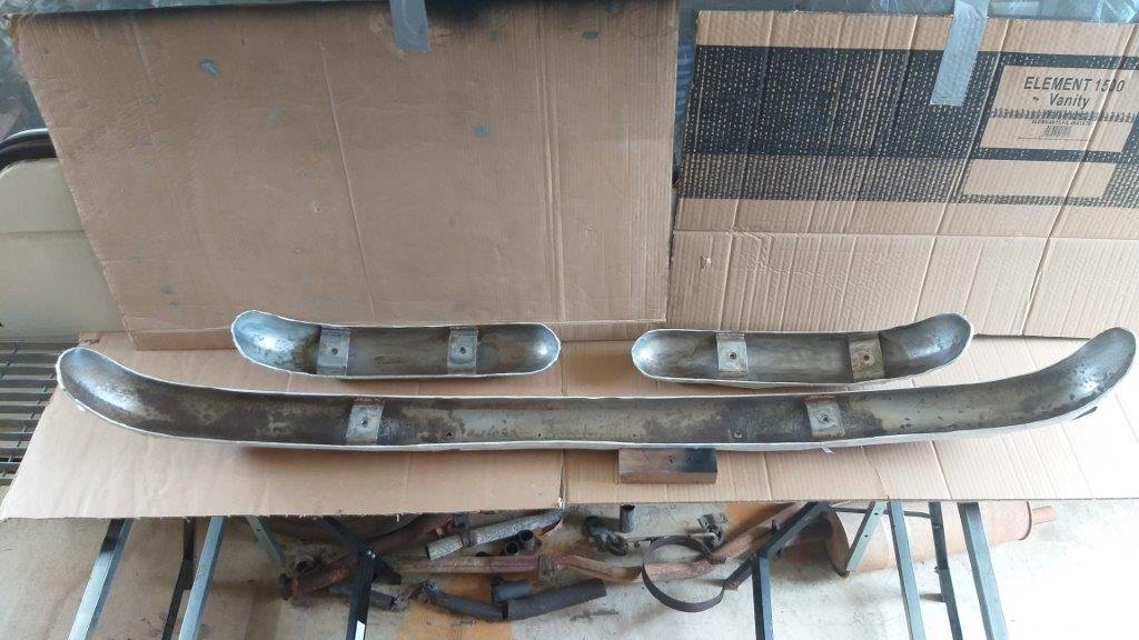
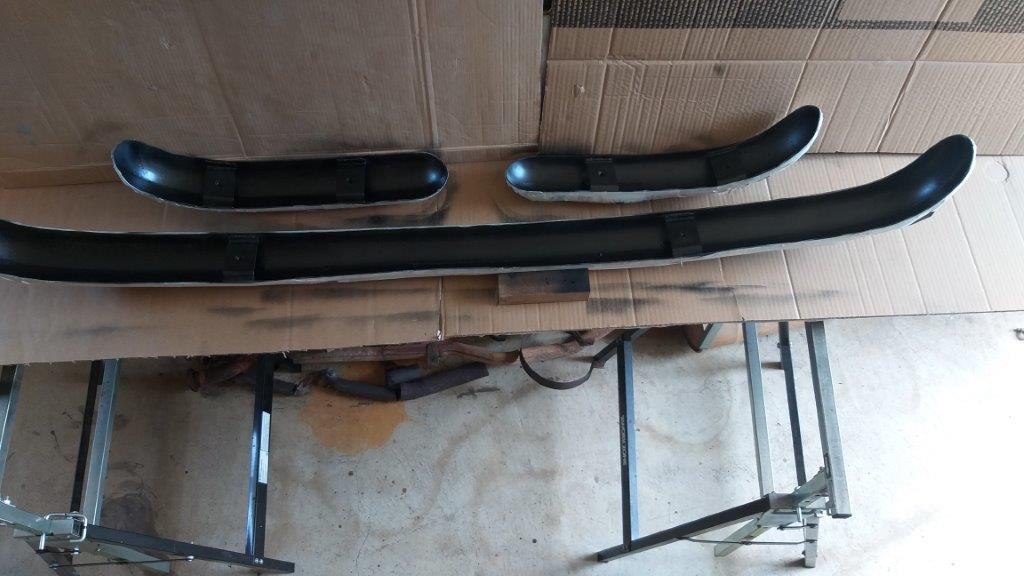
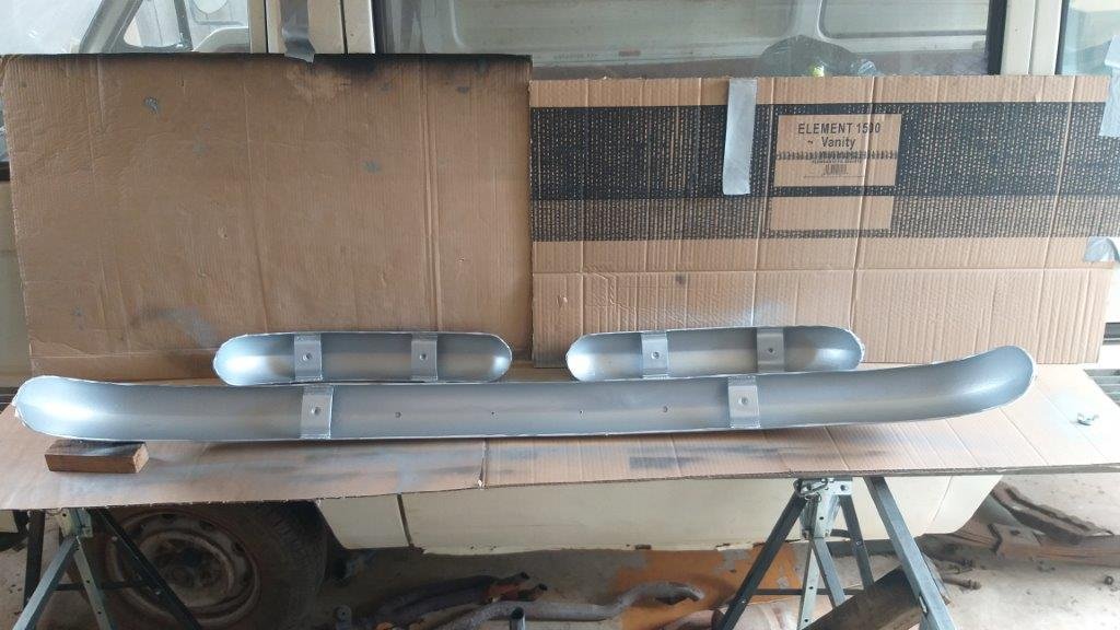
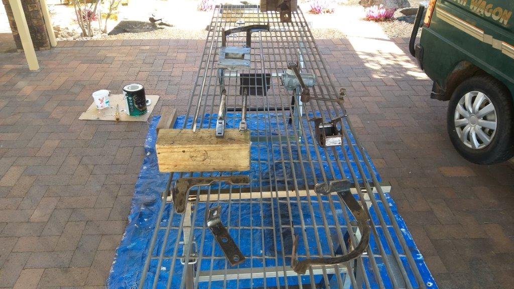
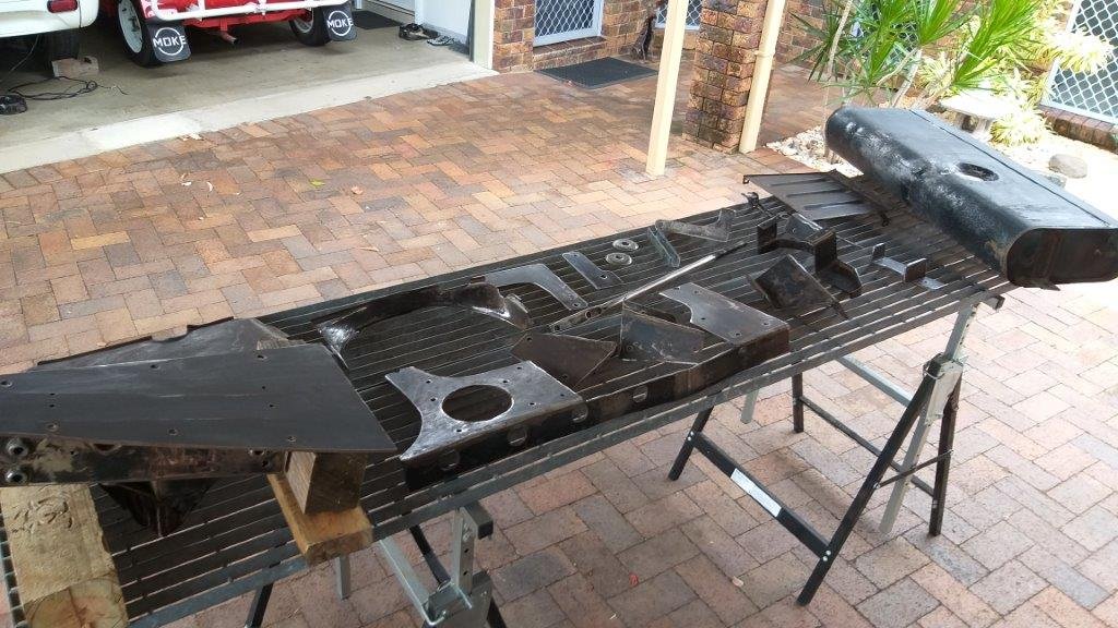
I'm still donkey deep in cleaning and painting all of the smaller parts before final assembly. After spending a bit of time sanding down the backs of the bumpers I declared them as good as I was going to get them. Chucked on a few coats of combination rust converter / primer followed by top coats of galv paint and I'll call them done. Hopefully that should protect them for a few more years.
4 points
-
4 points
-
Definitely the best turnout in a long time, let’s hope we continue along the same lines in the new year!
3 points
-
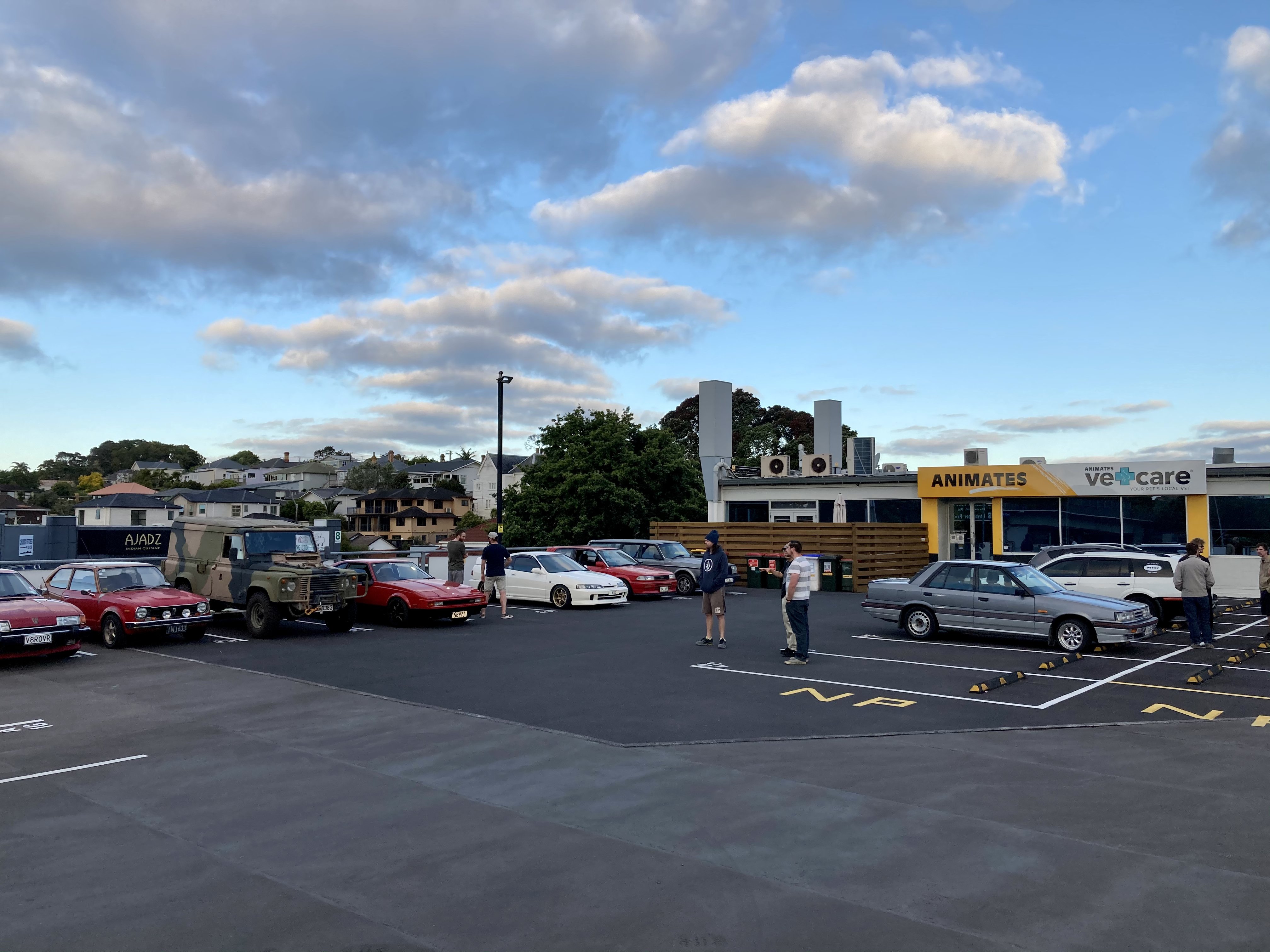
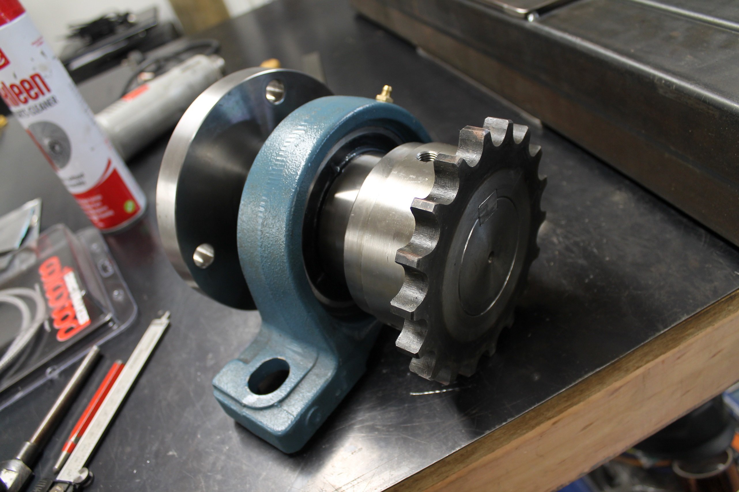
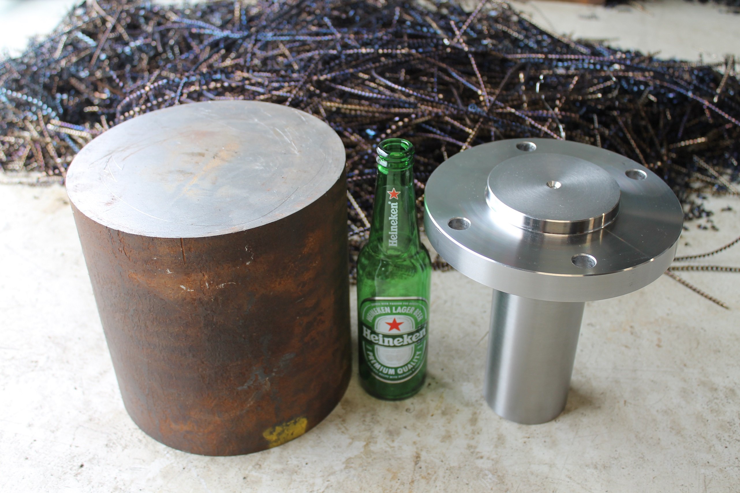
I went to a local engineer who let me borrow his mill to cut the keyway into the hub, GC! - I then had to wait another 6 weeks to get him to cut the key into the 8018 chain coupling Another issue was the keyway in the shaft for the roller. Being to large to mill, I had to spend an entire day cutting it by hand. Angle grinder, die grinder then hand file finished, being careful to get it as close to perfect as I could and not over cut it. PS the sleeve was welded using a series of hot tacks to keep it from moving hence the ugly welds Sent the roll to Qualtex in Hamilton to have it properly balanced. It turns out my balance weights were actually in the correct location, just not heavy enough! Well worth the money considering the fine tolerance they balanced it to.
3 points
-
It selects the voltage and amperage to suit the wire feed speed you have chosen and you have +/-20% for the voltage and inductance. For general fabrication I have set it to +10% on both and that works mint, the weld beads were a bit nuggety on the default setting. for panel/rust repairs I set it to the lowest feed speed and -10% voltage and that worked mint too.2 points
-
i was just reading this post, stick to the known brands like painless there are some cheap knockoffs around, they are the easiest way to do a rewire from scratch only thing worth addding is relays for heavy loads like headlights, grab a factory diagram for the commodore and give it a go (dont just cut the old loom out may need to trace out heater and wiper wiring)2 points
-
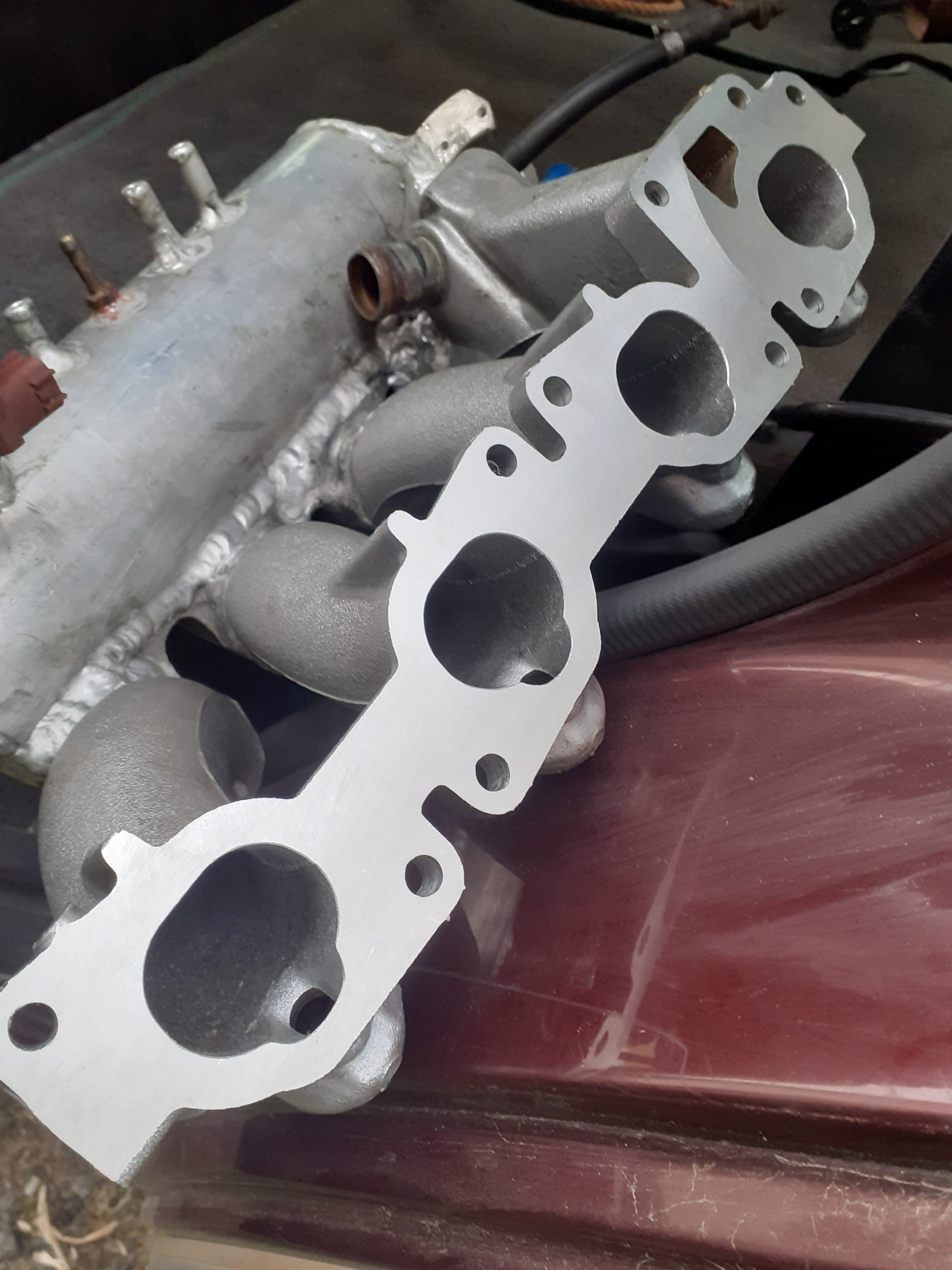
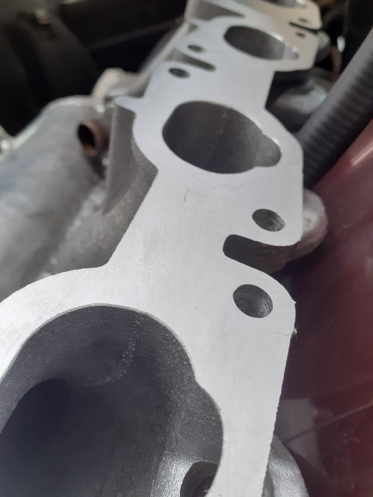
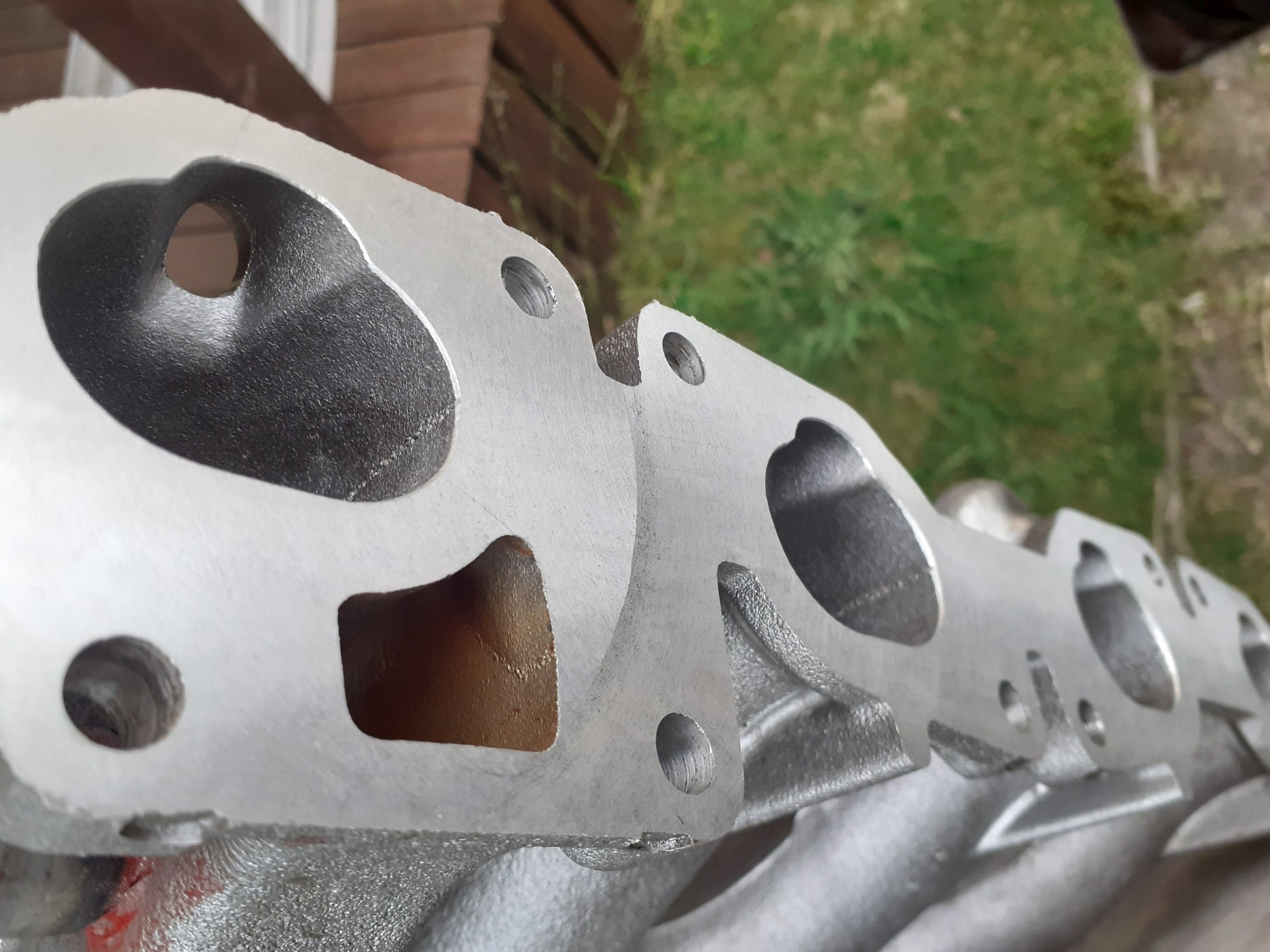
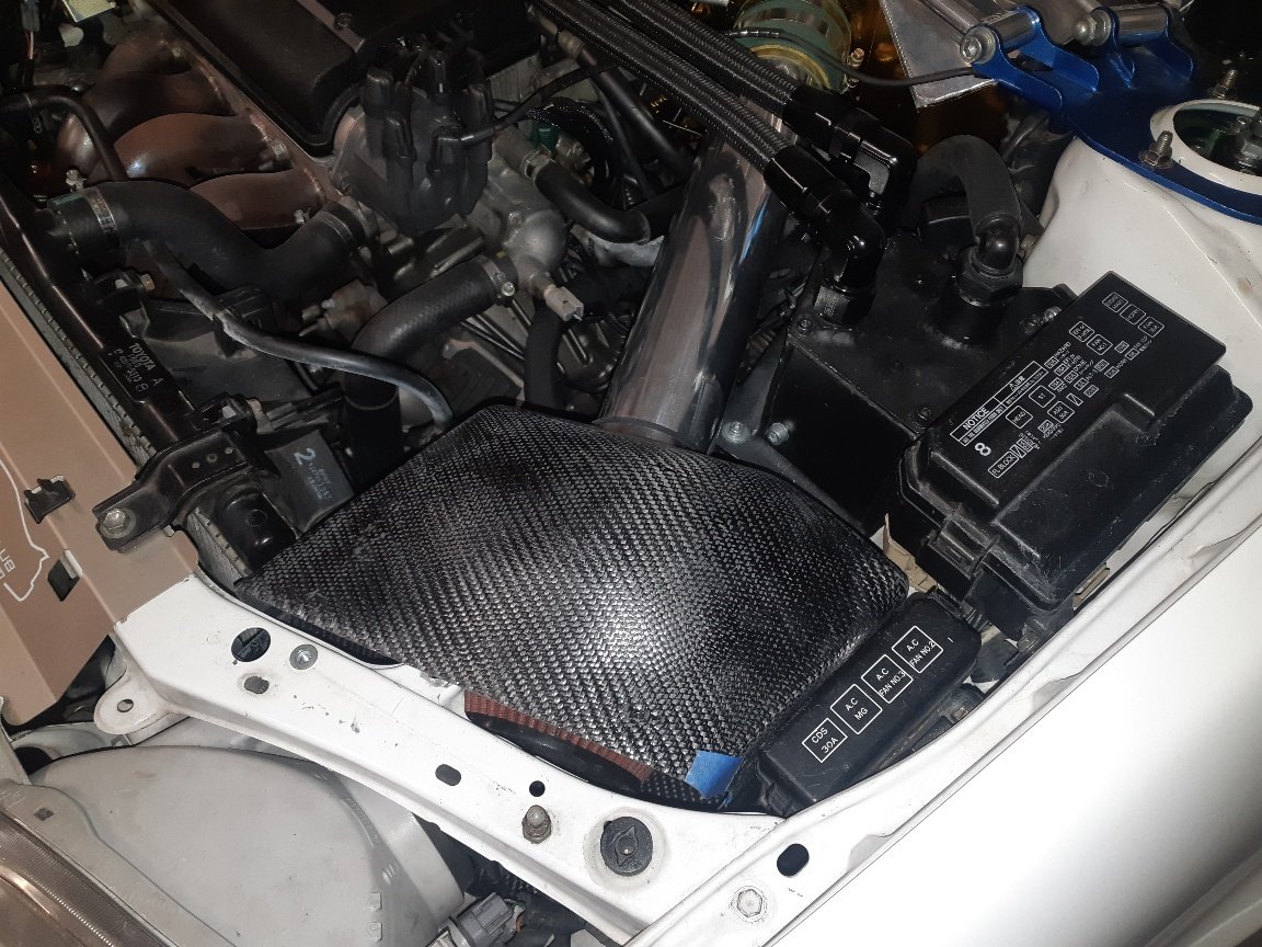
Milled the intake at work, was warped by about 1/2 mm on each end, had to be done or else its gonna crack welds in the future, is now dead straight, will be doing more work in the coming 2 weeks !
2 points
-
Even better, 3 year wofs2 points
-
2 points
-
2 points
-
It was about this point I had a bit of a problem on my hands. For some reason one end of the shaft had almost 0.5mm run out (warpage from welding?) which I never really noticed during machining I ended up sleeving the shaft either end to 90mm until I had the whole lot within 0.1mm - which was a bit of drama in itself. I also attempted to balance it myself at home using a chinese vibration meter, a bit of trial and error and plotting the data as a spread sheet I managed to significantly improve the balance - however getting it up over 400rpm was a little scary when it wanted to take off across the workshop - so I gave up. Photo of the sleeved shaft, new 90mm bearing and balance weight. I then machined some hubs for the Telma retarder out of 200mm 1045. 50kg down to 9kg
2 points
-
Since I can only safely mix 30kg of sand at once Ive made some partitions over the pattern for 30kg sections. Will do some sequence of removing walls and work along the pattern. Probably key the sand together as I go so hopefully it doesnt shift around. The base is an overly complicated 30mm spacer that the inner cores align to. Could have done it out of wood but when you have a big printer why not! Once Ive figured out if the pattern works I will be able to fill it at the foundry in one go without partitions.2 points
-
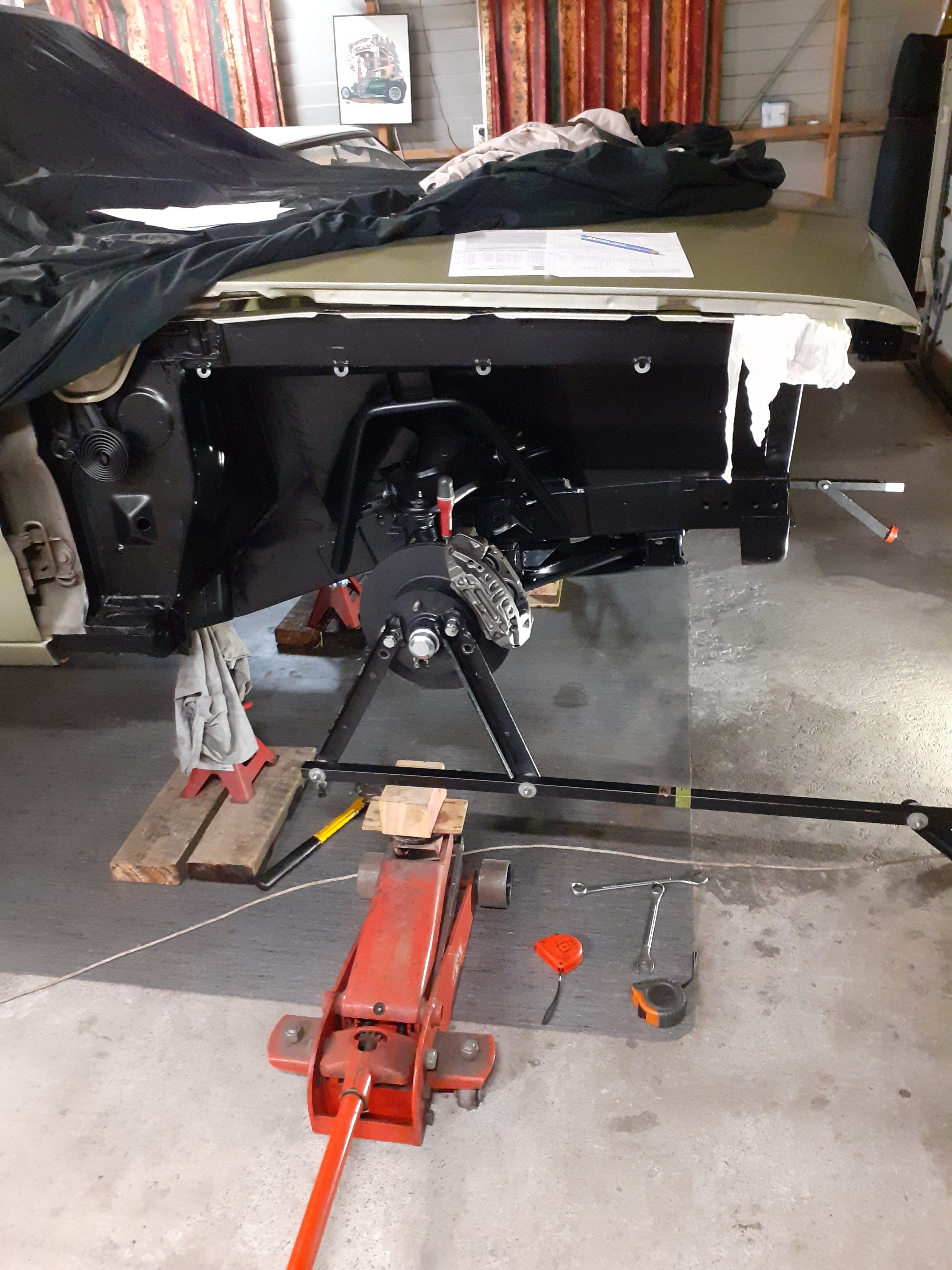
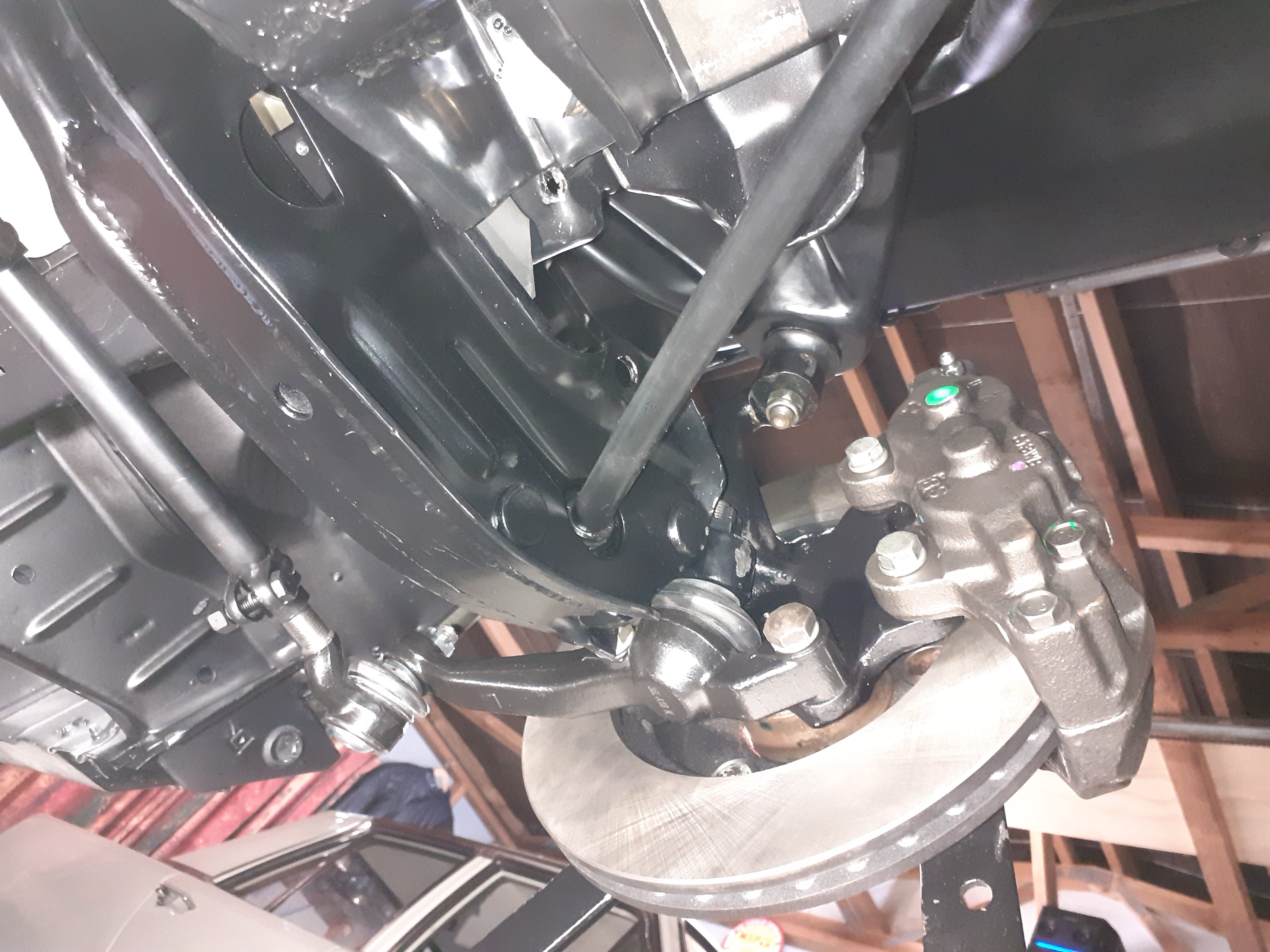
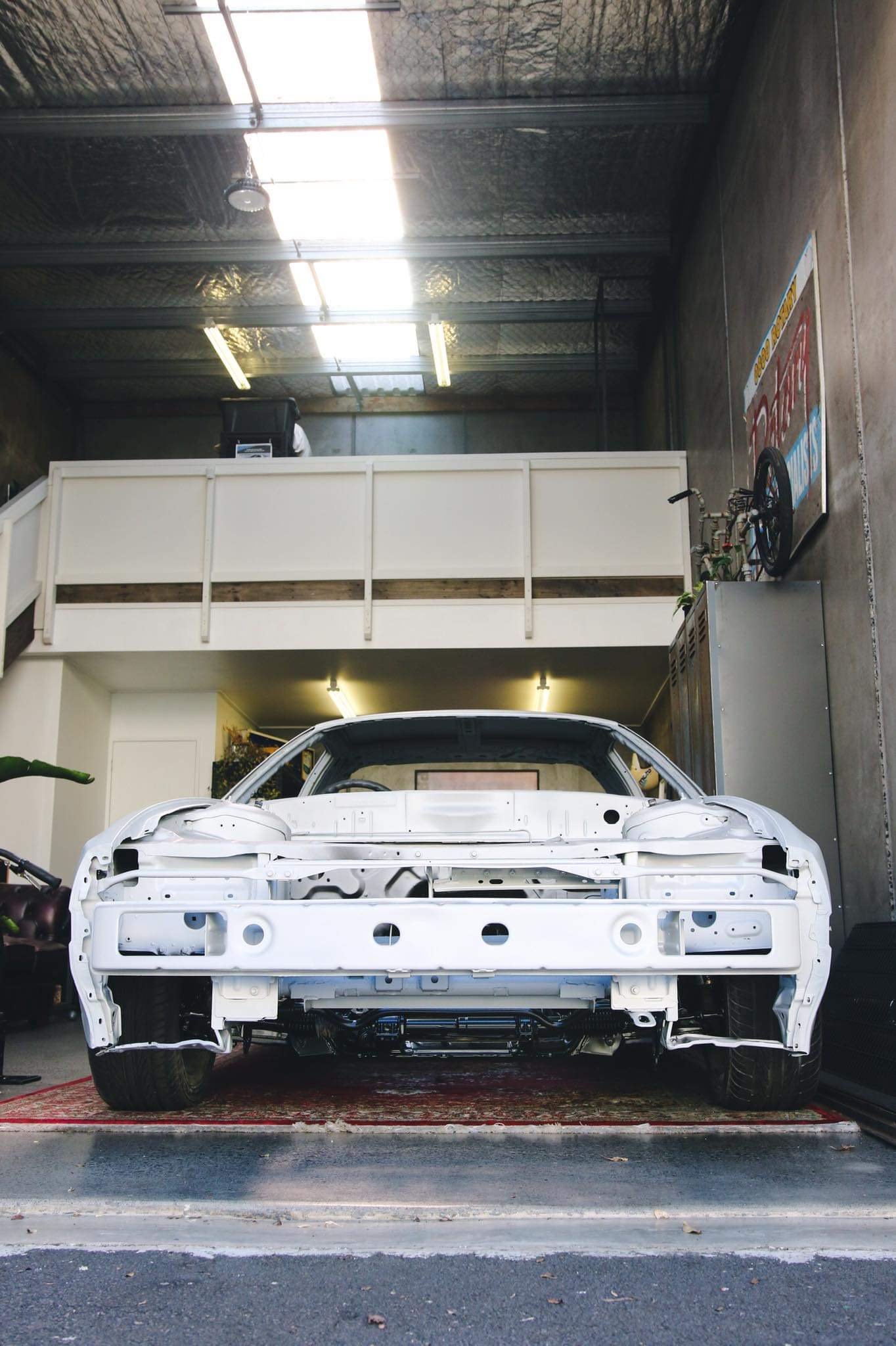
That's the panelbeaters 99% done. Now to find a few hours to bolt all the front suspension back in and get it rolling again.
2 points
-
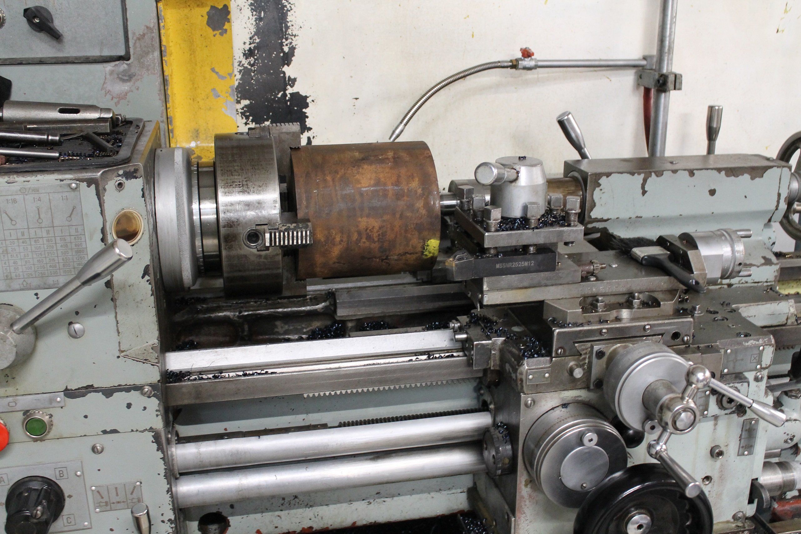
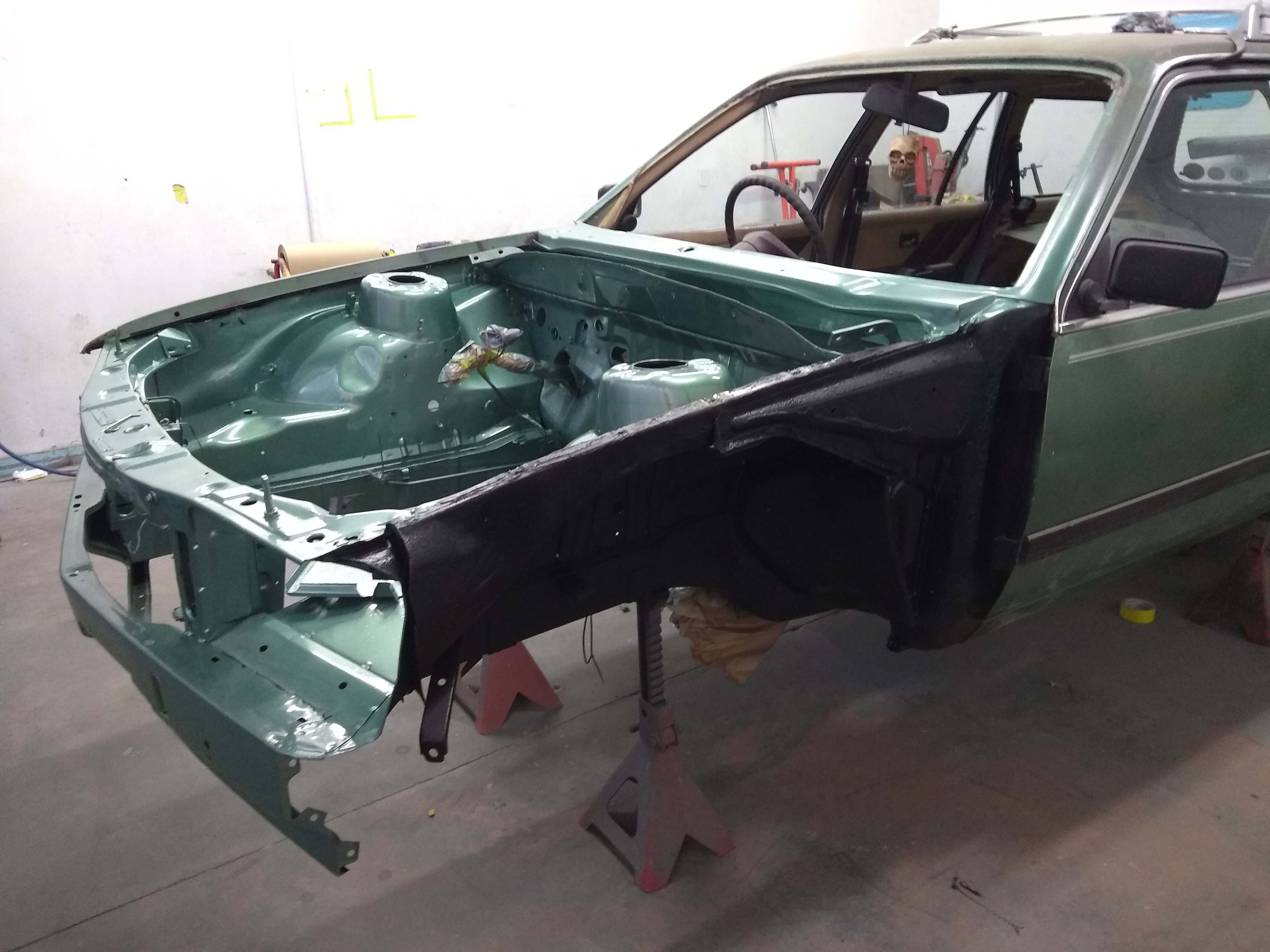
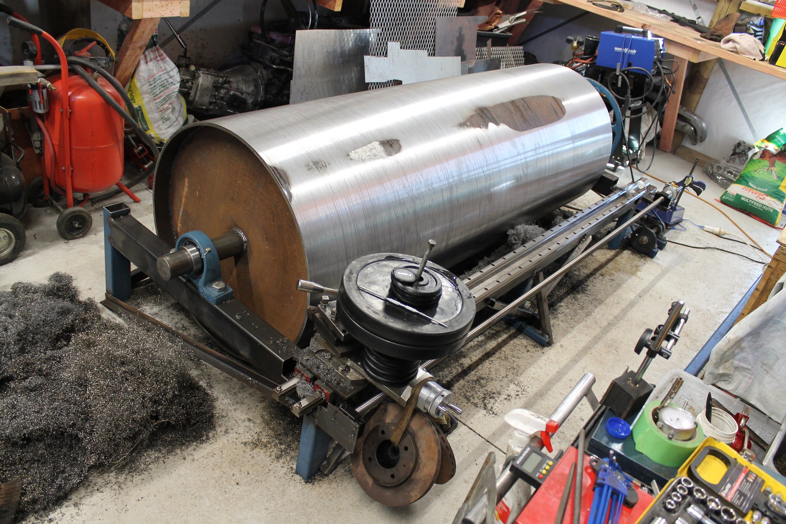
The ideal speed for machining something so large would probably be 50rpm or less. So I bought an old concrete mixer pulley off trademe (around 560mm) and a 50mm pulley for the 3/4hp electric motor I scored from work. This gave me about 130rpm. This worked pretty well at first as I machined off the high spots, but as time went on and the cuts became longer things got complicated. The carbide inserts were over heating and wearing out well before half a pass. I found a home built saw bench on facebook marketplace for cheap, which had some different size pulleys and a stand alone shaft with bearings, so I snapped it up. I then modified my original setup and managed to gear it down using the shaft from the saw bench with an isuzu crank pulley on the other end, to around 62rpm. The lower surface speed was much better but the tips were still wearing out before a full pass, and I was starting to fight some serious chatter. It became apparent that the linear rail support had some flex, causing the compound slide to tilt forward and spring back causing the chatter. I braced it up with some random offcuts which made a big difference. (The linear rails should have ideally been much further apart and properly supported) Still getting chatter, I added 30+ kg to the back of the compound slide. This was enough band-aiding to get me through to the end, without changing the whole thing completely. I also upgraded from a battery drill with a cable tied trigger to a Nema 34 stepper as I needed a much slower feed rate.
2 points
-
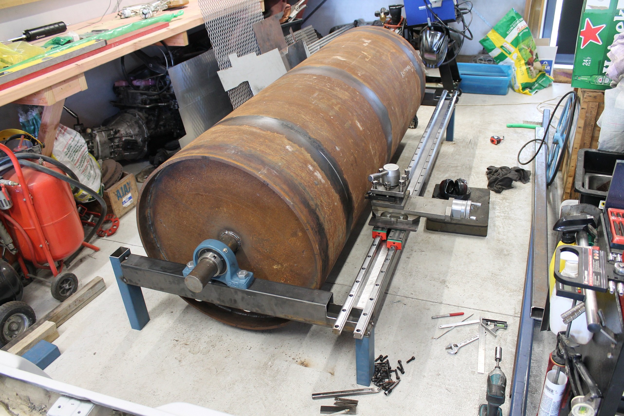
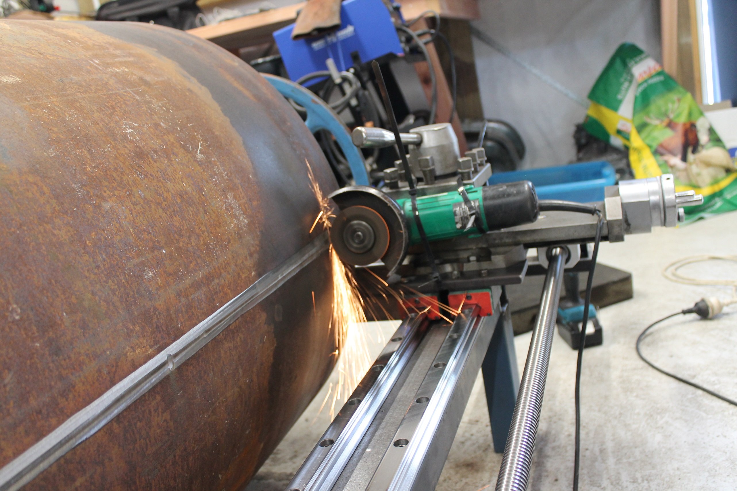
While I was fabricating the roller, I visited a bunch of engineers in the region and found that no one had a lathe big enough to machine it. Bugger. After getting some quotes from further abroad that would have blown my entire budget by themselves (15-20k). I decided that I'd just build my own lathe.. I jumped onto Ebay and ordered the cheapest set of linear rails I could find, including the ball screw and bearing blocks. 3-4 weeks later I got set to mocking up the "lathe" using the compound slide from my Stanko mounted to some adapters. Spinning the roll by hand with the compound slide clamped to the linear rail, I took the first test cut. "Fuuck yeah, this'll work" I said.. It would have taken forever to machine the 3mm x 25mm weld bead off, but I remember once when @kpr mounted his angle grinder in the lathe to cut through some hardening on a set of axles from memory? (that image is burnt into my mind, probably thinking it might be a useful trick one day. cheers dude!) The grinder worked really well and made short work of it. Spinning the ball screw with a battery drill.
2 points
-
Good score! Lots of parts available, even genuine Honda if you find the right part numbers (via partzilla etc) and order from Webike.Jp genuine parts section. There’s also Aconohonda in Te Aroha, same thing with part numbers: https://www.anacondaltd.co.nz Aftermarket, quality is fine, definitely a lot better than the Chinese scooters of back in the day. Darren is our original aftermarket monkey / Honda part supplier: https://www.shore50s.co.nz/store/c1/Featured_Products.html and just recently mBike have come into the NZ market with mostly AliExpress spec Honda specific goods at decent prices. https://www.mbike.co.nz Hope this helps! Looking forward to updates / If you ever want to sell it let me know1 point
-
https://www.nissanforums.com/threads/reading-error-codes-on-x-trail.99211/ That's what I used. The post with all the codes has the instructions at the bottom. It took me a few goes but it worked in the end. Have a watch/timer handy1 point
-
Spit fires and eagers or ban. /ling.1 point
-
@kyteler endorses gold mesh1 point
-
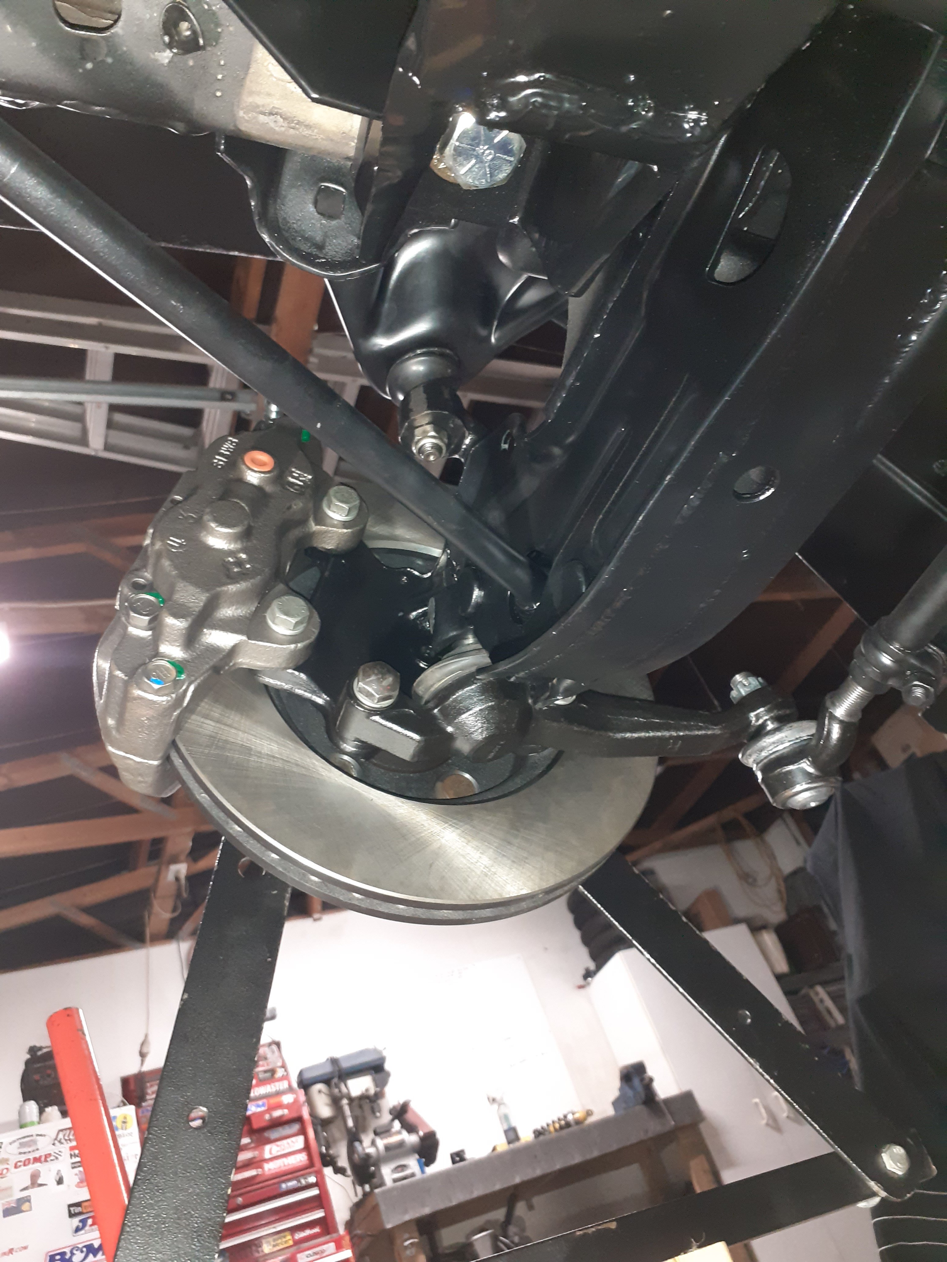
Front brake outer seal has either gone to shit or been goobed with black silicon. The black goop down in the corner parts of the caliper seem to agree with it being silicon. It's also on the piston, so that's why it's sticking. Caliper and piston are otherwise in excellent condition so I think they probably hamfisted that seal and panicked. Throw a seal kit at it I'd say Parts are cheap online but don't wanna wait for a new caliper so will pay the same price for a seal kit locally lol
1 point
-
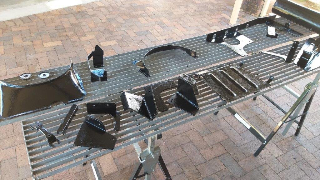
Spent yesterday preparing the second batch of parts for paint. A few needed some welding touch ups whilst others just needed a good de greasing followed by tickle with a flapper disc and a bit of wire wheeling. It's relatively mindless work, but needs to be done. Managed to get a first coat on them this morning. While they were drying I cut some extra thread into the rear axle U bolts necessitated by the removal of the two lower leaf springs. So that's another small job ticked off the list.
1 point
-
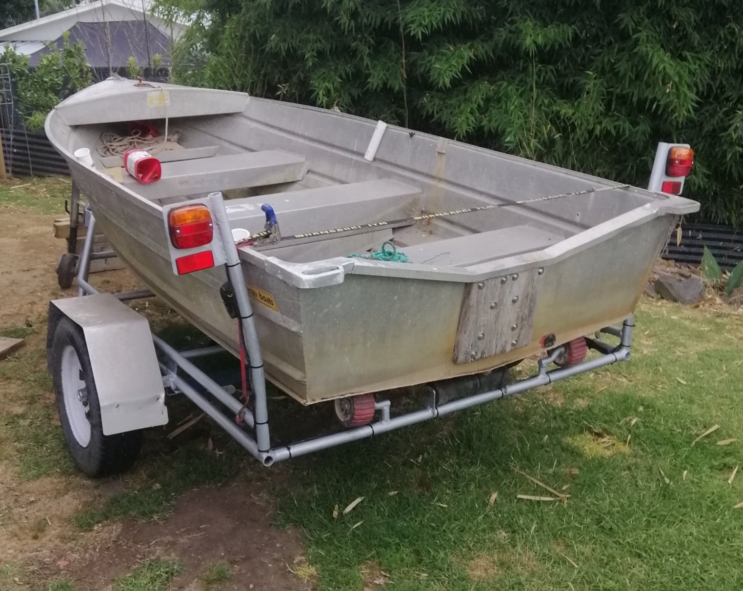
Scored some 13x5 trailer wheels for $180 locally off Marketplace. Smashed out an axle this afternoon. Unfortunately the new wheels don't go into the spare carrier. Track has increased 60mm or so, about 20mm higher than before. Left to do. Fabricate a new spare carrier. Cut the old one out. Waterblast and paint wheels and axle. Make new wider guard mounts and fit Touch up paint after modifications. WOF. Boat needs engine mounting, I've decided to bolt it on permanent until I can find a 15hp. A complete new drain bung you can operate without a spanner. Wish list is a screen, canopy and a depth sounder. Next year.....
1 point
-
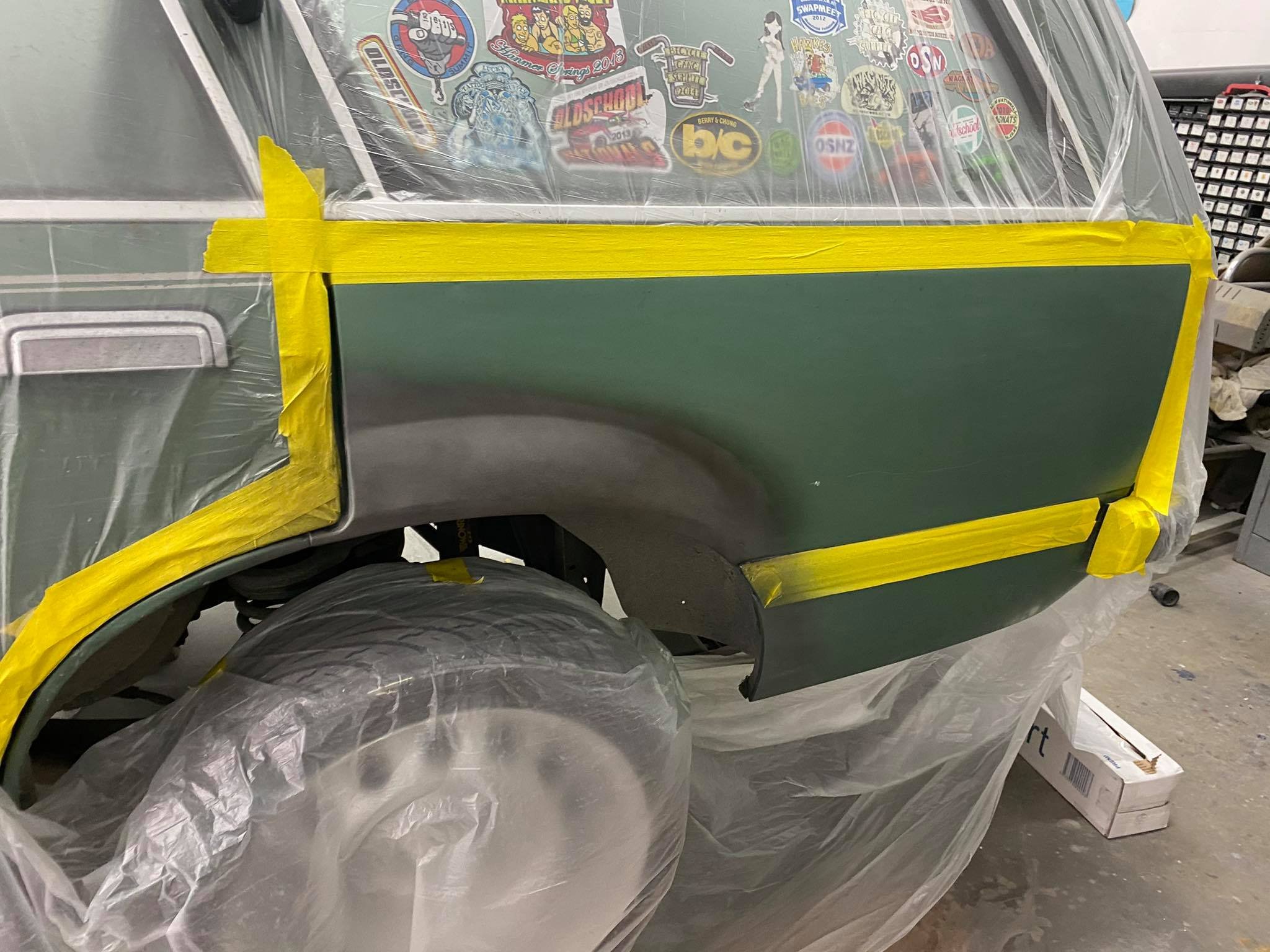
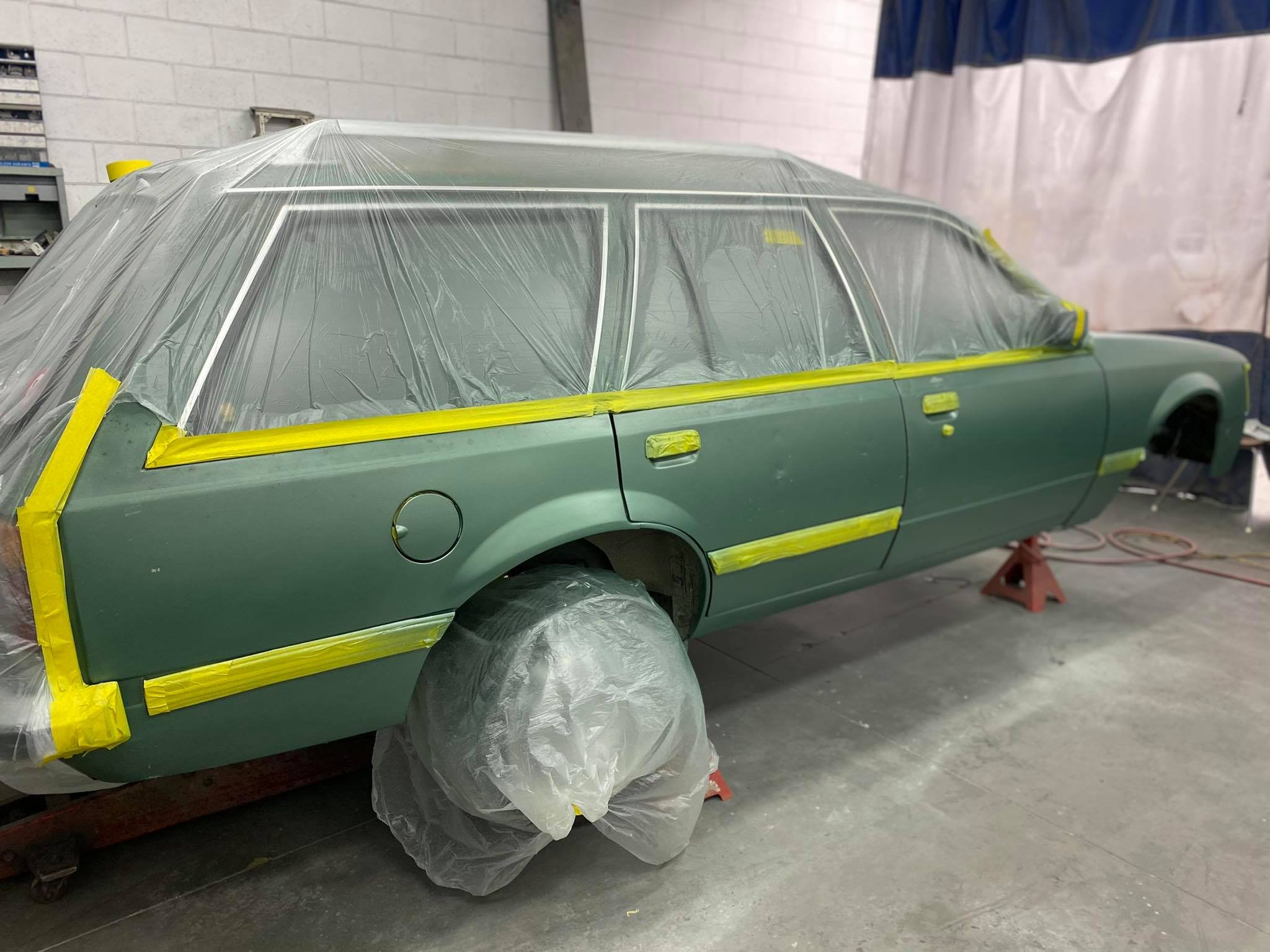
i fucking wiped the car down with prepsol and said to myself "now you take a picture of how the filler/car looks before you put any more paint on it so the nice people can see what you've done" and i didnt take a fucking photo. sorry about that, now all i can show you is a picture very much like the one above, except the car now has less dents. its not straight enough for colour yet but i kind of feel like i could wet sand it with the long boards and get it right from here? maybe not. probably need to 240 grit it now to get it super straight, then another light coat of primer and wet sand. ill probably do that. 2020-12-20_04-44-16 by sheepers, on Flickr1 point
-
So the new joints arrived this time but they were packaged incorrectly and for a different car. Because the theme for this project is buy things at least twice I ordered some more of the 'correct' ones and am now waiting for those to arrive. I was bumbling around in the garage and looked at it and thought 'I wonder if the spindles and brakes fit the other way around ' as the mount holes for the balljoints are angled. Swapped side to side, did a bump steer check , that got it down to 13mm, it had what appeared to be a shit ton of caster and the top ball joint was getting close to binding, so adjusted the top arm a bit and rechecked it, down to 5mm now with camber and caster in the ballpark Other people are having xmas parties, I'm in my garage quite excited at improving my steering and suspension geometry, what a nerd
1 point
-
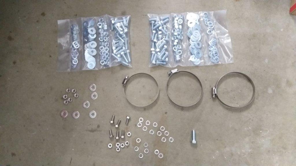
I've been quietly plugging away at a few things over the past week. Managed to paint the first batch of previously fabricated brackets and mounts and grabbed some new fasteners whilst I was in town yesterday, so I can start the re-assembly. The textured paint that I am using throws some ugly looking shadows, so you'll just have to take my word for it that they look much better in real life.
1 point
-
That is farking epic! Great work.1 point
-
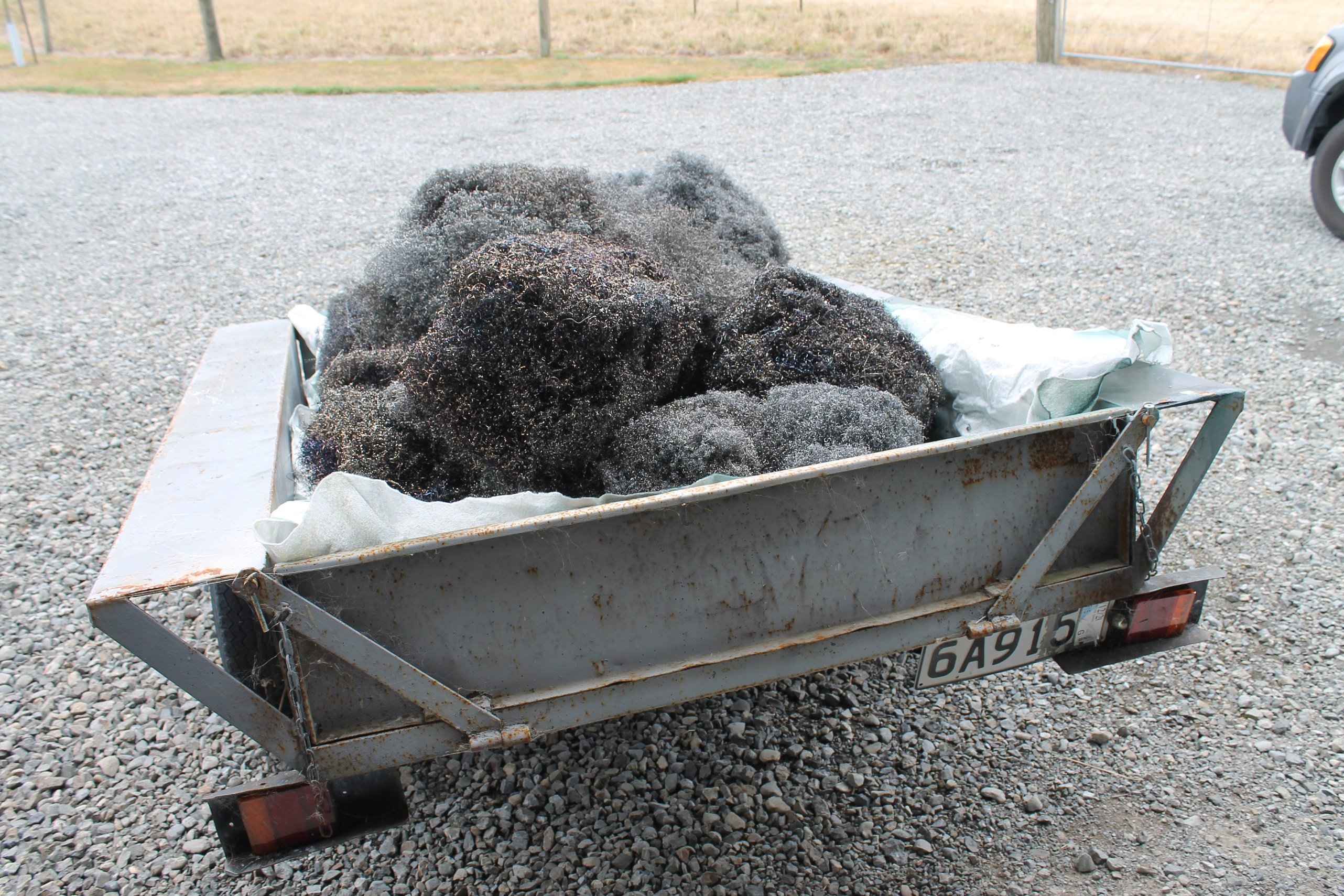
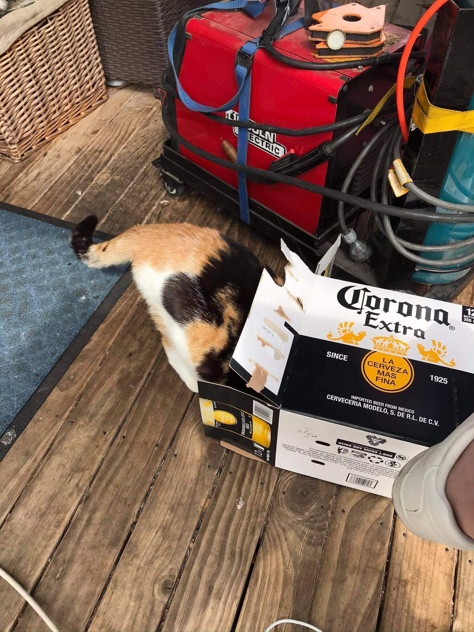
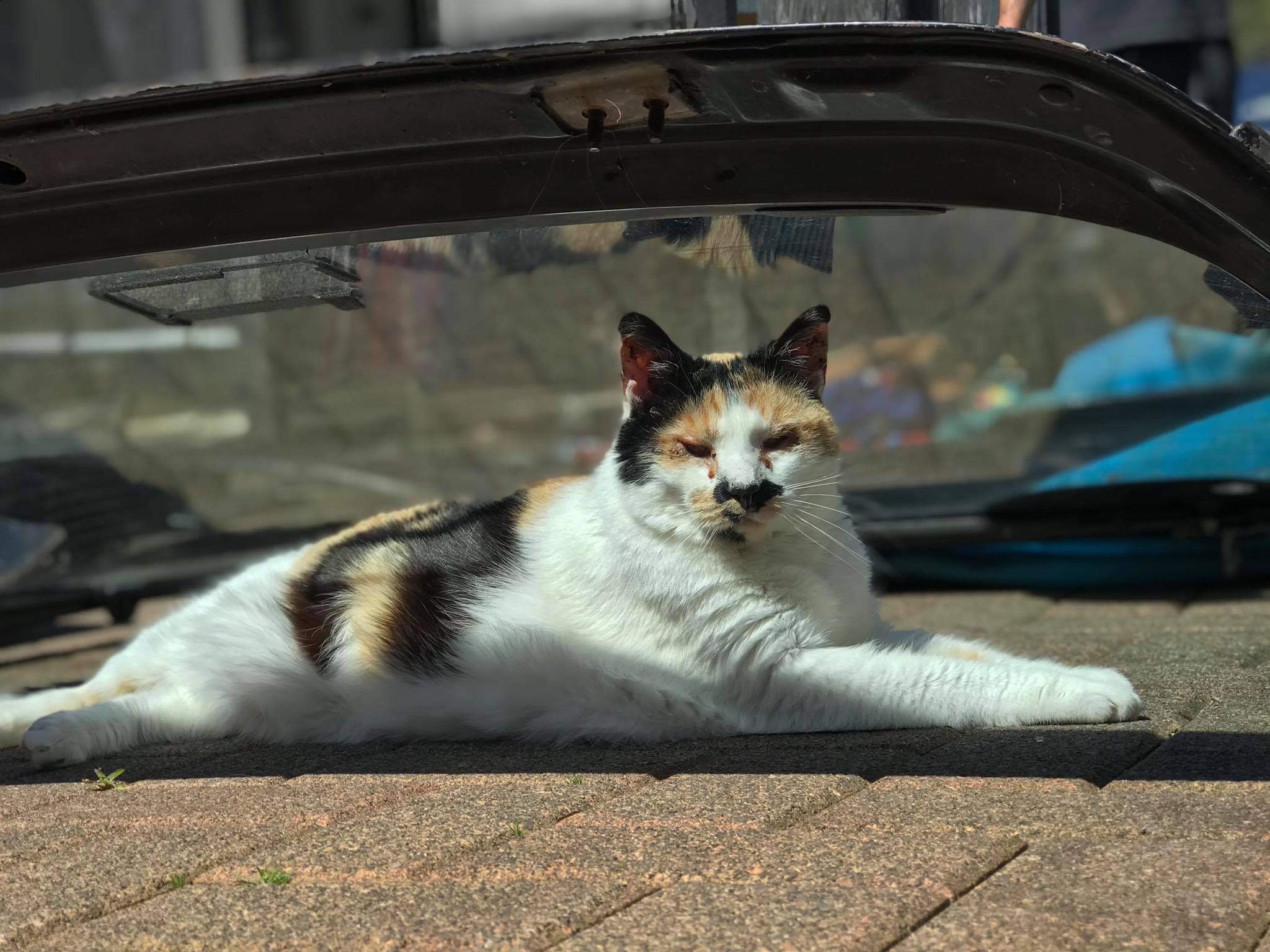
I uploaded a video of my cat who loves to hang out with me in the shed, even when I'm making loads of noise. The video also shows my redneck contraption in action Tortron, I think about 100kg of steel wool was made lol
1 point
-
And you can make a tidy profit in the steel wool business! very rad so far1 point
-
According to my rough math it should suck about 80-100kw + another 5kw (for the retarder rotors) to accelerate the roller over a 6 second ramp run. But not only am I not an engineer, I'm also not a mathematician lol Retarder when cold can fully brake about 150kw at 500 rpm (roller speed) and about 470kw at 1500 rpm and about 620kw at full song (2000rpm) To put it into real terms, using my Gemini for example - makes roughly 40kw at 2500rpm (500rpm roller speed) and 180kw at 7700 (1500rpm roller speed) So the retarder should be able to steady state a car with 2.5 - 3.5 times the power and who knows how much more with ramp runs? Surely 700-800kw? Time will tell.1 point
-
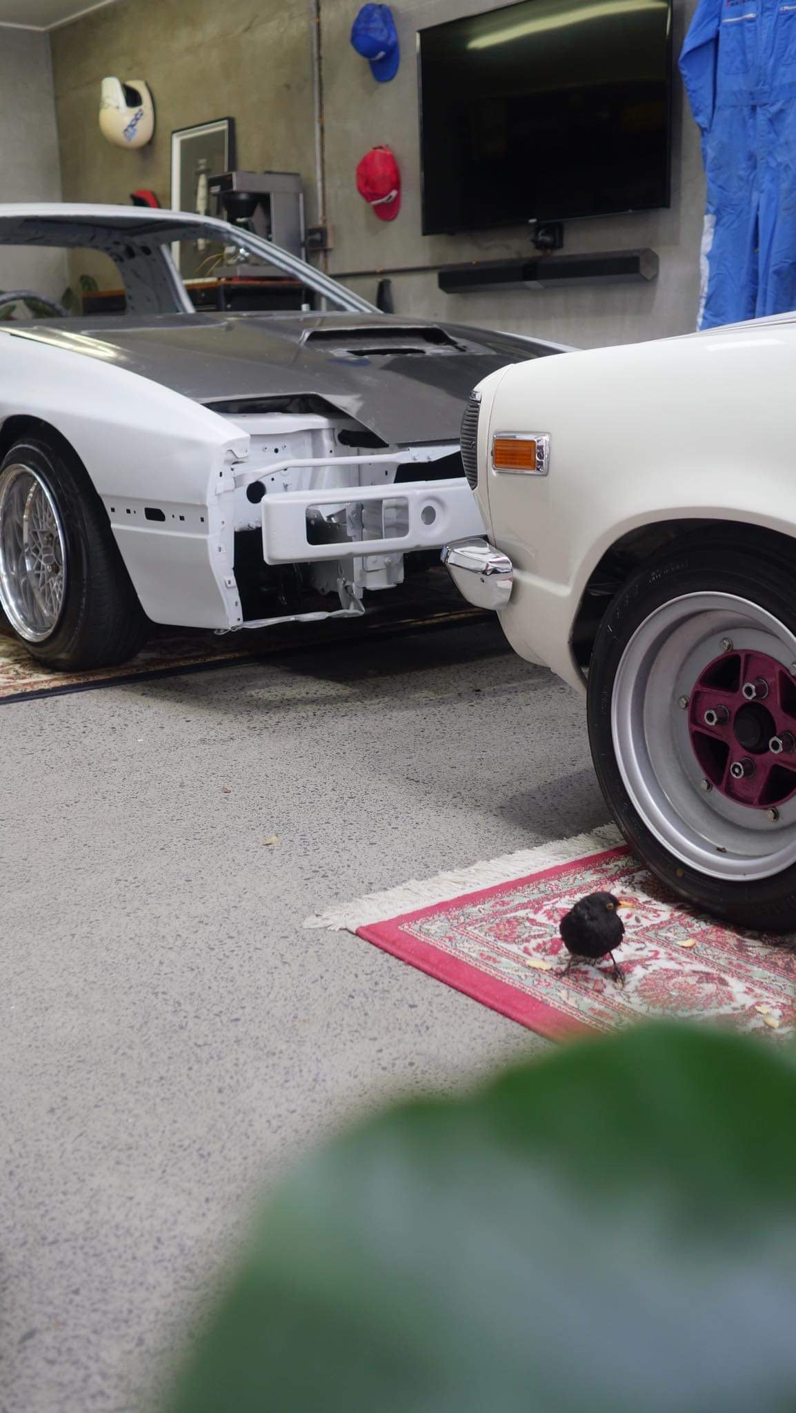
Bonus photos of repaired rust in hatch and helper blackbird who likes to sit next to car and eat meal mates while grinding and welding happens
1 point
-
It was then bought home to start the rust work and to sit and look at while sampling some ouzo and limoncello
1 point
-
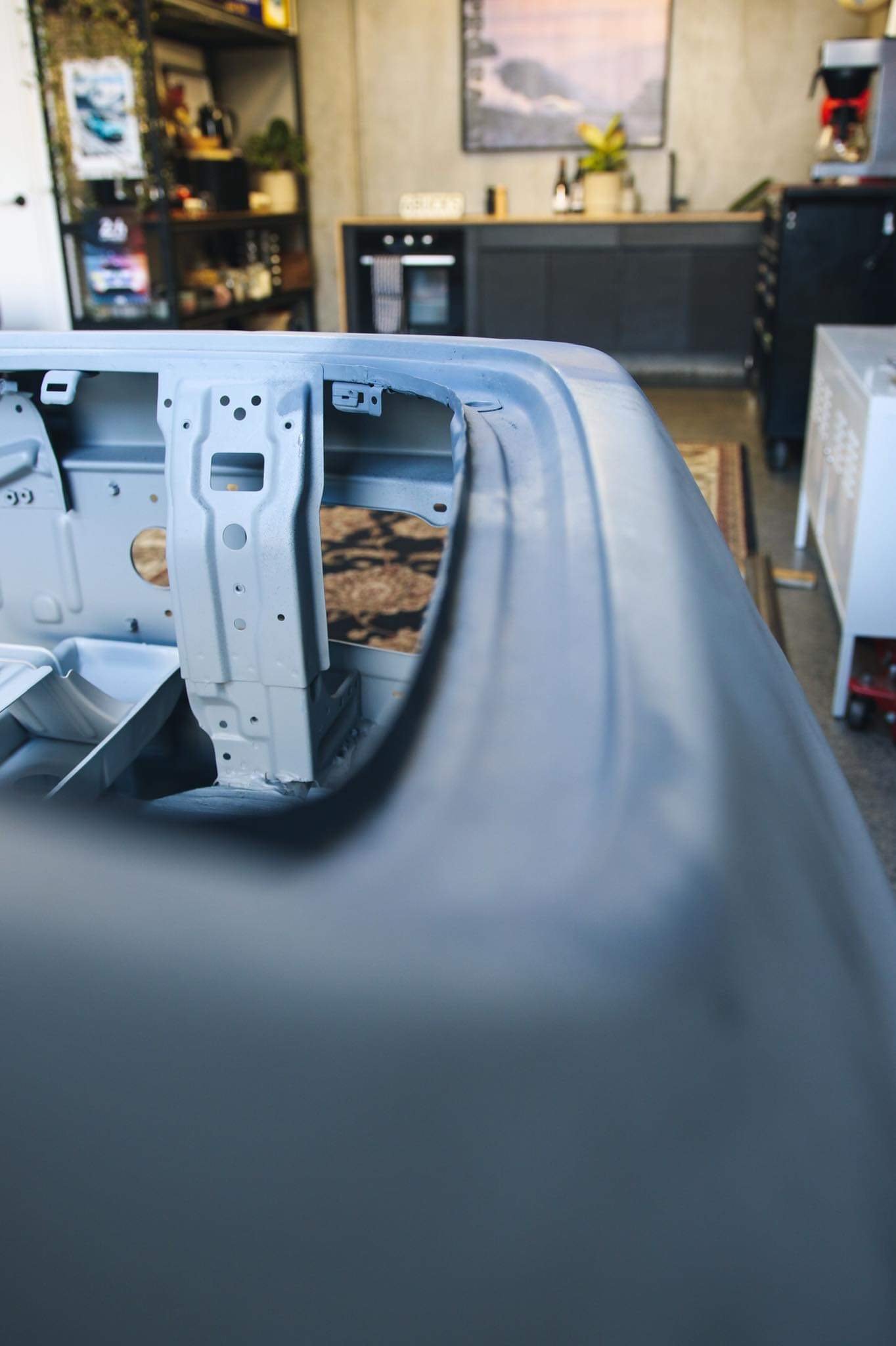
The underside was blasted and painted black which also looks awesome and clean to work on
1 point
-
1 point
-
Floor is all tied in. ready to flip and finish underneath.
1 point
-
Me and my daughter rolled up the door panels today
1 point
-
I can really appreciate these body shops who do tubs and this sort of work after trying it for myself. So much mocking up and working stuff out. I need to work on the panel now that goes up against the quarter panel.
1 point


This leaderboard is set to Auckland/GMT+12:00