Adoom
-
Posts
2188 -
Joined
-
Last visited


Adoom's Achievements
Committed (5/5)
5.3k
Reputation
-
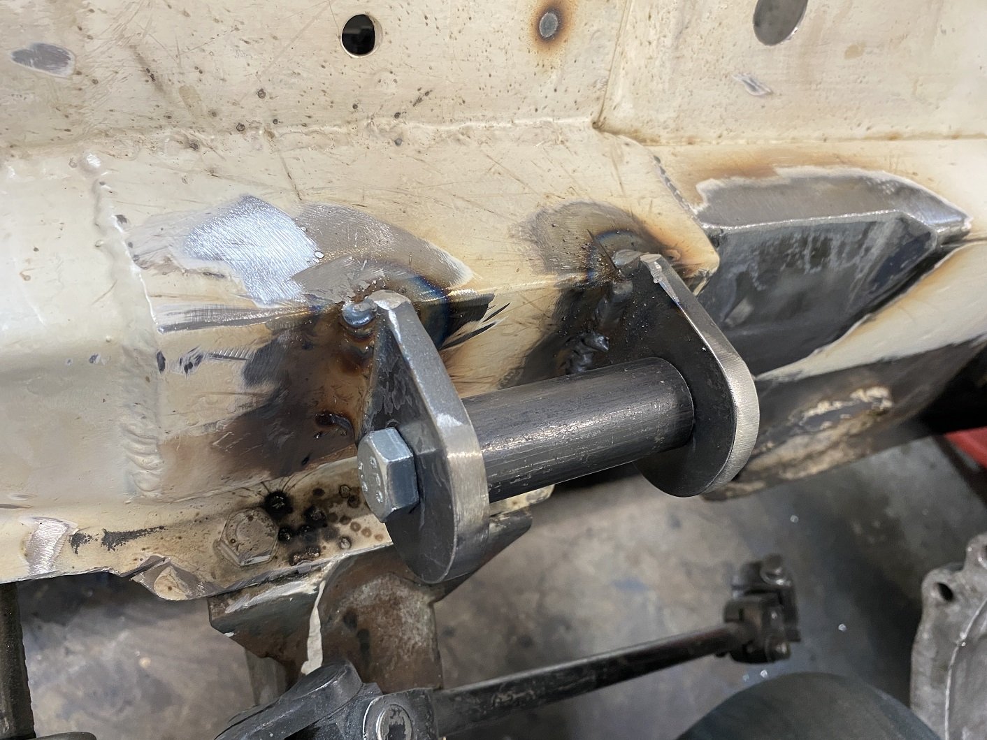
Fuck, I must have spent at least 4 hours grinding the remains of those spring mounts off. There were so many spot welds, I basically has to turn 90% of it into dust on the floor.
-
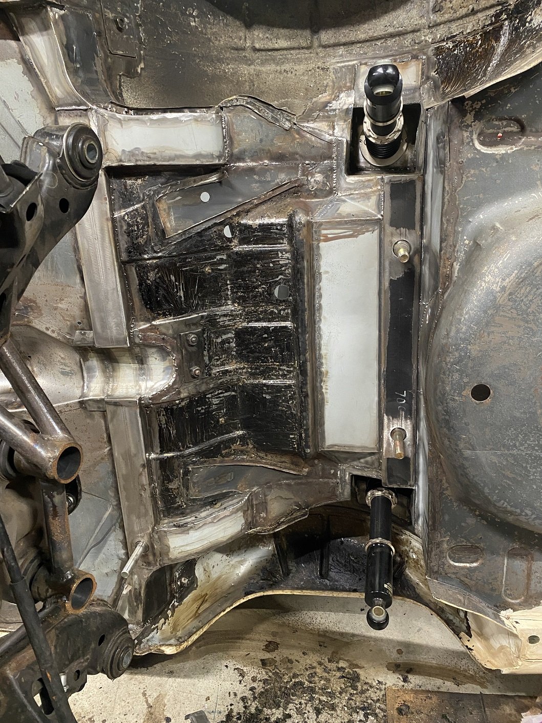
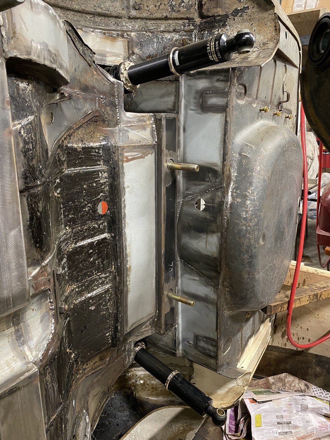
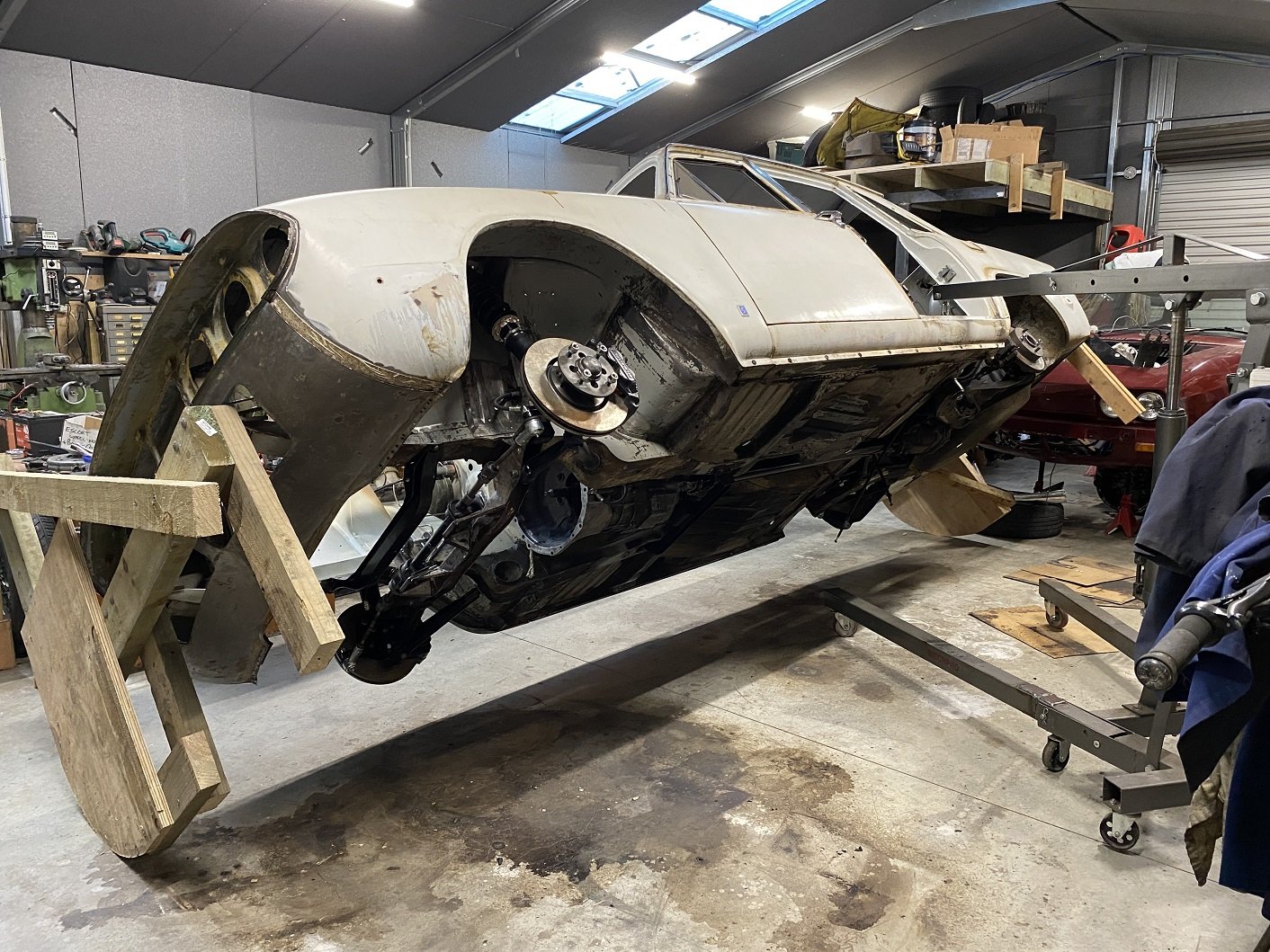
I lifted the rear subframe off. Feels like one of those photos showing off the big fish I caught... With the car like this it made it really easy to measure between the front and rear lower ball joints to find the wheelbase on the drivers side was longer than the passenger side. I suspect it's because I built the alignment jig for the two front mounts on the yellow car, not this one. I had oversized the holes that the studs come through to allow some wiggle room, but I need to take a further 4mm off both sides. Once I can get it on a wheel alignment machine to make sure it's straight the studs will get welded in solid. I've started cleaning off the last of the underseal. I've got to also remove the remains of the original spring seat reinforcement.

- 190 replies
-
- 15
-

-
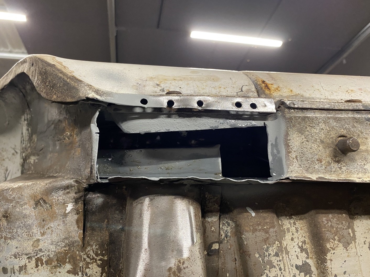
While I've got the underside of the car right in my face, I've been using the hammer to close up any gappy seams and straightening edges. Because I can. The seam at the front end of the sills were a bit squashed from jacking so I knocked and pried them back into shape. While doing that I noticed some pinholes in the flat panel that joins the bottom of the front wing to the seam on the bottom of the sill. I decided to remove that panel. It's basically an 'L' shape so real easy to make a new one.(I've made the new ones using slightly thicker metal) The drivers side sill end was quite pitted under that flat panel because debris gets stuck between them. I cut that out too, it's also flat. It was in AMAZINGLY rust free condition in there. It seemed to be evenly coated with a dark grey primer, this shell must have been dunked in a vat of this primer at the factory for it to be in there. Just for good measure I flooded it with Zinc primer. I did the passenger side too, just to check it was in even better condition. A little pitting, but no pinholes. I tried to take a photo inside but my phone didn't want to use the flash.
- 190 replies
-
- 13
-
-
Yes. I needed to do it for the non-standard method I used to weld mounting flanges to my BC coil overs. I filled out the standard part of the forms then added extra pages at the end with photos of what I had done so far and scale drawings showing measurements and detail of stuff that's not super obvious in the photos. I had my application delivered to LVVTA office. They sent me an invoice for the $150. Then I had to wait until the next monthly TAC meeting. My application was posted back to me within a week of the meeting and it had been approved. If it wasn't approved, I'd expect notes saying what I needed to change or additional detail they wanted. Then I'd have a month to sort it and send in before the next monthly TAC meeting otherwise you have to wait another month.
-
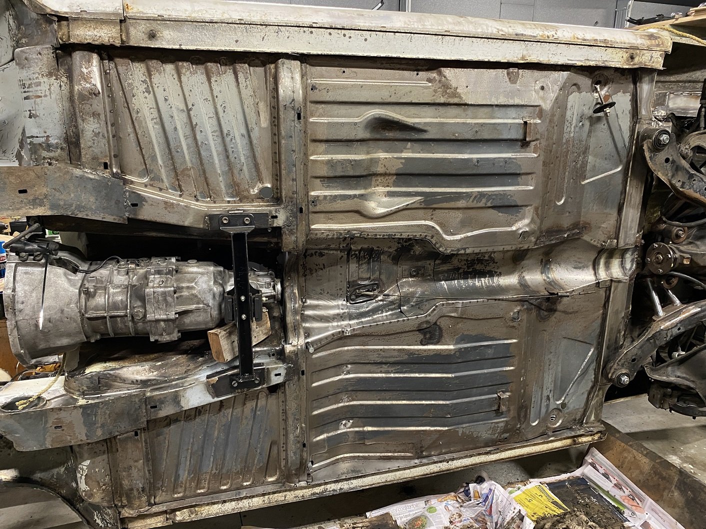
Was each side of the floorpan designed by people in different rooms who refused to talk to each other? The raised sections of floor are not visible inside, there is a second 'floor' that the seat bolts to. Those are pretty much identical. WHY the different shapes?! Is the floorpan also used in the Stag? Is there something there in the Stag?
- 190 replies
-
- 13
-
-

-

-
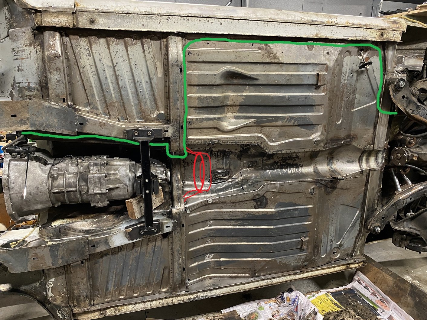
Cool, I'll run them down the side. The driveshaft hoop will be something like the red scribble. The sides of the tunnel and front seat area has two 'floors' with a cavity for some reason so I was planning on bringing the hoop mounts forward to the chassis box section.
-
Do I recall something about proximity of things like fuel line, battery cable and brake line to the propshaft when routing under the car? Or does it not matter where I run them as long as it's secure, not going to hit the ground and can't touch things that move or spin?
-
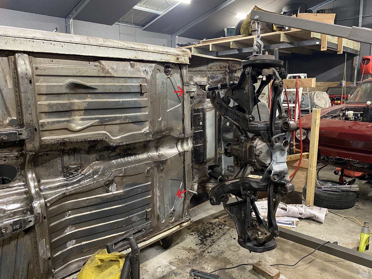
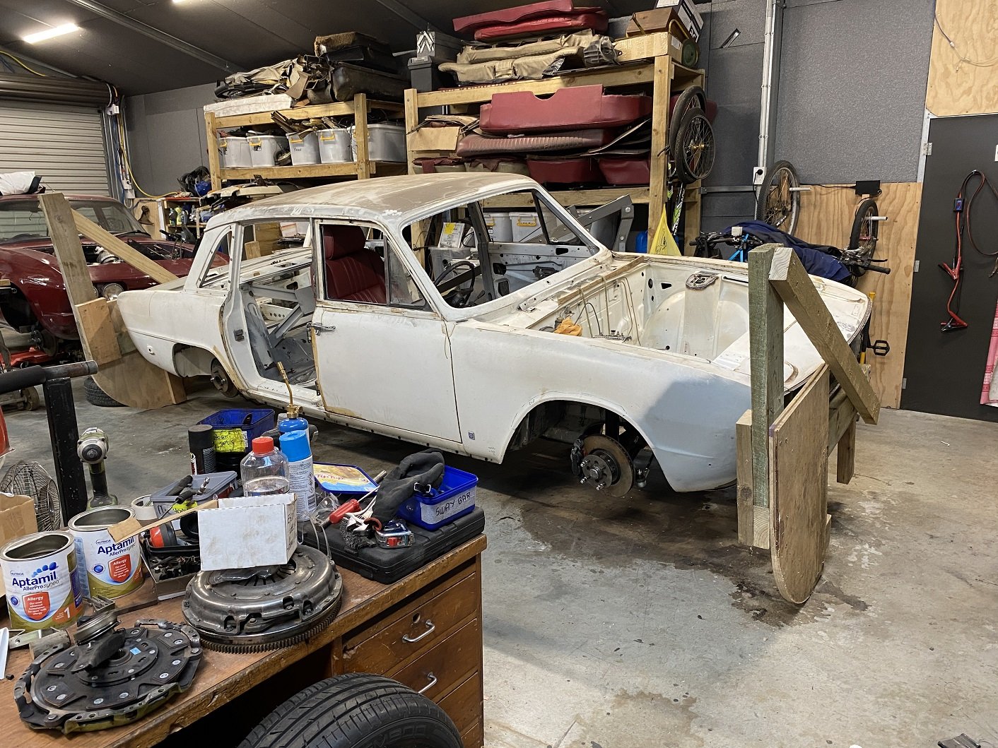
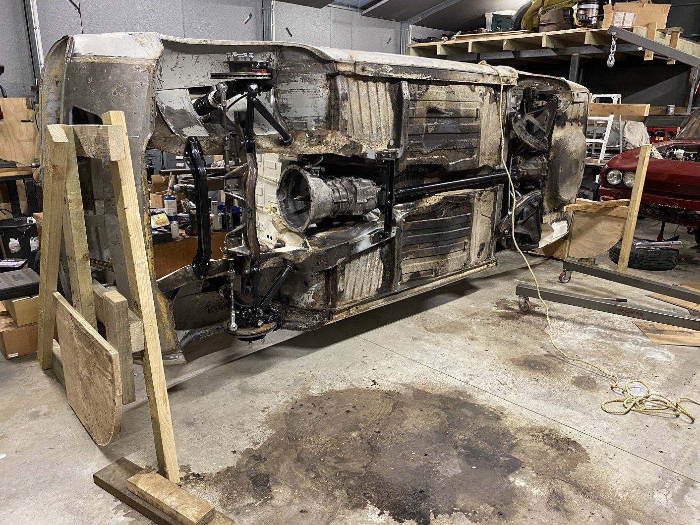
This make some things easier.... I bolted the don't-fall-on-me props on so they can't accidentally be knocked out. It's a bit bottom heavy with all the suspension still attached so it does want to come back down.
- 190 replies
-
- 21
-

-
-
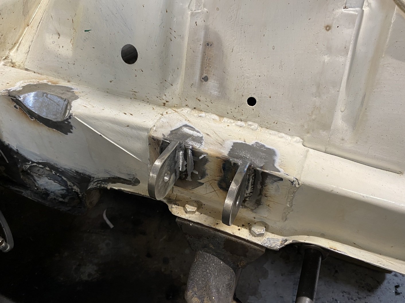
Engine mounts redone in thicker material as advised by the man. 8mm should do it. I machined up a spacer and did half at a time so I could use the original half to keep the alignment. But I also added a 4mm spacer when welding on the first new half to shift the engine back a tiny bit and give me just a little more clearance between the cross member and the sump. I hope that doesn't come back to bit me in the arse later. When welding in the second half of each mount I replaced the 4mm spacer with a fibre washer as a shim so it's not such an uber tight fit to get the bush/sleeve in there.
- 190 replies
-
- 21
-
-
The stuff I have on my shelf is Duplicolor. I'll try some VHT. Thanks.
-
Discovered that the caliper paint I've used is rubbish. Blasted half off half of it with compressed air. They are aluminium so won't rust. Does anyone recommend something that actually sticks and comes in a spray can?
-
Is the bar trying to occupy the same space as the intercooler? Tetris harder.... Or was it just blocking airflow? I'd just let it block that top section of the intercooler, it will probably still do some cooling in that section.
-
I'm running them high because the there is very little space between the engine and firewall. I came across a Staaaaaaaag brake diagram on Rimmer Bros which looks identical to the 2500 tandem system. The same master cylinder is listed for both cars. Front port goes to the rear brakes. I'm going to have separate short sections of pipe going to the master cylinder, so if It's wrong, I only need to remake those short bits.
-
Could anyone else with a Triumph that has a tandem brake master cylinder check which ports are for the front/rear please. AFAIK, both lines go to a 5 port pressure imbalance switch thing on the passenger side. Then one comes back for the FR brake, one goes to the FL and another goes to the rear. I've looked in the two workshop manuals and factory blue manual I have but they only show the routing for the earlier single circuit system.
-
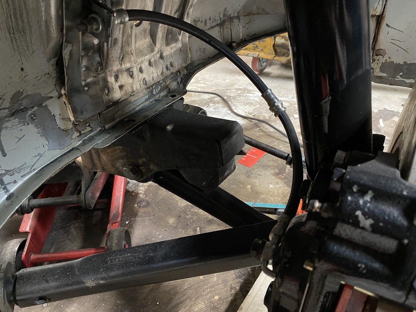
A clutch line. Bent by hand so not robot straight. I made it a little longer than required just in case I need to redo the flares. Hopefully having it go higher than the reservoir do not cause issues bleeding. The reservoir is just on a hose and bracket, so I could make it higher if I needed to. And the hose bracket I made. With the hose like this it keeps out of the way of the wheel and it doesn't get tight from lock to lock. The hardline originally went under the chassis rail, but it will be way too close to the exhaust, I'll run it through the inner wing.
- 190 replies
-
- 16
-